Micro:bit in the Classroom: Teach Robotics and Automation With 3 Simple Projects
by M.C. Langer in Teachers > Robotics
16388 Views, 121 Favorites, 0 Comments
Micro:bit in the Classroom: Teach Robotics and Automation With 3 Simple Projects
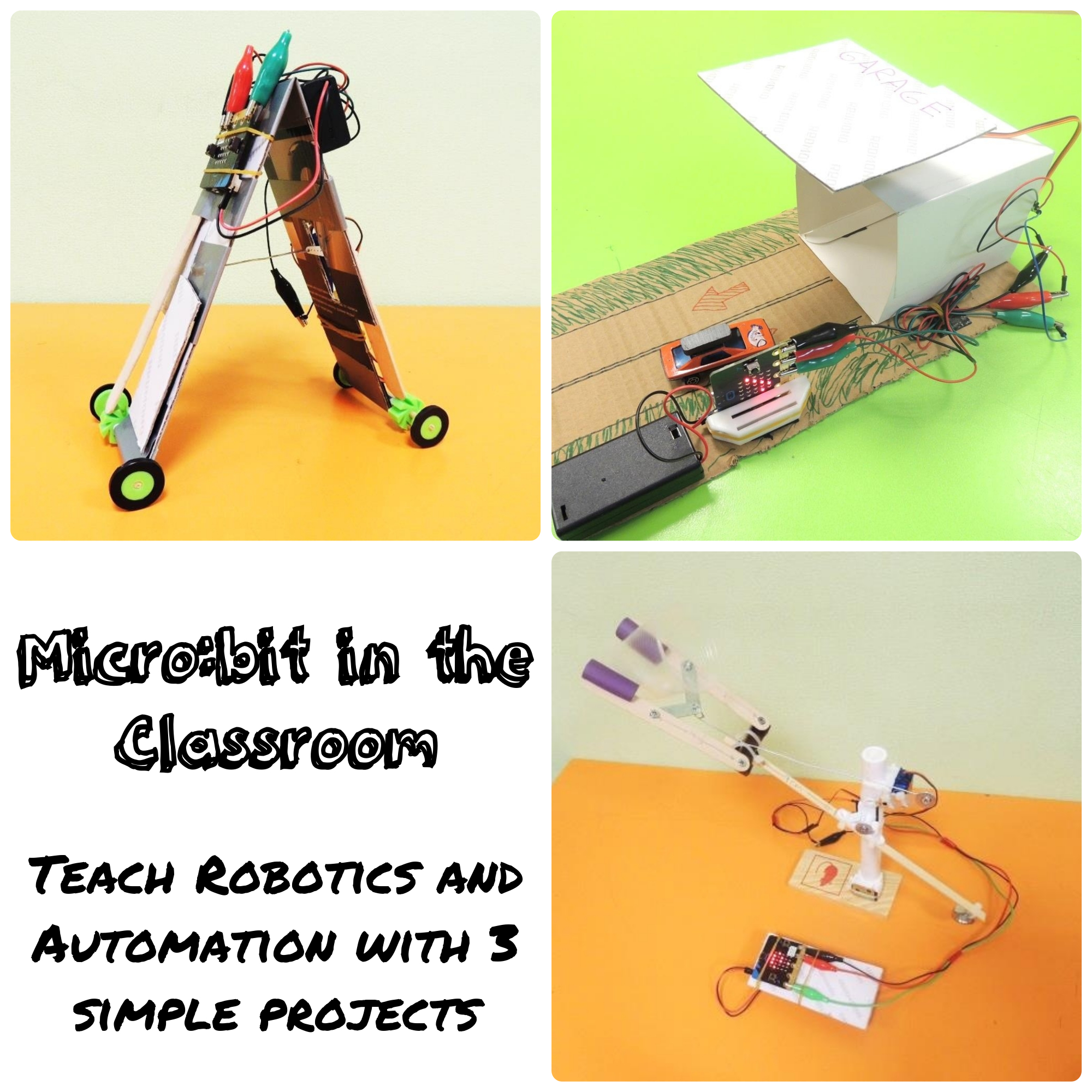
(Hi! I'm participating in the Robotics Contest. If you like my instructable, your vote will be very appreciated. Thanks, and have a great day!)
BBC Micro:bit is a great electronic board to teach kids about coding, electronics and other STEAM subjects. Nevertheless, if your idea is to create Micro:bit robots as a classroom project, you will need to buy several kits with extra components. Do you want to build a robot arm? This kit for $53.99 will do the trick. Do you want to create a gracious robotic insect? Prepare $26.99 from your pocket (and the Micro:bit and power source are not even included). I just mentioned the cheapest options, limited to only one idea to build. And you will need to buy several of them, at least one per every two students in your class.
But if your school is in a budget, and you have only a basic Micro:bit Educator Pack, or the classic Micro:bit Go bundle, plus some servos and wires, probably your robotic options are very limited.
Well, fear not! In this instructable I will teach you how to create three robotics and automation projects using only these basic Micro:bit components plus some easy-to-get materials. The main benefits of these lessons are:
- Affordable: except for the Micro:bit and the servos, all the materials are easy and cheap to get from local markets, hardware stores, 1-dollar stores. Even you can get them for free, if you have a good recycling program in your school.
- Eco-friendly: not only because of the recycling campaigns I just talked about. All the components are attached in a temporal way. Except for the zip ties and the adhesive tapes, everything else is reusable for the next lesson!
- Easy to build and program: you don't need special tools to build these robots. Even hot glue guns were avoided. Maybe teachers will need to drill some holes before the lesson, but nothing that cannot be solved with some pointy scissors. And if well one of the lessons requires a 3D printer, these pieces can also be created using cardboard.
- Multidisciplinary: In "Inchworm", students will be required to use Tinkercad and a 3D printer to create some mechanical pieces. In "Robot Arm", kids will explore physics concepts like simple machines, levers, fulcrum and counterweight.
- Compatible with simple and advance kits: if well these lessons were created with the basic Micro:bit kit in mind, it also can be used with more advance sets.
GRADE: 5-7
SUBJECTS: Science (Physics), Robotics, Art, Handwork, Computer Science, Computer-Aided Design (CAD), 3D Printing, Environmental Sciences (Reuse, Recycle)
First Project: Smart Garage
Introduction:
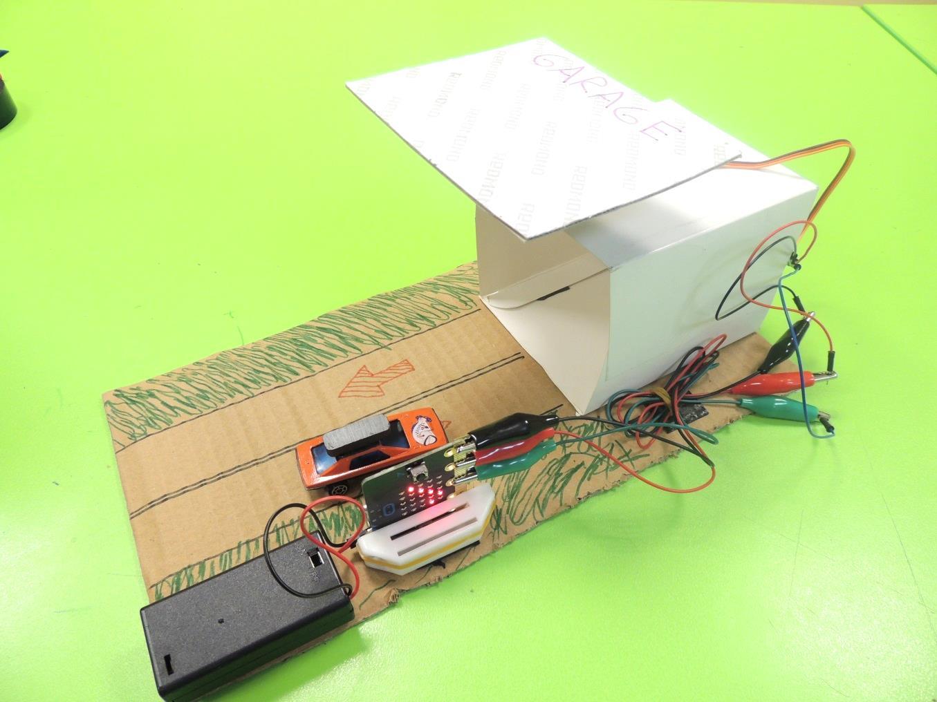
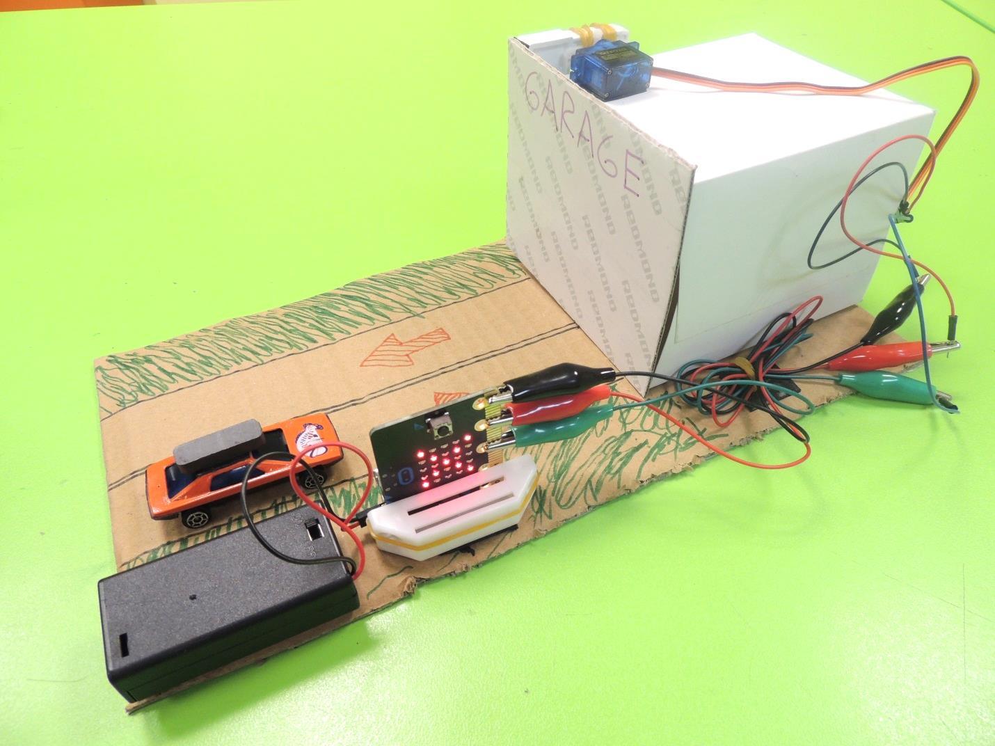
The BBC Micro:bit has several integrated sensors that can read information from the surroundings. One of them is the Compass. This sensor uses a magnetometer chip to detect and measure magnetic fields. In this lesson, students will apply basics of electrical engineering to create a smart garage activated by magnetism. This garage is usually closed, but when a car with a magnet comes in front of the Micro:bit, a servo will open the door, granting access to the car. After a few seconds, the door of the garage will close automatically.
Definitions:
- Automation: technology by which a process or procedure is performed with minimal human assistance.
- Magnet: material or object that produces a magnetic field.
- Magnetometer: sensor that measures the direction, strength, or relative change of a magnetic field.
- Servo (servo motor): component that integrates a motor, a gear box and a sensor to control the position of the shaft.
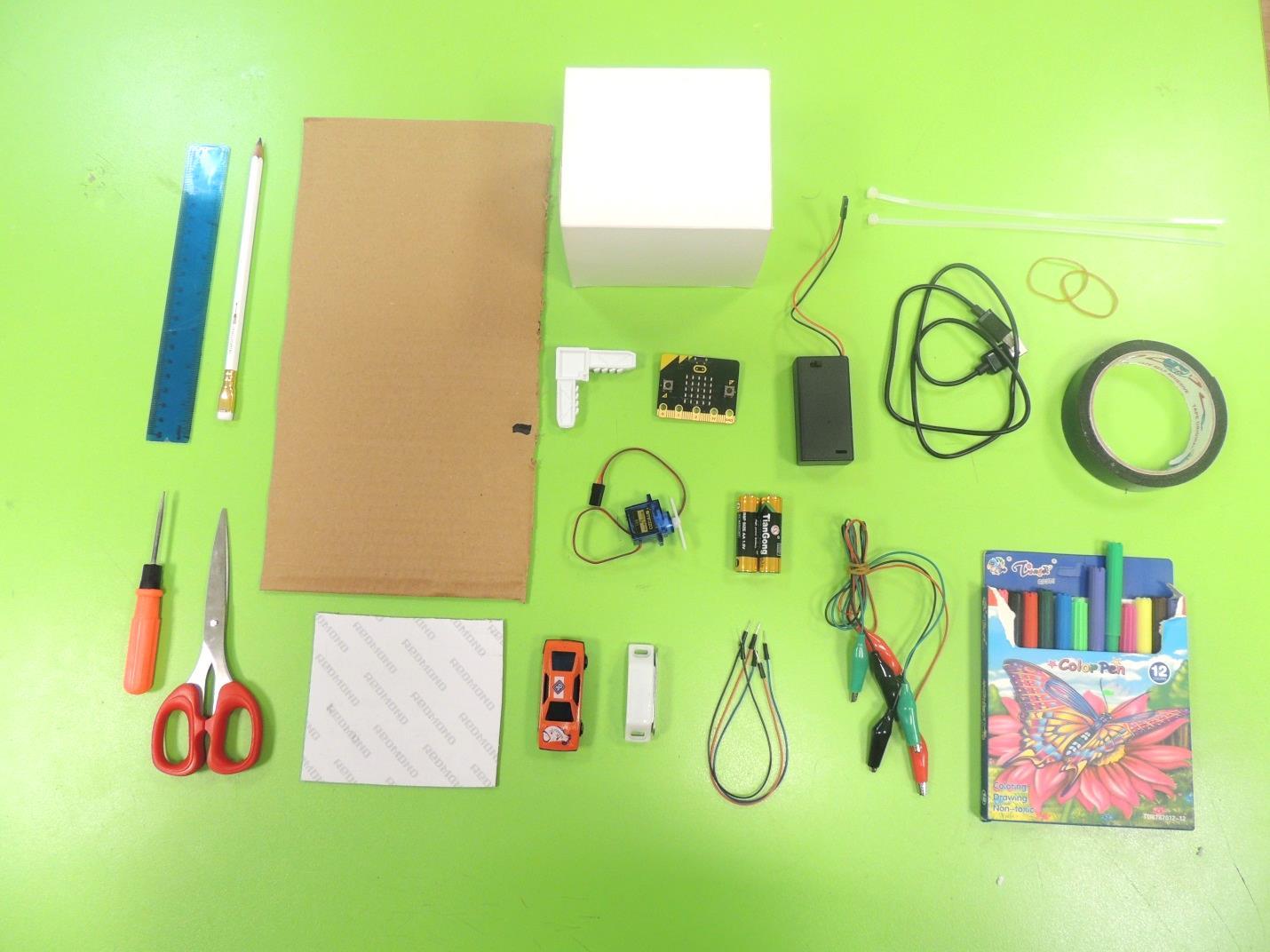
Materials per student/team (2 kids)
- 1 BBC Micro:bit board
- 1 2 AAA Batteries holder with plug for Micro:bit
- 2 AAA Batteries
- 1 USB cable for Micro:bit
- 1 Servomotor with double-arm horn and screw
- 3 Alligator Test Leads (red, black and blue)
- 3 Jumper wires (red, black and blue)
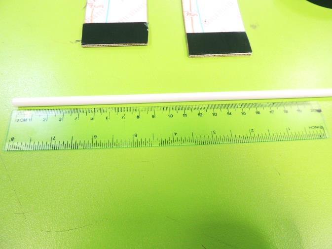
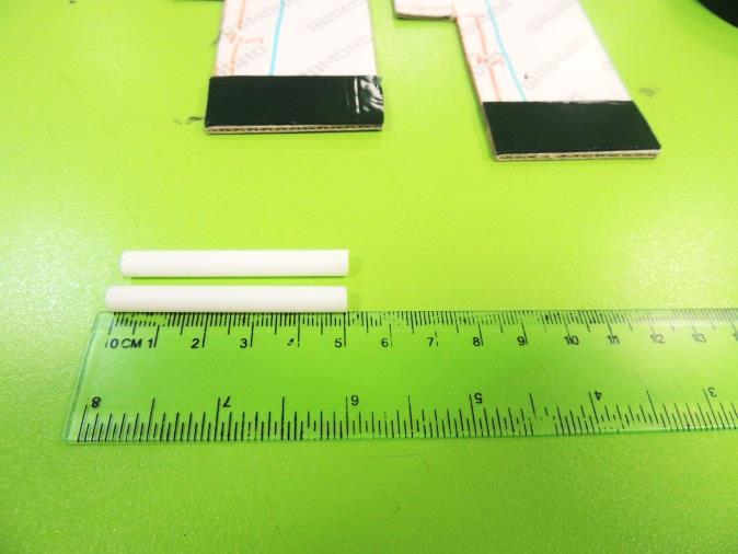
- 1 Mounting Tape (double-sided)
- 1 magnet for cabinet
- 1 pair of scissors
- 1 flat screwdriver
- 1 cardboard box (10cm x 10cm x 10cm approx.)
- 1 cardboard sheet (11cm x 11cm approx.)
- 1 cardboard sheet (15cm x 40cm approx.)
- 1 small plastic angle for mosquito net frame
- 3 zip ties
- 2 rubber bands
- 1 small toy car (Hot Wheels style)
- 1 ruler
- 1 pencil
- 1 set of color markers
- 1 Computer with internet access or Makecode offline editor installed.
- OPTIONAL: 1 extra magnet for opening the door when the car is inside the garage.
Pre-Lesson
- Make bags with the materials to distribute later to each kid.
- Verify that your classroom has access to internet. If not, download and install the offline Makecode app on each computer (https://makecode.microbit.org/offline-app)
- Make a prototype of this project, so you can show it to the students.
Micro:bit Code
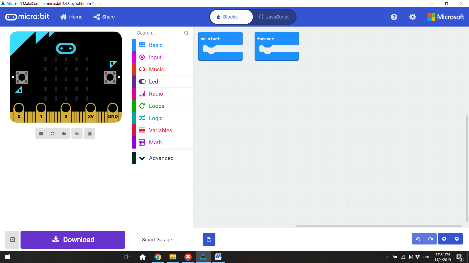
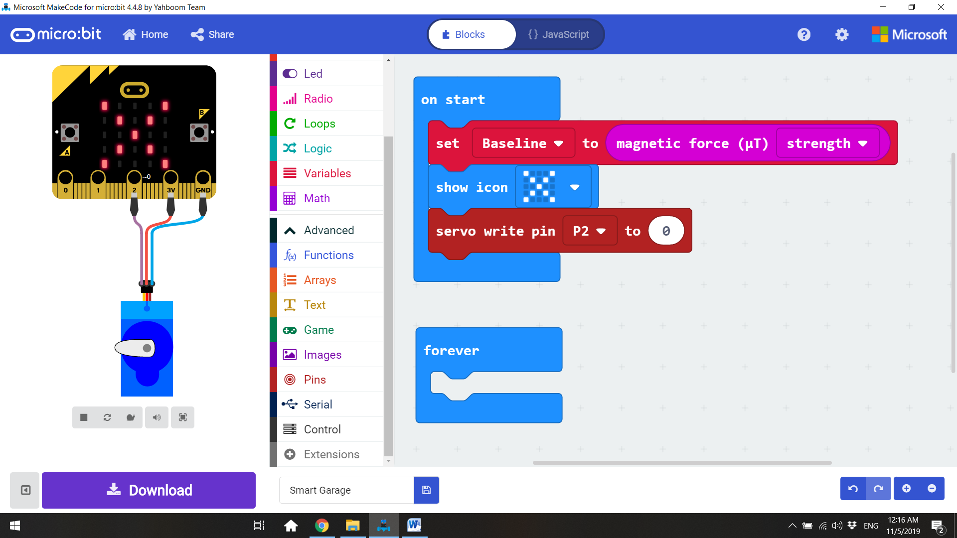
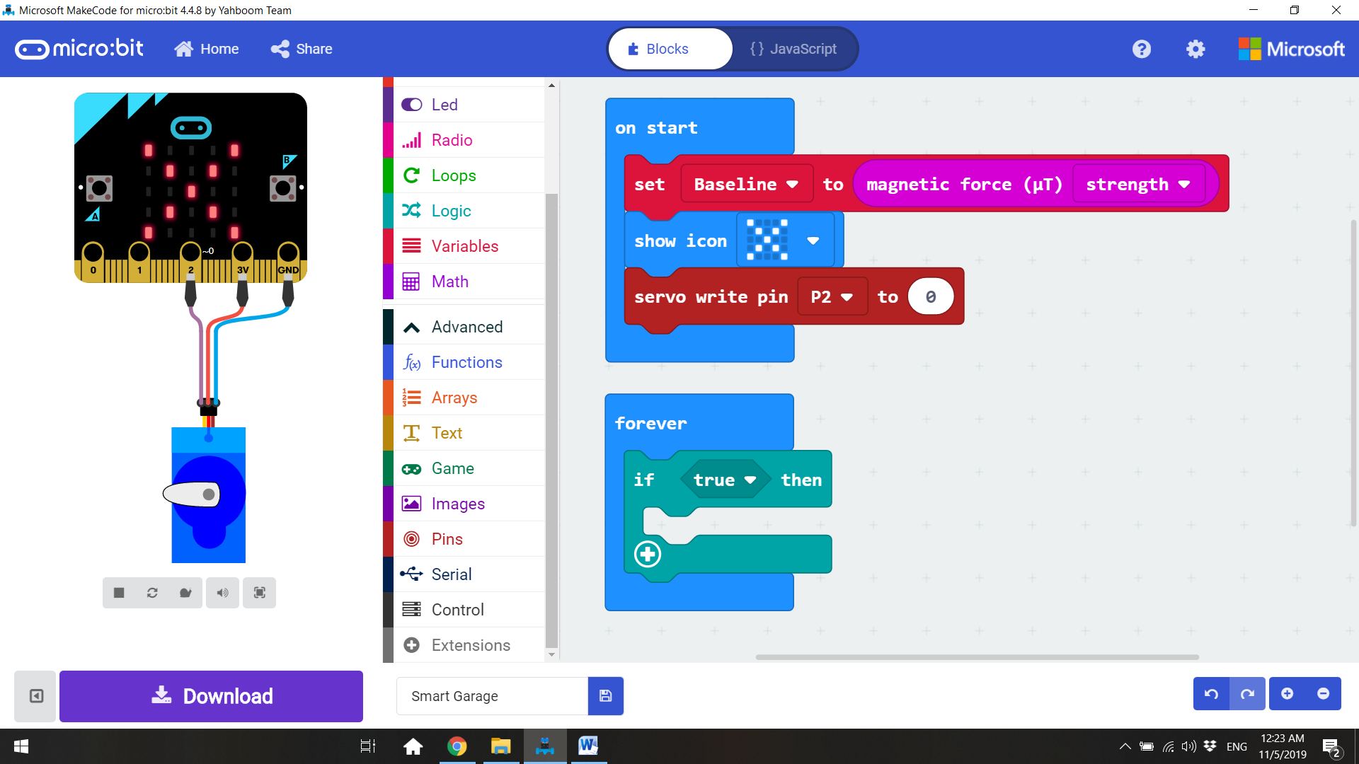
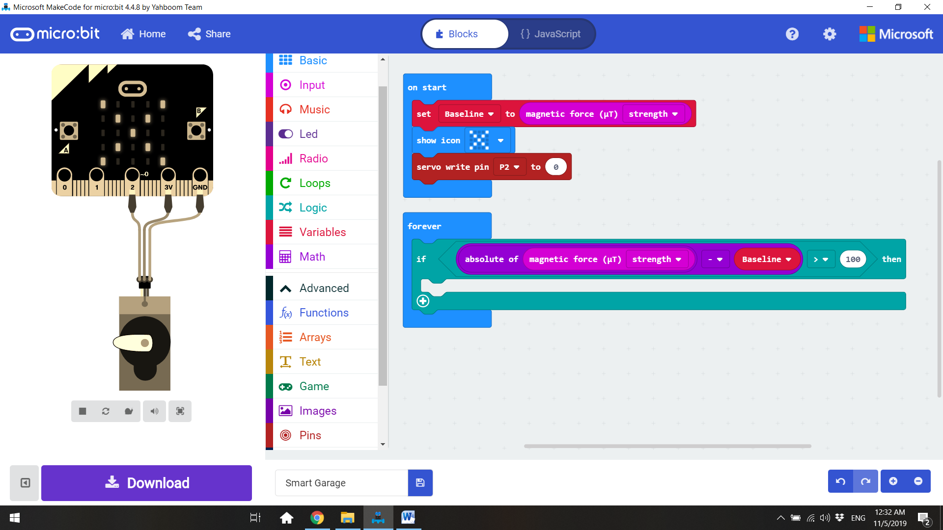
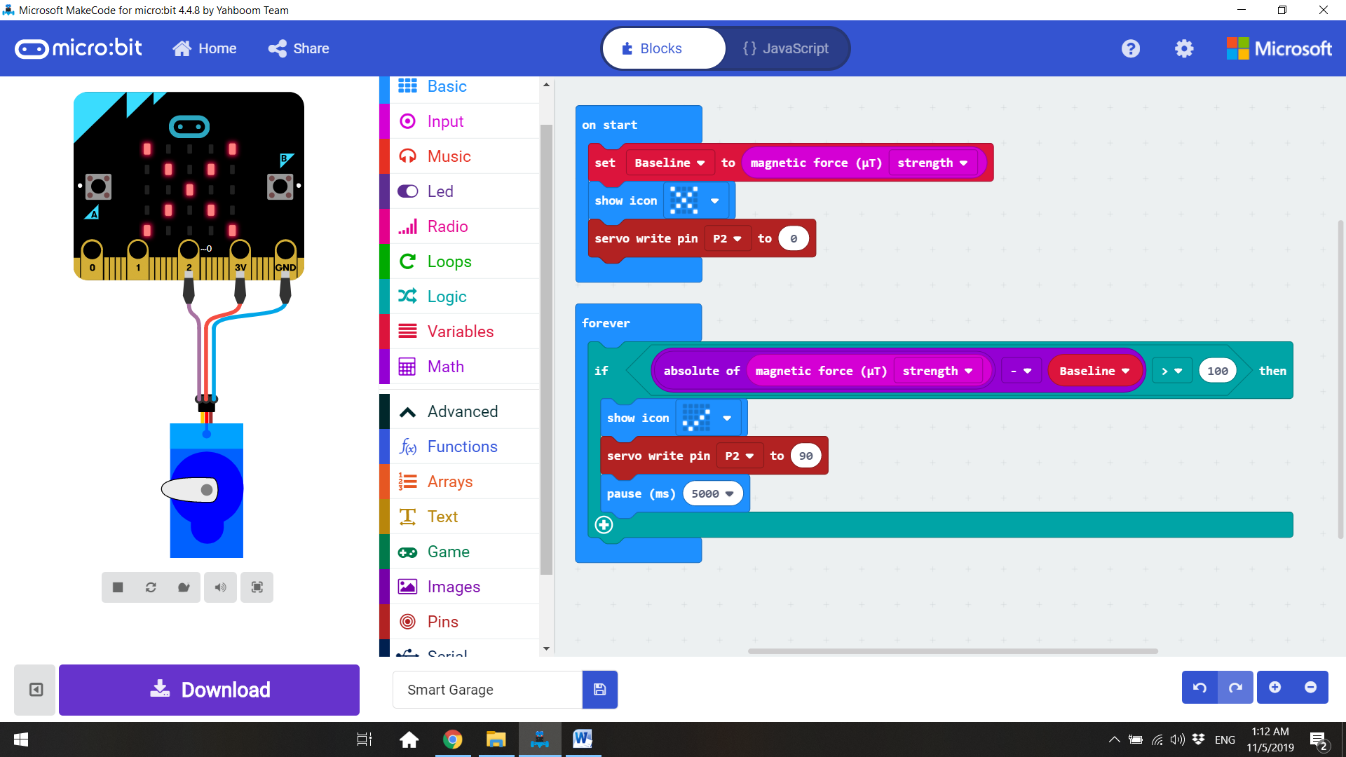
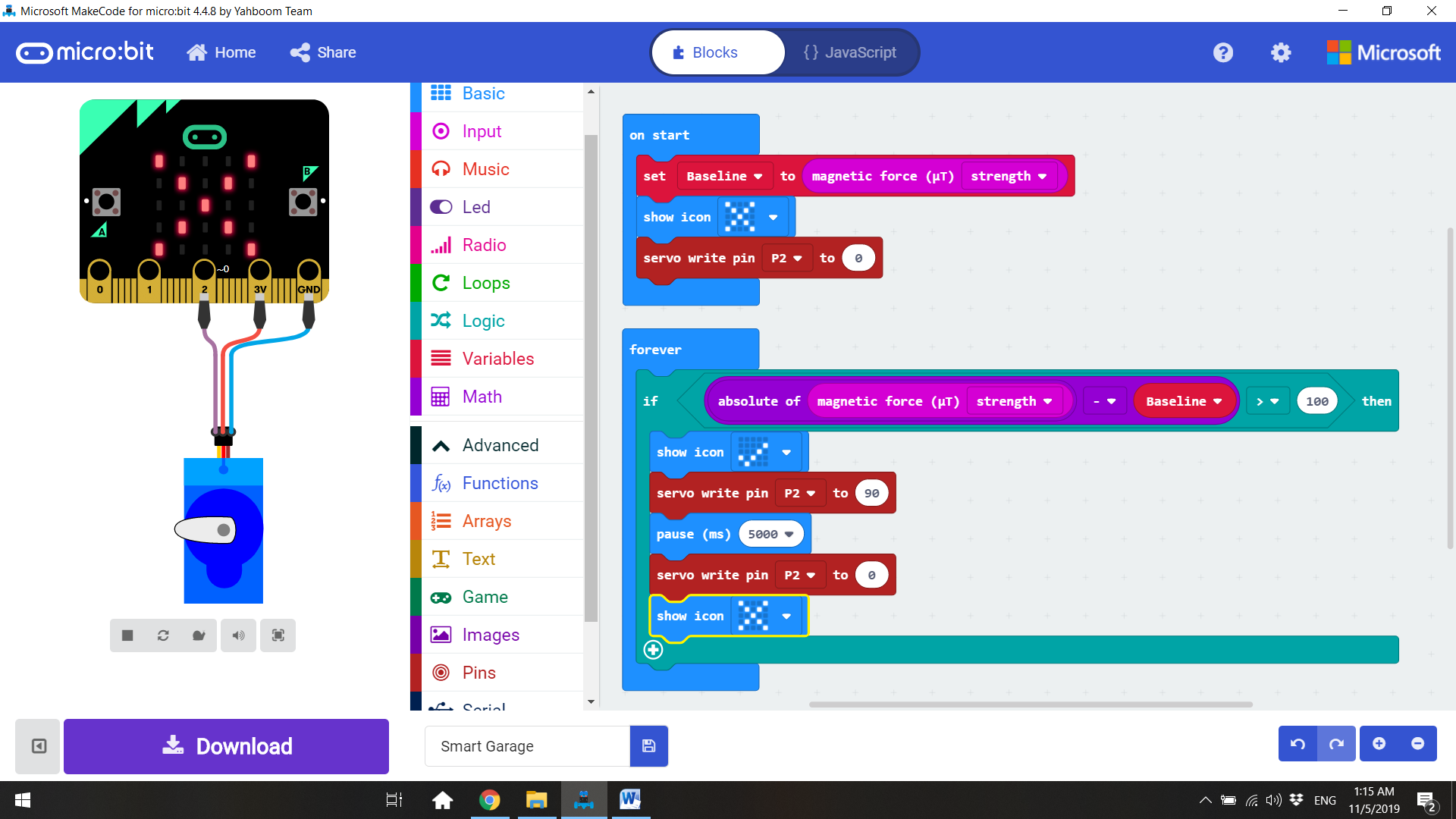
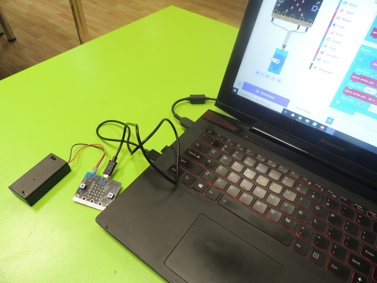
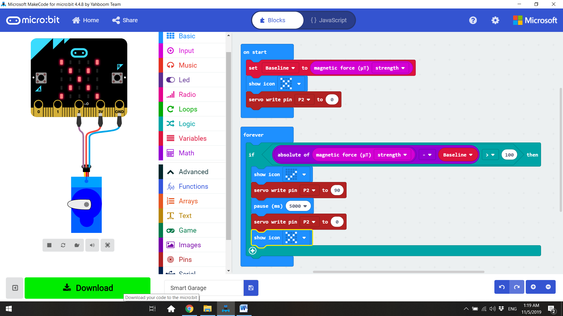
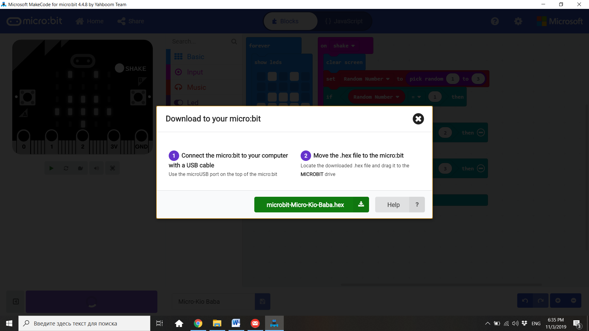
1. This lesson will be divided into two sections: a coding one and a hardware one. First, kids will create and download the code, so they get familiarized with the different program blocks. Then they will create the physical part of the garage, including an electromechanical door and the wiring for the Micro:bit board.
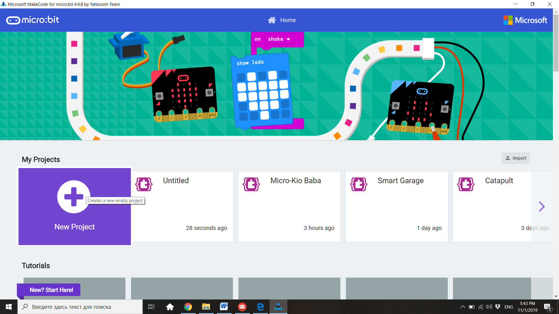
2. Students must open Makecode and click in “New Project”.
3. Click the word "untitled" and rename your project "Smart Garage".
4. Remind to the students that the Micro:bit has three digital pins in its basic form: 0, 1 and 2. Also, there are a 3V pin and a GND (ground) pin to power some special electronic components. The servomotor will be connected to the pins 3V and GND to power it, and to pin 2 to control it.
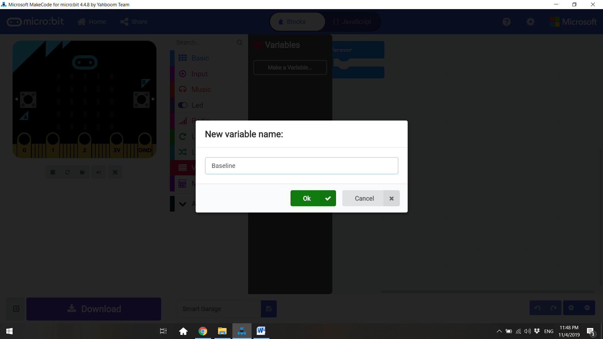
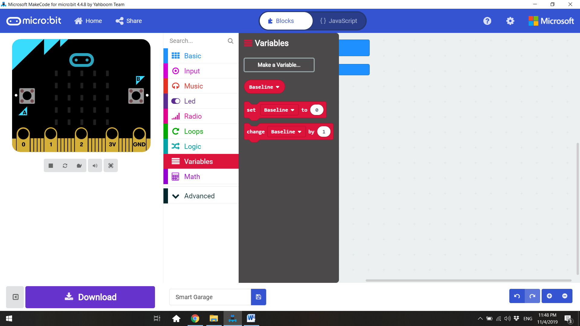
5. First, we need to go to “Variables” and create a new variable for the magnetic strength with no magnet near the Micro:bit. We will call the variable “Baseline”
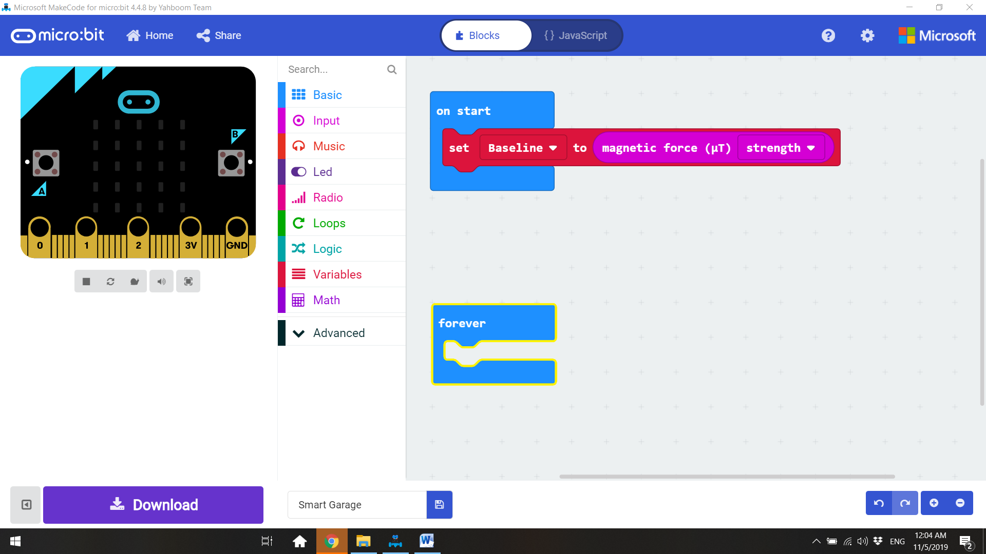
6. From the “Variables” group, bring the “set Baseline to” block and insert the “magnetic force” block changed to “strength”, from the “Input – more” group. The magnetic force is measured in microteslas. When the Micro:bit is first powered up or the reset button is pressed, this reading will be considered the default magnetic force in normal situation (no magnets near).
7. Now we will bring the “show icon X (No)” block from “Basics” and “servo write pin P2 to 0” block from “Pins”. This way, the program will start running with the door of the garage closed and a no access allowed signal.
8. Inside the “Forever” loop we will insert a “if true then” block from “Logic”.
9. Now we will create the condition that will allow the door to be opened. The “Forever” loop repeatedly takes readings and checks to see if the absolute value of the difference between the new reading and the Baseline reading is above 100; and if it is, it will activate the next part of the script. The absolute value is just the value with the sign removed. This is necessary because, depending on which pole of the magnet is pointing towards the compass chip, the magnetic force reading may decrease rather than increase. First, insert the “0>0” comparison block from “Logic”. In the first slot, bring the blocks “0-0” and “absolute of” from “Math”. Then, fill the slots with “magnetic force strength” and “baseline”.
10. If the absolute of the magnetic force strength minus the baseline is greater than 100, the display will “show icon – Yes” and send a signal to “servo write pin P2” to move the door 90 degrees and keep it open for 5 seconds; time enough to drive the car inside the garage.
11. After 5 seconds, the servo connected to pin P2 will close the door (return to 0 degrees) and show the icon X (No)
12. Press the “Download” button to download your code as a .hex file. When you download the code, it gets compiled from Javascript into ones and zeros that the Micro:bit can store and execute. You can find the code in the “download” folder of your computer. Drag the downloaded code over to your Micro:bit, just like dragging and dropping a file to an external drive or USB stick. You should see a yellow LED flashing next to your USB. This means the code is being transferred. When the LED finishes flashing, the program is fully downloaded.
Compass Calibration
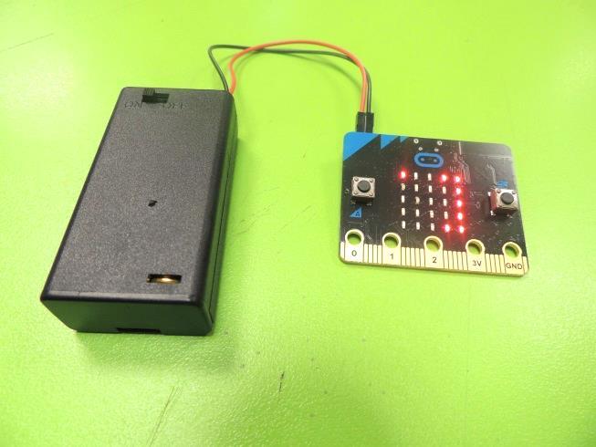
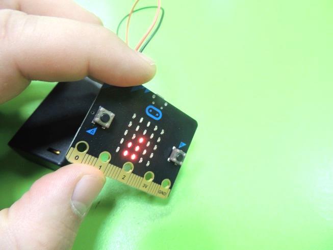
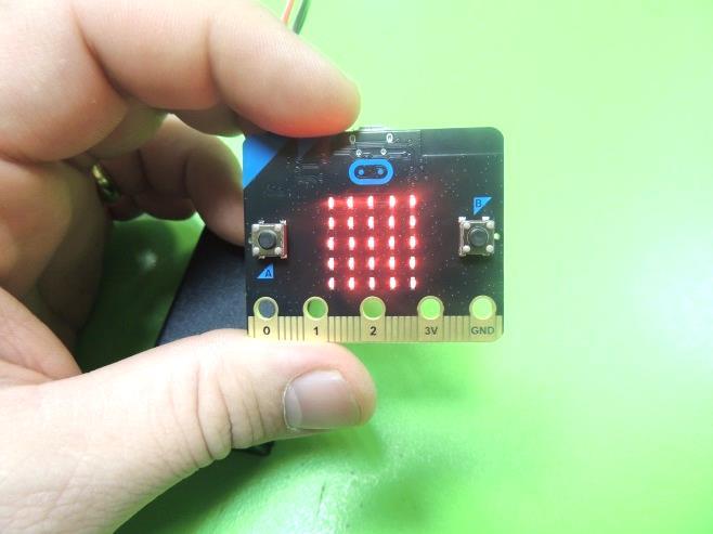
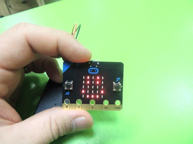
13. NOTE: Usually the Compass needs to be calibrated when the program starts. The Micro:bit will automatically take you through a calibration process that involves tilting the Micro:bit around in a circular motion in order to light up all the LEDs on the display. When you finish this task, a “happy face” will indicate that the program is ready to run.
Preparing the Car and the Parking Spot
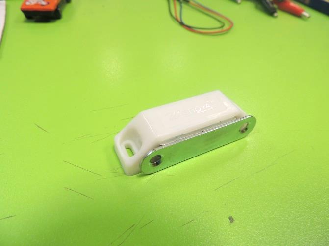
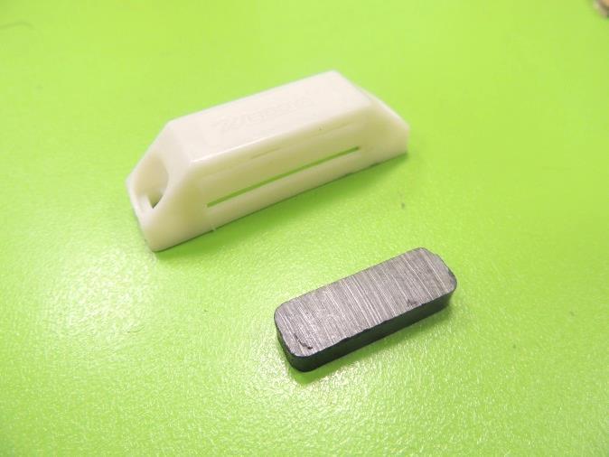
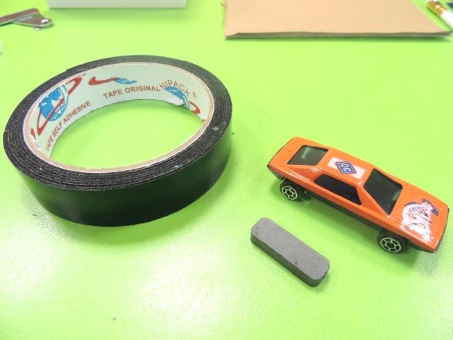
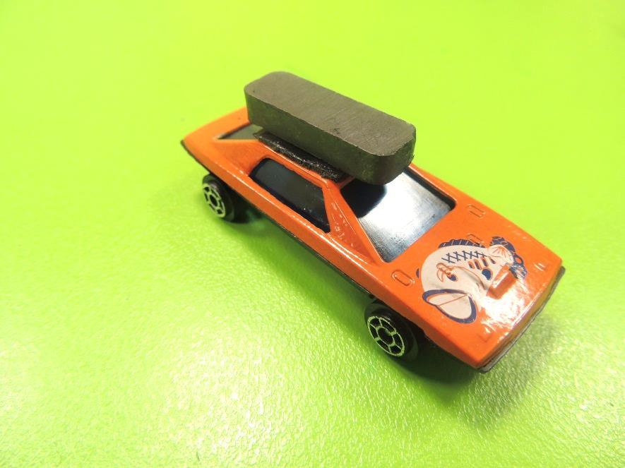
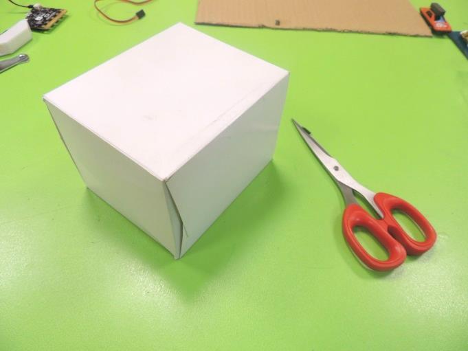
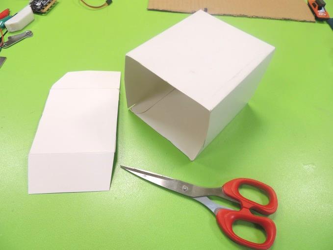
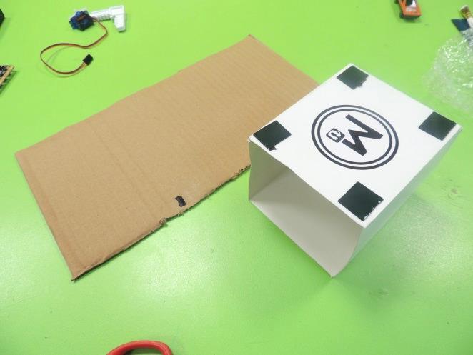
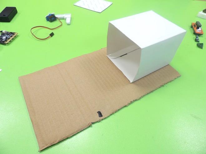
14. Take the cabinet magnet and disassemble it using a flat screwdriver. You will need the magnet and the plastic case.
15. Using a piece of mounting tape, stick the magnet to the roof of the toy car.
16. Using the scissors, cut one of the sides of the cardboard box.
17. Stick the box to the cardboard sheet, using mounting tape. The cardboard sheet will be the access to the open side of the box.
Garage's Door
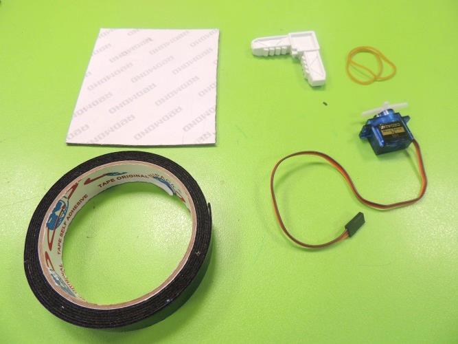
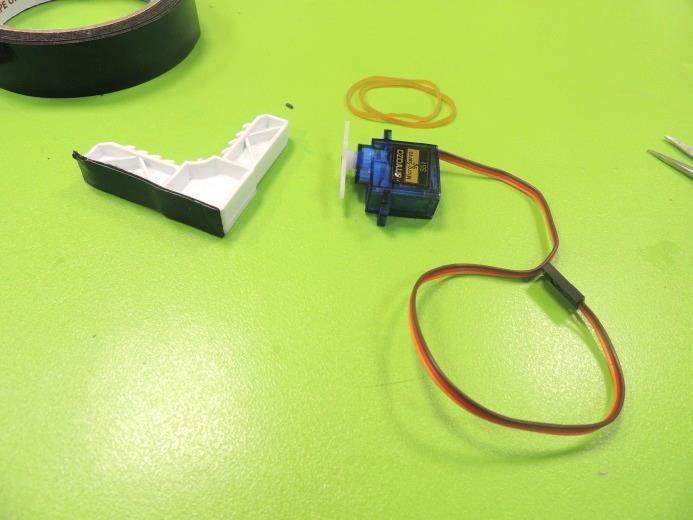
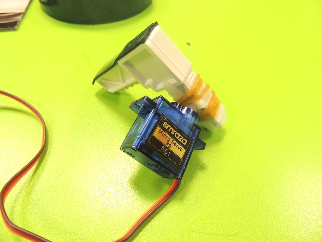
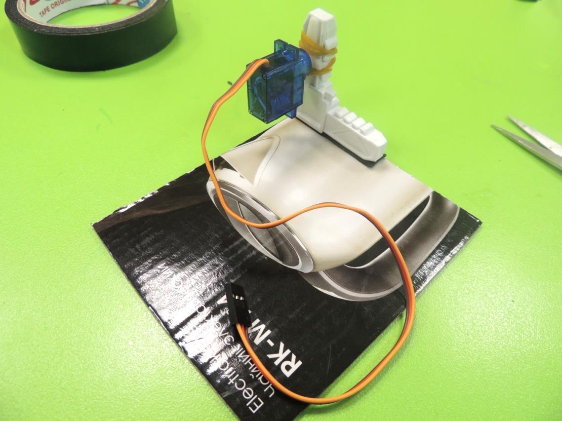
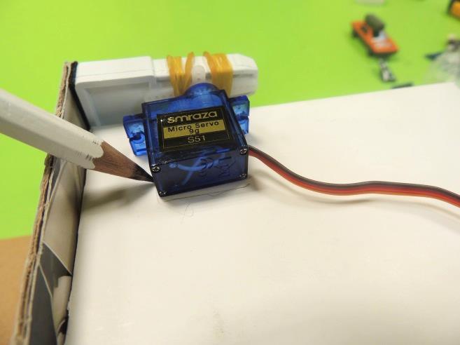
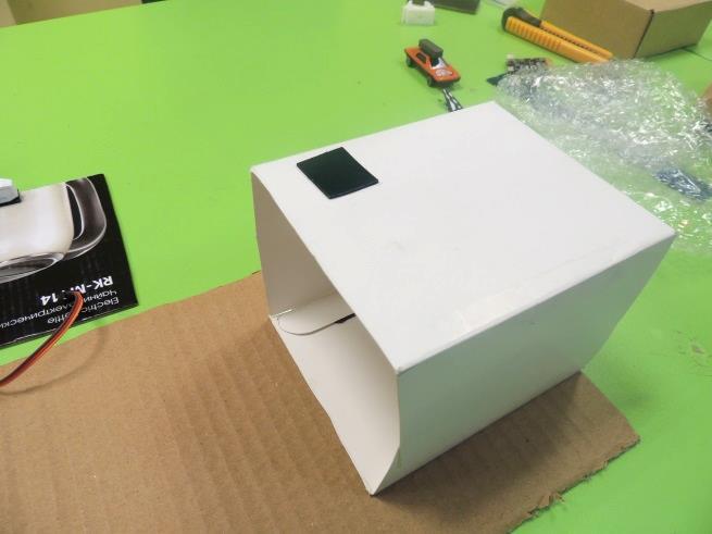
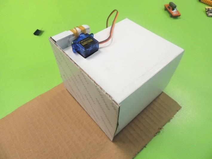
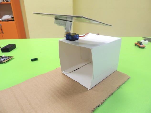
18. Now we will build the door. Attach the plastic angle to the servo arms, using rubber bands (if it is hard for the kids, they can try with zip ties, being careful of not breaking the servo arms). After that, stick a piece of mounting tape to the available arm of the plastic angle.
19. Remove the peel from the mounting tape and stick the plastic angle to the top right corner of the smaller cardboard sheet. 20. Place the door closing the open side of the box, and mark with a pencil the exact place where the servomotor may be placed. Stick a piece of mounting tape in that area and place the servo there. Be careful of not using the side of the label with the servo’s info. Test that the door can be opened and closed without any issue.
Parking Booth
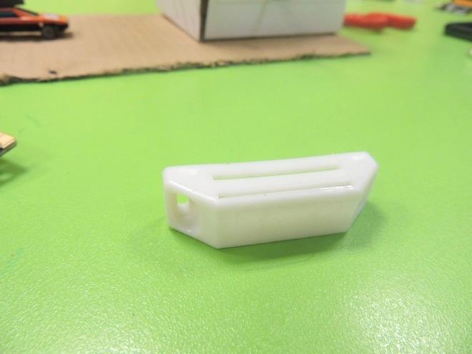
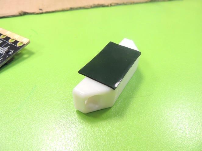
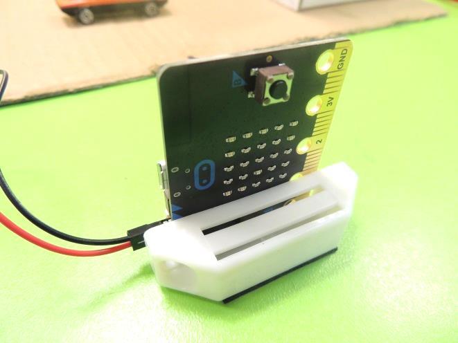
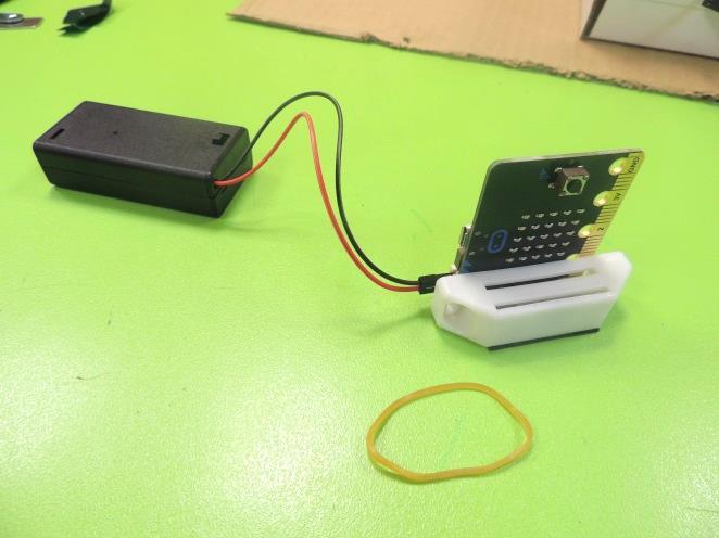
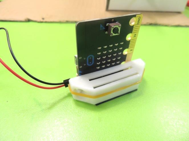
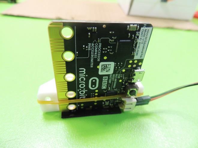
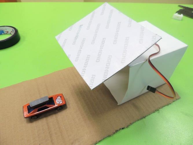
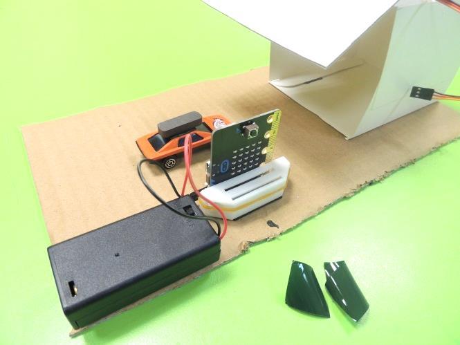
21. Take the plastic case from the cabinet magnet and stick a piece of mounting tape in one of the sides. This spot will be placed later over the cardboard sheet. Then bring the Micro:bit and stick it to the bottom of the case (hollow part) using a rubber band. Verify that the rubber band, the mounting tape and the plastic case are not affecting any critical part of the Micro:bit (covering a sensor, adding extra stress to a socket or button.)
22. Choose a point where you can place the Micro:bit (as a “parking booth”). The place must be in a point that doesn’t affect the door’s movement when is opening or closing. Also, it must be close to our car so the magnetometer can detect the magnet. Remove the peel from the plastic case’s mounting tape and stick the booth.
Wiring the Micro:bit With the Servo and Customization
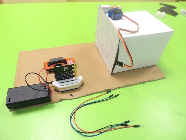
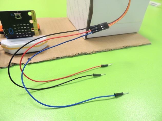
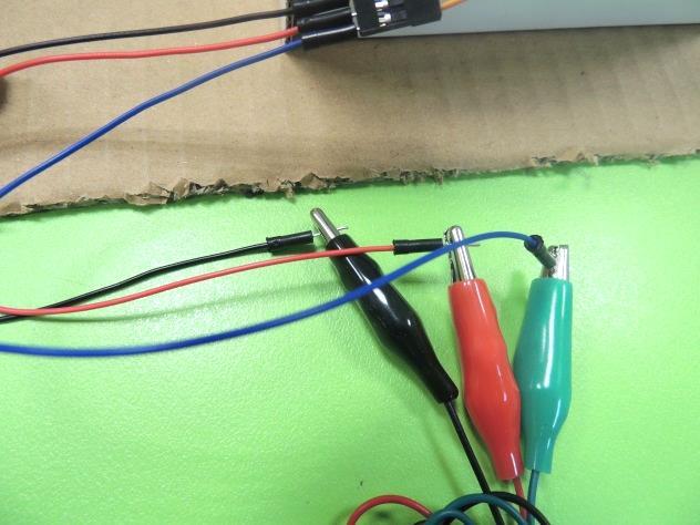
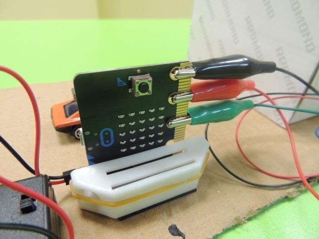
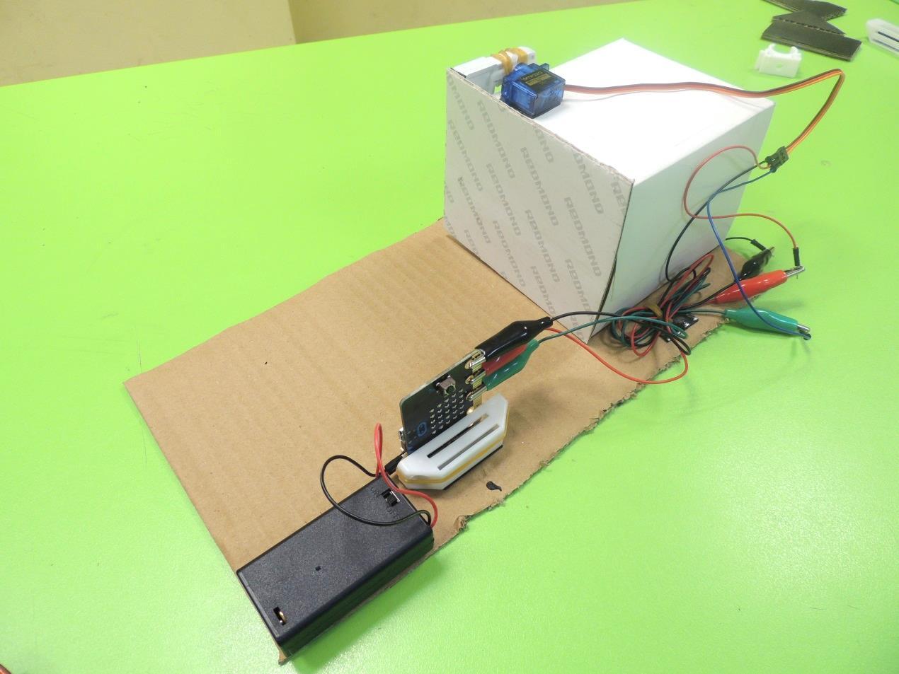
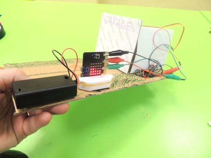
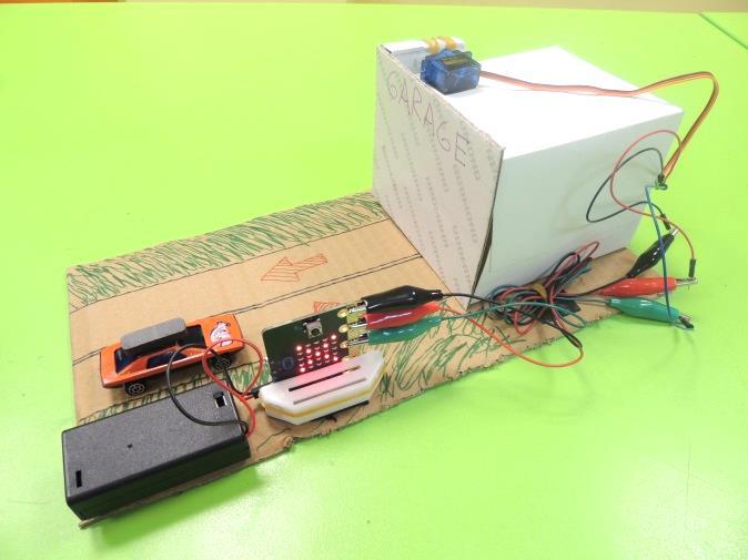
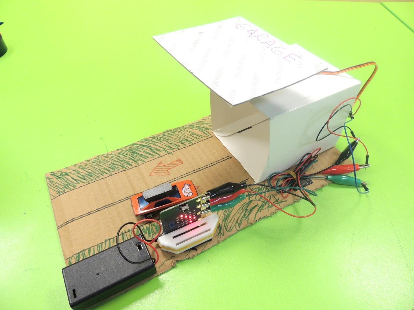
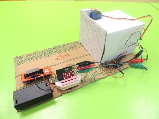
23. Now we will do the electrical connections. Take the jumper wires and insert a red one in the socket of the servo’s red cable; the black one in the socket of the servo’s brown cable; and the blue one in the socket of the servo’s orange cable. Using the alligator cables, connect the black jumper wire to the GND pin of the Micro:bit; the red jumper wire to the 3V pin, and the blue jumper wire to the digital pin 2. To organize the cables in a better way, you can tie them with a rubber band.
24. Customize your garage using markers. Test it. In case the Compass of your Micro:bit needs to be calibrated again, it is not necessary to remove it from the project. Carefully move the garage until all the leds are on.
25. At the end of the lesson, students must return to the teacher the Micro:bit, the servo motor, the cables, the battery holder, the batteries and any other element that can be reused.
Second Project: Inchworm
(Note: this lesson requires two days to be completed)
Introduction
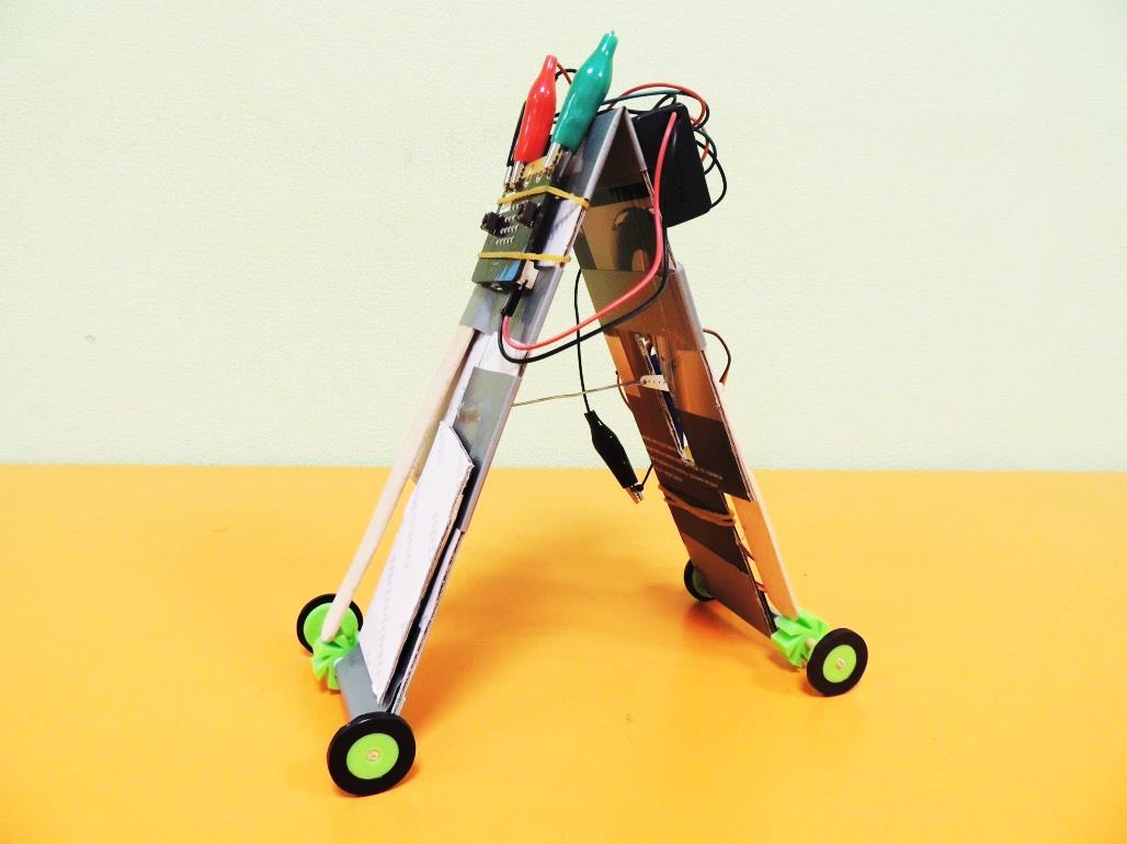
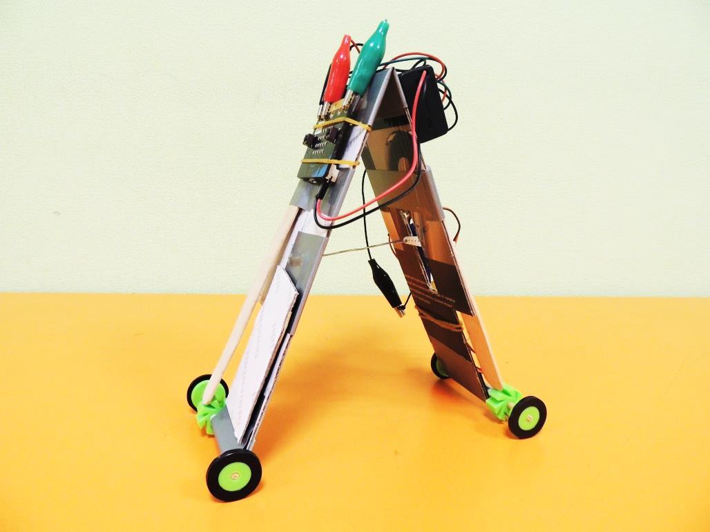
Today we will start a two days project, where students will apply CAD, 3D Printing, Engineering and Micro:bit to create a biologically inspired robot: the Inchworm. Based on the eponymous insect with one of the most peculiar ways of mobilization in animal kingdom, this robot moves extending his front part and then, retracting its back part to advance.
This lesson is divided in four parts that will be covered in two sessions. First, students will use Tinkercad to design and 3D print some special mechanical components, critical for the movement of our robot. Second, students will create the Micro:bit code for the robot. Then, when the 3D printed parts are ready, kids will build the robot. In the final part, students will test and improve their robot, until it can reach the maximum efficiency in movement, and then they will have an Inchworm Race to check which robot arrives first to the finish line.
Definitions:
- 3D Printing: or Additive Manufacturing is a process used to create a physical (or 3D) object by layering materials one by one based on a digital model.
- Bionics: application of biological methods and systems found in nature, to the study and design of engineering systems and modern technology.
- CAD (Computer-Aided Design): use of computers to aid in the creation, modification, analysis, or optimization of a design. Caliper: device used to measure the distance between two opposite sides of an object.
- Diameter: straight line that passes from border to border of a circle, and through the center of it.
- Inchworm: caterpillar from the Geometridae family of insects, famous for its particular way of locomotion: clasping with its front legs and drawing up the hind end, then clasping with the hind end and reaching out for a new front attachment; creating the impression that it measures its journey.
- Servo (servo motor): component that integrates a motor, a gear box and a sensor to control the position of the shaft.
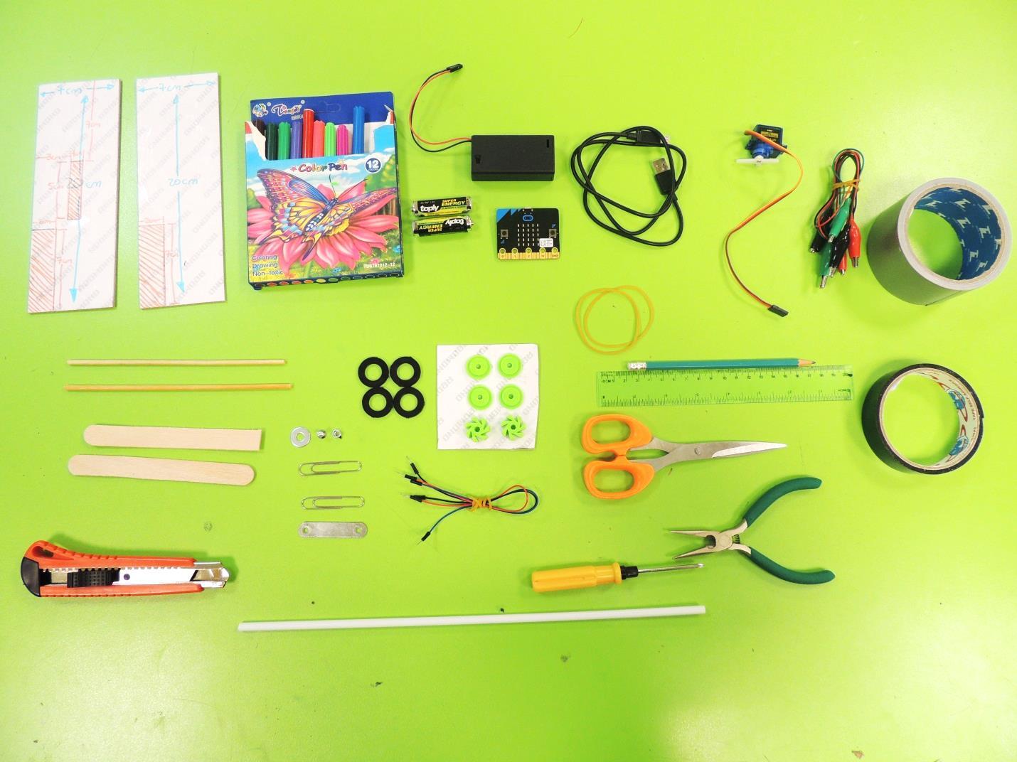
Materials per student/team (2 kids)
- 1 BBC Micro:bit board
- 1 2 AAA Batteries holder with plug for Micro:bit
- 2 AAA Batteries 1 USB cable for Micro:bit
- 1 Servomotor with double-arm horn and screw
- 3 Alligator Test Leads (red, black and blue)
- 3 Jumper wires (red, black and blue)
- 1 Mounting Tape (double-sided, thick, black)
- 1 duct tape roll 2 sheets of balsa wood or hard cardboard (20 cm x 7 cm)
- 3 rubber bands
- 1 round long kebab stick (4mm diameter)
- 1 long plastic hard straw (for balloons)
- 4 rubber washers for plumbing (14mm inner diameter, 24 mm outer diameter)
- 2 big paper clips
- 1 ruler
- 1 pencil
- 1 pair of scissors
- 1 needle-nose pliers
- 1 cutter
- 1 set of color markers
- 1 caliper
- 1 Computer with internet access or Makecode offline editor installed.
- 1 computer per student, with Wi-Fi, access to internet browser and mouse.
- 1 computer for teacher, with the same requirements.
- 1 3D Printer, type: FDM (Flashforge Finder)
- Printing material: PLA of 1.75 diameter
- Tools for 3D printing (needle-nose pliers, spatula, plus tool set included in the 3D printer’s box)
- Extension Cords and Surge Protectors (to provide power for the computers)
- Wireless Internet Connection (essential for the lesson)
Pre-Lesson
- For the first session (CAD), you will need the caliper and one round kebab stick and one rubber washer.
- Make bags with the materials to distribute to each kid on the second session
- Make a prototype of this project, so you can show it to the students.
Day 1: Creating TinkerCAD Accounts:
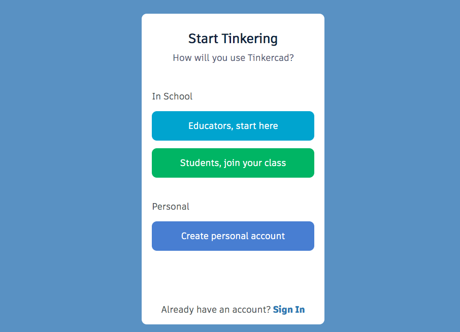
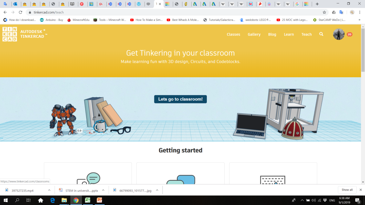
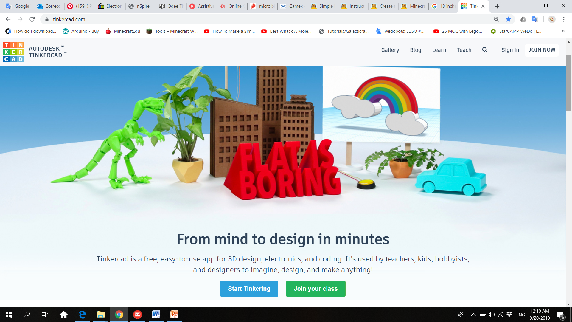
1. Go to www.tinkercad.com and click in “Join now”
2. Click on “Educators, start here”, follow the instructions and open your account
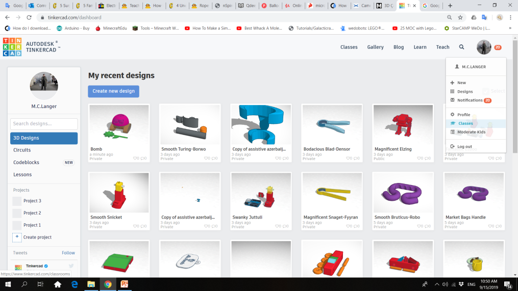
3. To create a Tinkercad classroom for your students, go to your profile and click “Classes”
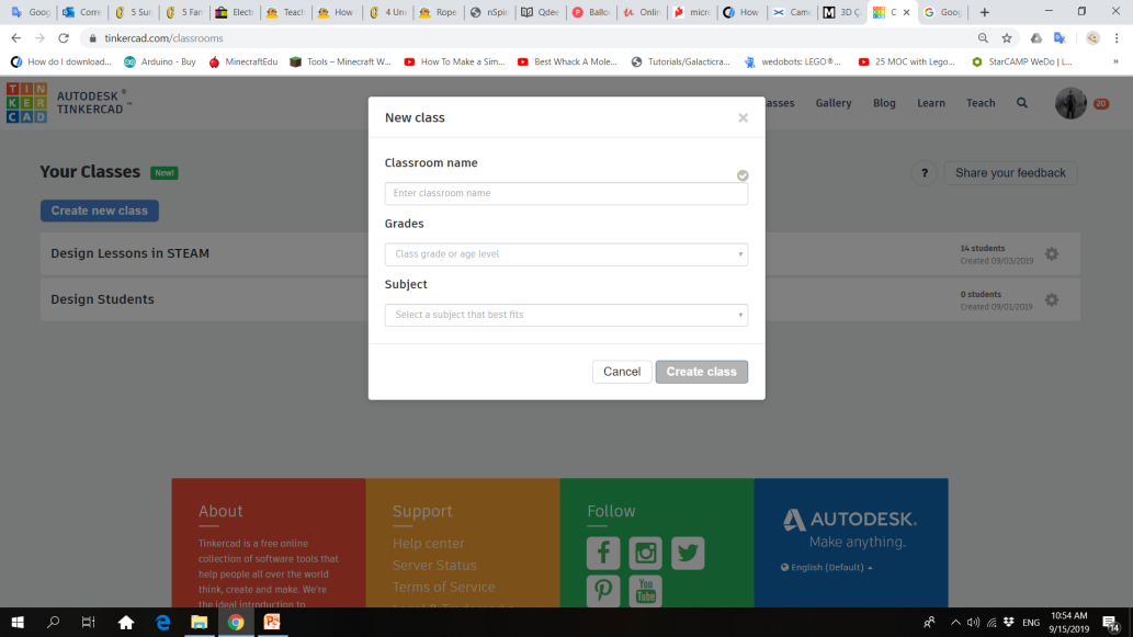
4. Click “Create new class” and fill the form with the information of your group
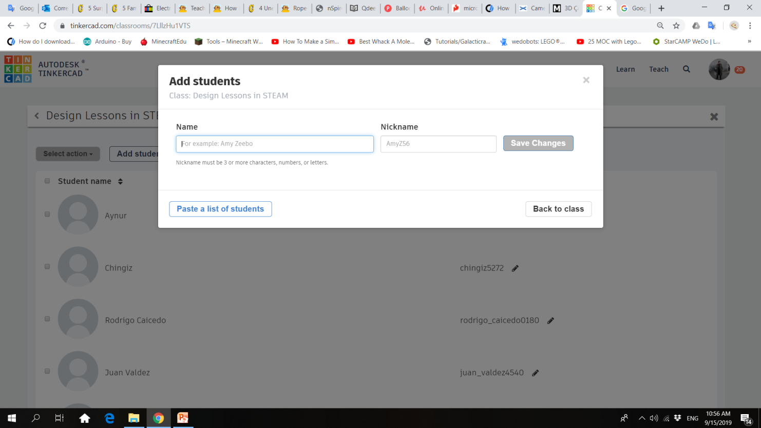
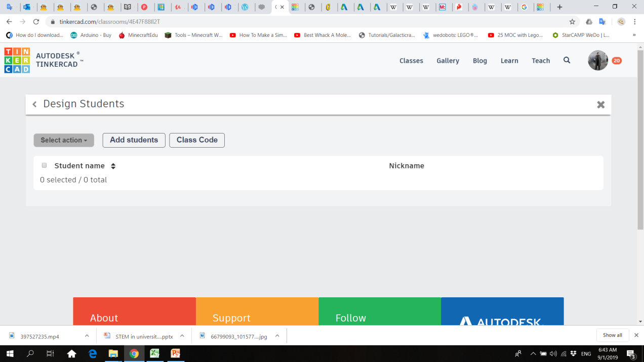
5. Add the names and nicknames of your students. You can also copy and paste a list of students.
6. Click on “Teach” and then, click on “Let’s go to classroom”
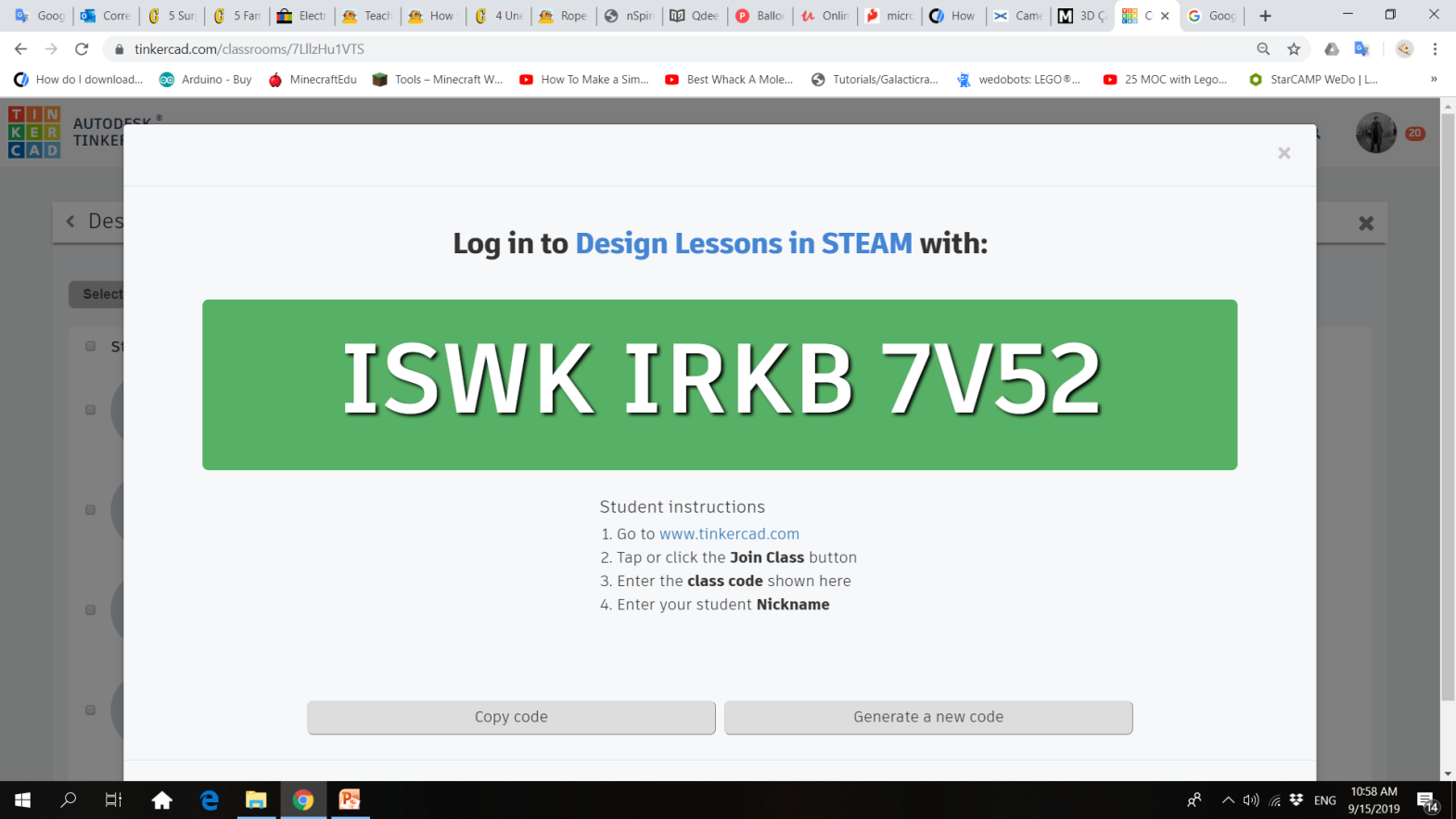
7. Go to “Class Code” and share it with your students
8. To enter to the virtual classroom, students must follow the instructions and enter your Class Code.
9. Students must click on ”Join your class” and introduce their code and nickname
10. To review your students’ designs, go to your class and click on their names to check their designs.
Designing Mechanical Parts
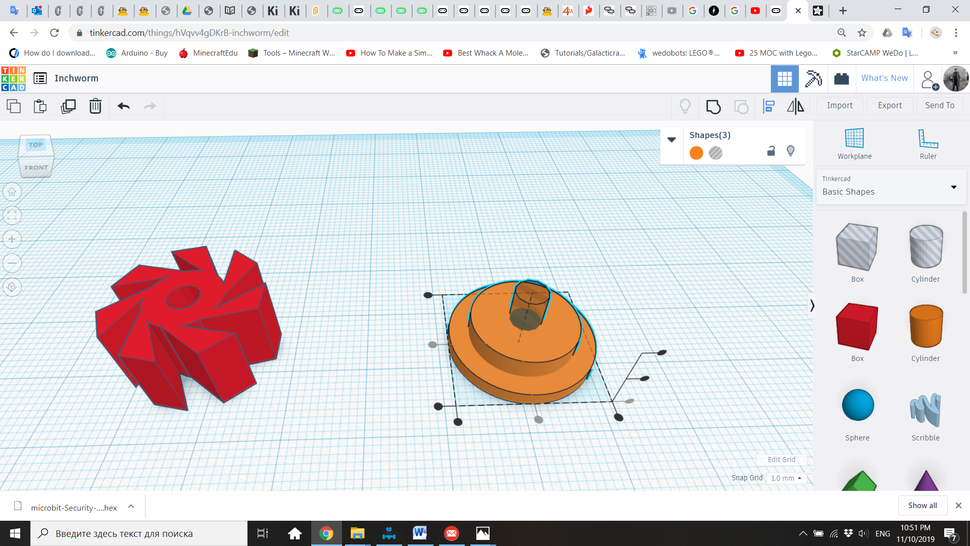
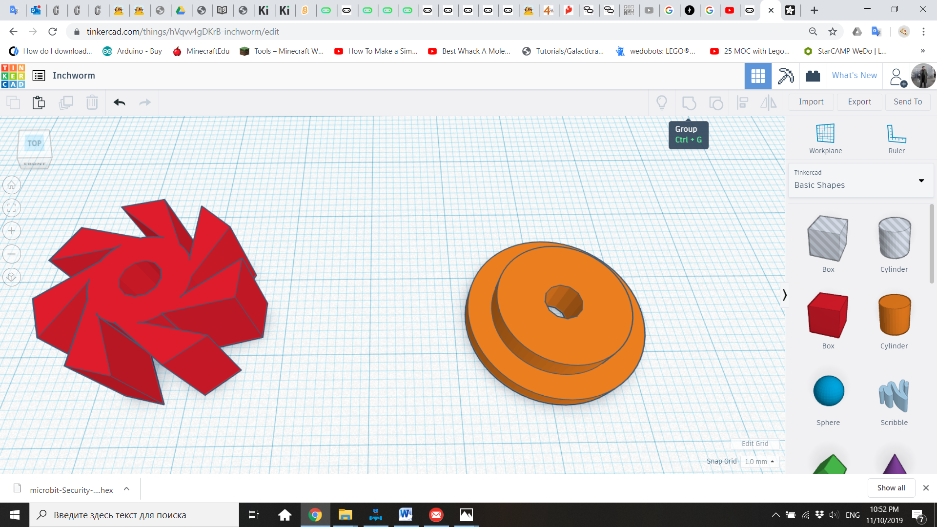
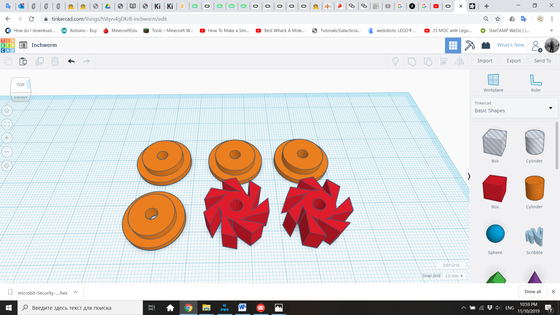
1. Welcome the students to the CAD classroom, and review with them the introduction and concepts. Inform them that this project will take them two sessions, being the first one the design of some mechanical pieces, and the second session the building and programming of their robot. Also ask: Does anyone remember what CAD and 3D printing mean? What are the applications of CAD and 3D printing in human life?
2. Have everyone open their computers and then open the internet browser and go to Tinkercad. If Tinkercad has been saved as the homepage, students only need to open the internet browser, otherwise, direct students to the address www.tinkercad.com.
3. Instruct everyone to enter to the Tinkercad “class” as described in the 3D Printing Classroom Setup (NOTE: This account is only for classroom purposes, and projects will be there as long as the teacher keeps the class group open. If a student wants to create personal projects, he must open his own Tinkercad account.)
4. Once all of the students have successfully log in into their accounts, tell them that they are ready to begin using Tinkercad. You and the students must click in “Create new design”.
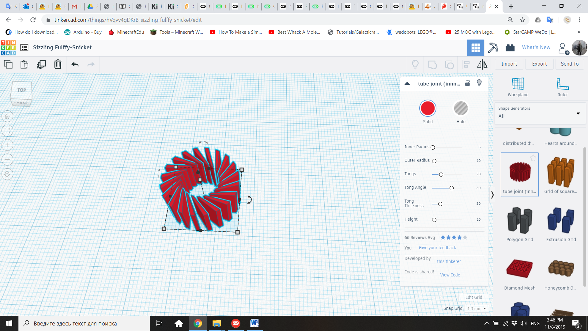
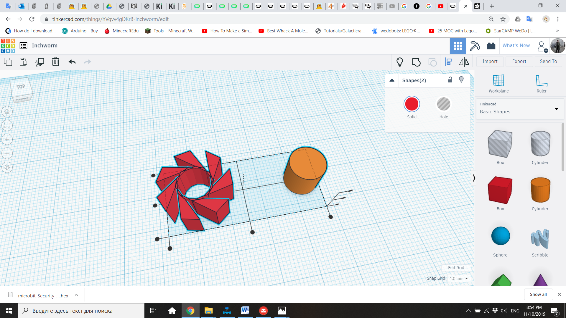
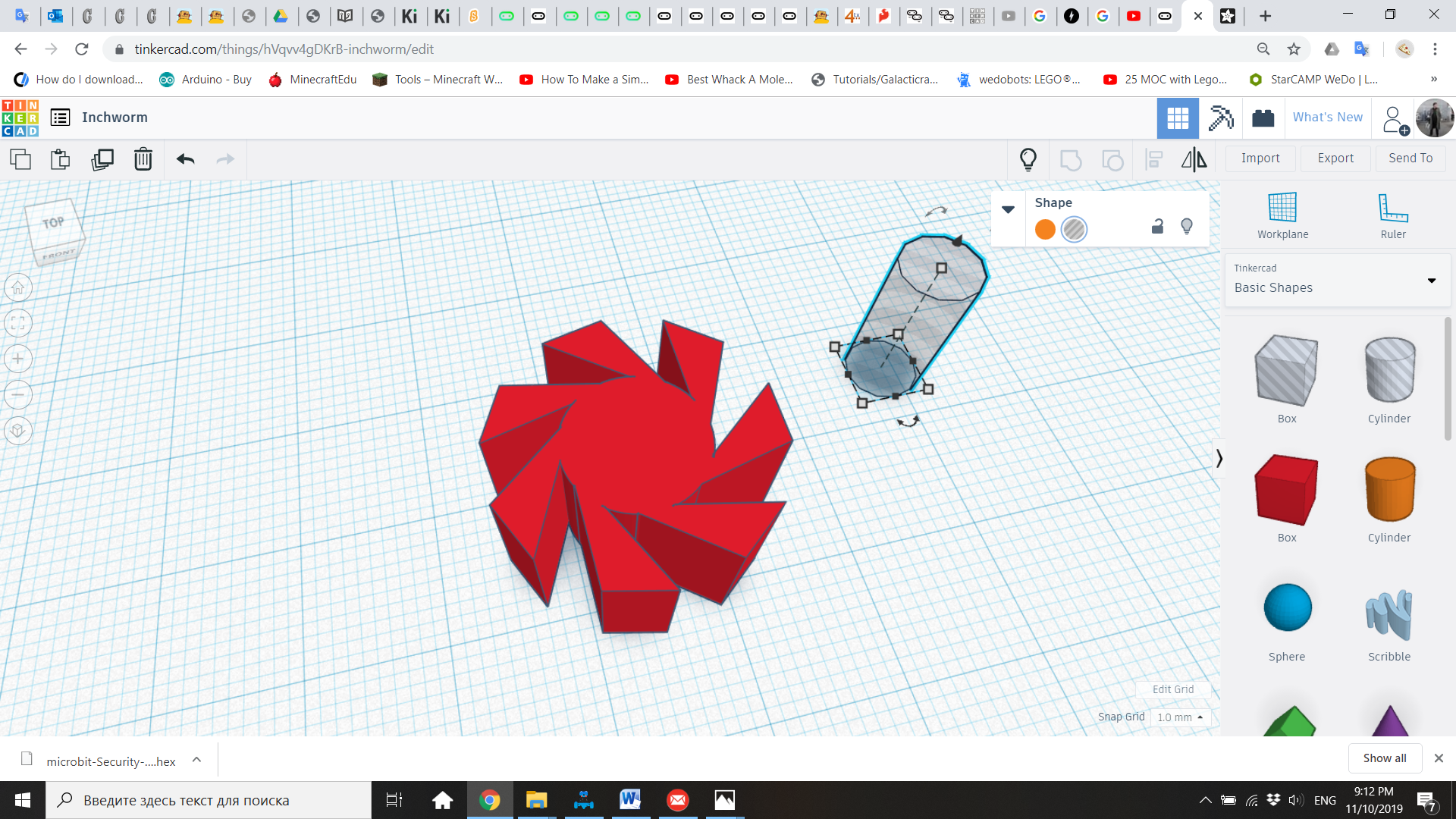
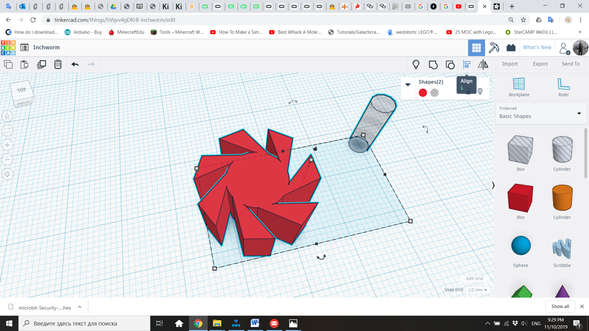
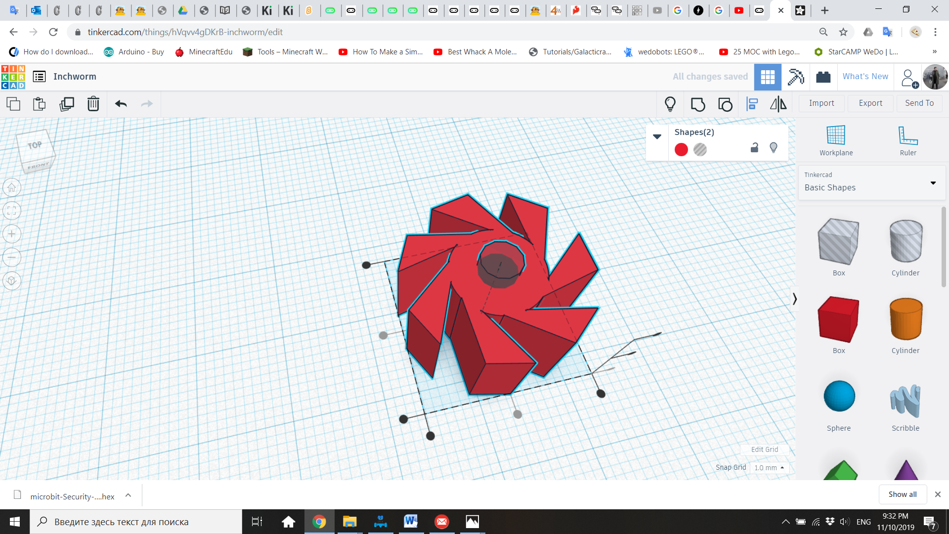
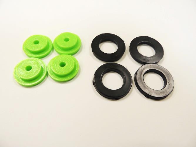
5. Explain to the students that we need to create 6 pieces: two gears and 4 wheels. The importance of the gears is that they will allow the wheels to go in one direction, but not in the other one. Without these special gears, the Inchworm will be moving in the same place without advancing. To create these gears, go to “Shape Generators – All” and bring a Tube Joint.
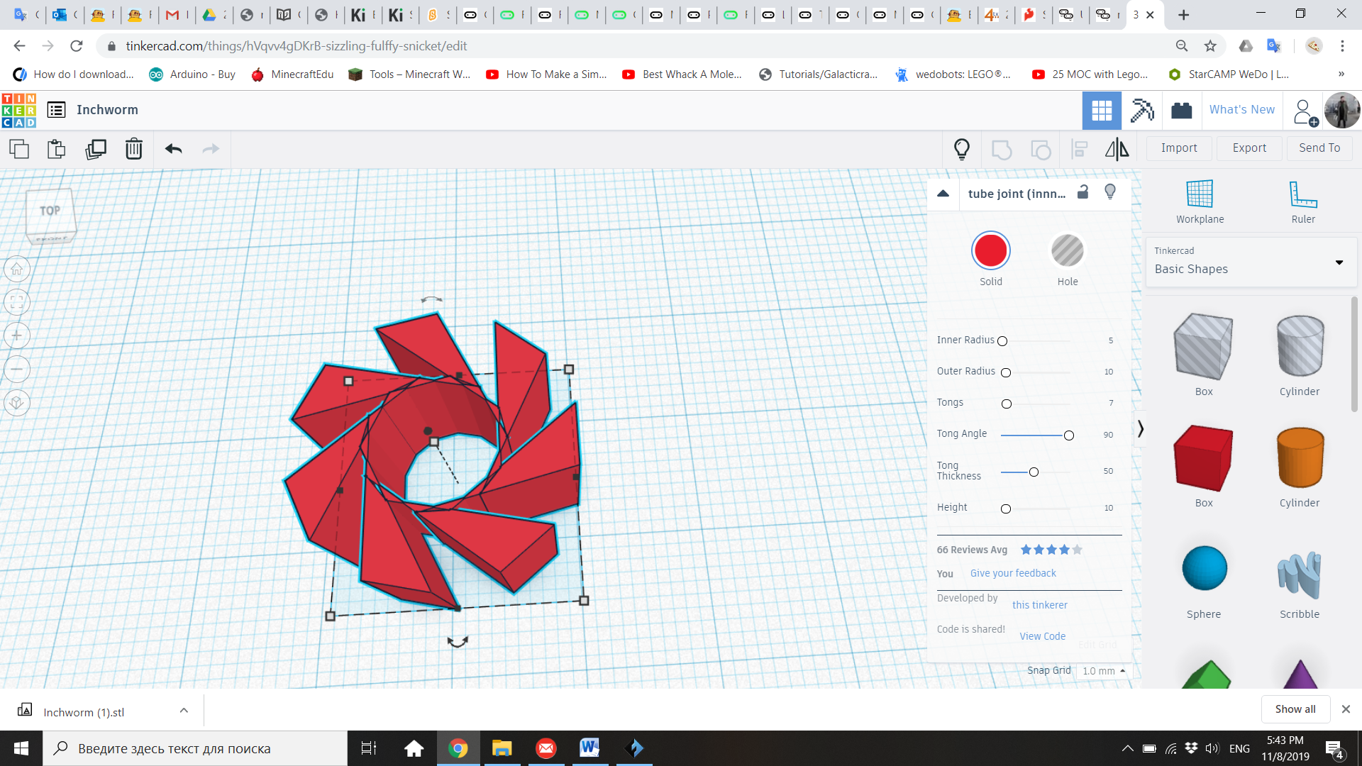
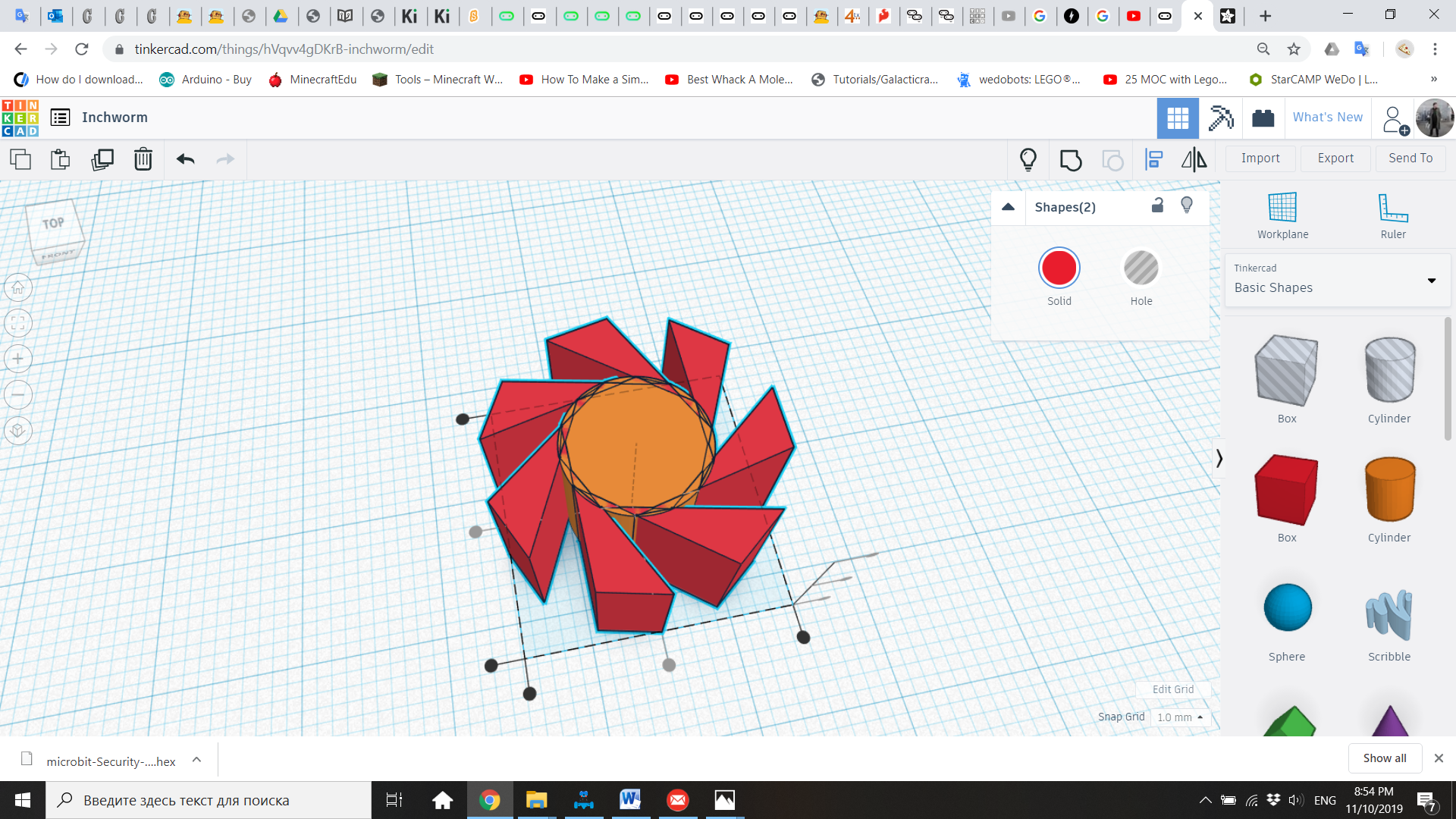
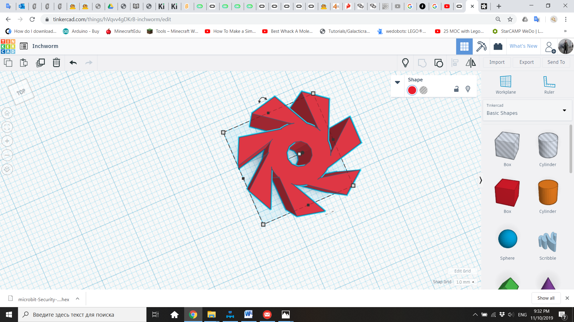
6. In the Inspector, modify the properties of the Tube Joint, so it will have 7 cogs. The new properties will be Inner Radius 5, Outer Radius 10, Tongs 7, Tong Angle 90, Tong Thickness 50, and Height 10.
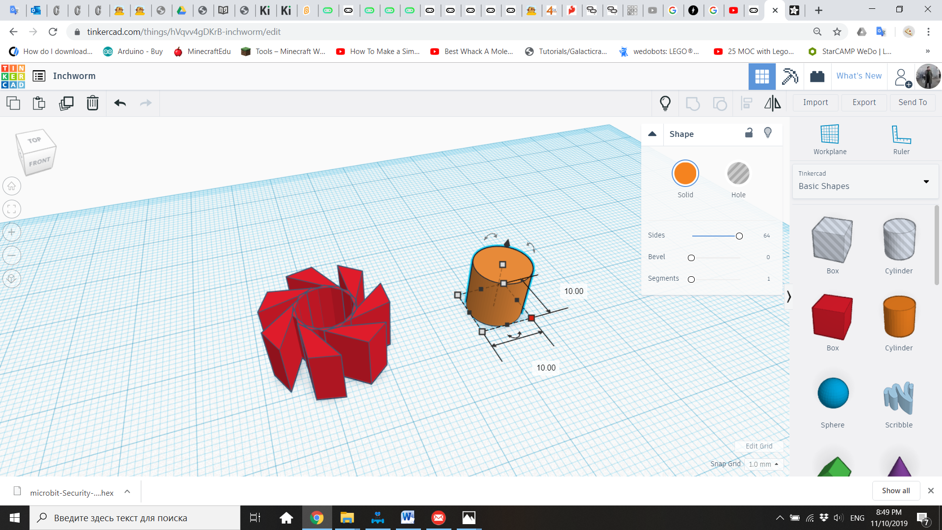
7. From “Basic Shapes”, bring a cylinder of 10 x 10 x 10
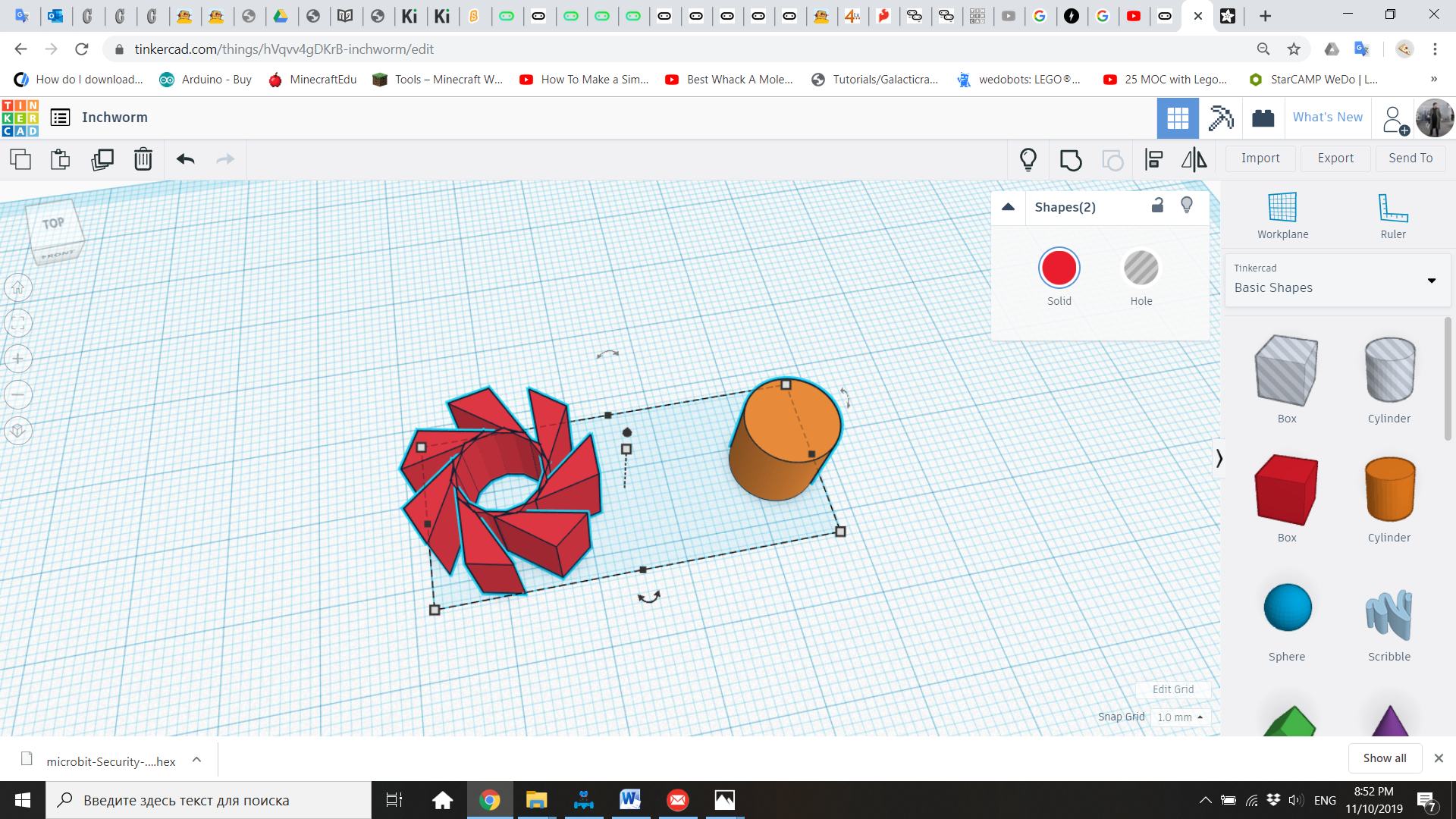
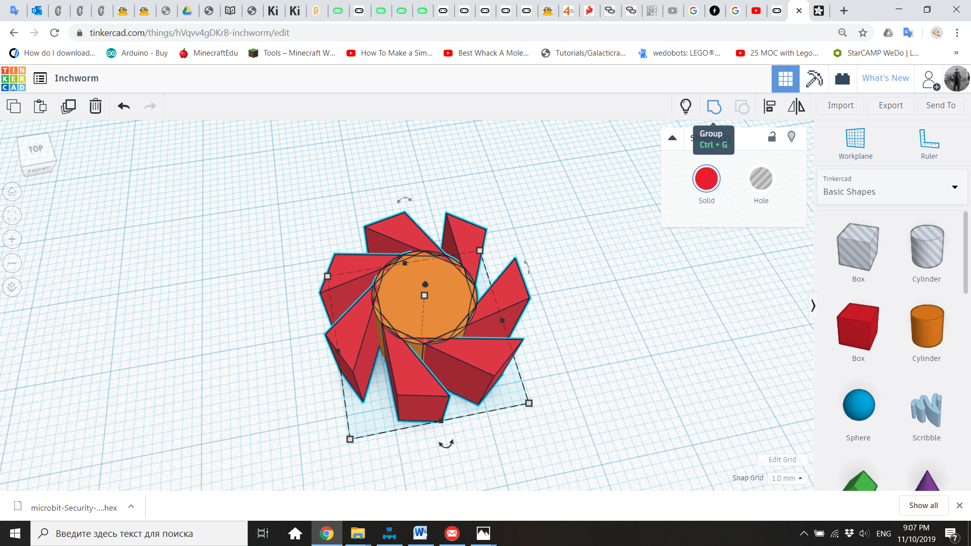
8. Select both shapes and use the “Align” tool to bring them together and make them concentric.
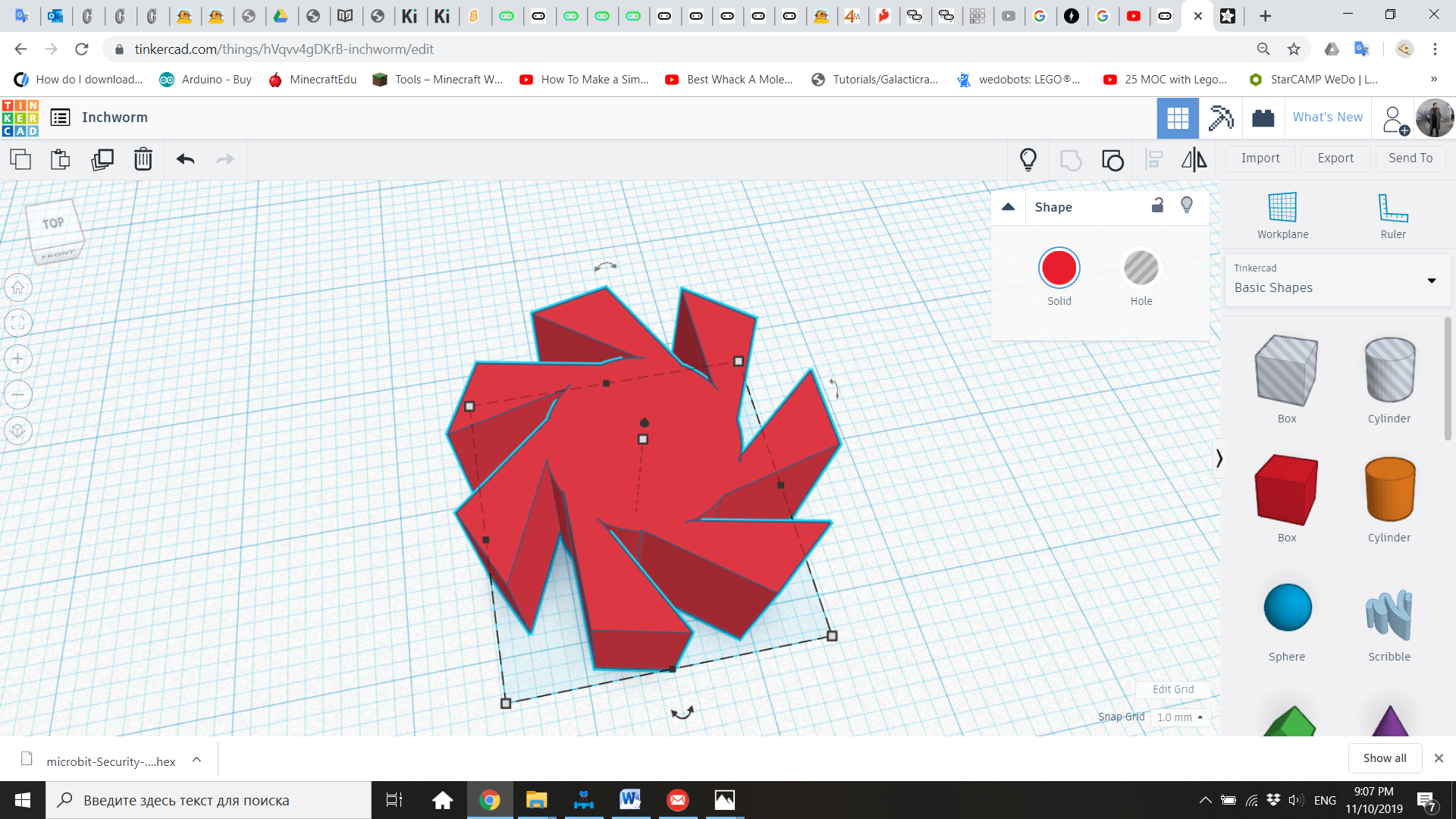
9. Use the “Group” tool to transform both shapes into a single one.
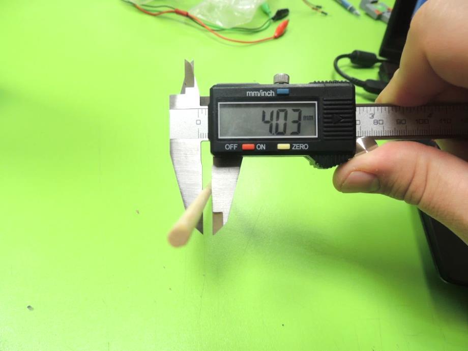
10. Now we need to create a shaft in the center of the gear, where the round kebab will be inserted. Bring a hole cylinder from the “Basic Shapes” menu. Ask kids “how can we measure the cylinder’s diameter in an accurate way?” Consider that, if the hole is too big, the gear will be loose and there won’t be any traction to be transmitted to the wheels. If the hole is too narrow, the stick will not be able to enter.
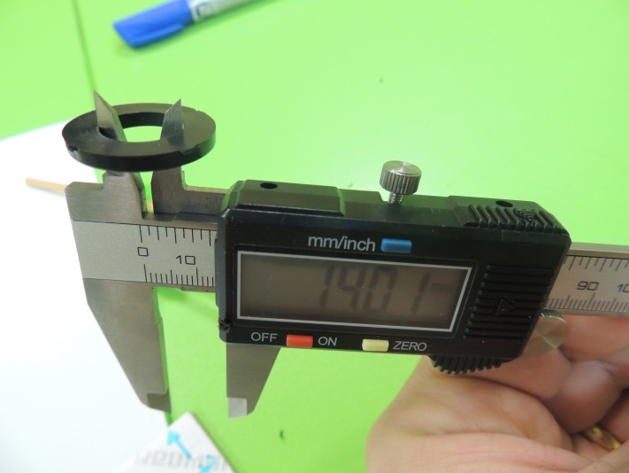
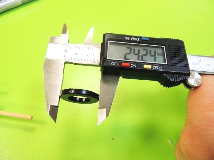
11. The answer is the Caliper, a tool that is great to measure diameters. Show kids how to use this tool, to get a proper measurement of how thick is the kebab stick. The one used in this project is 4.03mm.
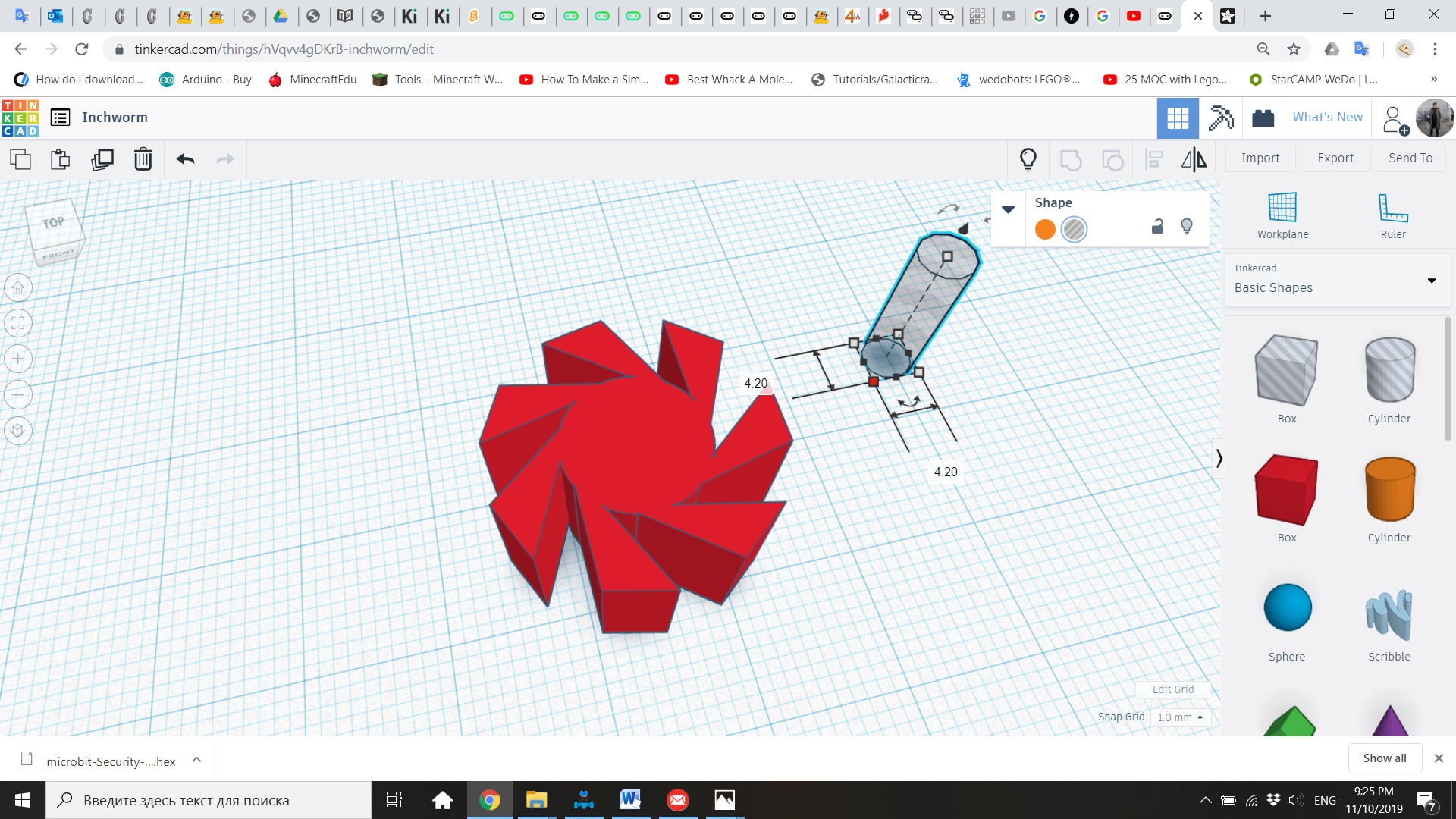
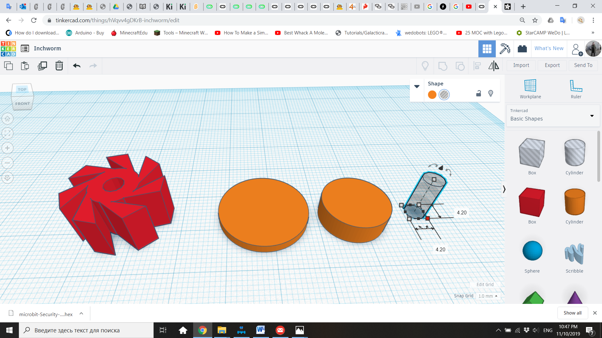
12. The diameter of the cylinder hole will be 4.2 mm, considering that there is a tolerance of more or less 0.1mm between the design and the printing.
13. Now align both shapes to the center, and group them to create a single shape.
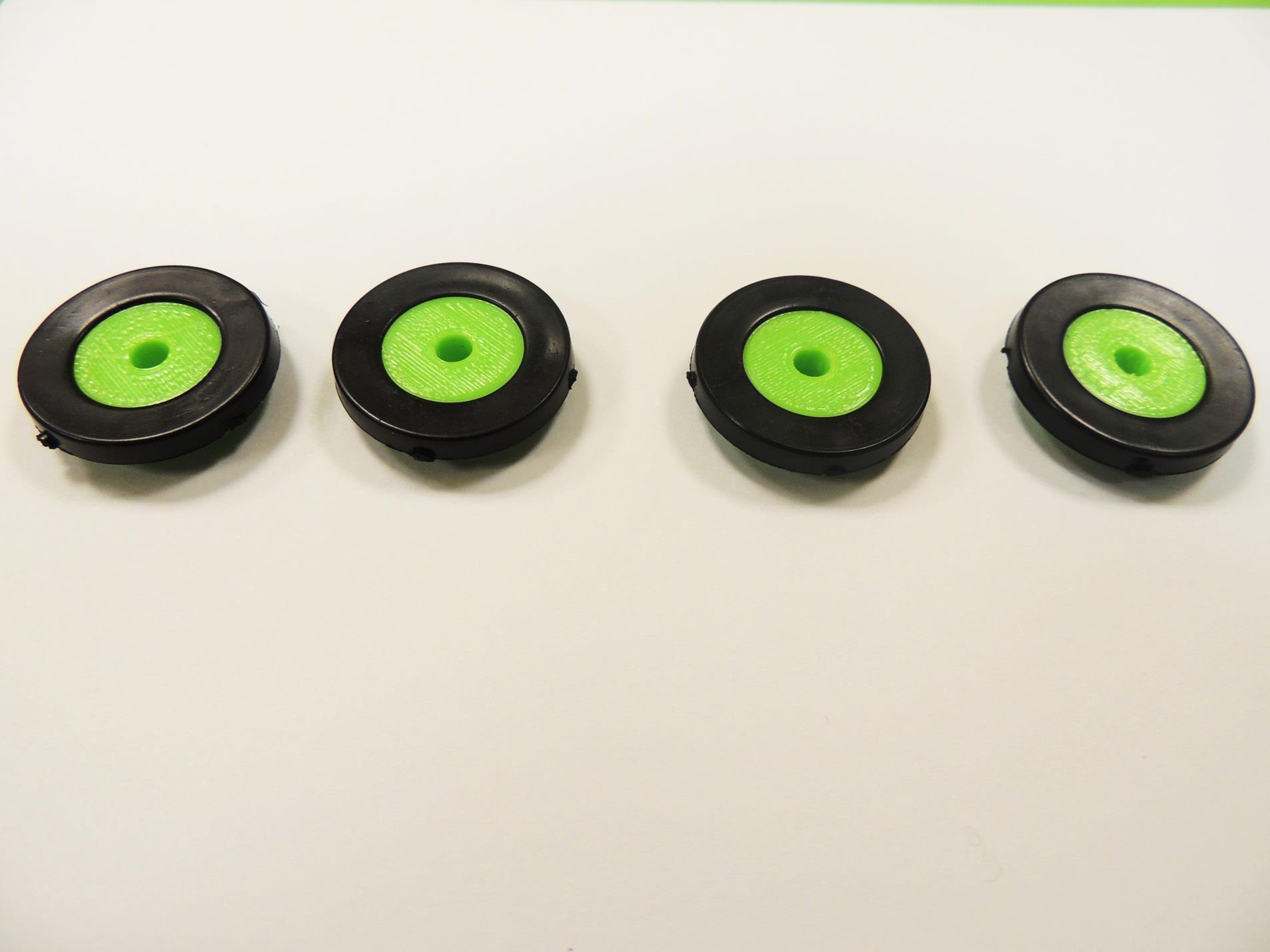
14. Now we will design the wheels. We need to consider that not only the kebab stick must fit tightly in the center, and we already have that measurement. Also, the rubber washers must tightly fit in them to work as tires.
15. This time, we will use the caliper to measure the inner diameter (hole) and outer diameter of the rubber washers. That way we can design a suitable plastic wheel.
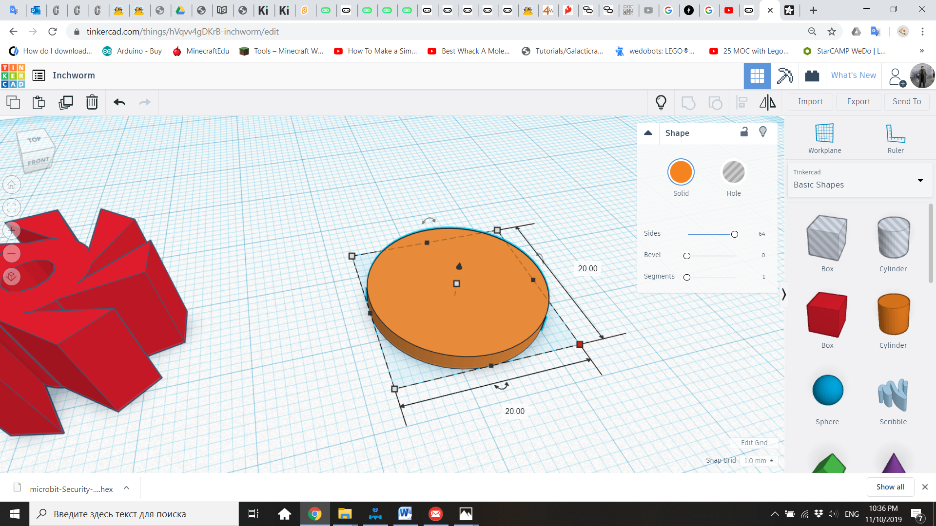
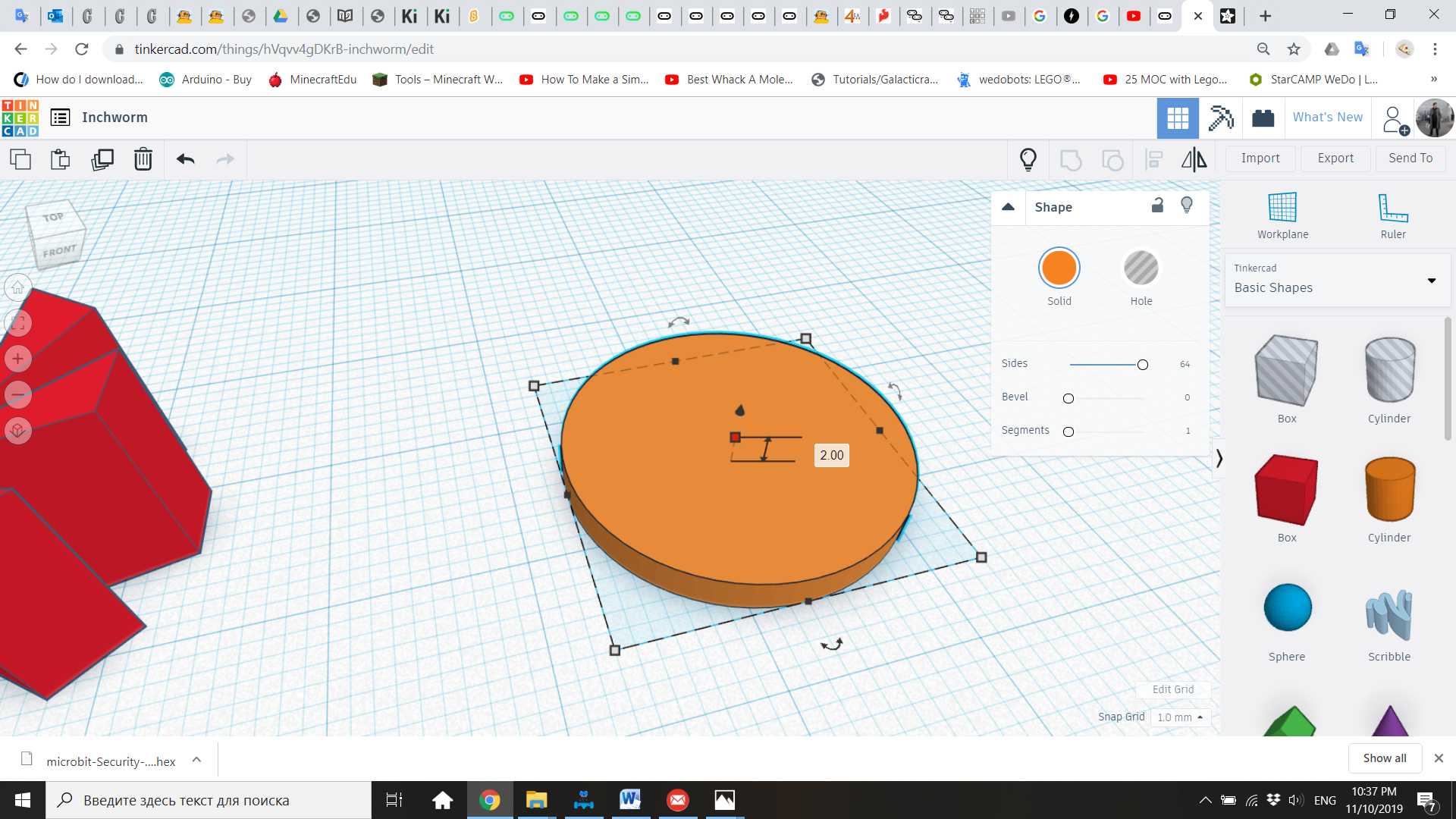
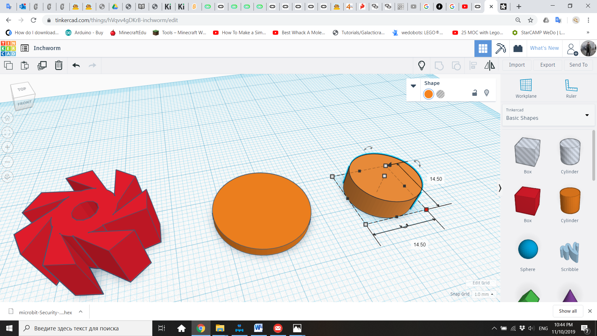
16. Bring to the workplane a cylinder of 20mm diameter and 2mm height
17. Now, bring another cylinder, this time of 14.5mm diameter and 5mm height.
18. For the shaft, create a hole cylinder similar to the one for the center of the gear (4.20mm diameter x 10mm height)
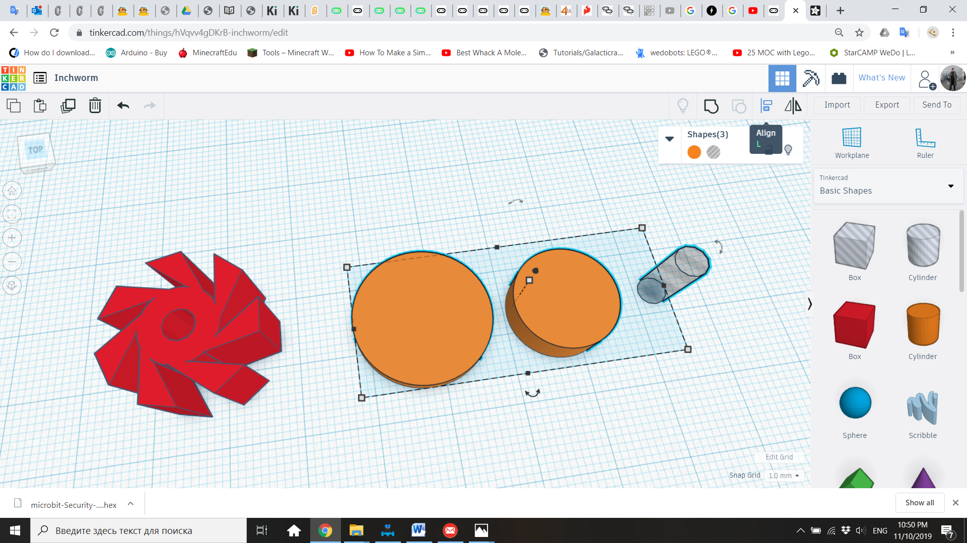
19. Select and center align these three cylinders. Then group them to create a single shape.
20. Now with the gear and the wheel ready, we need to create one duplicate of the gear and three extra wheels. Use the Duplicate function (CTRL-D), and then use the arrow keys to drag the new copy out of the shape.
Slicing and Printing
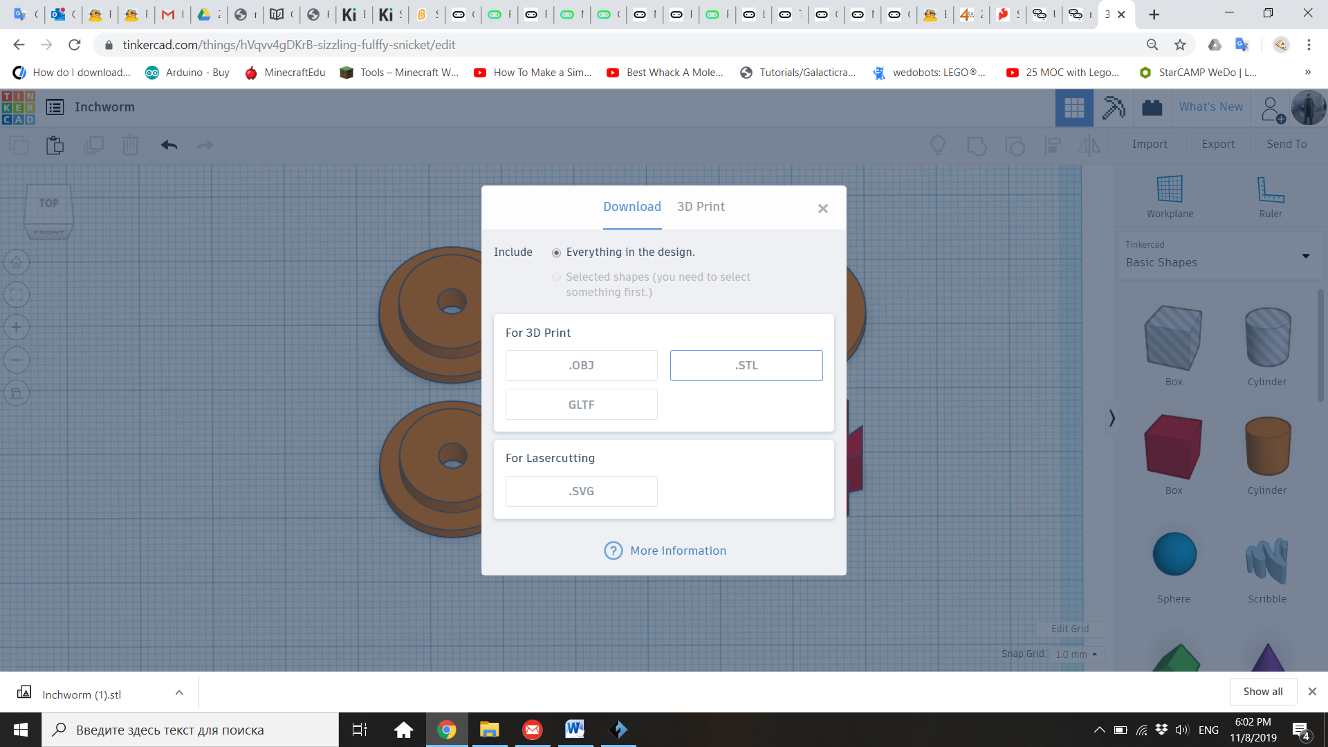
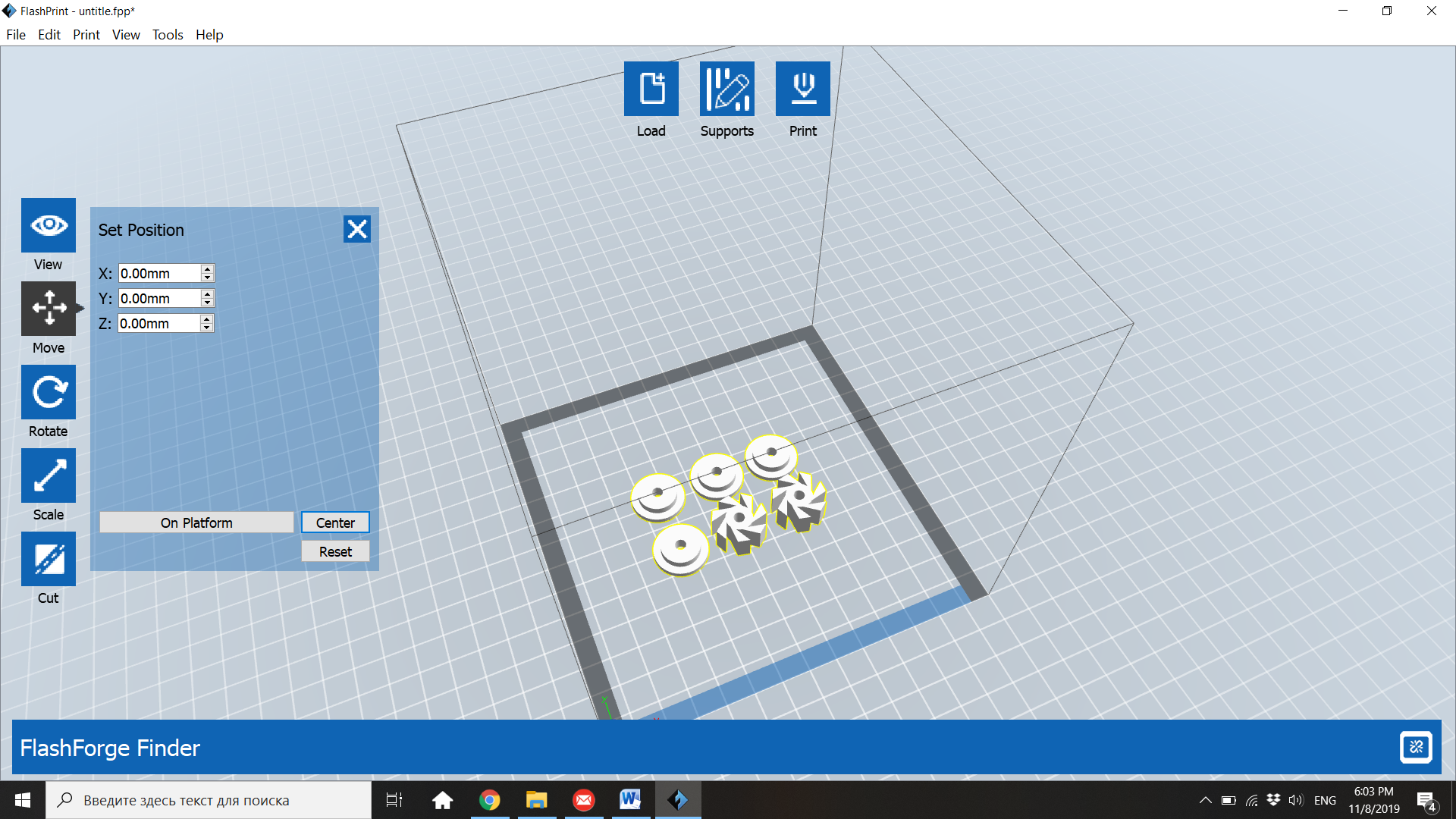
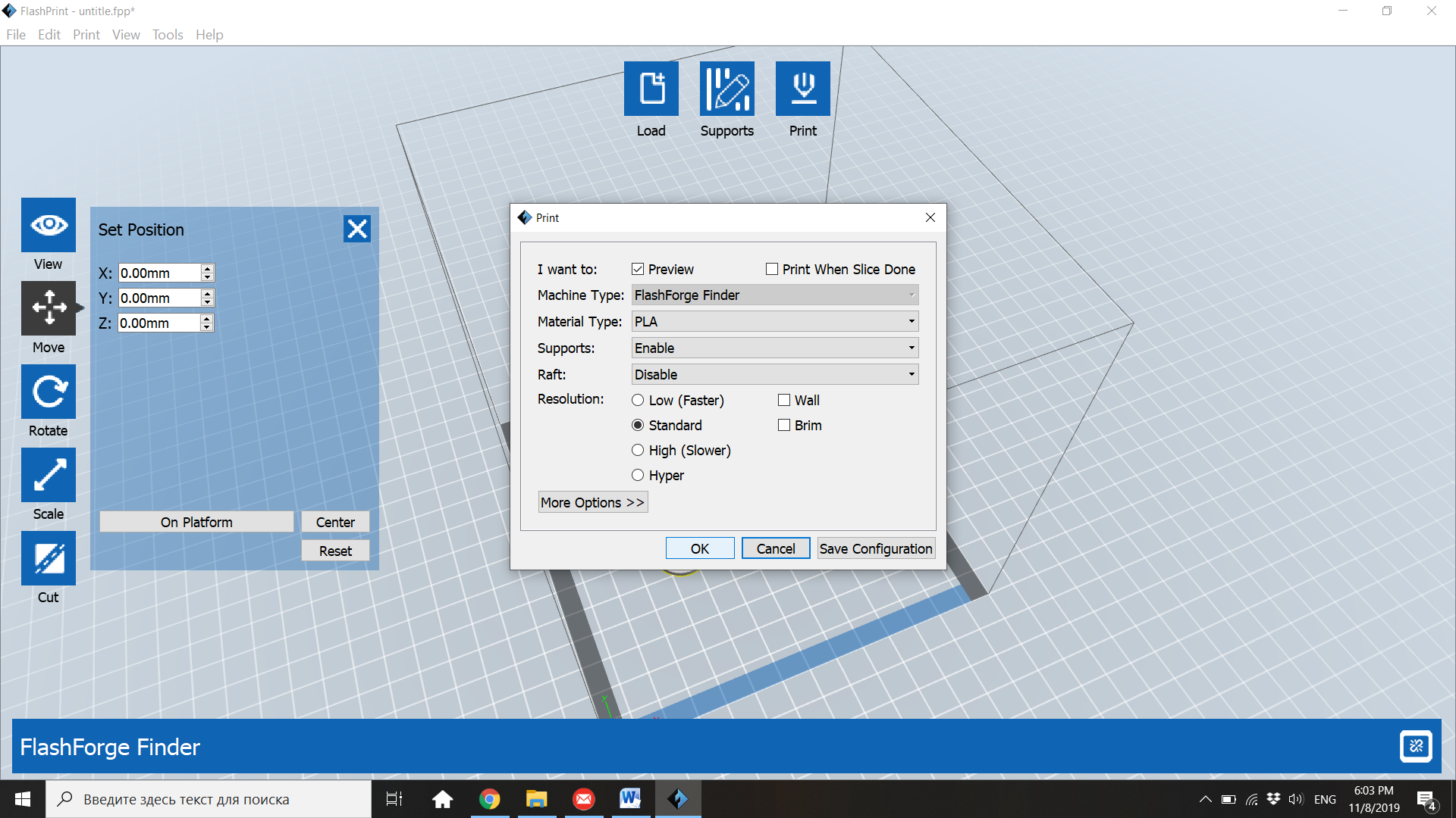
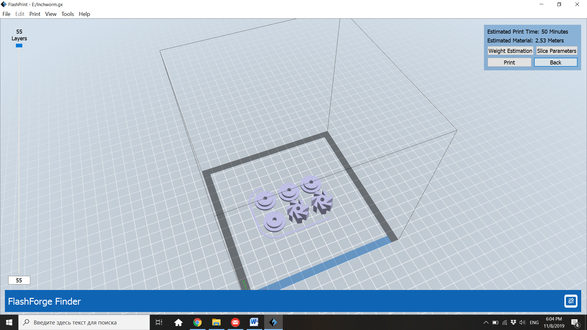
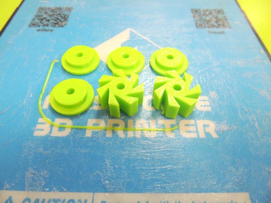
21. To print the 3D model, click in “Export” (top of the Shapes Menu) and select “Everything in the design” and “.STL” It will download the file to you Downloads folder.
22. Open Flashprint, the slicer software for Flashforge Finder. You can download it from the site https://www.flashforge.com/download-center, select the option “Software Download and select the last version of Flashprint for Windows (32 or 64, depending of your computer)
23. Select “Load” and find your .STL file to print. With “Move”, place your model in the center of the printing platform. WARNING: Remember that you may not reduce size it with “Scale”, or all the dimensions will be affected and the 3D printed components will not be compatible with the kebab sticks and the rubber washers.
24. You don’t need supports for this design, so click directly in “Print”. Choose the Standard resolution, click OK and save the new file .gx in a USB.
25. Printing the mechanical parts for the classroom will take several hours. You will need to keep printing the parts afterhours, and have them ready before the second session. If there is still time, you can start working on the Micro:bit code. At the end of the lesson, remind students that on the next session they will have their parts ready and they will combine them with the Micro:bit and the other materials to create a robot.
Day 2: Micro:bit Code
26. Welcome the students and inform them that today they will build their Inchworm robot, using the 3D printed parts designed on the previous lesson and other materials. Give them the pockets with materials and show them your prototype.
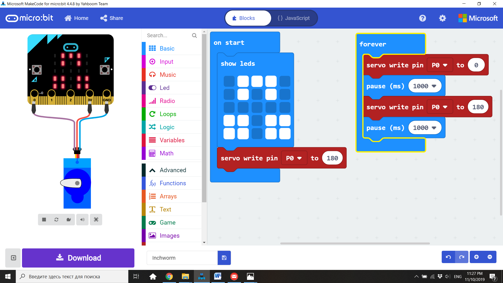
27. This is the basic program for the Inchworm. The servo will start in the 180 degrees position, and then a forever loop will alternate the servo between 0 degrees position and 180 degrees position. That will give the characteristic open/close movement of the robot. Kids will need to test and improve this program, until they get the most efficient servo movement.
Inchworm's Body
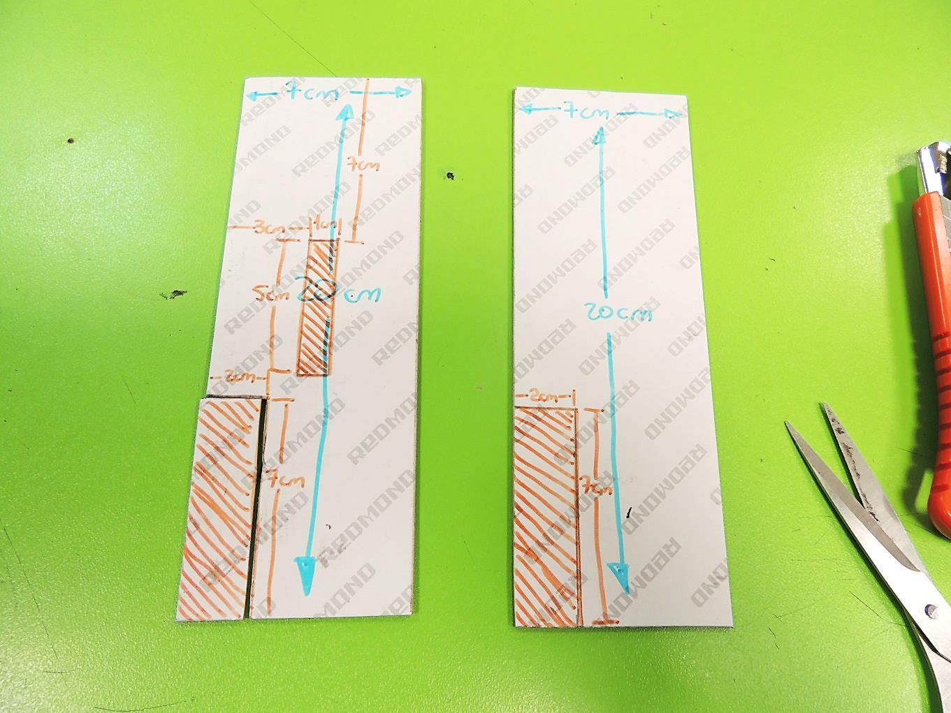
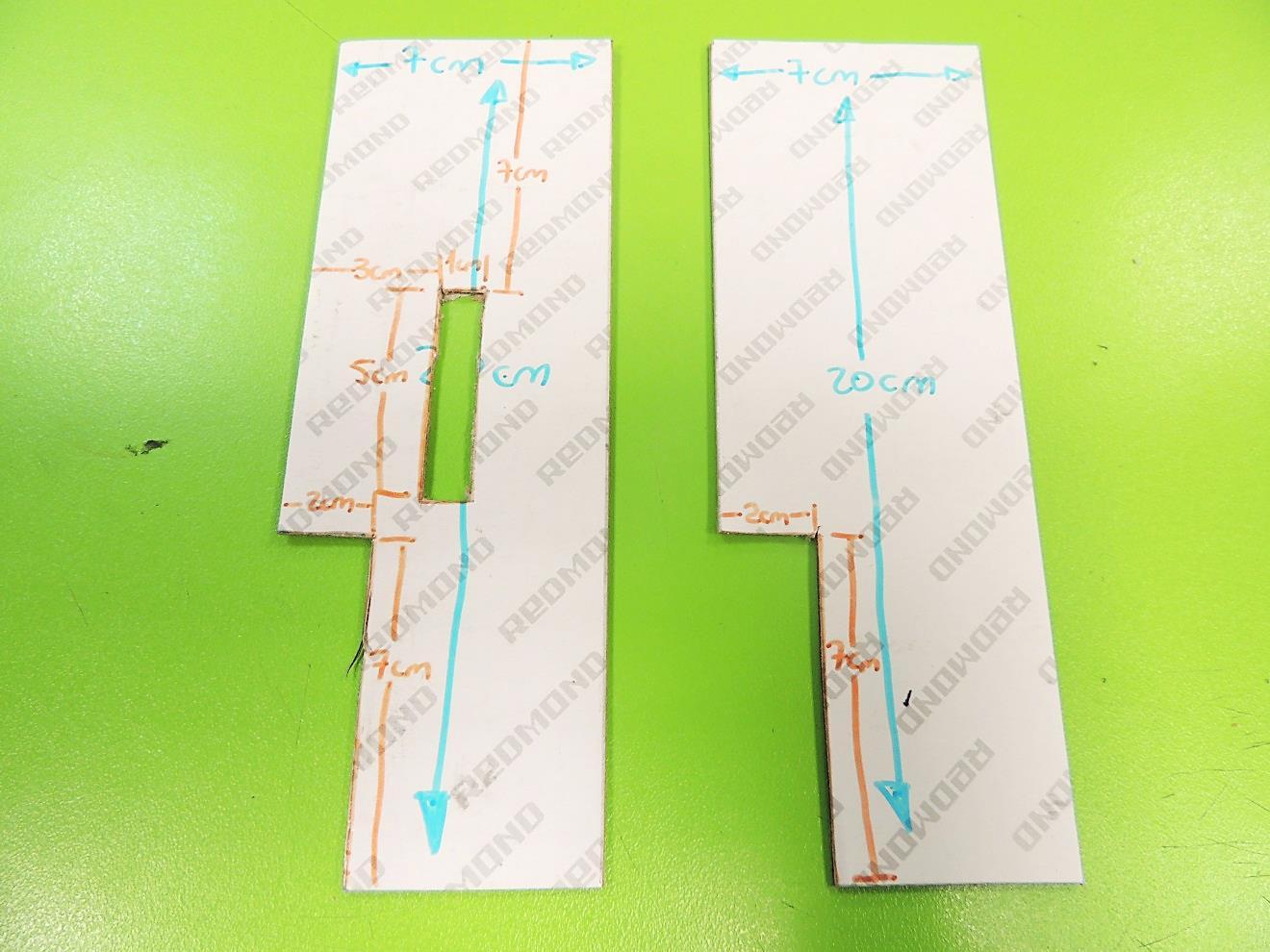
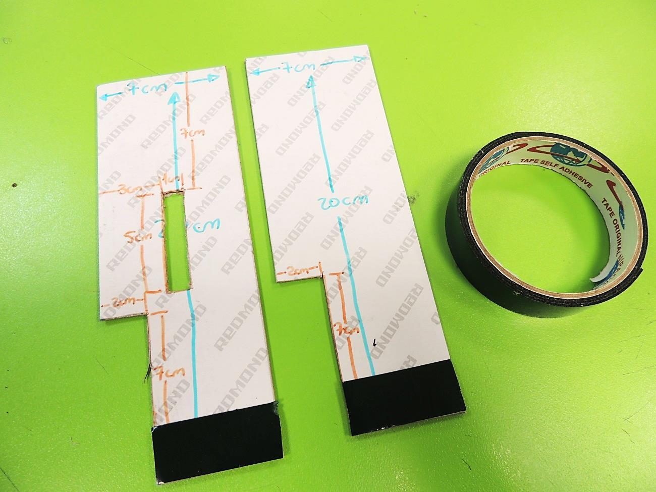
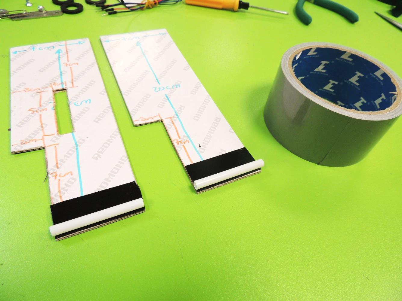
28. Now we will start assembling the robot. Bring both 7cm x 20cm hard cardboard tablets. In both of them mark a 2cm x 7cm rectangle at the bottom-left corner. But only in one of the tablets, mark a 5cm x 1cm in the center, 7cm away of the top and 3cm away from the left border.
29. Using scissors, a cutter and a ruler, carefully cut the rectangles from both tablets.
30. Stick a piece of mounting tape on the bottom border of the tablets.
31. Take the hard plastic straw and cut two segments of 5 cm each.
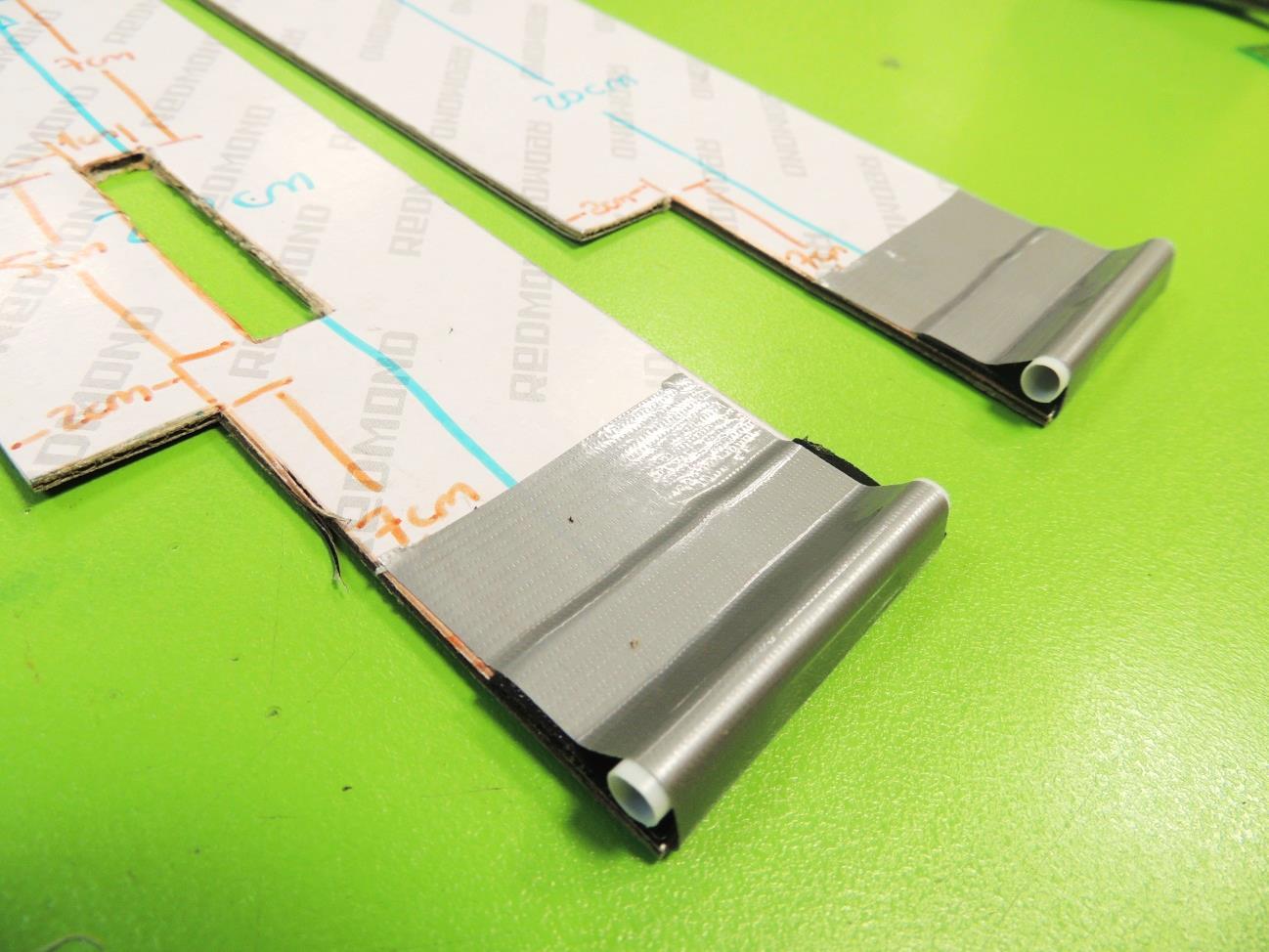
32. Peel the mounting tape and stick the straws to them. Also, fasten the straws with duct tape for a firm attachment.
Wheels and Axles
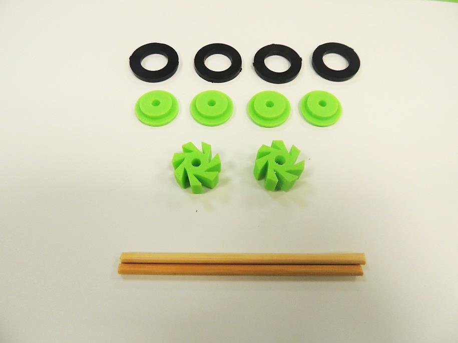
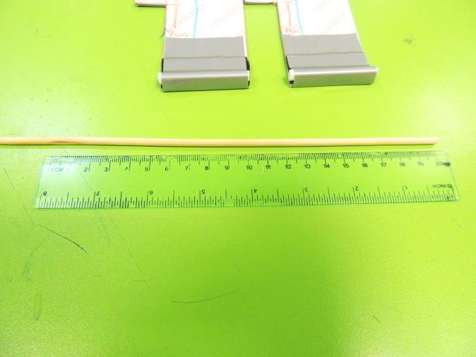
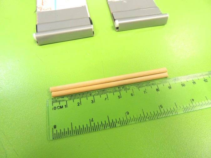
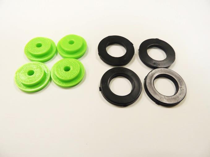
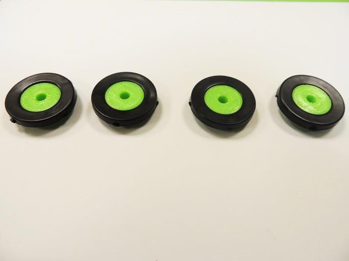
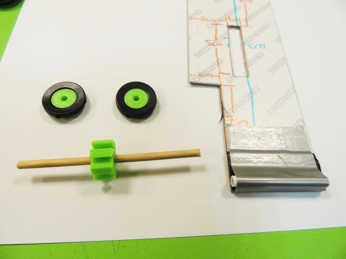
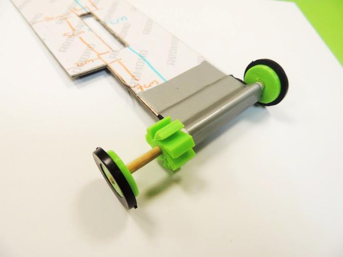
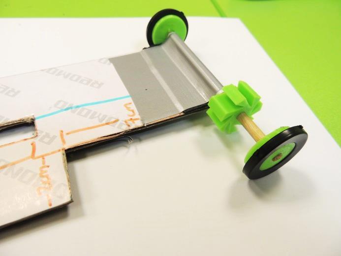
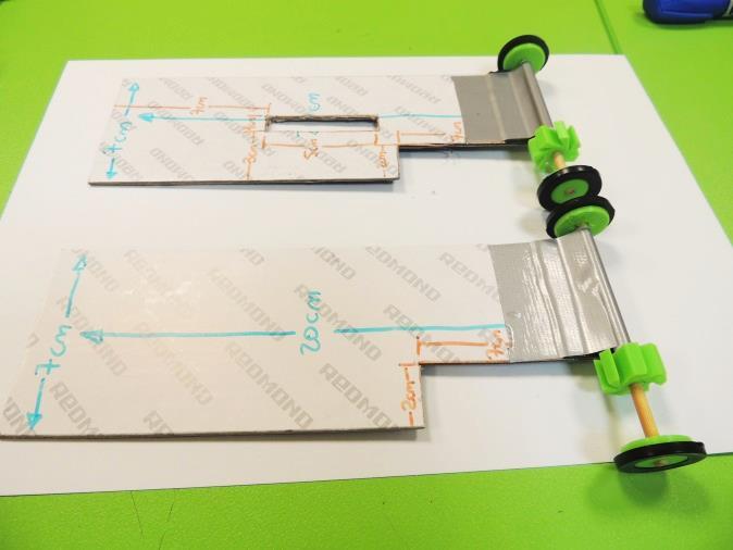
33. Take the round kebab stick and cut two completely straight 9cm segments
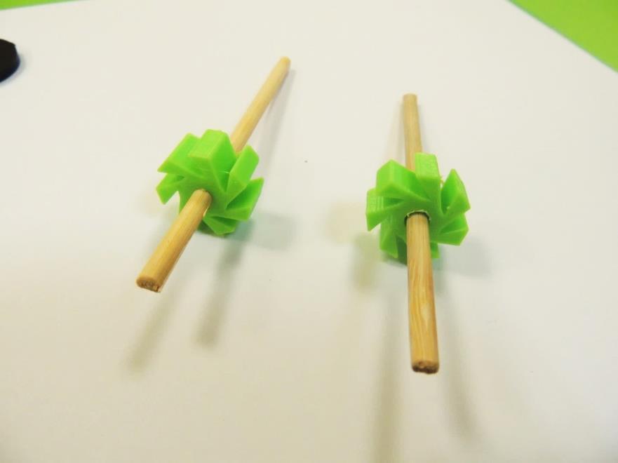
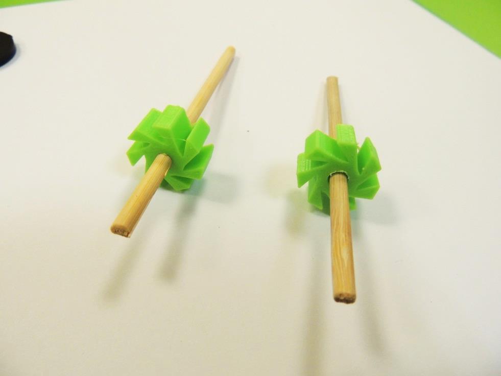
34. Let’s integrate the 3D printed pieces to the build. Insert the kebab sticks through the gears, and attach the rubber washers to the wheels.
35. Insert the kebab stick through the straw and attach the wheels to each end of the stick. If for some reason the center holes are too narrow, you can carefully enlarge them a bit using pointy scissors. On the opposite, if they are too loose, you can add a drop of glue at the test/improve stage, being careful of not jamming the rest of the mechanism.
Stopping Mechanism
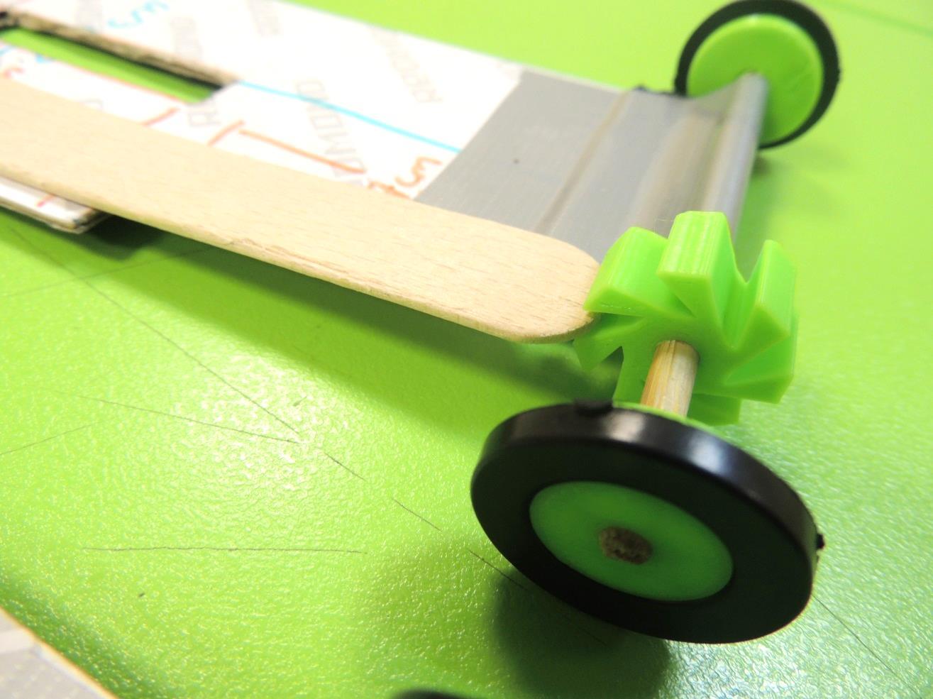
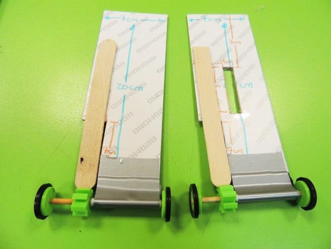
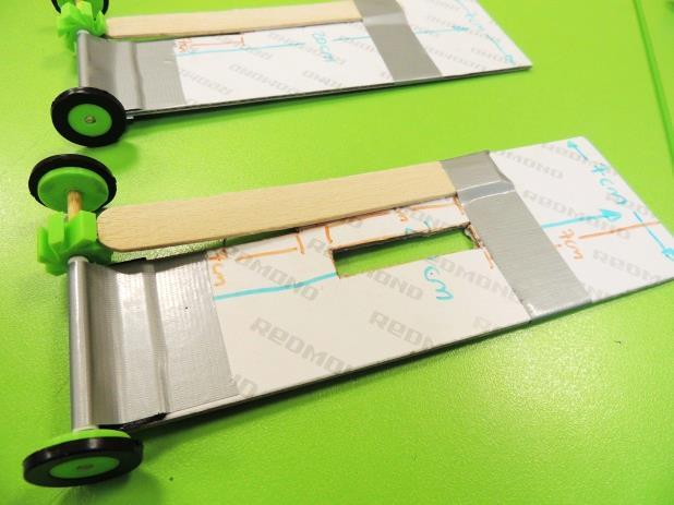
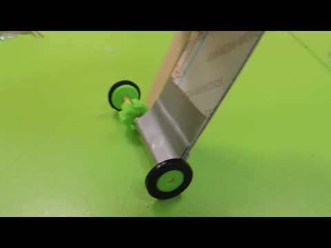
36. Bring the craft sticks and place them in a position where the gear can smoothly rotate in one direction, but gets stuck when tries to rotate to the opposite one. Stick the top end of the craft sticks using only half of a duct tape strip. Be aware that probably you will have to do some troubleshooting of this specific step at the test/improve stage, because sometimes is tricky to find the perfect position of the craft stick and the right placing of the gear on each axle.
Body Articulation
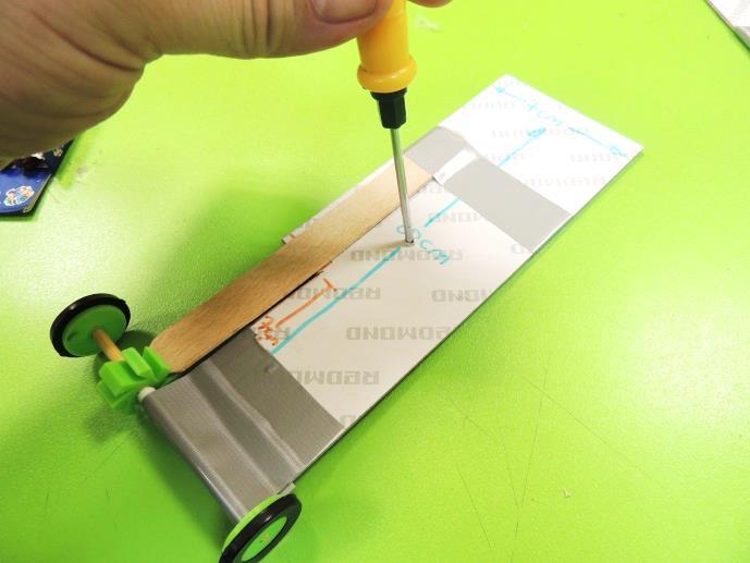
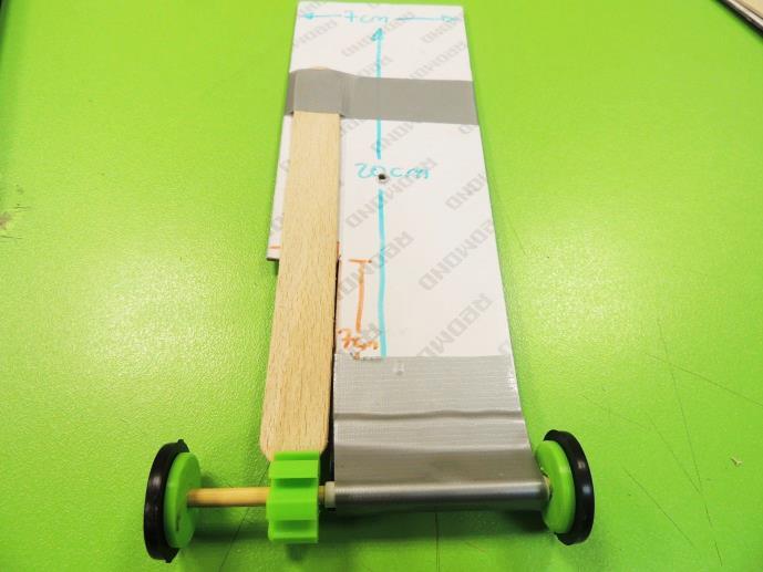
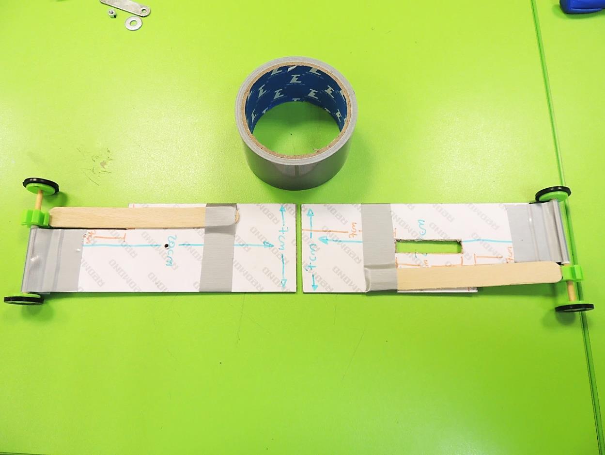
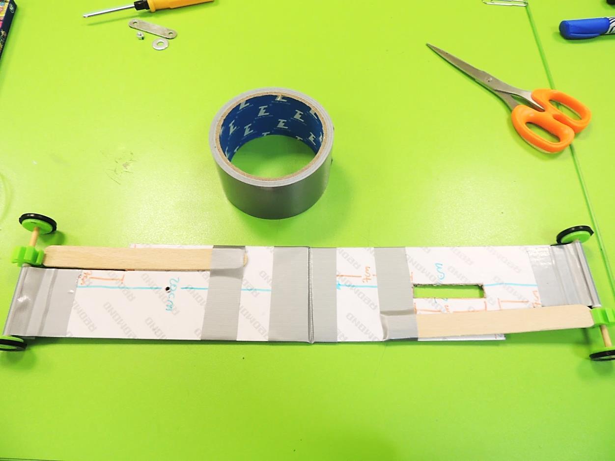
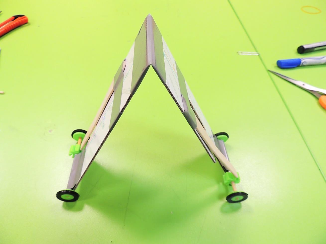
37. Using a screwdriver or any other pointy tool, open a little hole in the center of the cardboard tablet with no rectangle cut.
38. Join the top sides of both tablets, using duct tape. It must be a bendable joint, so it can act like a hinge.
The Wire
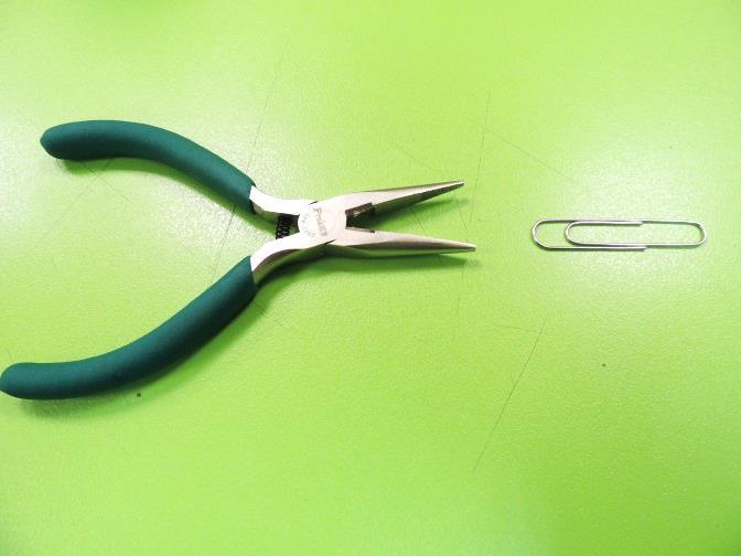
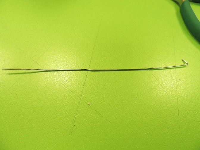
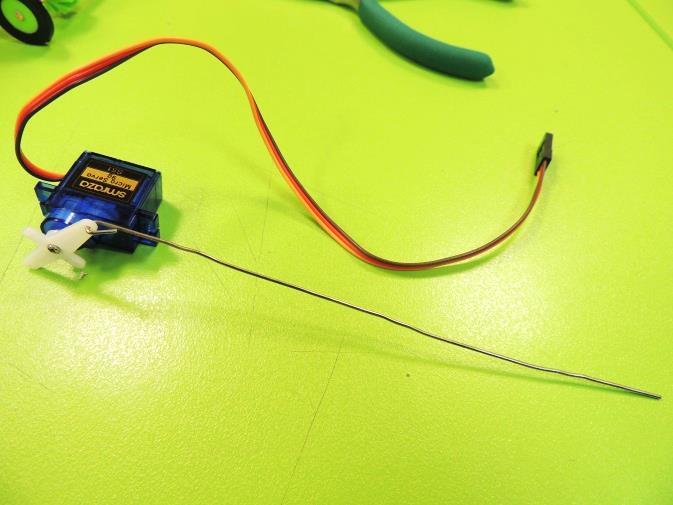
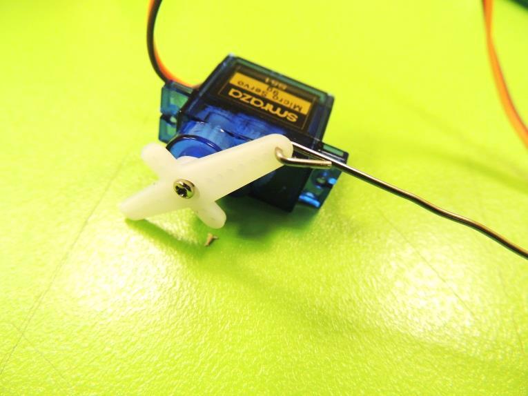
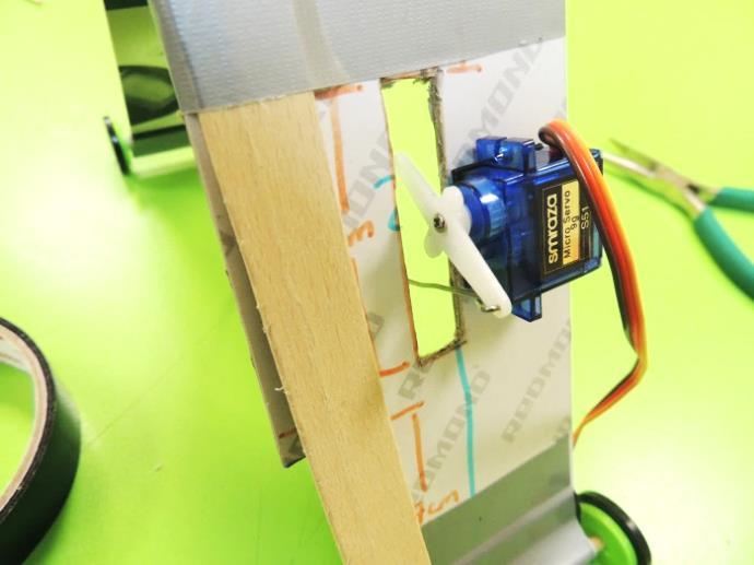
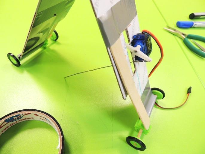
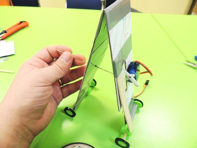
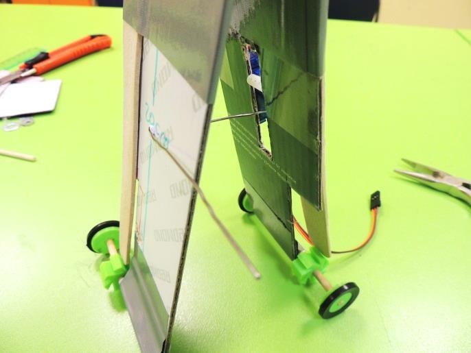
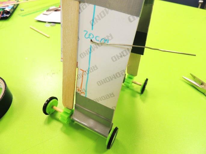
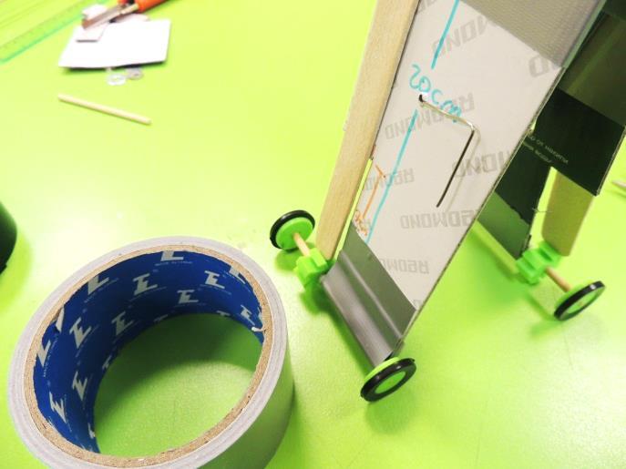
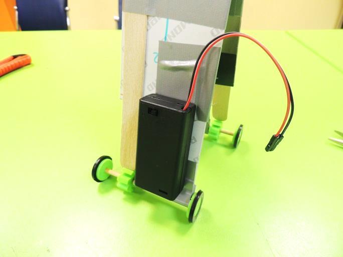
39. Take the paper clip and unbend it. Make a little hook in one end. Then, insert it in the first hole of the servo motor.
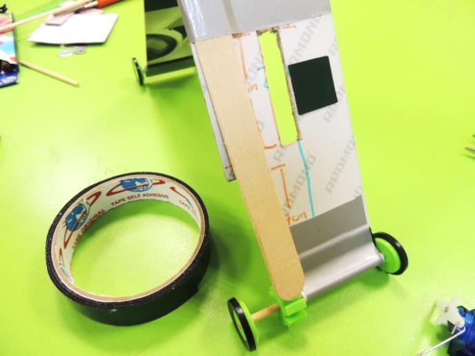
40. Attach the servo motor to the right side of the rectangular hole. Use mounting tape. The unbent clip must be inside the rectangular hole.
41. Insert the available end of the clip through the hole, and then bend it at more or less half the length of the extended clip. Then, bend it again so it has more contact surface. Stick it to the tablet using duct tape.
Connect the Micro:bit
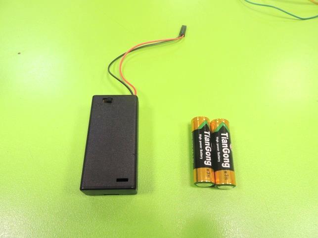
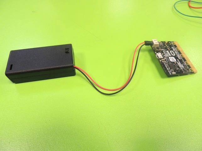
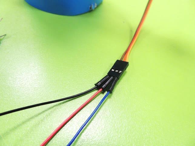
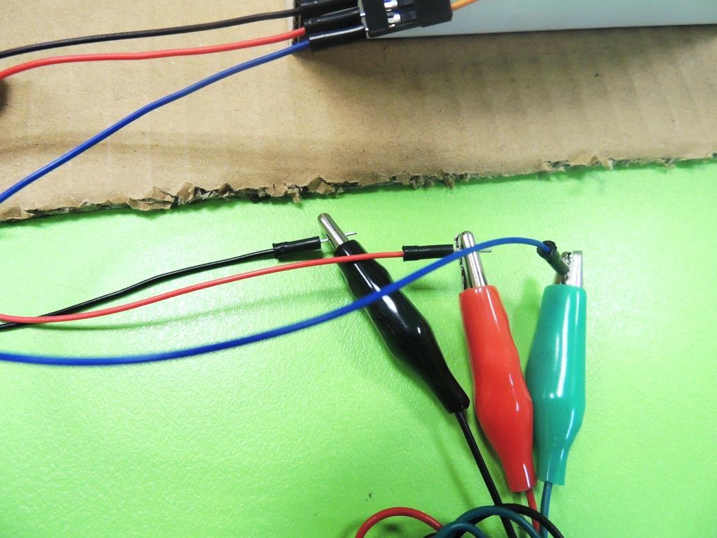
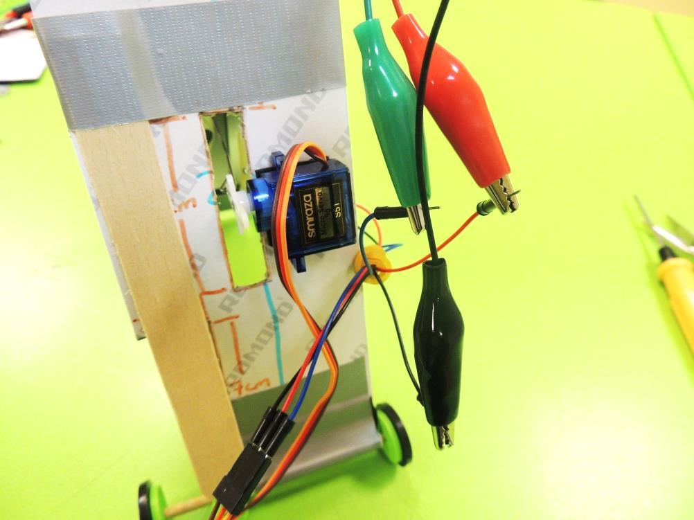
42. Insert the batteries in the battery holder and connect it to the Micro:bit.
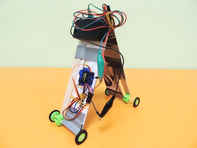
43. Now we will wire the servo motor. In its socket, insert jumper wires this way:
- Brown servo wire: black jumper wire
- Red servo wire: red jumper wire
- Orange servo wire: blue jumper wire
Now, attach alligator cables to the jumper wires, this way:
- Black jumper wire: black alligator wire
- Red jumper wire: red alligator wire
- Blue jumper wire: blue alligator wire (or green, or any other color, as long as you can differentiate it from the others.)
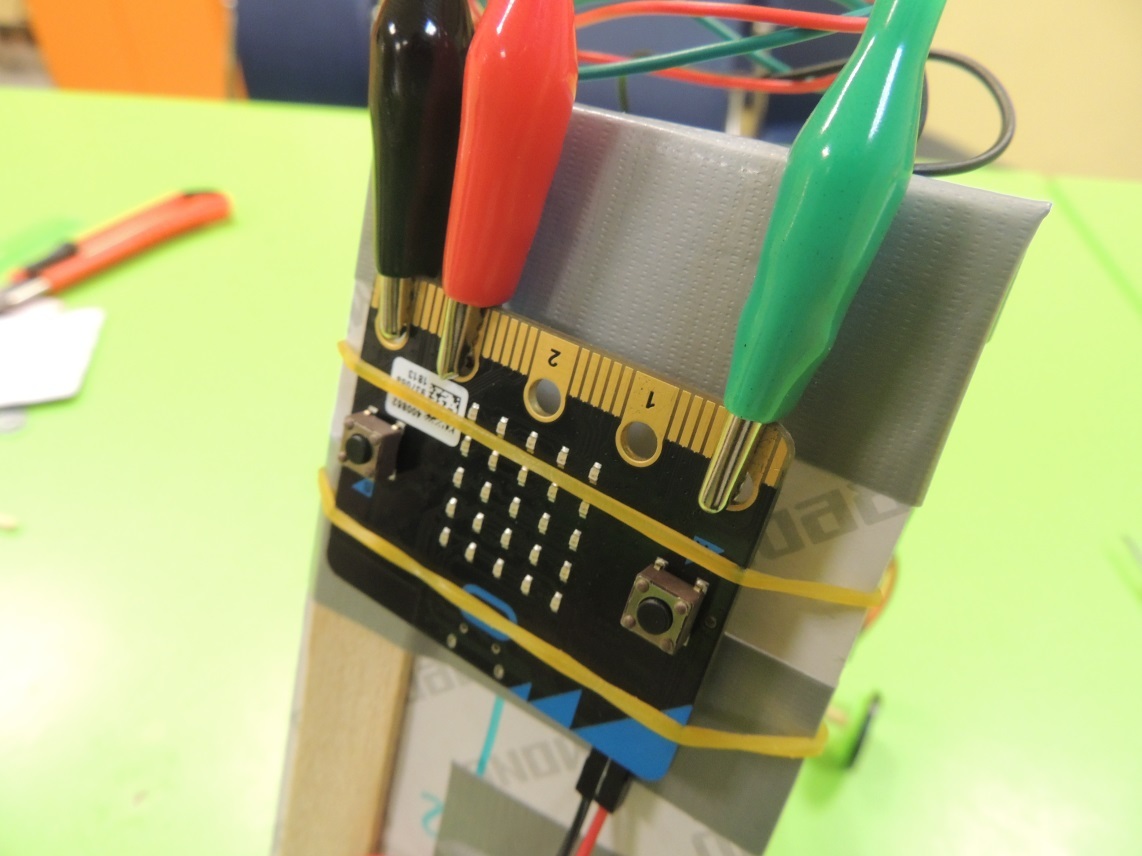
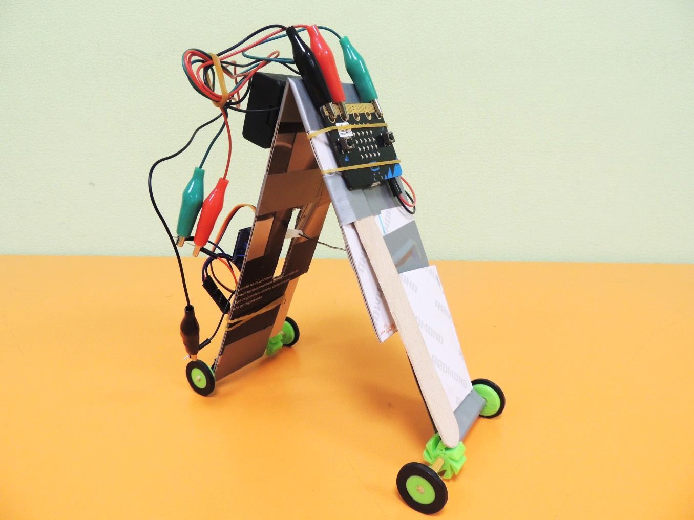
44. Now attach the Micro:bit using rubber bands, and connect the alligator cables to the pins this way:
- P0: blue alligator
- P1: Empty
- P2: Empty
- 3V: red alligator
- GND: black alligator
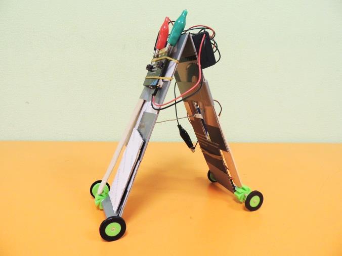
45. Stick the battery holder to the top of the center top of your robot, and test it. Probably you will have to do some troubleshooting, but that’s part of the job for an Engineer!
46. If there is time remaining, students can try an Inchworm Race, and compete to see which Inchworm arrives first to the finish line.
Third Project: Robot Arm
Introduction
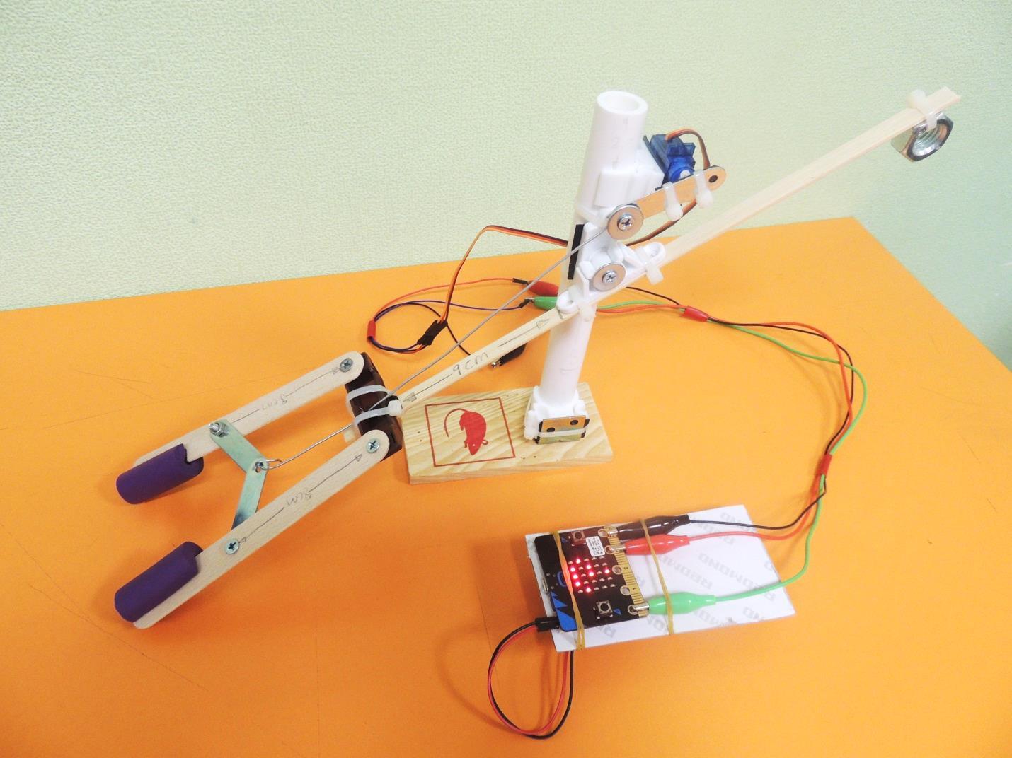
Robot arms are important technological tools in our modern world. They populate factories to create cars and airplanes, they can be used to manipulate dangerous substances without risking human lives, and they can be attached to mobile robots for space and marine exploration. In this lesson, students will apply basics of mechanical engineering to create a robot arm controlled by Micro:bit. Using only one servo, this mechanical arm will grab a plastic cup and lift it up at least 10 cm from the table.
Definitions
- Lever: simple machine consisting of a beam or rigid rod pivoted at a fixed hinge, or fulcrum.
- Counterweight: weight that, by exerting an opposite force, provides balance and stability of a mechanical system. Its purpose is to make lifting the load more efficient.
- Operator: a person who directly controls a robot’s movements.
- Servo (servo motor): component that integrates a motor, a gear box and a sensor to control the position of the shaft.
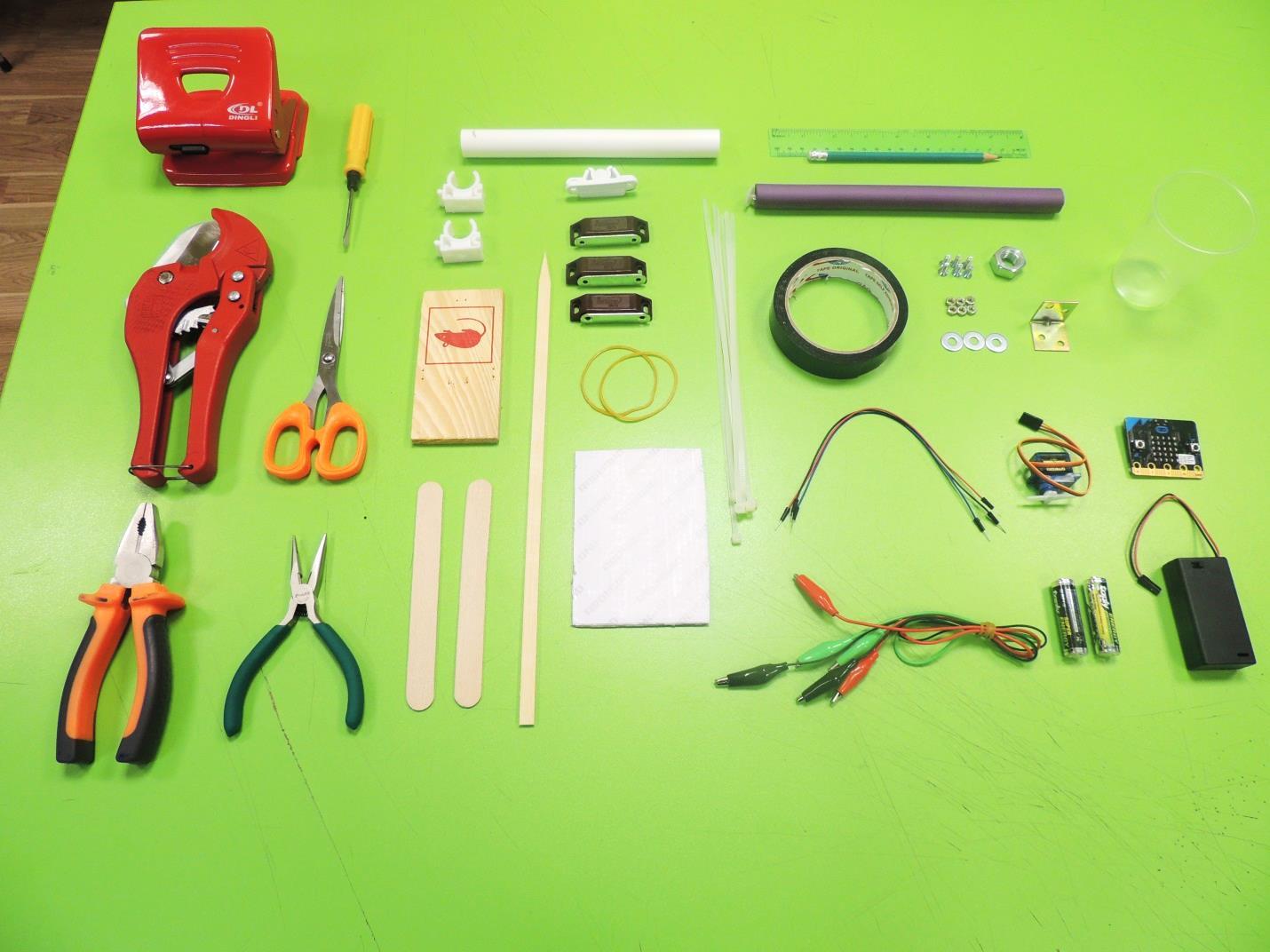
Materials per student/team (2 kids)
- 1 BBC Micro:bit board
- 1 2 AAA Batteries holder with plug for Micro:bit
- 2 AAA Batteries
- 1 USB cable for Micro:bit
- 1 Servomotor with double-arm horn and screw
- 3 Alligator Test Leads (red, black and blue)
- 3 Jumper wires (red, black and blue)
- 1 Mounting Tape (double-sided scotch, thick, black)
- 10 zip ties 3 rubber bands
- 1 flat kebab stick
- 2 craft sticks
- 3 sets of magnets for cabinets
- 1 set of plastic lock for cabinet (two pieces)
- 1 foam hair roller
- 1 wood tablet of 12cm x 6cm x 1cm (a mousetrap of those dimensions with all metal parts removed may work)
- 1 cardboard sheet (12cm x 6cm approx.)
- 1 PVC pipe (2cm diameter x 20cm length)
- 2 PVC holders for PVC pipe 1 hex nut (12 mm of inner diameter)
- 1 Metal angle
- 6 M4 x 10 bolts
- 6 M4 nuts
- 4 metal washers
- 1 ruler
- 1 pencil
- 1 pair of scissors
- 1 pliers
- 1 needle nose pliers
- 1 PVC cutter
- 1 hole puncher
- 1 screwdriver
- 1 set of color markers
- 1 plastic cup
- 1 Computer with internet access or Makecode offline editor installed.
- OPTIONAL: Copper wire of 25 cm x 1.3 mm diameter. 1 hot glue gun per classroom.
Warnings About Materials and Pre-lesson
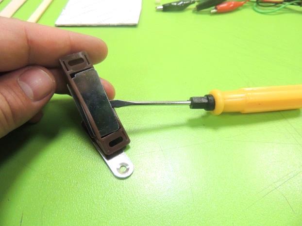
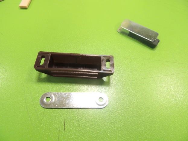
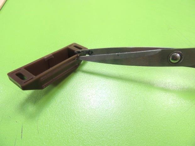
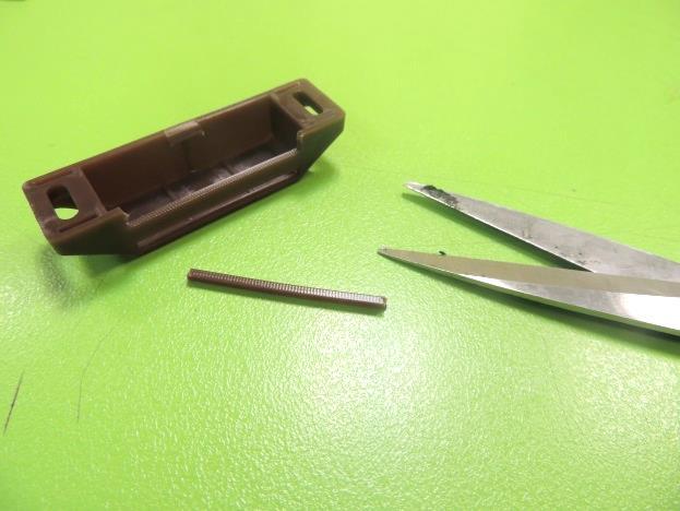
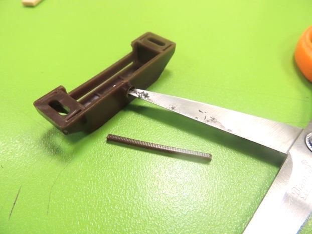
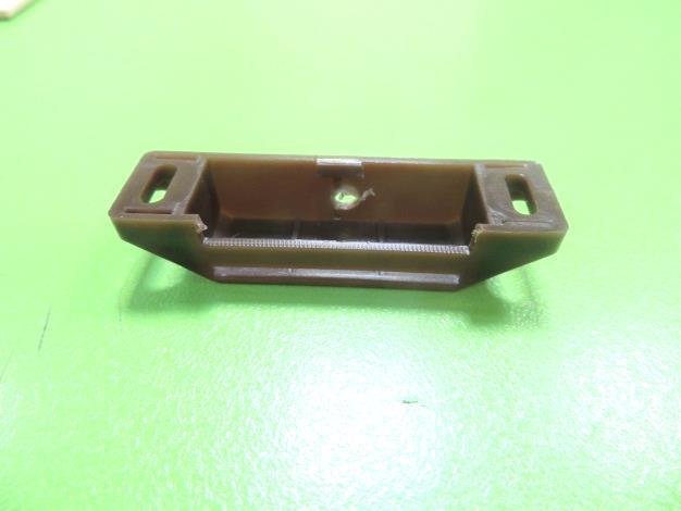
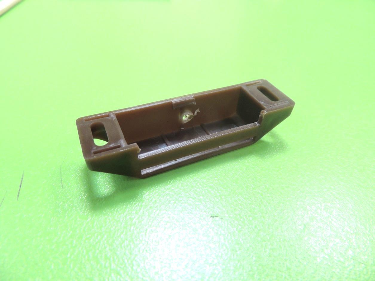
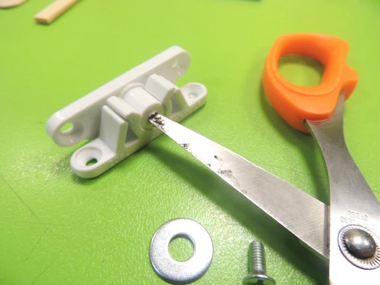
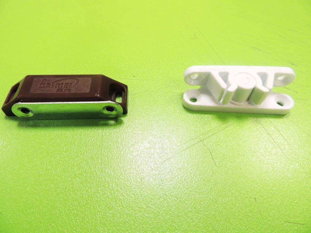
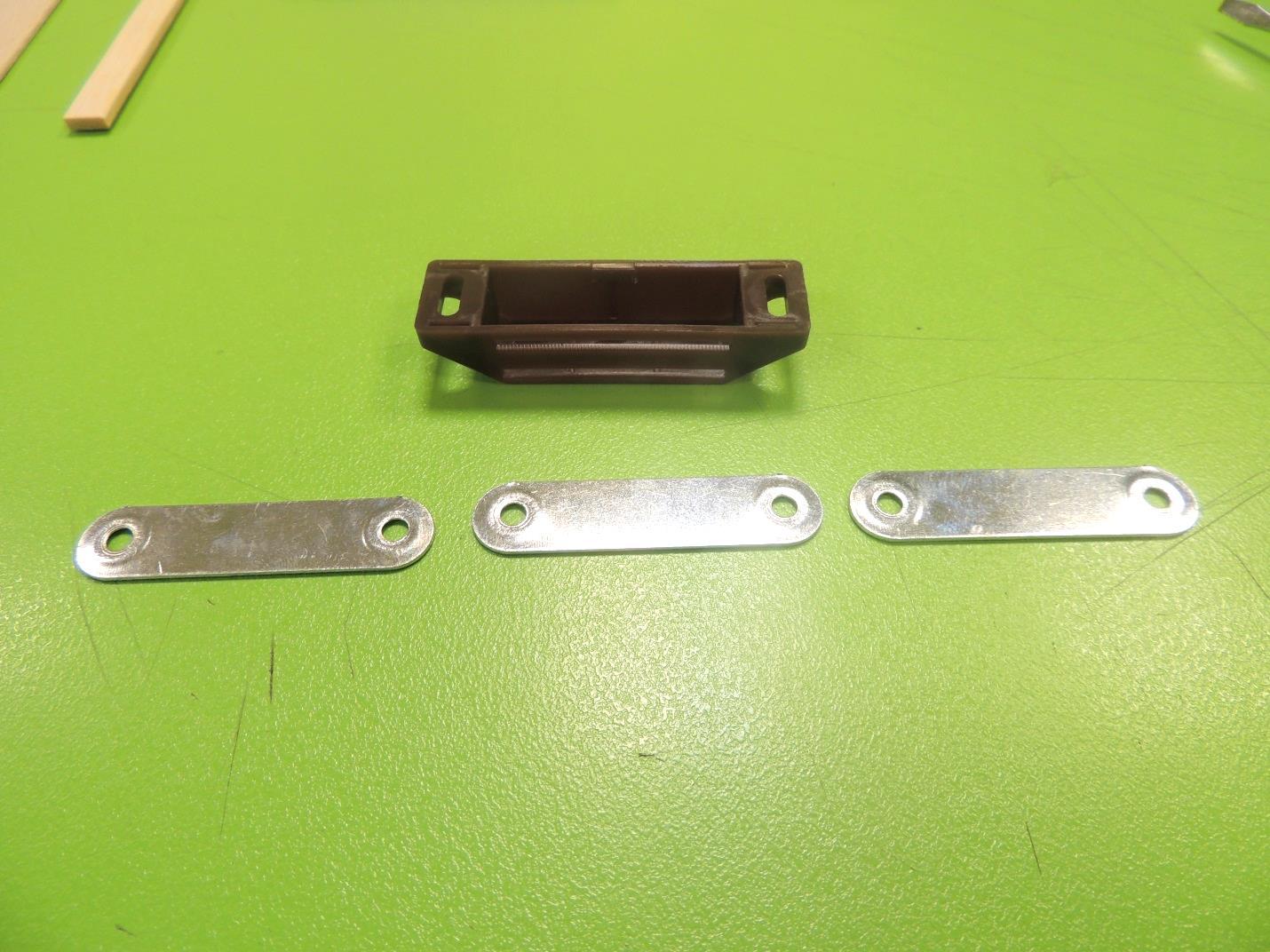
We will need to types of sets for cabinet: magnetic (a magnet in the cabinet attracts a metal piece in the door) and plastic (a plastic piece in the cabinet fits inside a plastic piece in the door)
From the 3 magnetic locks we will need only 1 plastic cover and the three metal brackets with a hole on each end. This will look like a waste, but probable you already have several of those pieces from the “Smart Garage” lesson, and you can keep the remaining parts for future STEAM activities.
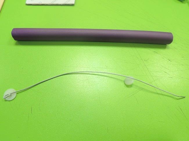
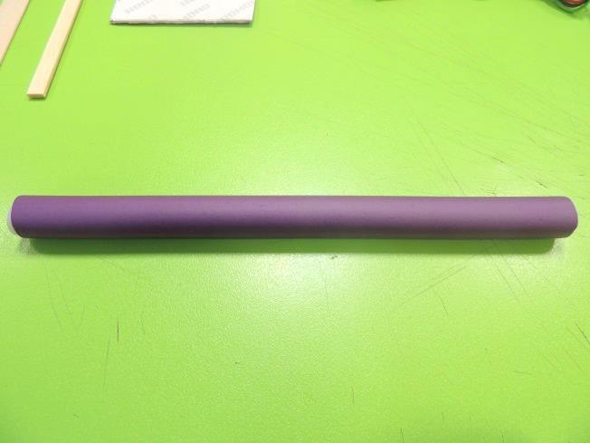
About the foamy hair rollers, they are great materials for several STEAM activities, and you can find inside them the wire required for this robot arm. However, be warned that sometimes this wire comes rusty and is not suitable for the project, so better have a roll of copper wire of 1.3 mm as a contingency plan.
Pre-lesson
- Disassemble one of the cabinet magnets (don’t forget the keep the metal bracket) and modify the plastic case. Using pointy scissors, cut the first plastic strip and open a hole on the opposite side.
- Now take the plastic set for cabinet and open a small hole in the center of the cylinder. Be careful, for the hole’s diameter must be just big enough to allow a M4 bolt to be screwed in a tight way. Too loose, and the bolt will not have a proper attachment.
- Make bags with the materials to distribute later to each kid. 4. Verify that your classroom has access to internet. If not, download and install the offline Makecode app on each computer (https://makecode.microbit.org/offline-app)
- Make a prototype of this project, so you can show it to the students.
Micro:bit Code
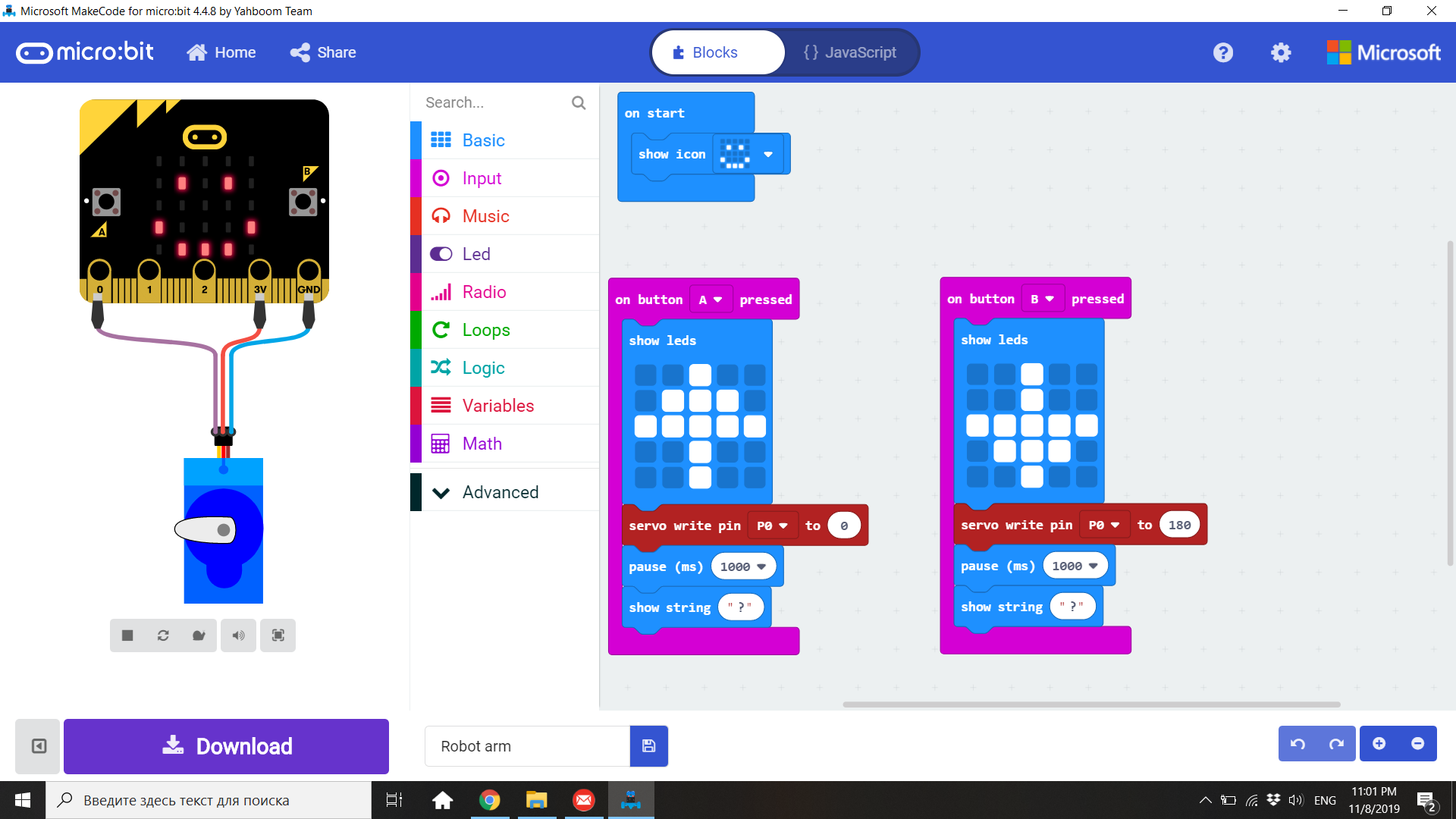
1. This lesson will be divided into two sections: a coding one and a hardware one. First, kids will create and download the code. Then they will create the physical part of the robot arm.
2. Students must open Makecode and click in “New Project”; then click in the world “untitled” and rename it “Robot Arm”. 3. This is the code for the lesson. In consideration that this project will demand a lot of work in the mechanical part, the Micro:bit will basically activate the servo and lift the arm up when button A is pressed, and lower the arm when the button B is pressed. The servomotor will be connected to the pins 3V and GND to power it, and to pin 0 to control it. When you finish, download the program to the Micro:bit.
Fingers
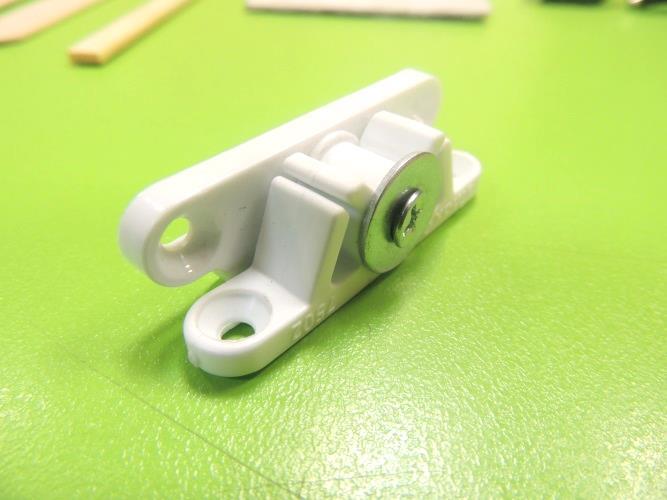
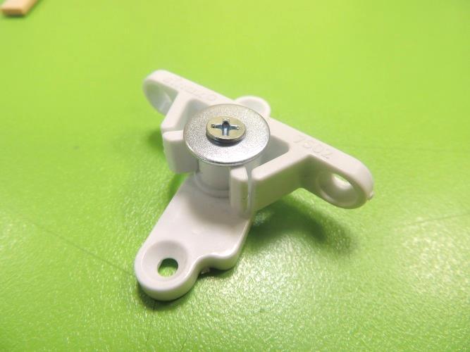
4. Now let’s start building the arm. Take the plastic lock for cabinet. Insert a washer into one of the bolts and now screw the bolt into the hole of the plastic lock, using a screwdriver.
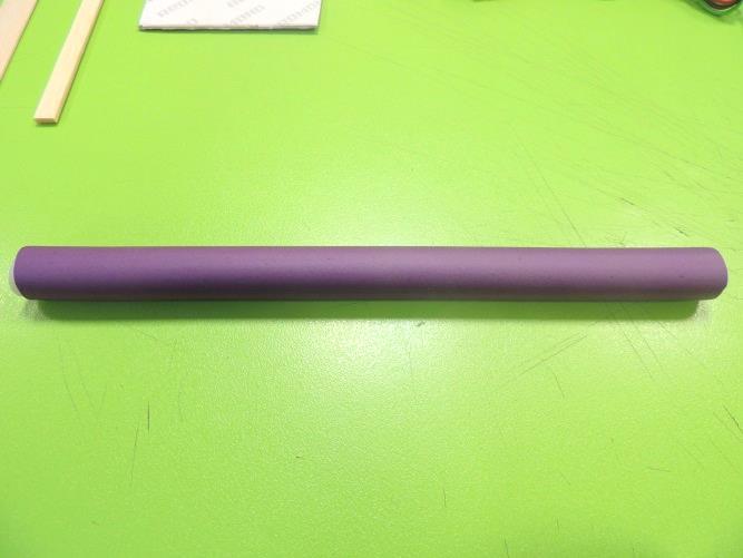
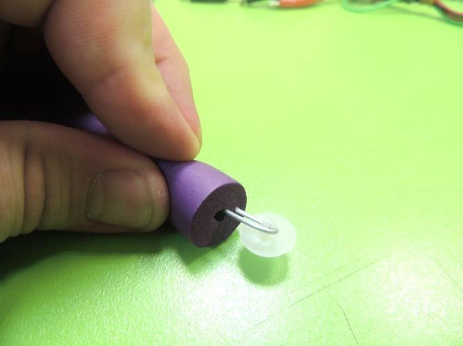
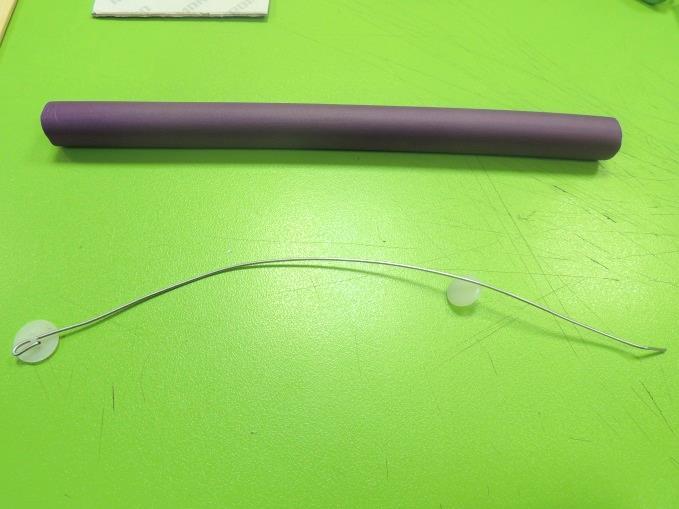
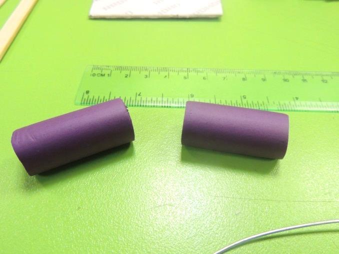
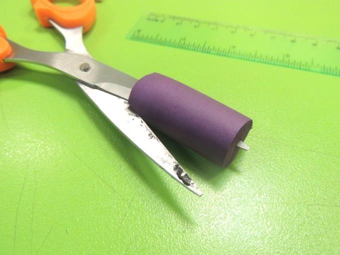
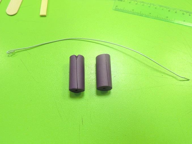
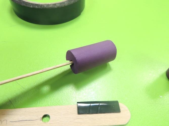
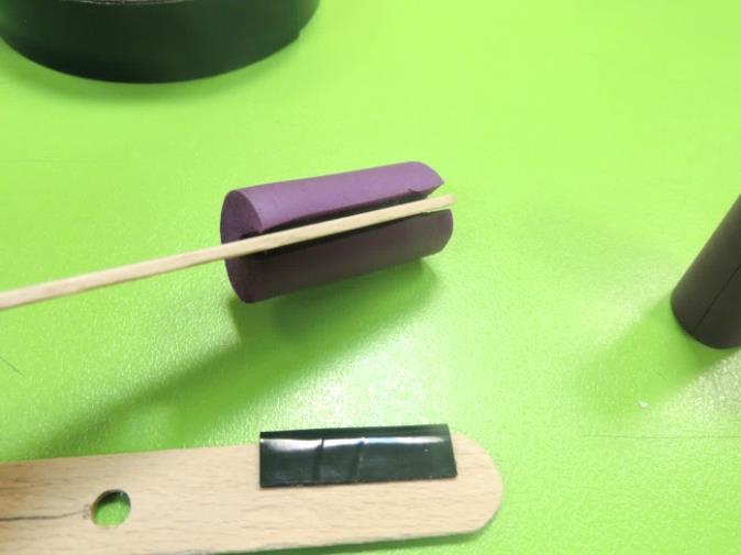
5. Take the hair roller, extract the wire (be careful of not breaking or over bend it! We will need it for this project). After that, cut 2 segments of foam of 4cm each, and make a cut along it, using scissors. The cut must be from the outer side to the center, not completely along the diameter.
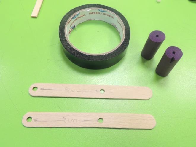
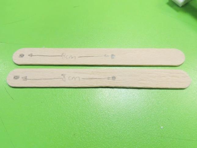
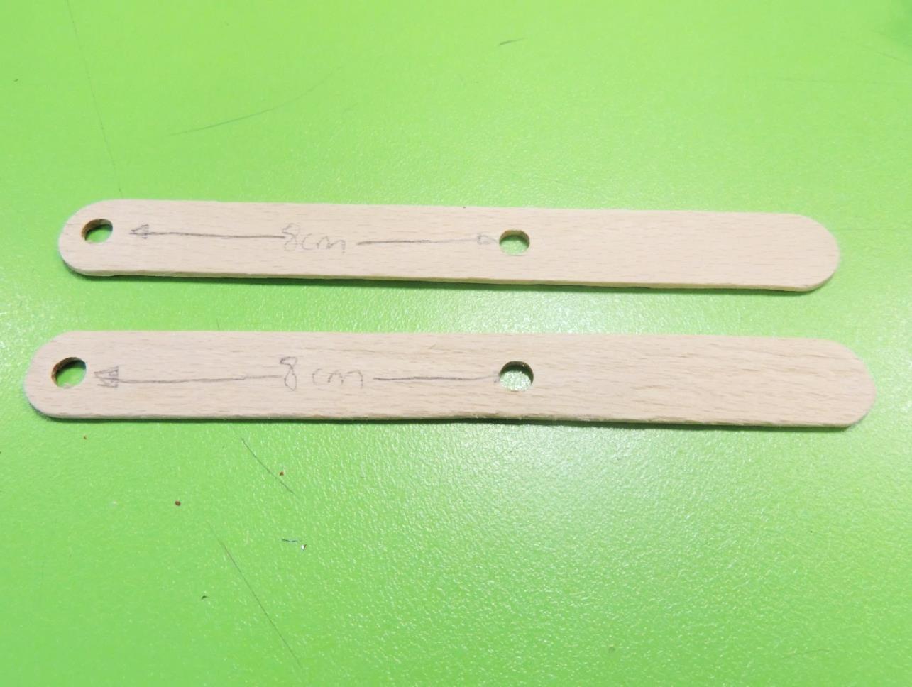
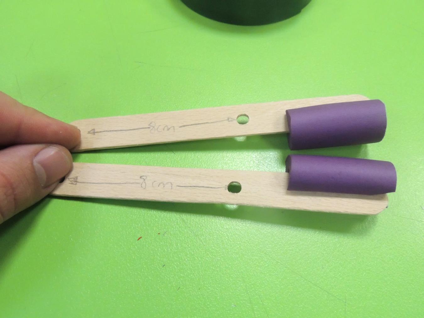
6. Take both craft stick and mark a spot in one of the ends. Then mark another one 8 cm away. Using the hole puncher, make a hole in these spots.
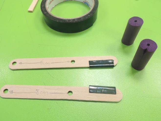
7. Stick a piece of mounting tape at one side of the available end of each craft stick. Then stick the foam segments on each one. They will work as “fingers”.
Claw
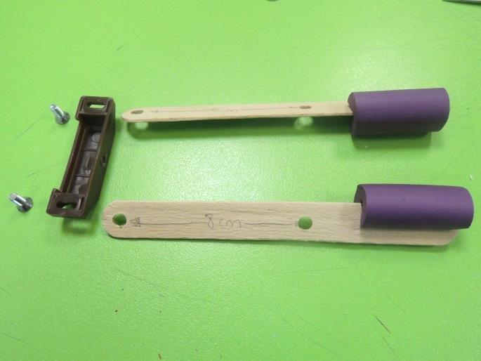
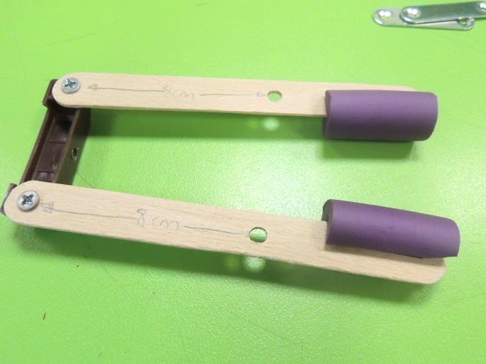
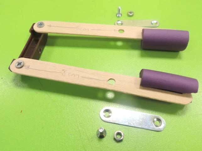
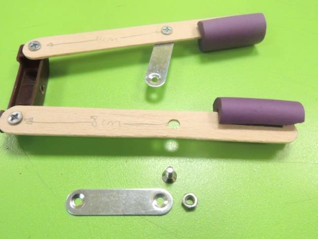
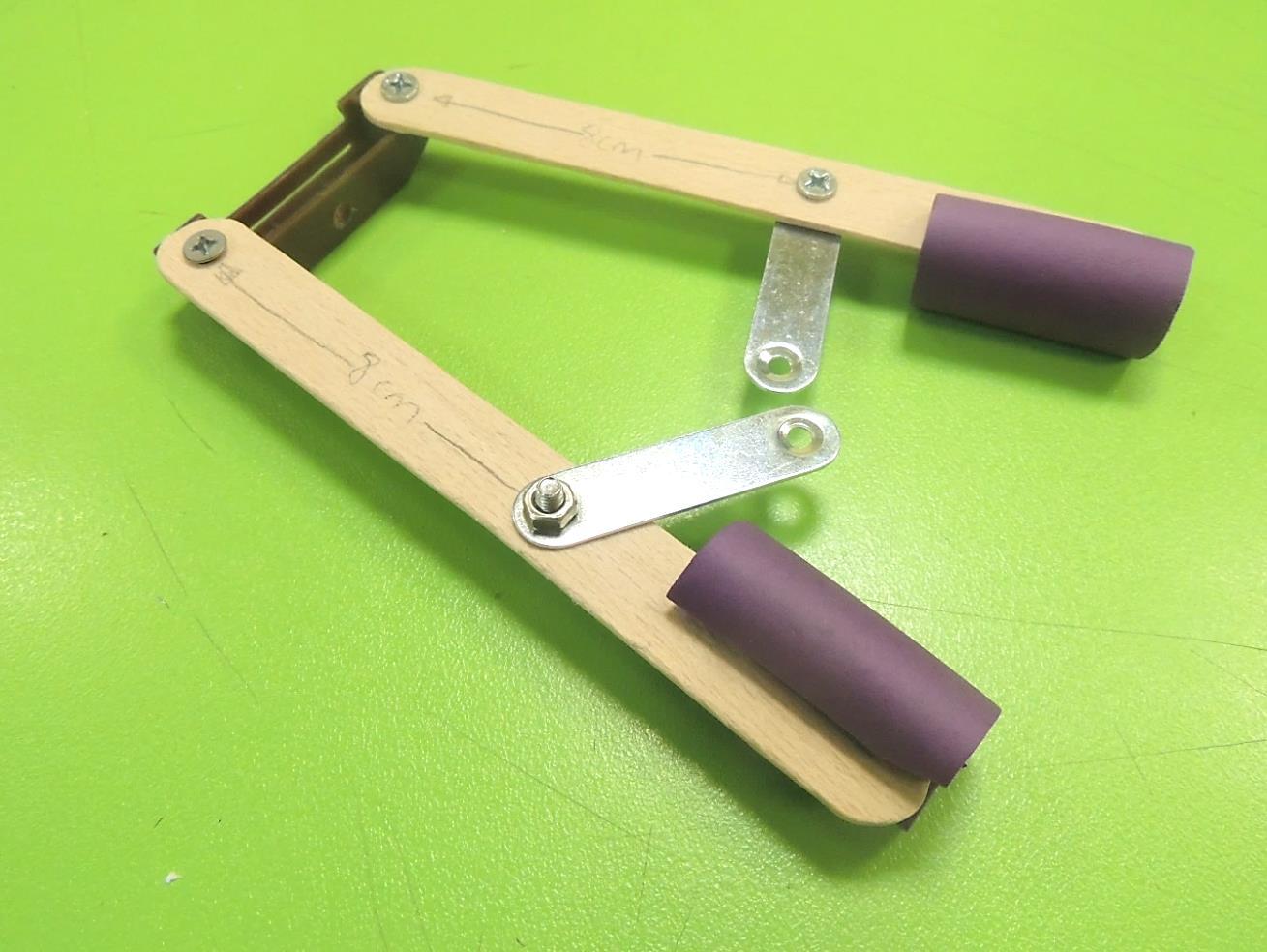
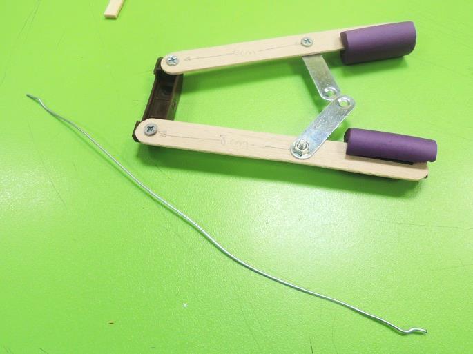
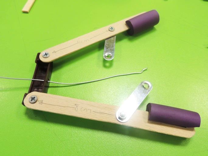
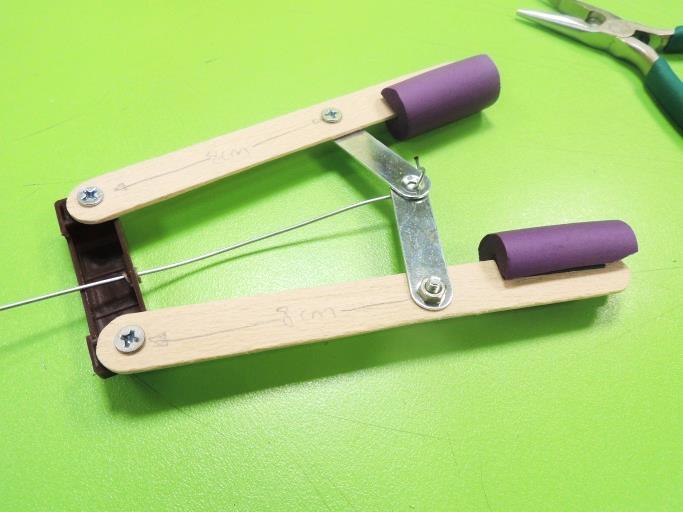
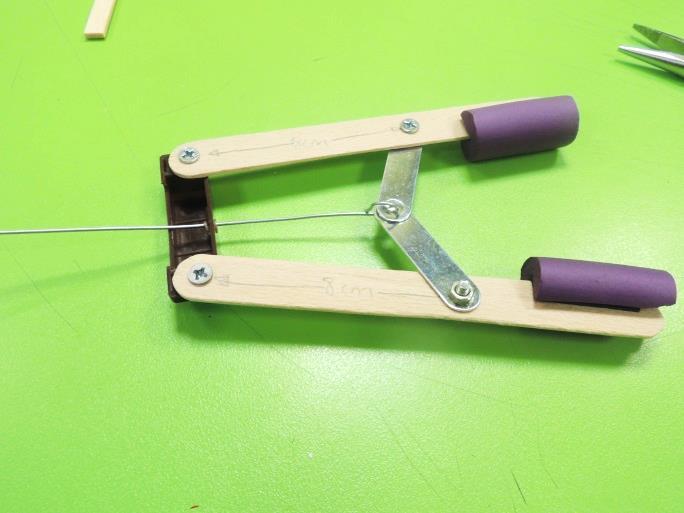
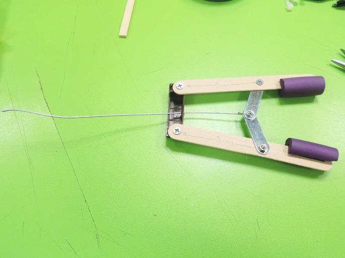
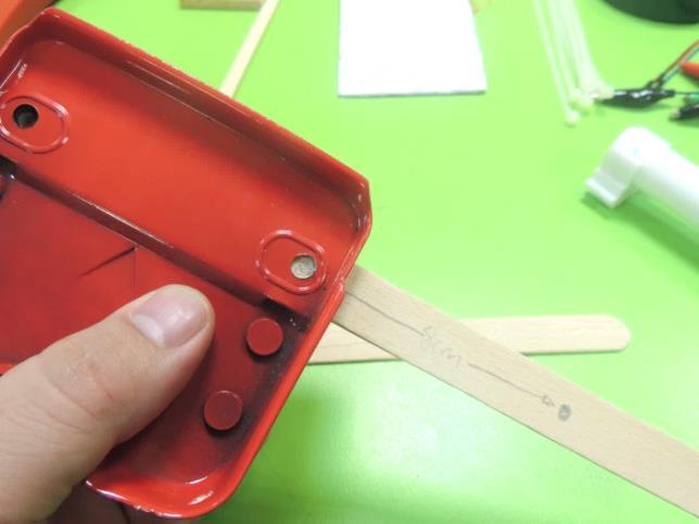
8. Bring the modified plastic case from the cabinet magnet. Attach the craft sticks to it, screwing a bolt through the first hole of each craft stick to the holes of the plastic piece. Don’t screw it too tight.
9. On the middle hole of each craft stick, attach a metal bracket passing a bolt through the holes of the stick and the bracket. Fasten it with a nut.
10. Bring the hair roller’s wire and pass it through the hole of the plastic case. Make a hoot at the end, using the needle nose pliers, and pass it through the available holes of the metal brackets. Then close the hook, and verify that the pincers open and close when you pull or push the wire.
Arm and Counterweight
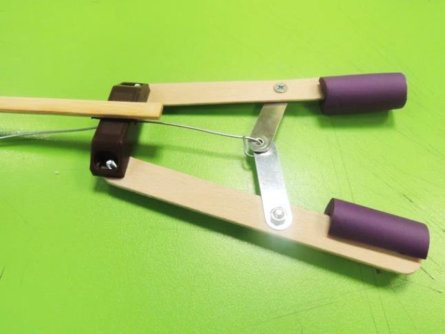
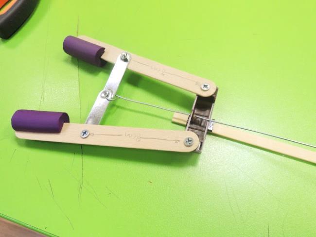
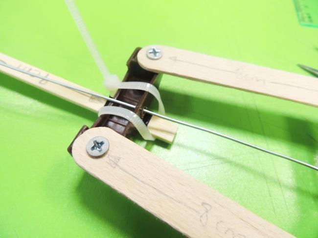
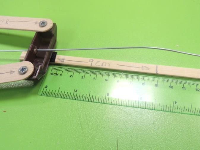
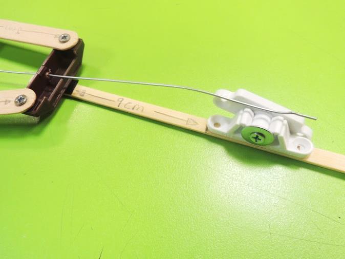
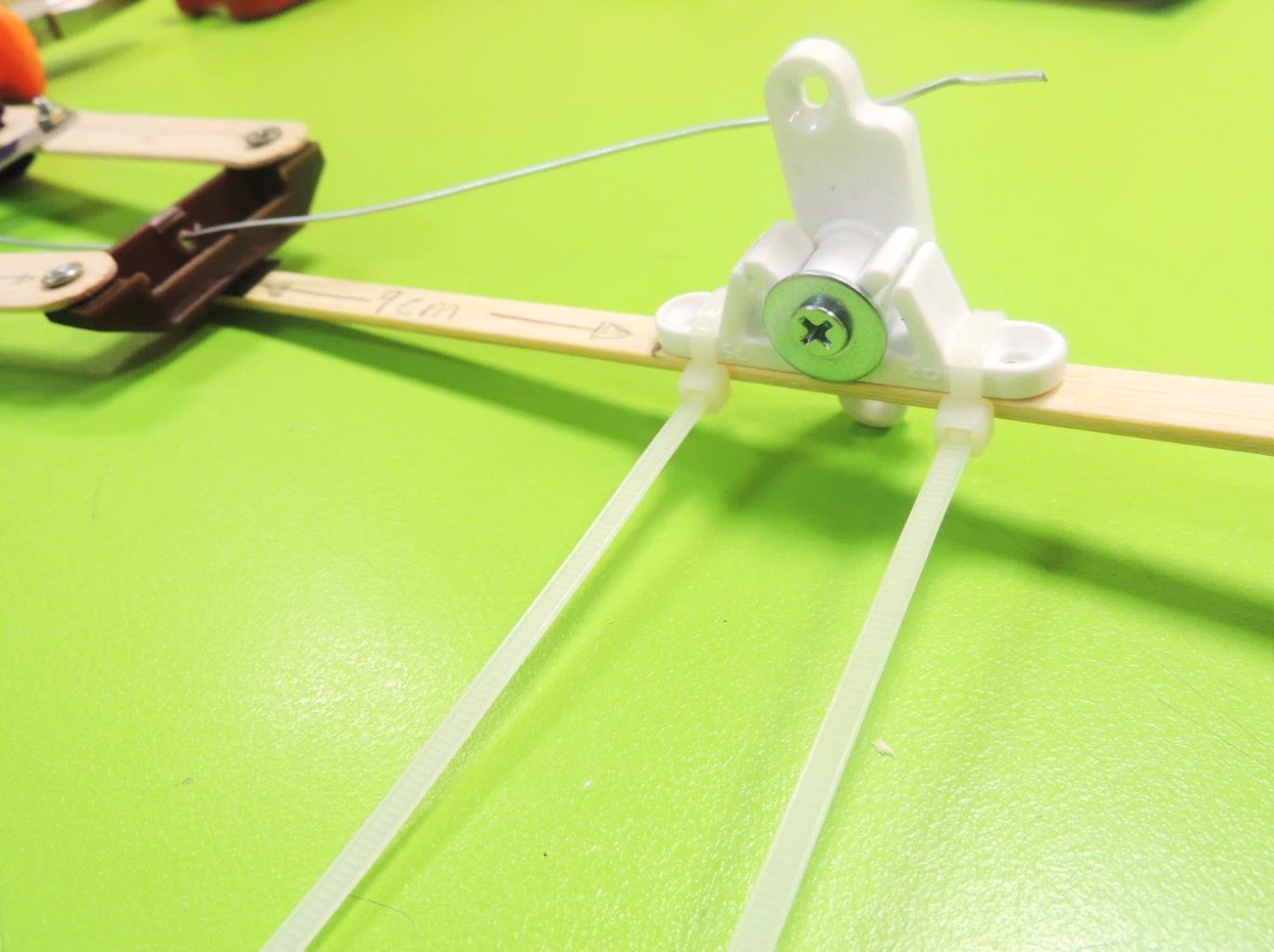
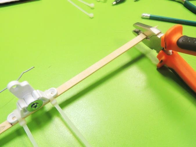
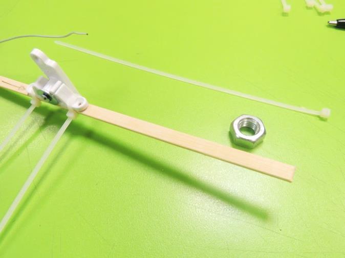
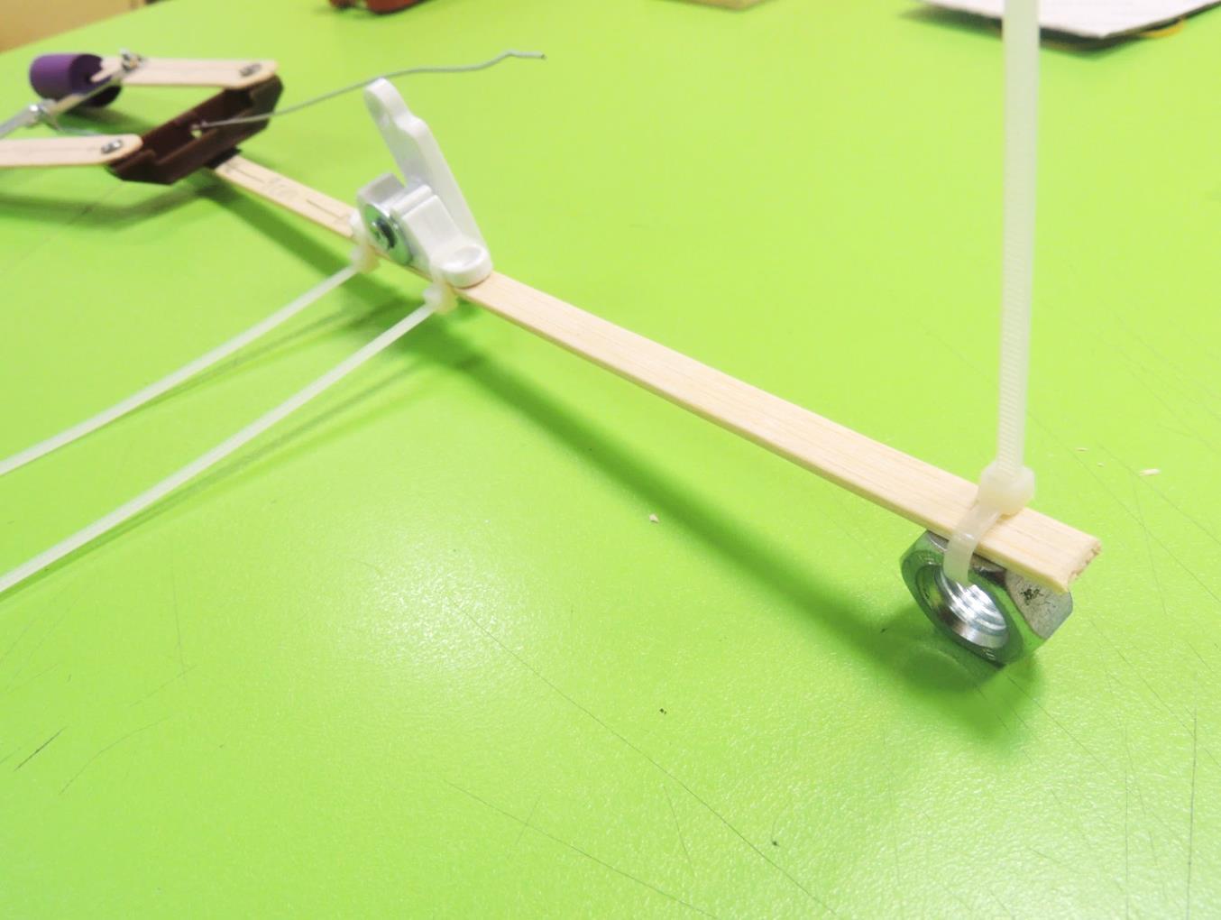
11. Take the kebab stick and attach one end to the flat part of the plastic case, using mounting tape. You can reinforce the attachment using a zip tie.
12. Over the kebab stick, mark a distance of 9 cm from the pincer’s plastic case. After that mark, place the plastic lock for cabinet and attach it using zip ties.
13. On the opposite end of the kebab stick, attach the hex nut using a zip tie. This will be the counterweight.
Base
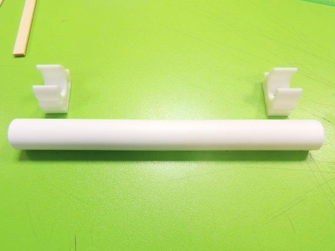
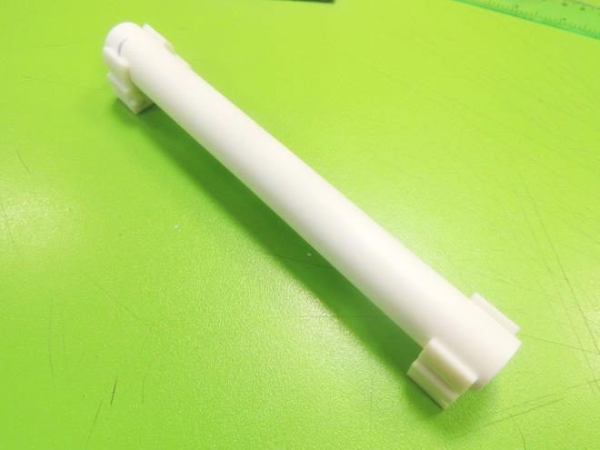
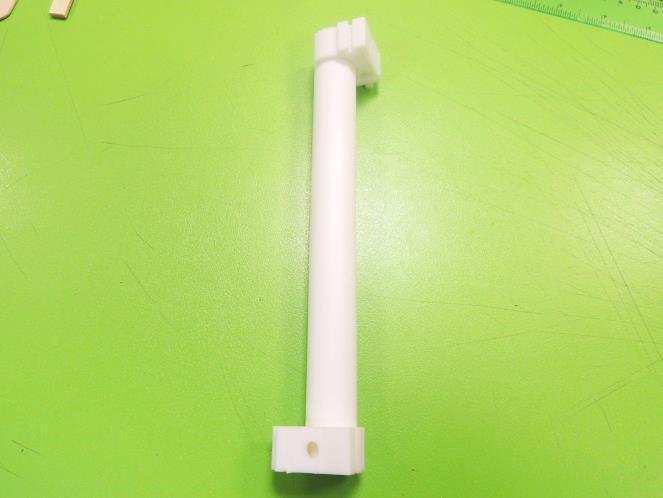
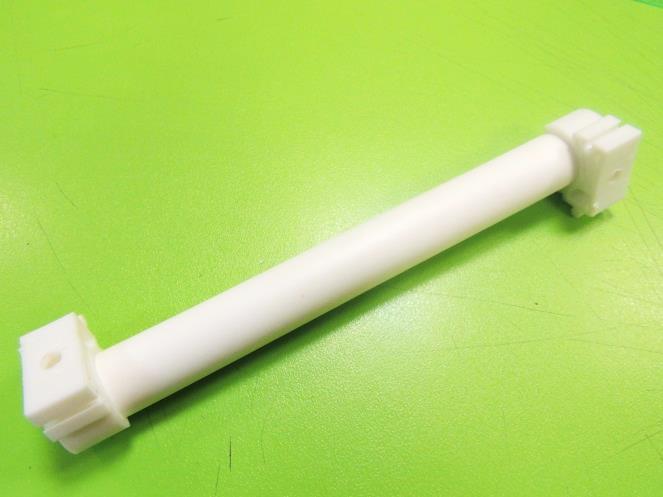
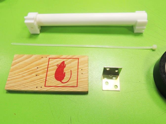
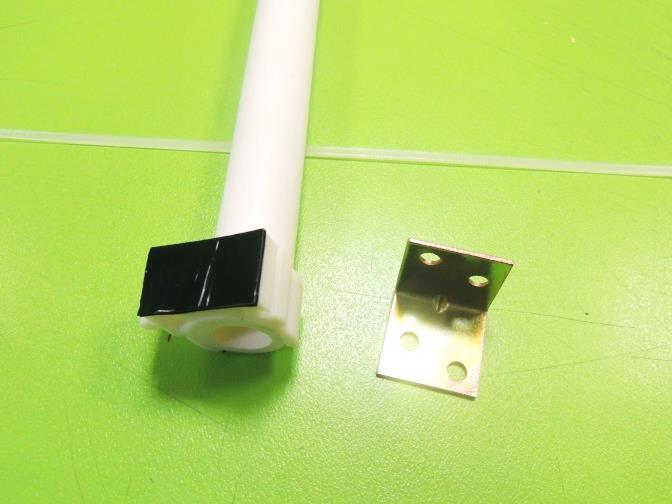
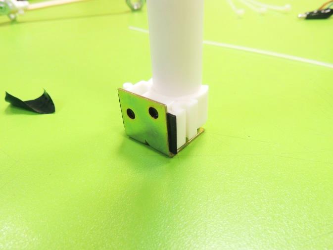
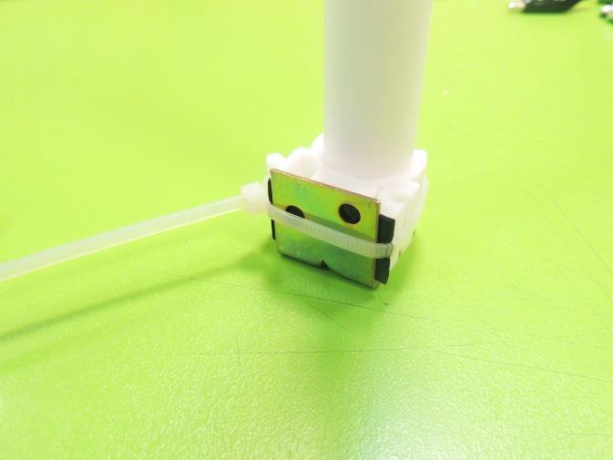
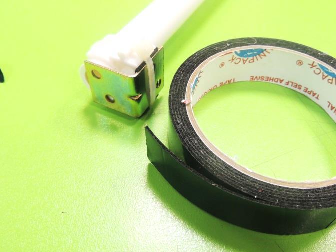
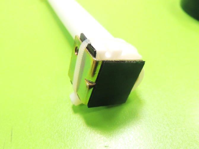
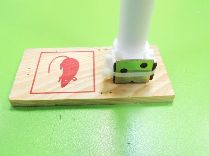
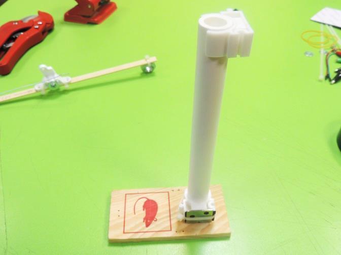
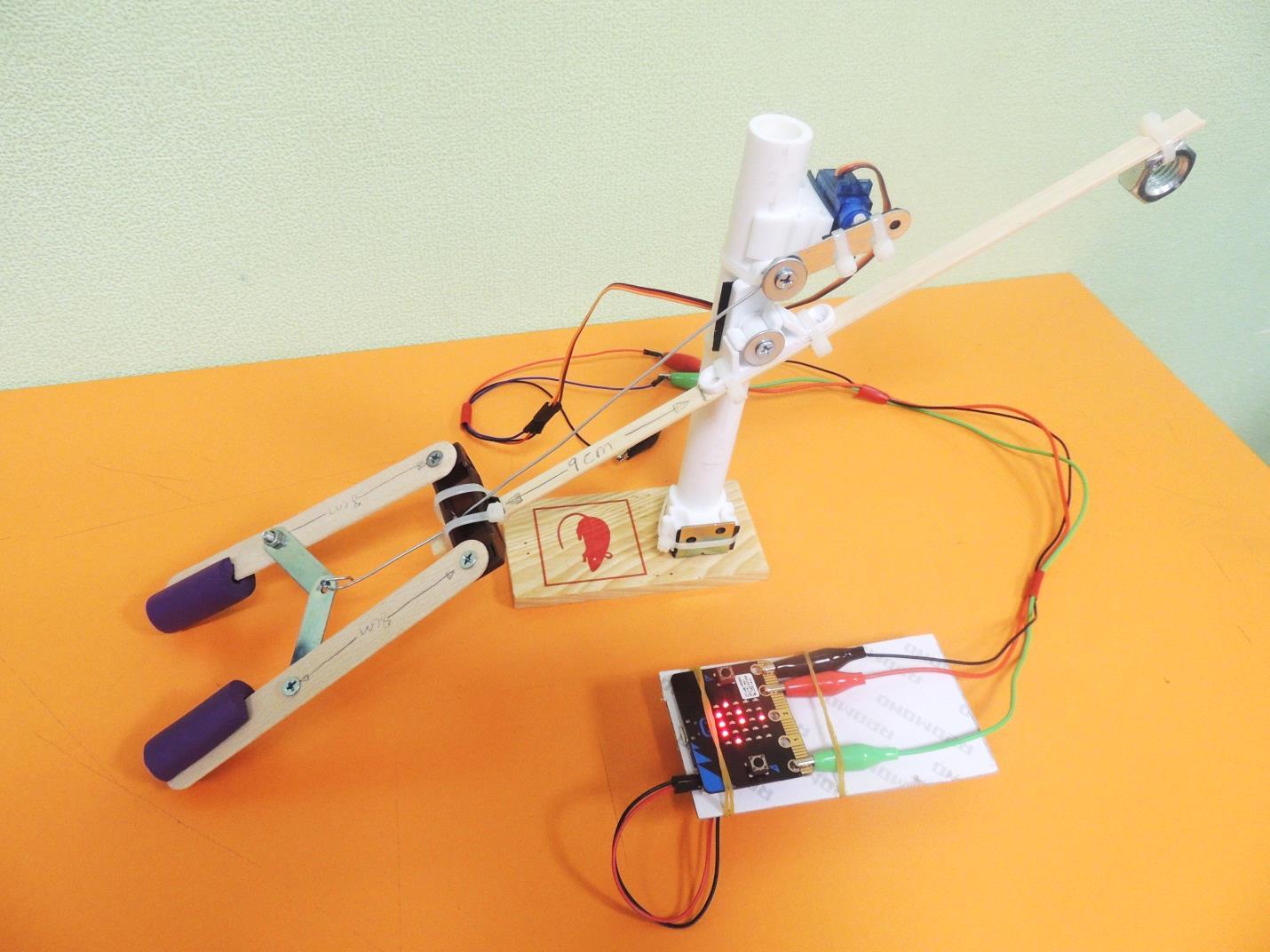
14. Now we will start working on the base. Take the PVC pipe and attach the PVC holders in the way shown on the picture.
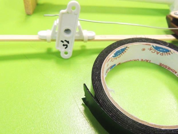
15. Using the mounting tape, stick the metal angle to the PVC holder and fasten with a zip tie. Then stick the available part of the metal angle to the woof piece, to create a stand for the mechanical arm.
Attaching the Arm to the Base
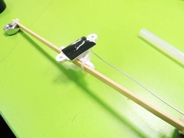
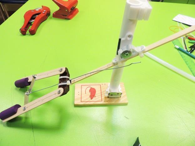
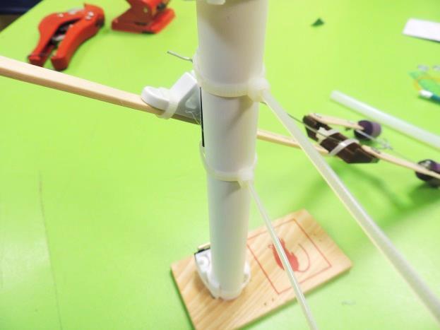
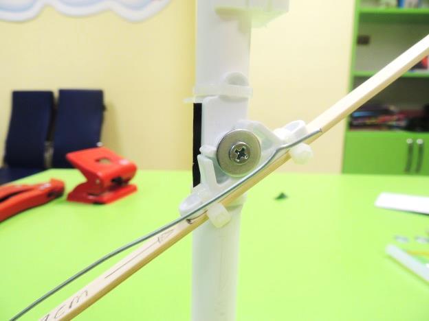
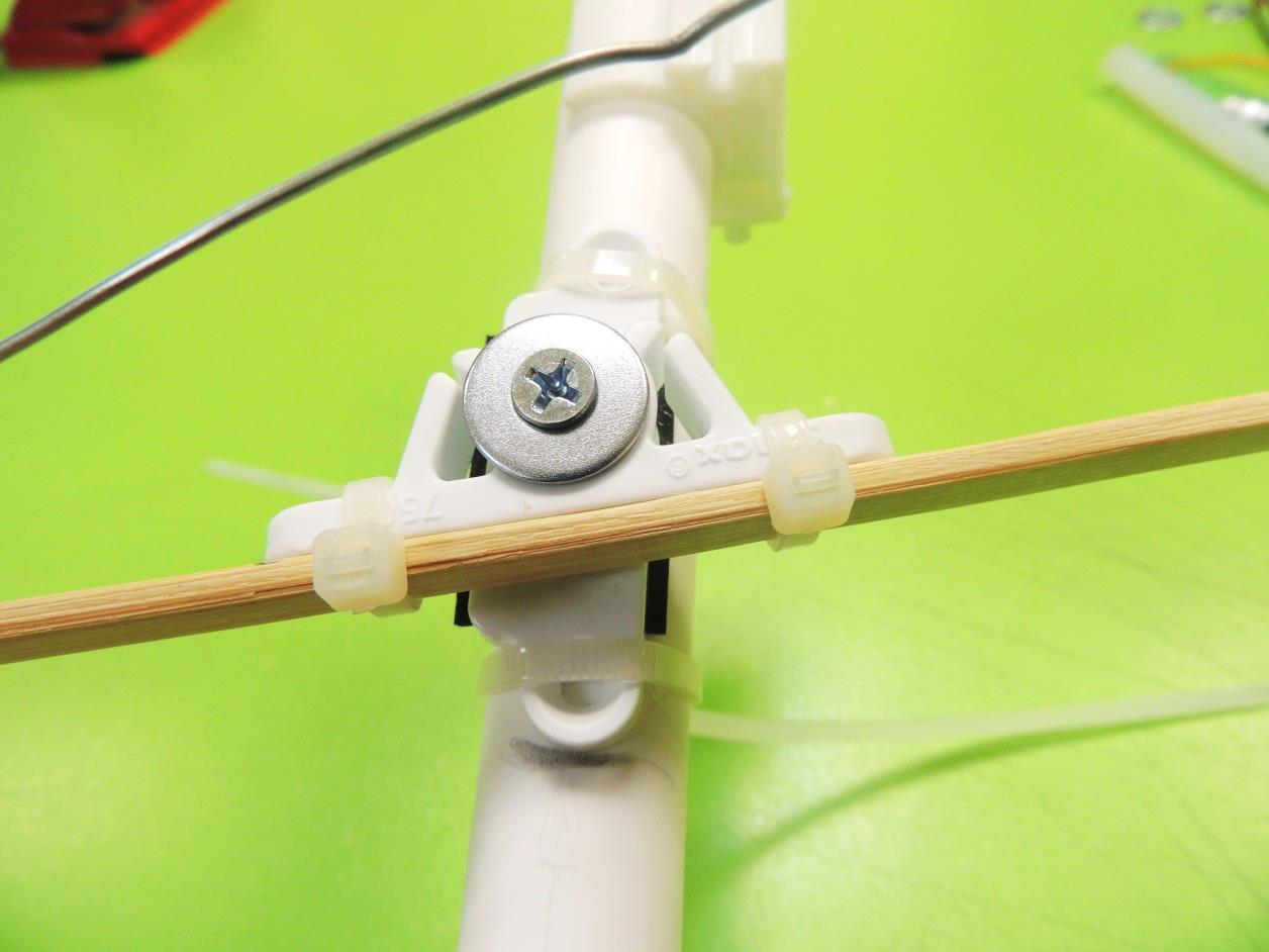
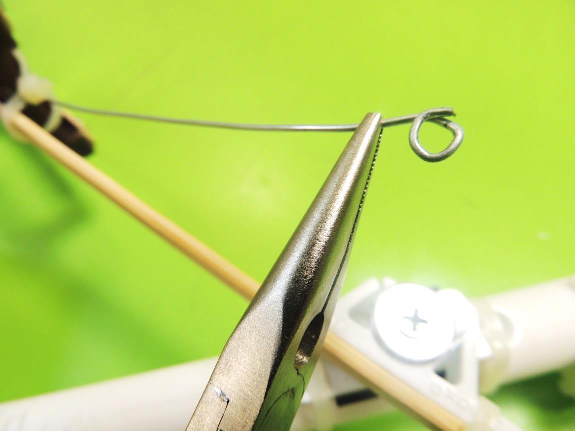
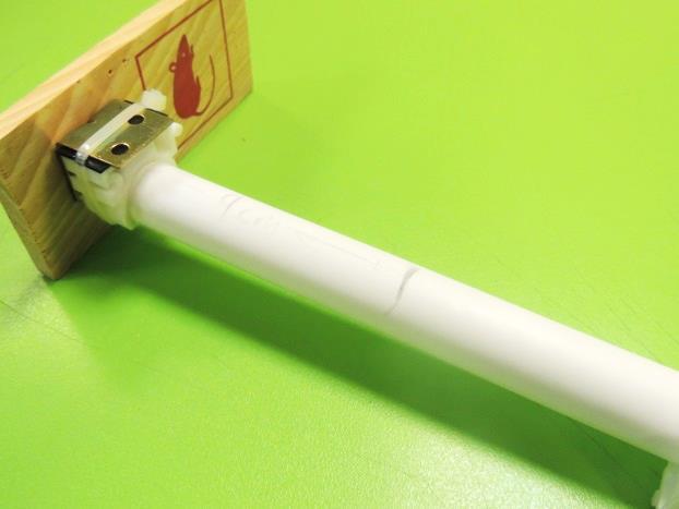
16. Over the PVC pipe, mark a distance of 9 cm from the base. Place a piece of mounting tape on the available side of the plastic cabinet lock, and stick it to the PVC pipe after the mark. Fasten the plastic lock to the pipe using zip ties.
17. Take the available end of the wire, and make a loop using the needle nose pliers.
Servo
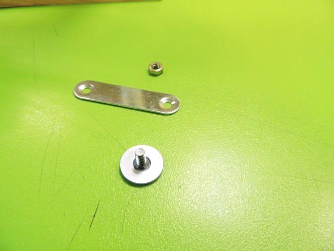
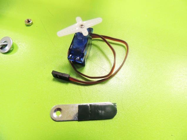
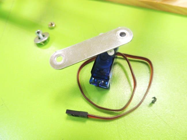
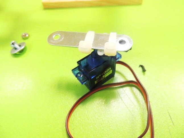
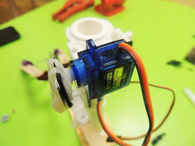
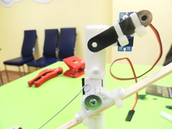
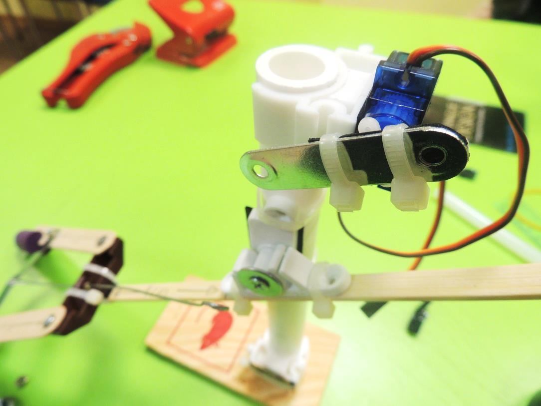
18. Stick a piece of mounting tape on a metal bracket, leaving one available hole. Then attach the bracket to the arms of the servo, and fasten with zip ties.
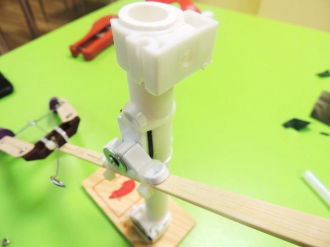
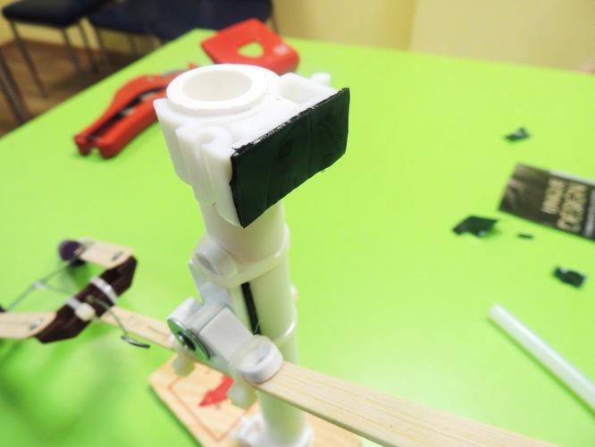
19. Stick a piece of mounting tape on the flat side of the PVC holder at the top, and stick the servo on it (side without sticker). Also, check that the servo arm can rotate clockwise from the 8:00 position to the 2:00 position.
Connecting the Arm to the Servo
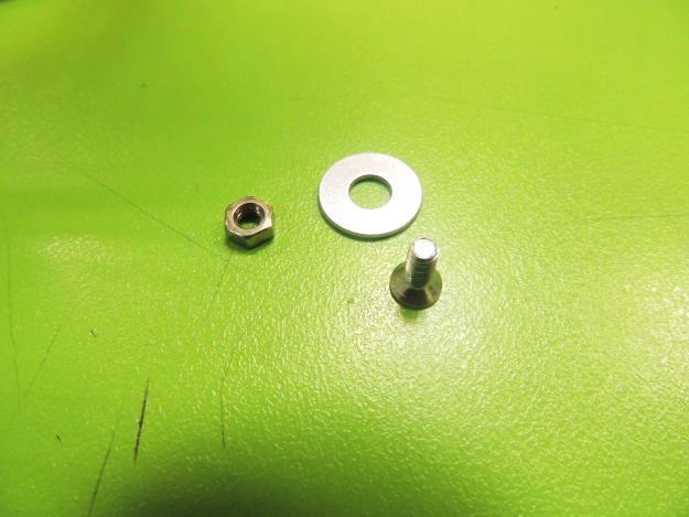
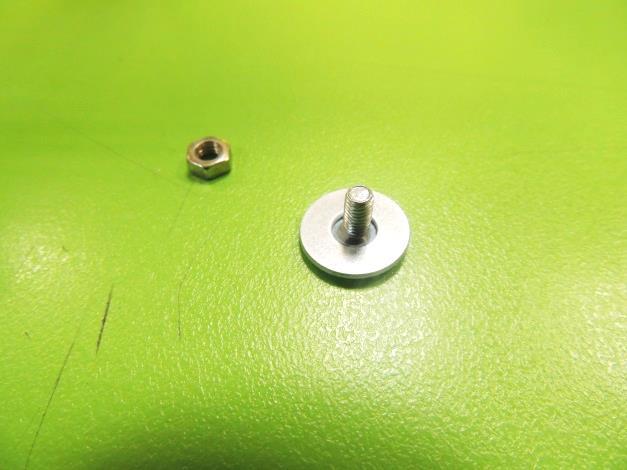
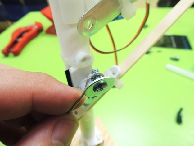
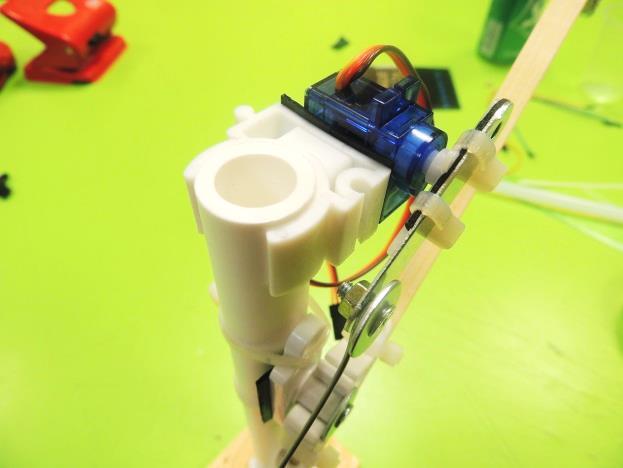
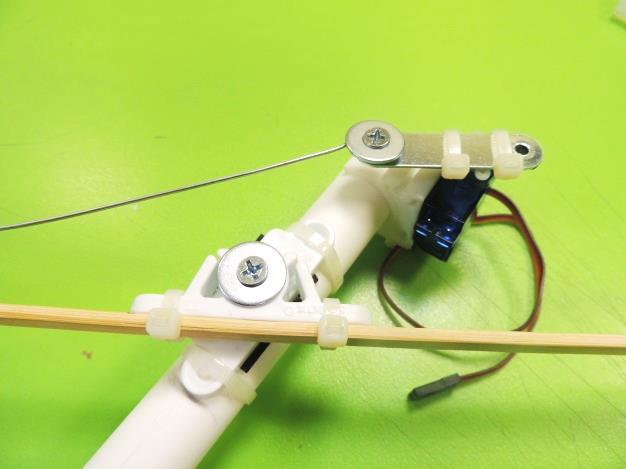
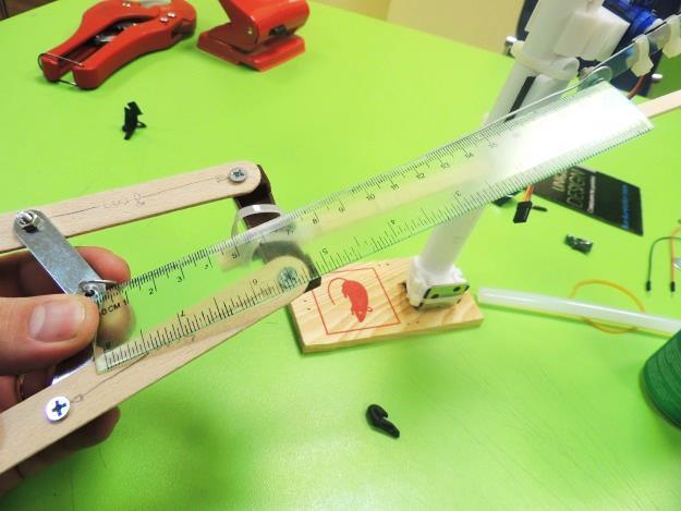
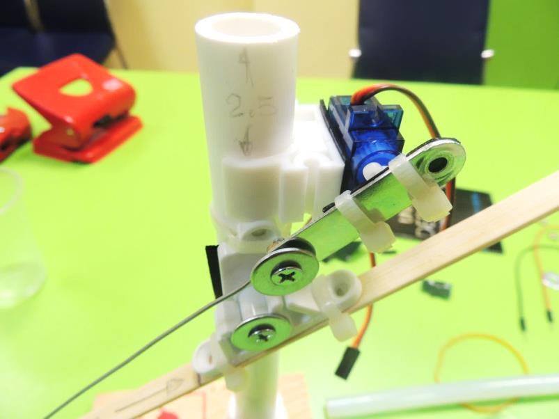
20. Now, using a bolt, a nut and a washer, attach the wire’s loop to the servo’s bracket. There must be more or less 20 cm of wire between the hook in the pincers and the loop in the servo. Mechanically test that, when you rotate the servo’s arm, the arm will react first closing the grip, and second, rising the arm. If it doesn’t work, make some adjustments. In this example, it was necessary to lower the servo 2.5 cm. Also, maybe it will be necessary to shorten the wire a little bit, or sliding the arm (kebab stick) to change the position related to the fulcrum. It depends of your construction.
Wiring the Micro:bit: Remote Control
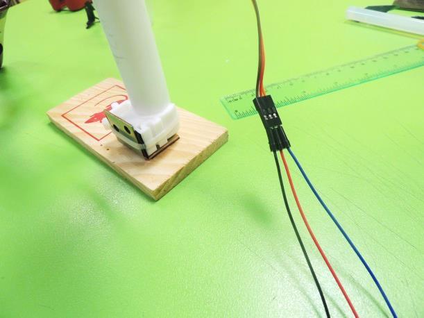
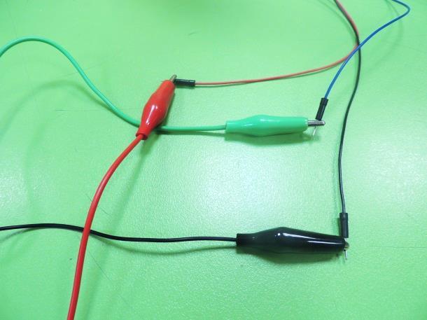
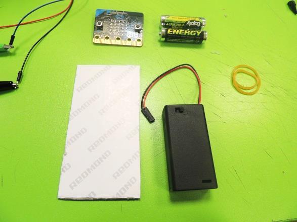
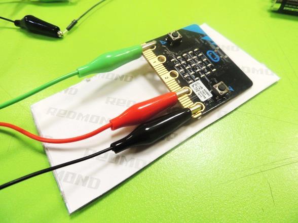
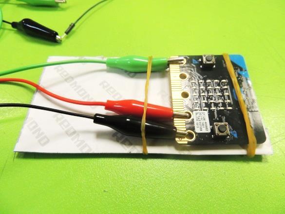
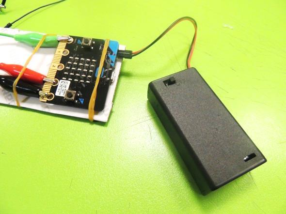
21. Now we will wire the servo motor. In its socket, insert jumper wires this way:
- Brown servo wire: black jumper wire
- Red servo wire: red jumper wire
- Orange servo wire: blue jumper wire
Now, attach alligator cables to the jumper wires, this way:
- Black jumper wire: black alligator wire
- Red jumper wire: red alligator wire
- Blue jumper wire: blue alligator wire (or green, or any other color, as long as you can differentiate it from the others.)
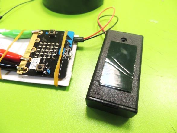
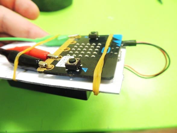
22. Make a remote control using the cardboard piece. Attach the Micro:bit using rubber bands, and the battery holder using mounting tap. Connect the alligator cables to the Micro:bit pins this way:
- P0: blue alligator
- 3V: red alligator
- GND: black alligator
Test
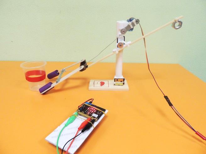
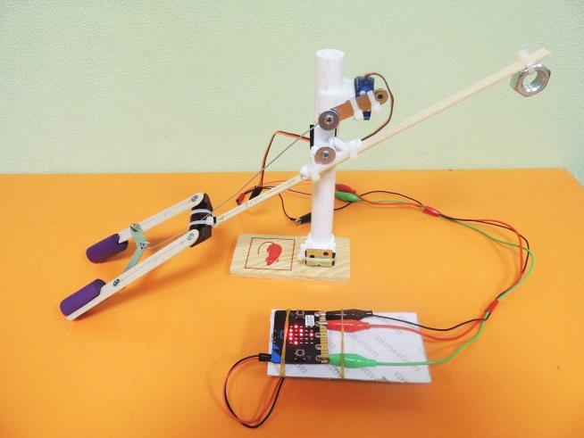
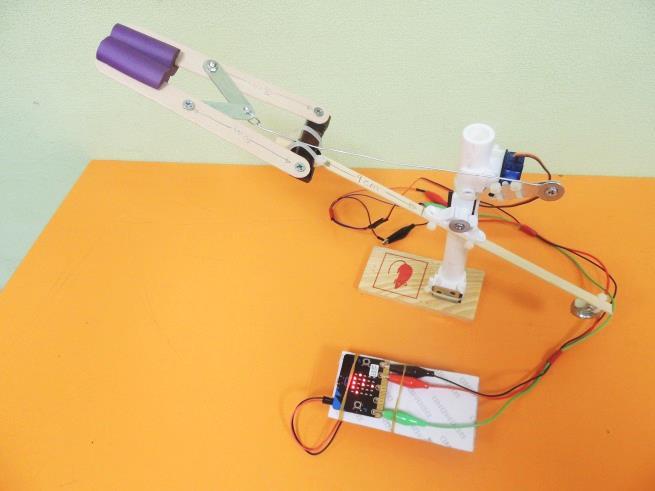
23. Now, time to test your robot arm. First empty handed, and then with the plastic cup. The robot must grab the cup and lift it when you press button A, and put the cup down when you press Button B.