Micro:bit MU Vision Sensor for Beginners - I2C and Shape Card Recognition
by Thorsgaard Efterskole in Circuits > Microcontrollers
2151 Views, 2 Favorites, 0 Comments
Micro:bit MU Vision Sensor for Beginners - I2C and Shape Card Recognition
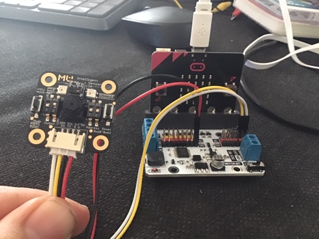
I have gotten my hands on a MU vision sensor for the Micro:bit. It seems to be a cool tool that will enable me to make a lot of different vision based projects. Sadly there doesn't seem to that many guides to it and while the documentation is really good in some place, it also have some deficits and the programming is not always intuitive. So to help others I am going to make a series of guides and projects.
Supplies
1 x BBC micro:bit
1 x Micro:bit breakout board - It needs to have access to pin 19&20, which not all breakout boards have. I use elecfreaks motorbit, because I like that board.
4 x Jumper wires (Female-Female)
Setting Up the Sensor
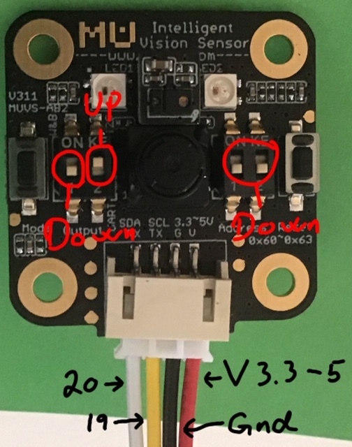
Before we start connecting anything we want to setup the sensor properly.
The Mu Vision sensor have 4 switches. The two on the left decides its output mode and the two one the right decides its address.
Since we want the address to be 00, both switches on the right should be turned off.
The different output modes are:
00 UART
01 I2C
10 Wifi data tansmission
11 Wifi picture transmission
We want to work in the I2C mode, so the two switches should be on 01, so the left most should be turned off and the other should be on.
Wiring
Wiring is pretty easy, just use four jumper wires to connect the Mu sensor with your breakout board.
Mu sensor -> Breakout board
SDA -> pin 20
SCL -> pin 19
G -> Ground
V -> 3.3-5V
Getting the Extension
.JPG)
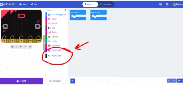
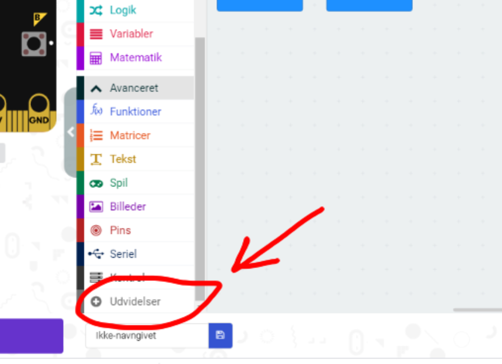
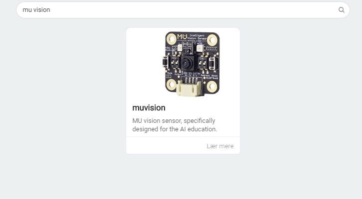
First we go to the Makecode editor and start a new project. We then go to "Advanced" and select "Extensions". Be aware that since I am danish, these buttons have slightly different names in the pictures. In extensions we search for "Muvision" and select the only result we get.
Initializing Connection and Enabling the Algorithm
.JPG)
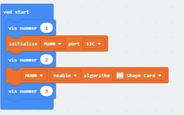
When you use this extension you will get some "Cannot read property of undefined" errors. That is just because the micro:bit animation is missing. It doesn't affect the compilation and runing of the program.
The first orange part of the code initialize the I2C connection.
The second orange part of the code enables the shape card recognition algorithms.
Showing numbers is used to trouble shoot. If the micro:bit doesn't count to three when you run the program, then check that your wires are connected properly to the right pins.
You can find the program here.
Detect Shape Card
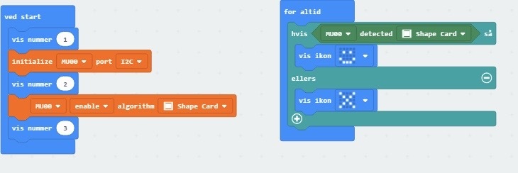
Detect shape card gives either a 0 or 1. If a shape card is detected we get an 1(true) and a 0(false) if a shape card is not detected. So if the Mu sensor detects a shape card we should get a smily face and if not, then we should get a frowny face.
You can find the code here.
Run the First Program
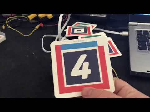
The Mu sensor kit includes different cards. Try holding them up to the sensor. It should be able to recognize the shape cards and give you a smily when you present it with one of them.
Detect the Shapes on the Cards
.JPG)
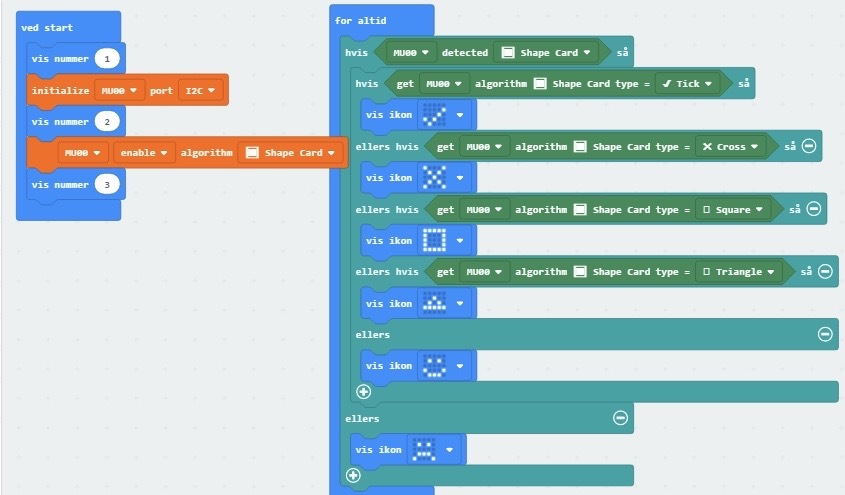
The "Get algorithm" give an output of either 0(False) or 1(True). When you use a "Get algorithm", then it will use the algorithm on your last positive "Detect". That is why in this program we have an outer IF ELSE statement that uses "Detect" and an inner IF ELSE statement that uses "Get algorithm".
The program should be able to recognize the specific shapes in the shape cards triangle, square, cross and tick and show the shapes on the micro:bit. Other shape cards it will recognize as shape cards and give you a smile for.
Find the code here.
Run the Program
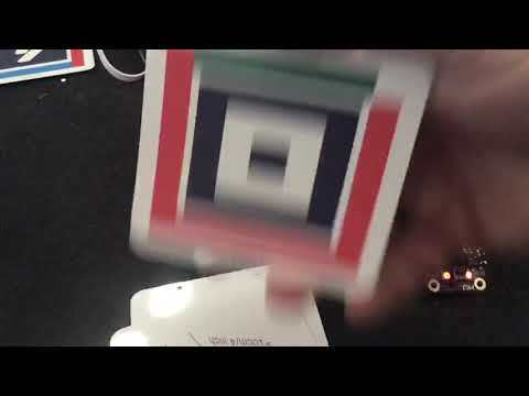
When you run the program the Mu sensor and micro:bit should be able to recognize the square, triangle, tick and cross shape cards. The other shape cards it will recognize as shape cards, but it will not show you what specific card it is. You can try expanding the program so it can recognize the last shape cards.