Micro:bit MU Vision Sensor - Tracking Objects
by Thorsgaard Efterskole in Circuits > Microcontrollers
1464 Views, 0 Favorites, 0 Comments
Micro:bit MU Vision Sensor - Tracking Objects
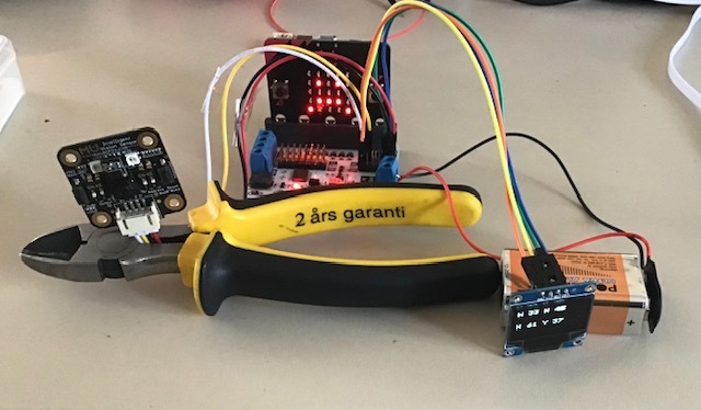
This is my fourth guide to the MU vision sensor for the micro:bit. Here I will go through how to track objects with the micro:bit and write the coordinates to an OLED screen. I have in my other guides gone through how to connect the micro:bit to the MU vision sensor and OLED and how to get the right extension, to program it. I will still explain that in this guide, but a bit faster.
Supplies
1 x BBC micro:bit
1 x Micro:bit breakout board - It needs to have access to pin 19&20, which not all breakout boards have. I use elecfreaks motorbit, because I like that board.
8 x Jumper wires (Female-Female)
1 x OLED screen
Step 1: Setting Up the Sensor
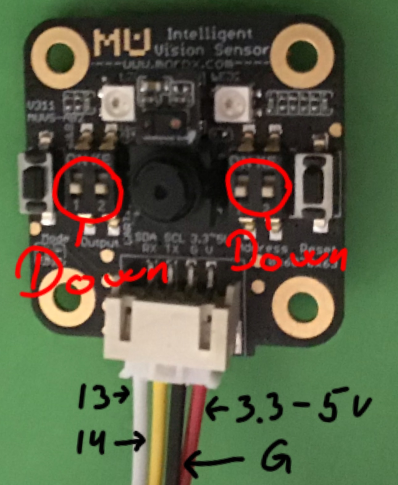
Before we start connecting anything we want to setup the sensor properly.
The Mu Vision sensor have 4 switches. The two on the left decides its output mode and the two one the right decides its address. Since we want the address to be 00, both switches on the right should be turned off. The different output modes are:
00 UART
01 I2C
10 Wifi data tansmission
11 Wifi picture transmission
We want to use a serial connection, because the OLED screen needs the micro:bits only I2C pins, so we are going to work in the UART mode. That means that the two switches should be on 00, so both should be on off.
Step 2: Wiring
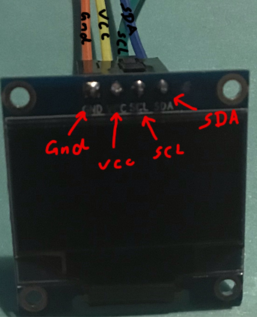
Wiring is pretty easy, just use four jumper wires to connect the Mu sensor with our breakout board. Look at the picture in Step 1 for help.
Mu sensor -> Breakout board
RX-> pin 13
TX -> pin 14
G -> Ground
V -> 3.3-5V
Then we use four jumper wires to connect the OLED with our breakout board.
OLED -> Breakout board
Vin -> 3.3 v
GND -> GND
SCL -> Pin19
SCD -> Pin20
Getting the Extensions
.JPG)
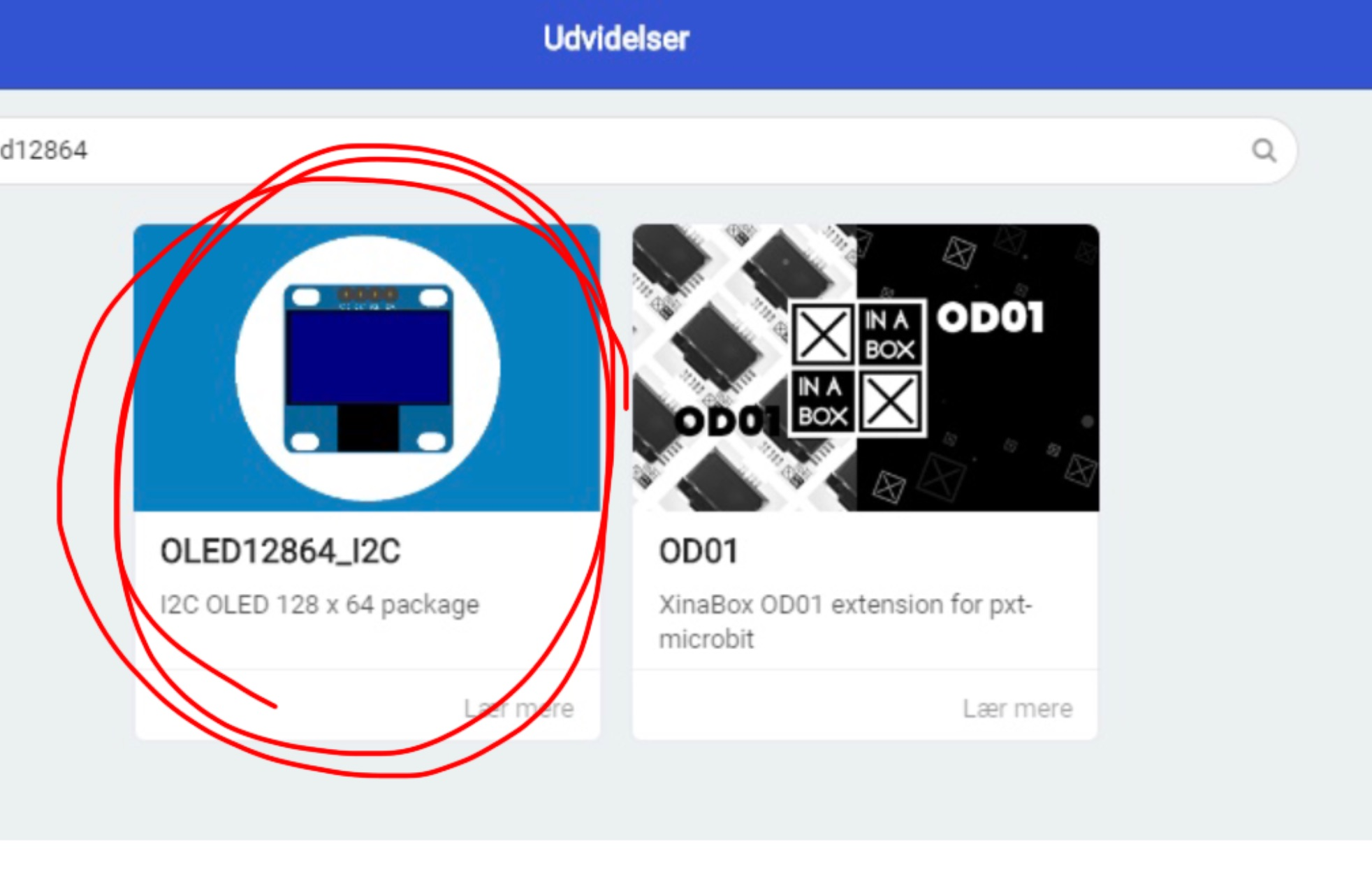
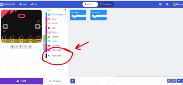
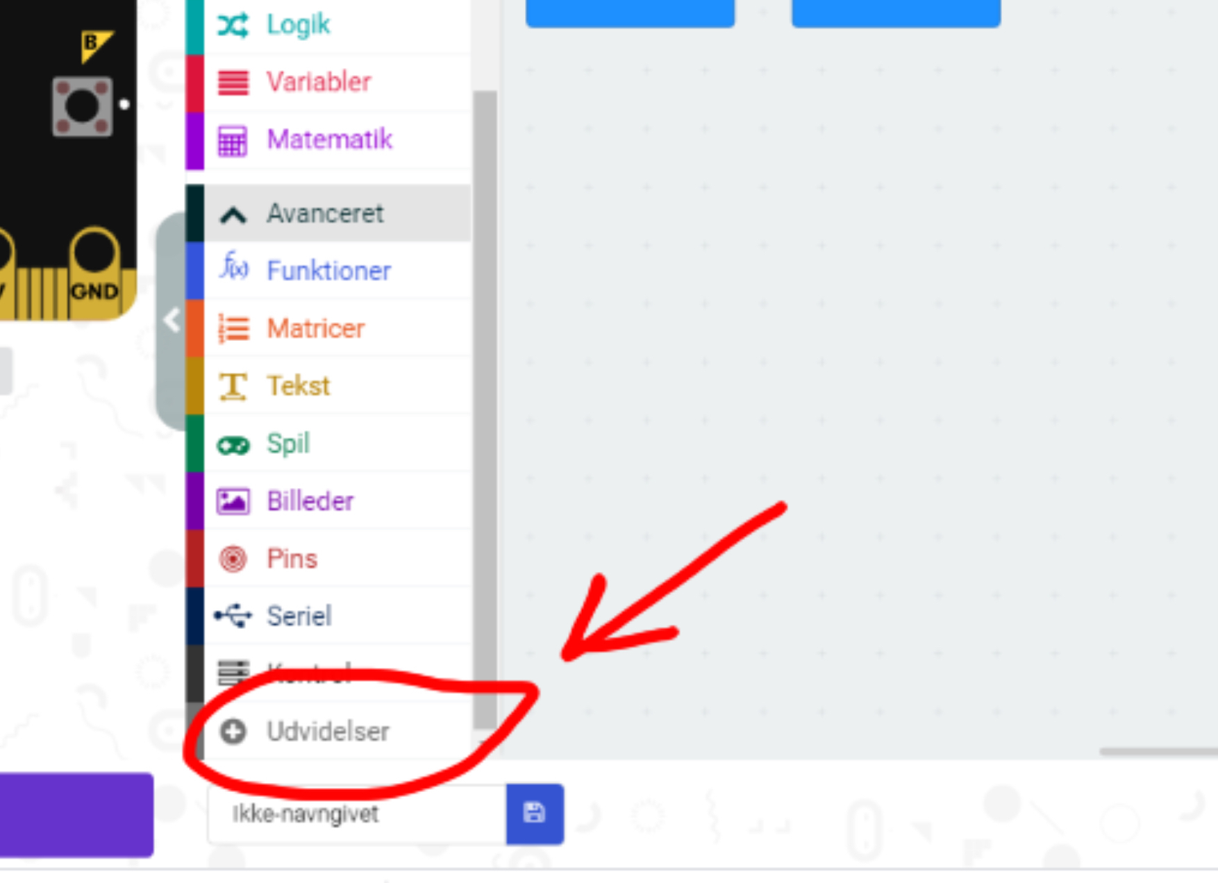
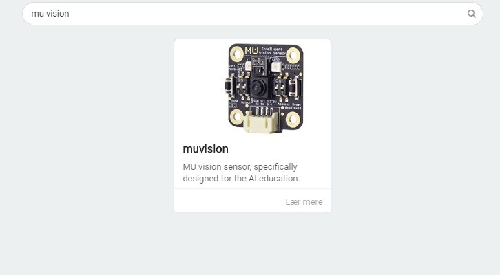
First we go to the Makecode editor and start a new project. We then go to "Advanced" and select "Extensions". Be aware that since I am danish, these buttons have slightly different names in the pictures. In extensions we search for "Muvision" and select the only result we get. We then go back into extensions and search for oled12864 and select the OLED12864_I2C extension.
Coding- on Start
.JPG)
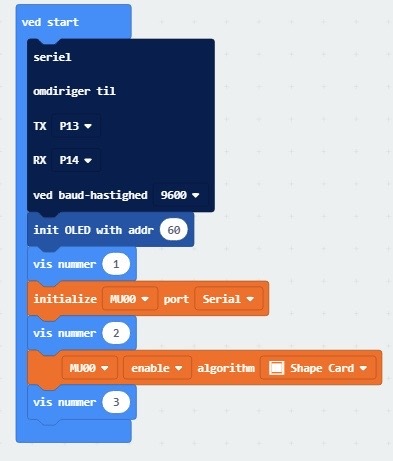
The first block in this program tells the micro:bit which pins it should use to make the serial connection. If you have used the same pins as I when you connected the MU vision sensor, then you want set TX to pin 13 and RX to pin 14. Baudrate, which is how fast the micro:bit and MU vision sensor is going to talk, should be set to 9600.
The next block initialize the I2C connection betwen the OLED screen and Micro:bit. The adress depends on the OLED hardware. It is most often 60, but for some OLED screens it might be 61 or other numbers.
I include the three show number blocks to help troubleshooting. For example if the micro:bit only counts to 2 on start up, then I know there is a problem with enabling the shape card algorithm. You can include a fourth show number block betwen the first and second block in the current program.
The next block, the first orange block, initialize the serial connection betwen the MU vision sensor and micro:bit.
Next block is a show number block for troubleshooting.
The next block, which should be the second orange block, tells the MU sensor to enable the Shape Card algorithms.
The last block is a show number block for troubleshooting.
Coding - Forever Loop
.JPG)
.JPG)
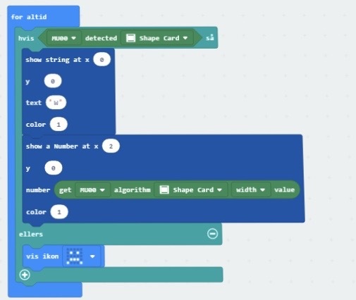
We start the program with an if-else block, with a deteck shape card block.
Detect shape card gives either a 0 or 1. If a shape card is detected we get a 1(true) and a 0(false) if a number card is not detected. We need to include that, because with our shape card algorithms will always run on the last detected shape cards. So if we never detect a shapecard, then we can't really run the algorithms.
The first block in the truth statement tells the OLED screen to write a W(For width) in the top left corner of the screen. Position (0,0).
The next block tells the OLED screen to write the number it get from the shape card witdth algorithm to the right of the W. Position (2,0). This number tells us how width the shape card is.
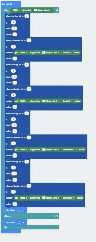
The program continues like this.
First a block that tells the OLED screen to write a letter. H for Height at (5,0). X for the X-position value at (0,2). Y for the Y-position value at (5,2)
Then a second block that tell the OLED screen to write a number it gets from the shape card algorithm. The cards height at (7,0). The cards X-position at (2,2). The cards Y-position at (7,2).
So when we run the program and the MU Vision sensor detects a shapecard it will give us the cards width, height and position.
The full program can be found here.
Testing
It might be a bit hard to see on the video, but when I move the card from side to side the X-value changes. Moving the card up and down changes the Y-value. Moving the card closer to and away from the MU vision sensor changes the height and width values.
It is pretty easy to use this program to detect other things. Just change the "shape card" to what you want to detect. It should work with colour blocks, balls, bodies, number cards and traffic cards.