MicroSumo (100g) Competition Robot
by m_piotrowicz in Workshop > Electric Vehicles
1288 Views, 4 Favorites, 0 Comments
MicroSumo (100g) Competition Robot


Hello!
In the following instruction I would like to lead you through the process of construction of the Micro Sumo class robot. Showing you also some tricks I will try also to make it more accessible to produce a robot like mine.
When it comes to the robot itself, it is a competition construction which basically has to work fully autonomous, fit within the size of 5x5x5cm and weigh no more than 100g. Its goal is to locate the opponent robot on the circle dohyo and push it out, winning the battle.
I will not however provide you a full instruction of using every computer programme I used here, because the instruction would be too vast… Maybe next time ?
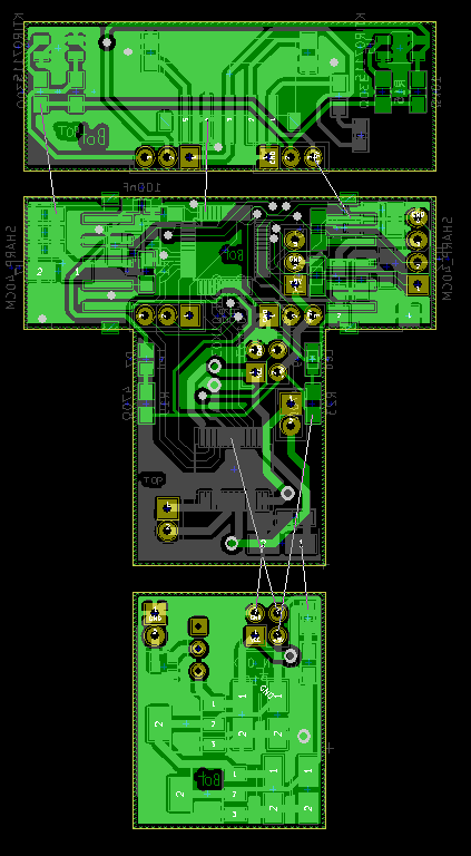
To make yourself prepared right now I can say I used Inventor for basic project of the cover, which was 3D printed afterwards. For the electronics project, I made from a real scratch, I made a use of KiCad first, then generating proper .gerber files.
Meanwhile, I was typing the C programme for the robot using a set of STM32CubeMx, Workbench based on Eclipse plus a ST-Link Utility in order to programme the microcontroller put on the PCB.
Electronics


Concerning the electronical components I made a use of, the whole construction depends on:
- A microcontroller STM32F051C8T6 in LQFP48 package. Its basic features are 64kB of flash memory capacity and Clock frequency 48MHz
- Toshiba TB6612 double motor controller, being just right for the robot that light, as the current does not exceed the value that could harm it.
- Digital IR proximity sensors – Sharp GP2Y0D340K with the range of 40cm. I managed to get about 25cm of practical range.
- I also put KTIR0711S sensors to detect the white line, but they became not practical during the tests, so they just do not work.
Moreover I used 2 LM1117 voltage stabilizers to get the levels of 5V (for the sensors) and 3V3 (for the logic operations on the microchip or another devices). Of course I stayed with the default voltage of the battery (7.4V, max. 8.4V) to power the motors.
Anyway I am posting the whole documentation of connection schematics alongside with the PCB design itself. I know I do not describe here every single wire on the board whatsoever. Just let me know f anything is not clear to you.
The Programme


The C-language code itself is really simple, yet reaaally practical as I have already seen. It consists of a few simple IF-conditions. For instance if only right sensor “sees” something in its range (and gives a low state on its output / microcontroller input) the robot turns right using 50% of the maximum voltage to stay precise. If there is an opponent on the front, it goes straight ahead. If there is nothing in the range of the sensors, the robot should turn again till it finds the opponent. One final option is to have the opponent visible on both front and side sensor – the robot then should make a turn but not as sharp as previously. To do so, we make the both motor turn the same way, forcing however one to go faster than another.
Mechanical Parts
As for the mechanical parts, I used micro Pololu motors 50:1 with 3D
printed wheels and tyres made out from a modelling silicon mixture. To make the construction weigh the maximum 100g I simply put some lead under the cast with use of epoxy glue.
Yes, It Is That Simple
That is basically it, when it comes to me constructing a MicroSumo
robot. It is simple, yet I managed to win 3 silver and 2 bronze medals on worldwide competition up today ? If you would like to make your own, feel free to ask about anything here ?
See you next time!