MicroLock
.jpeg)
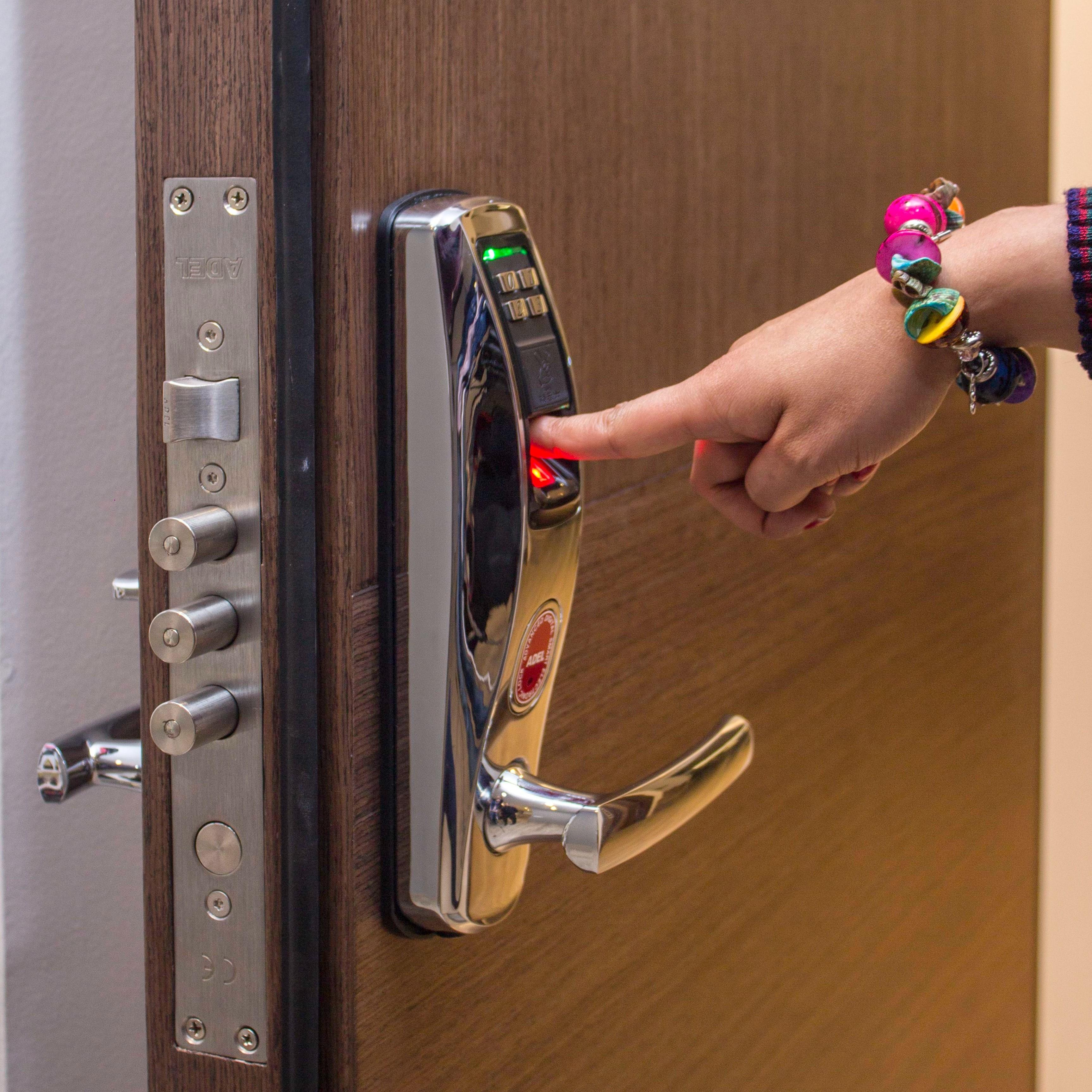
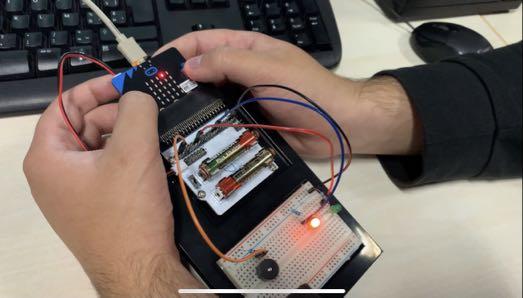
This is a code lock that you can open using the 2 buttons A and B.
This is how it works:
When the user presses A, the microbit light changes to the next one. When you then press B you can select a certain light. If you select the 3 preset lights in the right order, you can open the lock with A + B.
Supplies
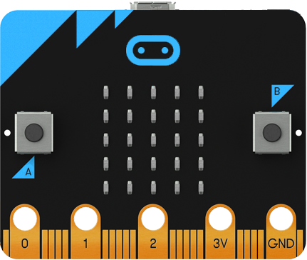
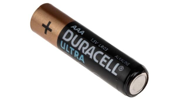
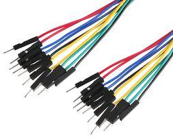
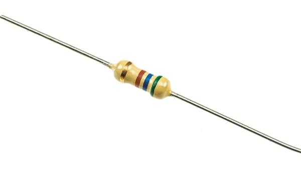
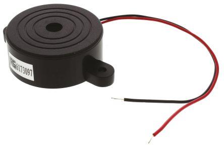
- 1x micro:bit
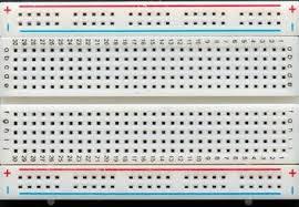
- 1x breadboard
- 2x battery
- 3x female to male jumper wires
- 2x resistor (470Ω)
- 1x buzzer
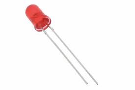
- 1x red, 1x green led light
Create These 6 Variables
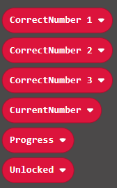
Go to variables and create these 6 variables.
Program Button: A
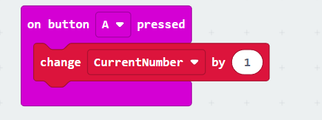
Now make sure that when the button 'A' is pressed that the variable 'CurrentNumber' changes by 1.
Program: Start
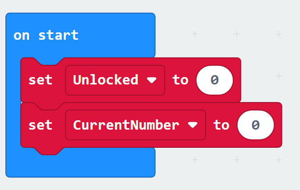
At the 'on start' just set 'Unlocked & CurrentNumber' to 0.
Program Button: A+B
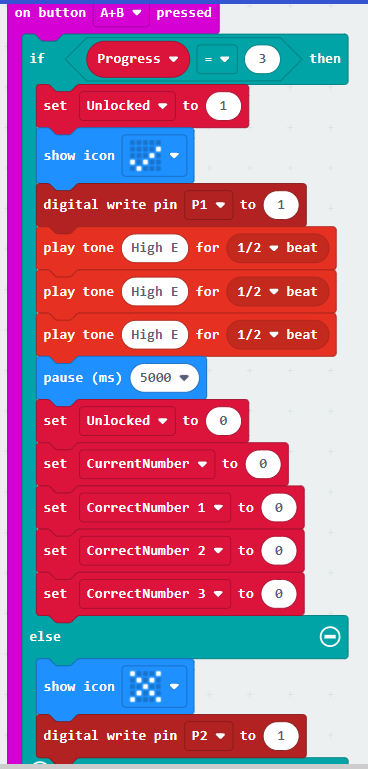
Now program the A+B button.
You do this by indicating that when 'Progress' = 3 the computer has to execute a number of instructions. This code ensures that the lock opens if you have entered the correct combination.
Program Button: B
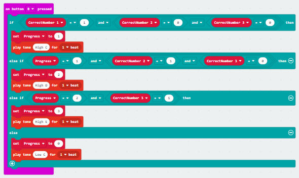
This is the code for the 'B' button.
This code ensures that if the correct LED is selected in the correct order, the 'Progress' will be 3.
Program: Forever
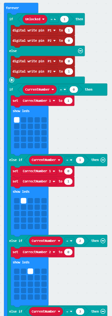
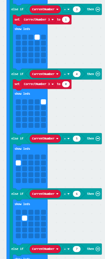
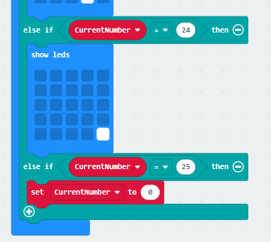
This is the "forever" code. The micro:bit checks this code constantly.
First you set if 'Unlocked' = 1 then you set a certain pin to 1. Then you do the same thing over and over. If 'CurrentNumber' = (1 to 25) then else set 'CurrentNumber' to 0. Then you put 'CorrectNumber 1, 2,3' on the LEDS you want. Just look at the code below
Connect Everything
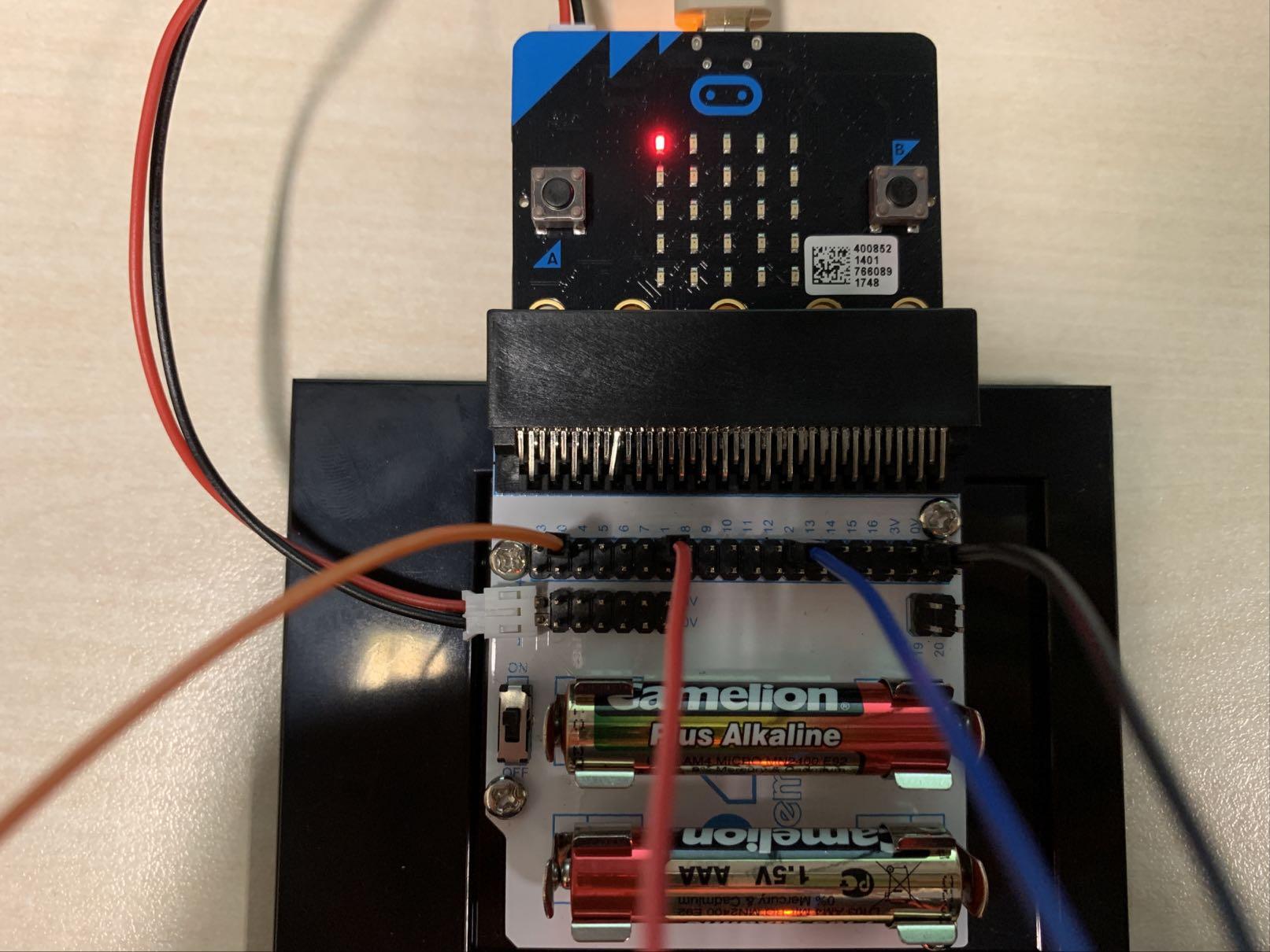
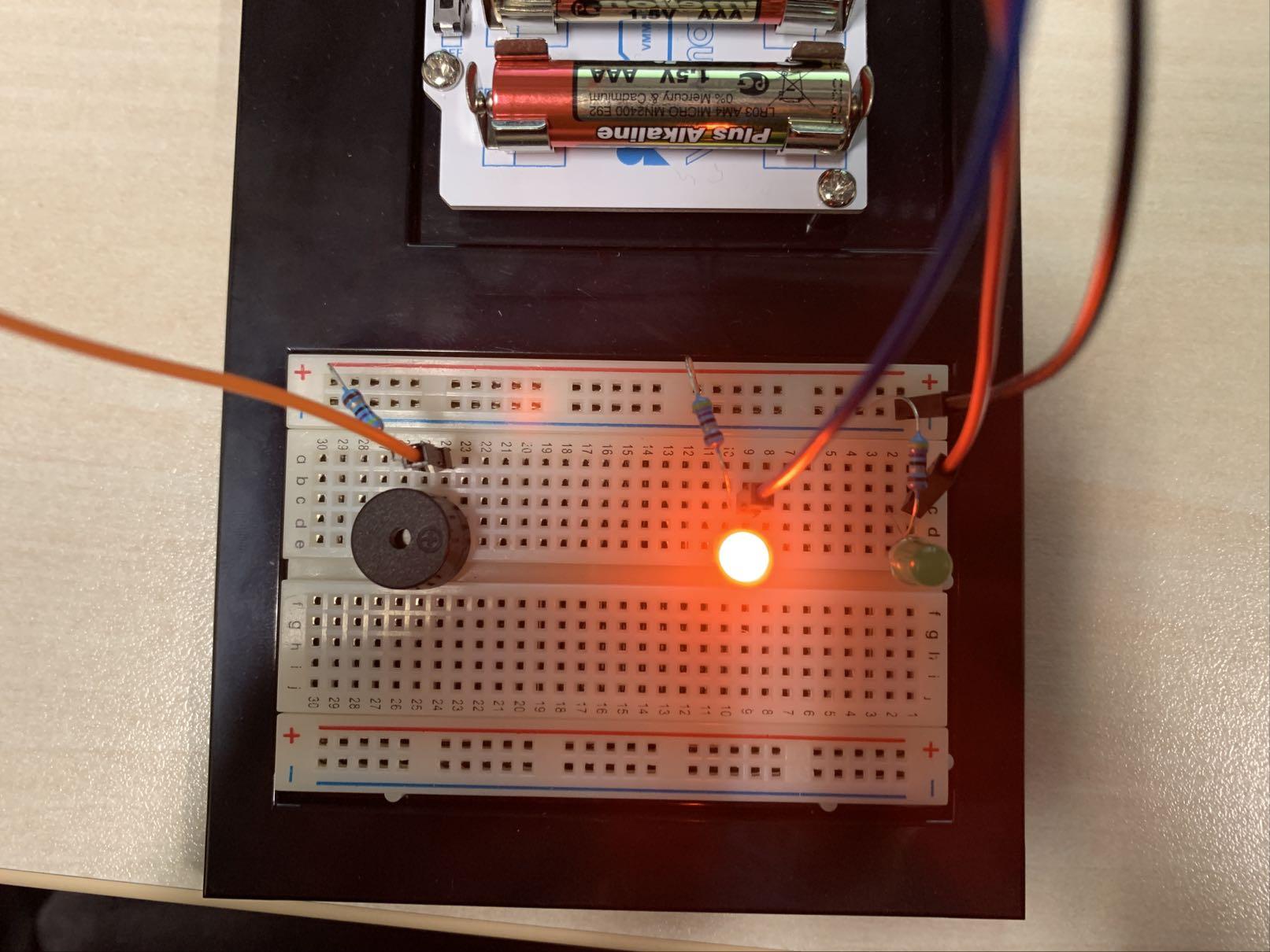.jpeg)
Now you are done with the code.
All you have to do now is connect all the wires like this and your MicroLock is finished!
Start with connecting the microbit with a battery. After that I put the microbit in a beadboard adapter.
1) connect pin 0 to 24a on the breadboard;
2) connect pin 1 to 1c on the breadboard;
3) connect pin 2 to 9c on the breadboard;
4) connect 0V to negative on the breadboard;
5) connect the transistors like in the pictures;
6) connect the buzzer and LED's with the breadboard like in the pictures.
Finished
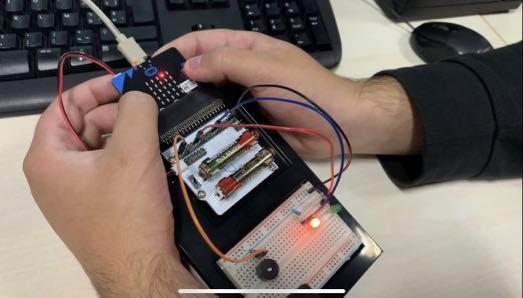.jpeg)
Now the MicroLock is ready to be used.