Micro:Bot - Micro:Bit
by Aidan-Corrales in Circuits > Electronics
1481 Views, 3 Favorites, 0 Comments
Micro:Bot - Micro:Bit
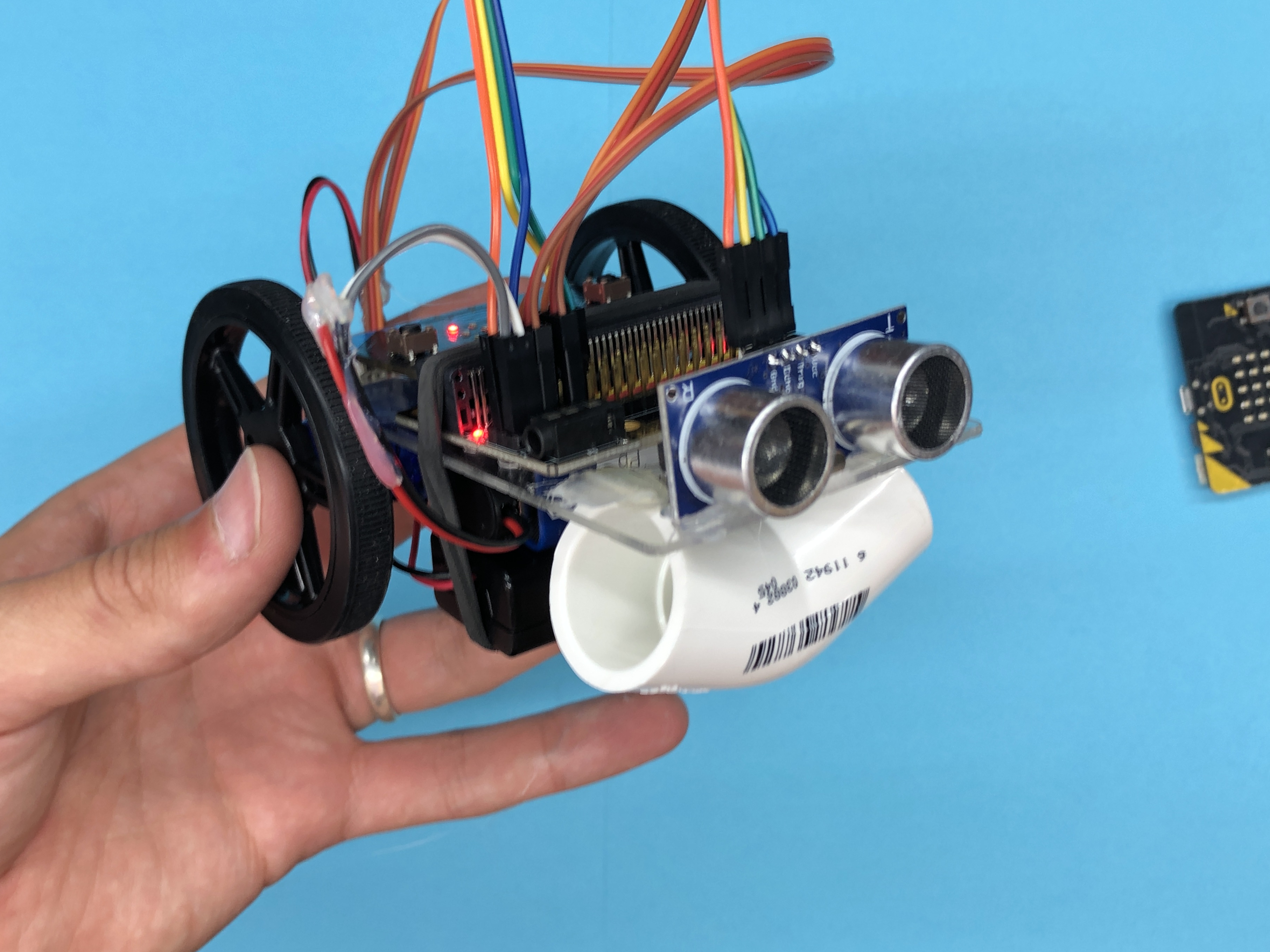
Build yourself a Micro:Bot! It is a Micro:Bit controlled robot with build in sonar for autonomous driving, or if you have two Micro:Bits, radio controlled driving!
Supplies
- Yourself
- Micro:Bit
- Battery Pack
- 9v Battery with DC adapter
- Ultrasonic Sensor
- Jumper Wires (4 x Female to Female & 2 x Male to Female)
- 2 x Continuous Servos
- 2 x Servo Wheels
- PVC Elbow (Used for caster, roughly 1")
- Micro:Bit Expansion Board
- Mounting Plate (3D Print Coming Soon!)
- Rubber Band
- Mirco USB
- Computer
Tools:
- Glue Gun
- Scissors (Or wire stripper)
- Phillips Screwdriver (Optional)
Make Sure You Have All Your Parts!
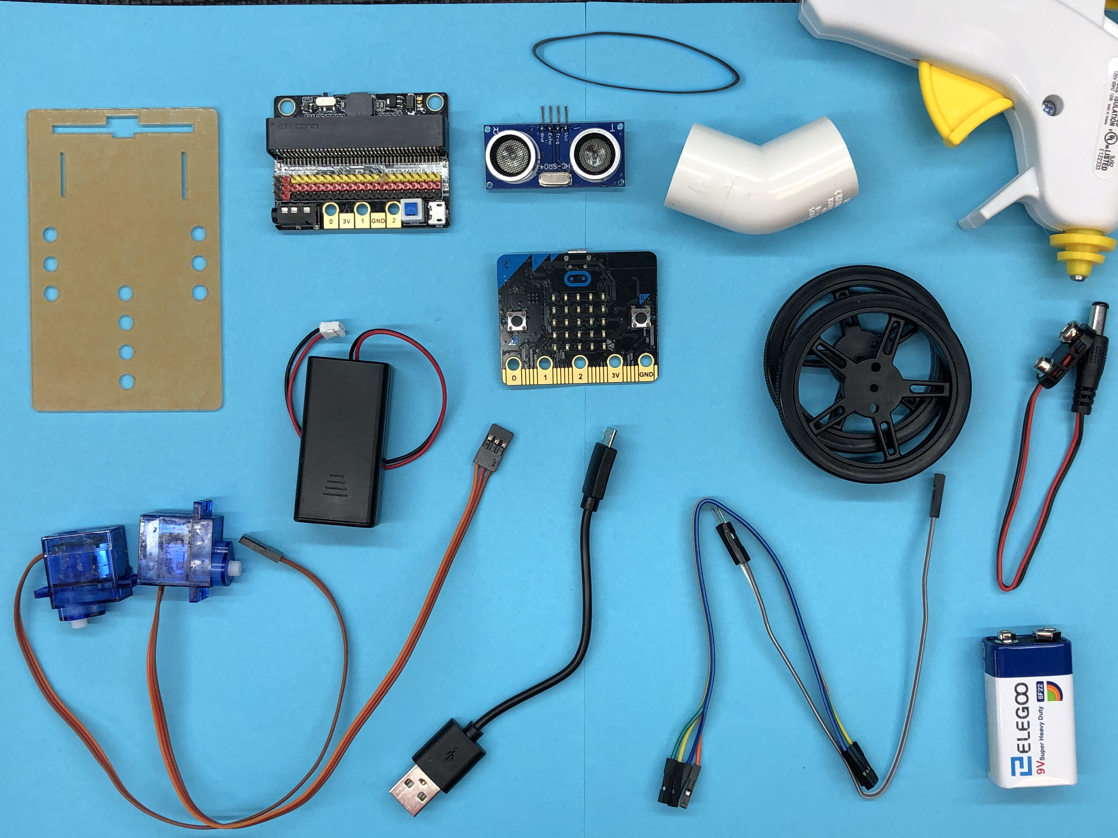
Some parts, such as wire adapters or PVC elbow can be substituted. Go ahead and read through the instructions to see if you can work without anything you may be missing!
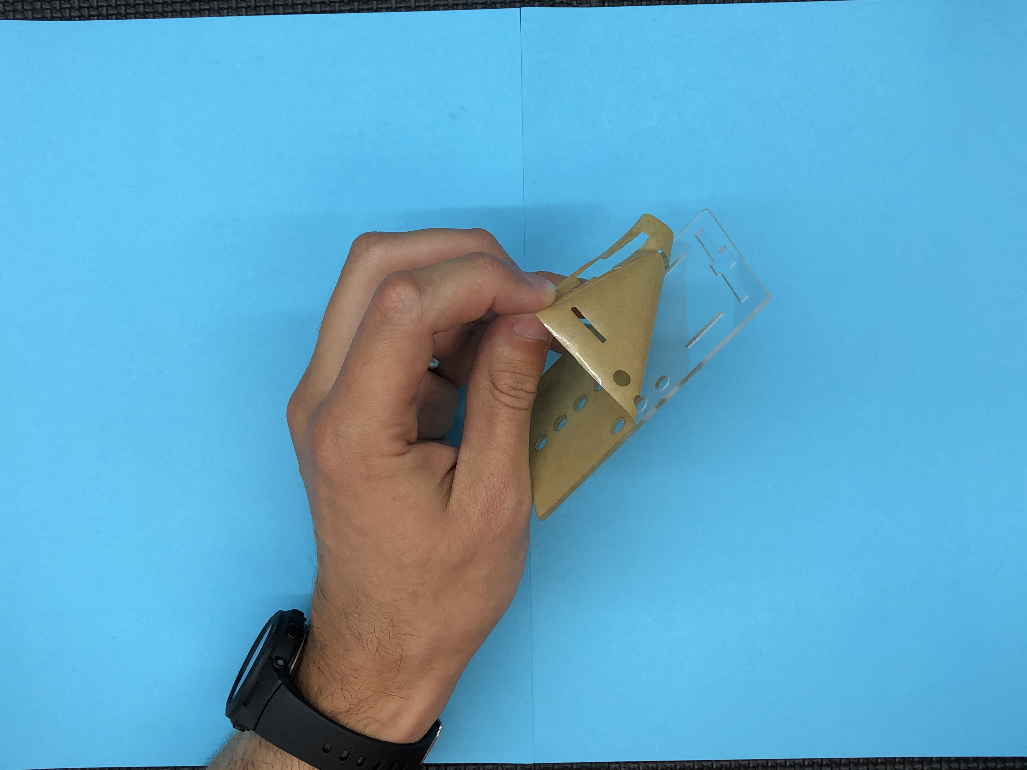
Peel the Protective Cover Off of Your Mounting Plate!
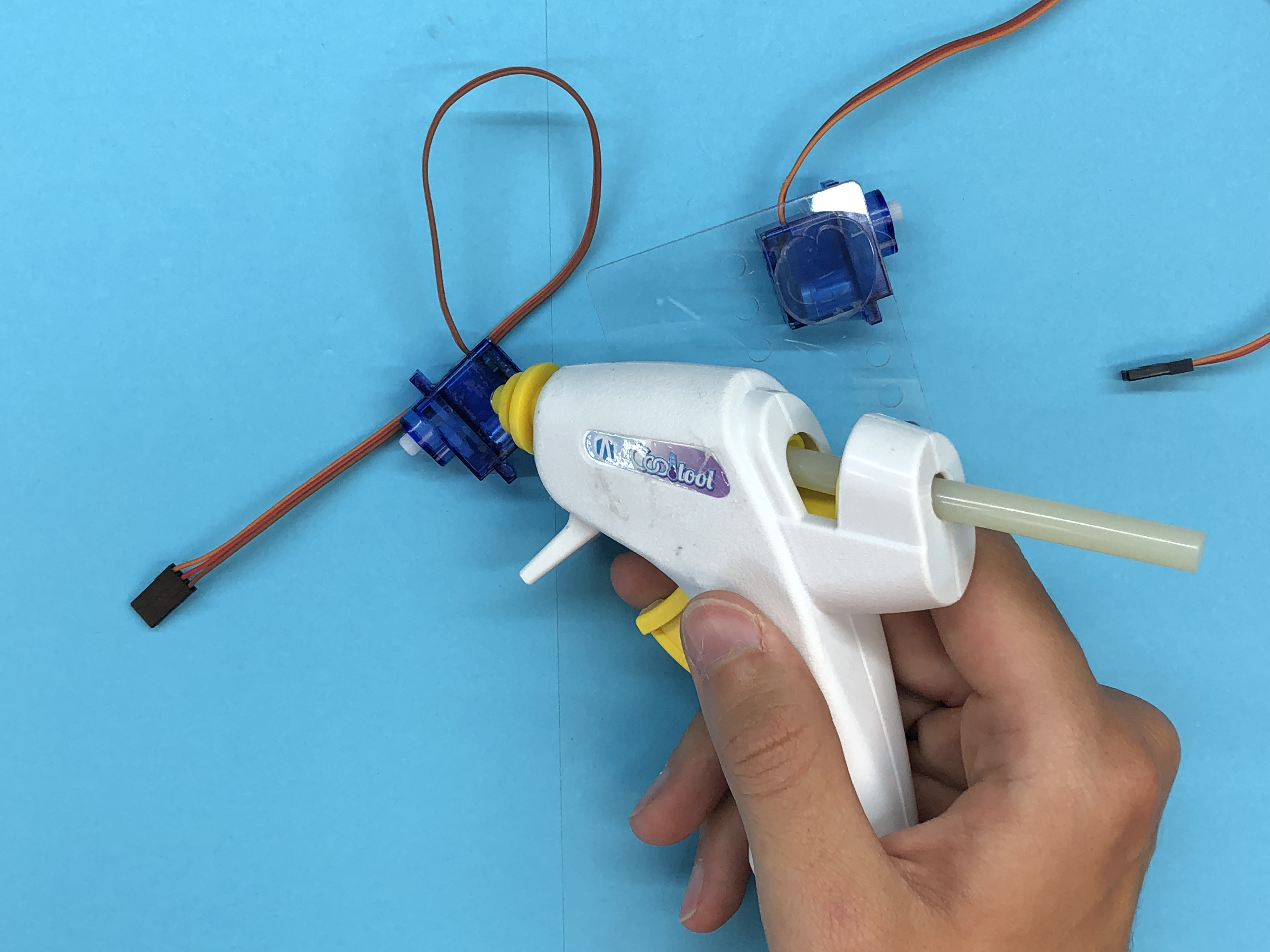
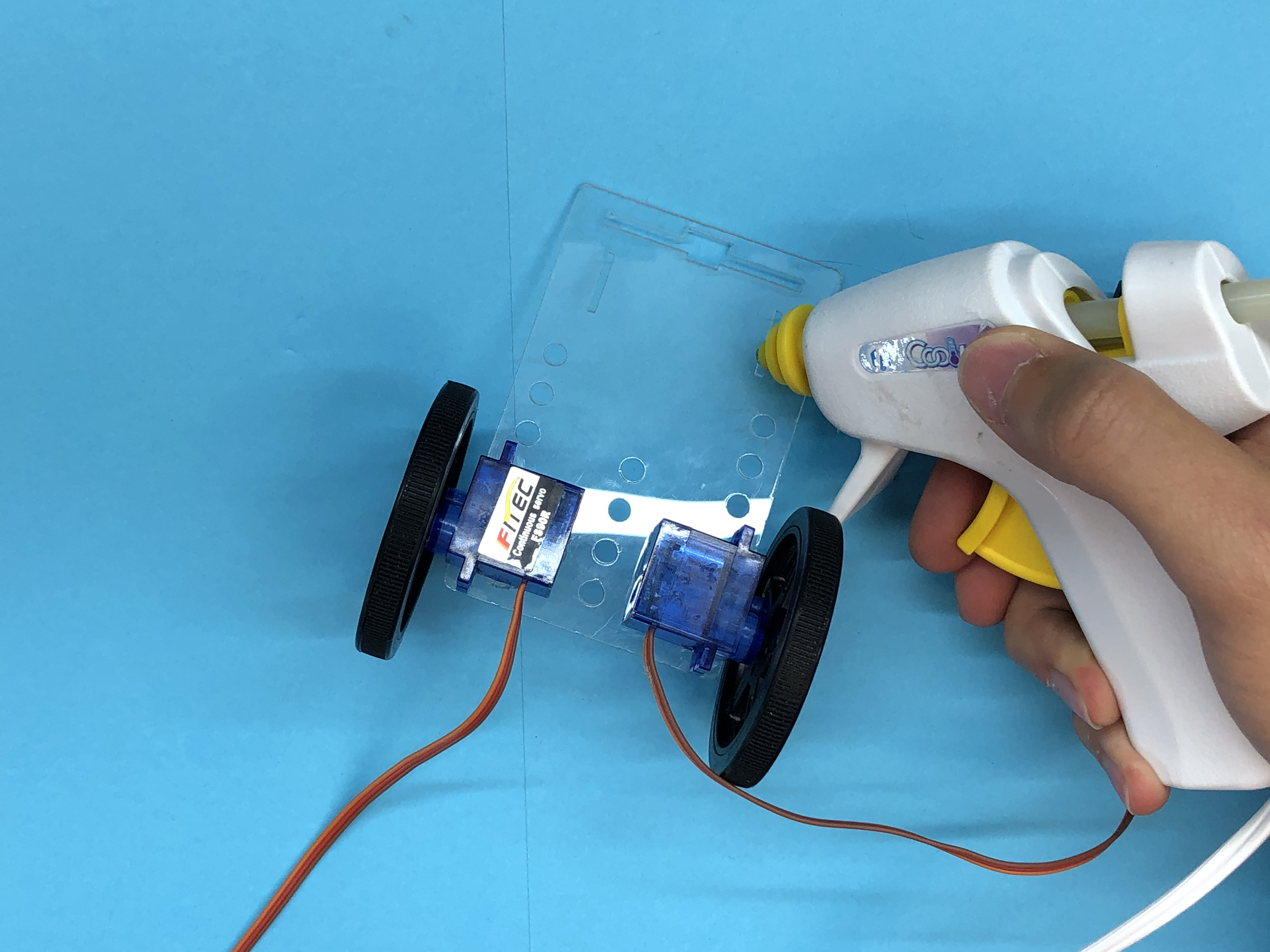
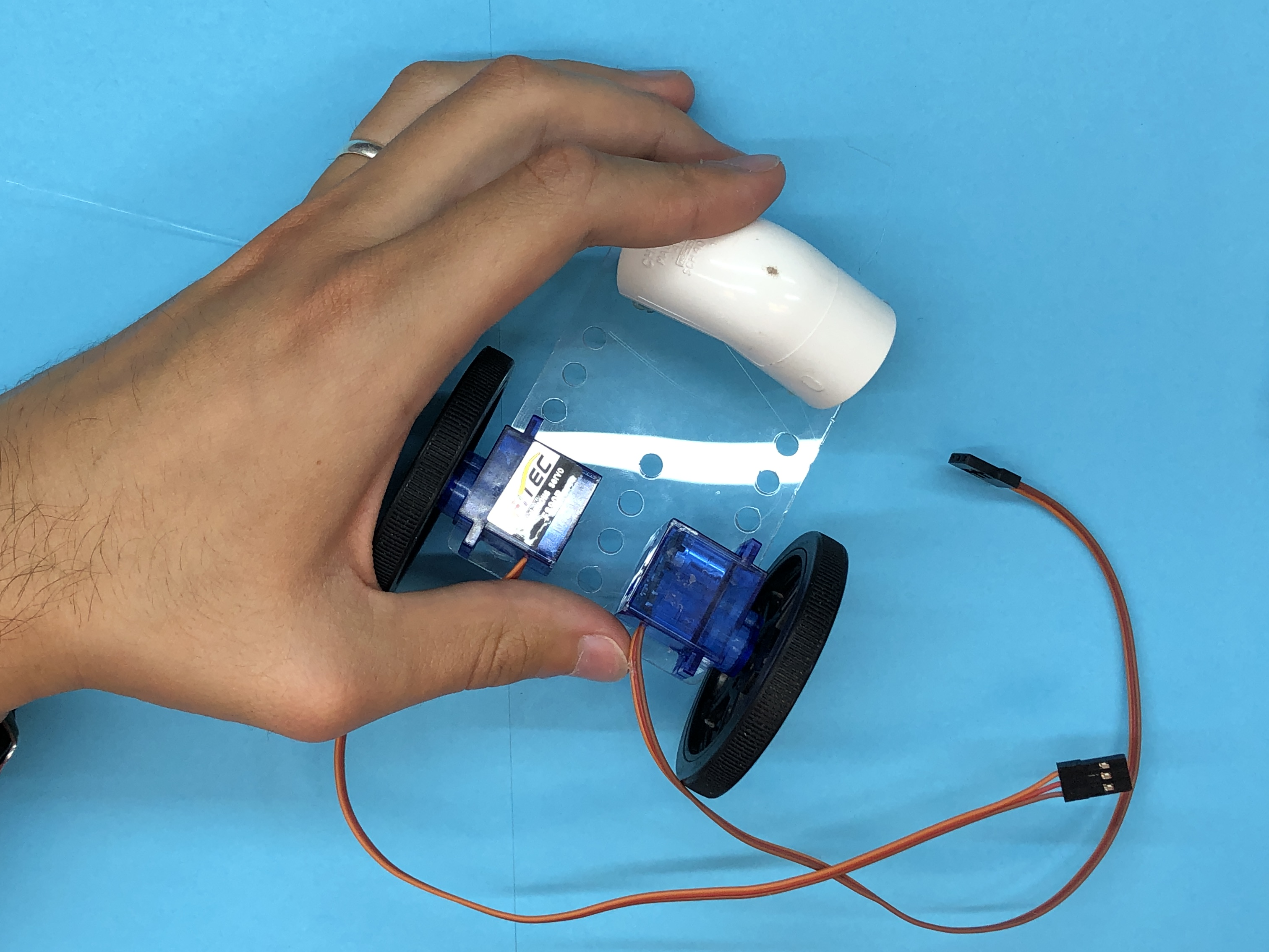
Mount Motor #1!
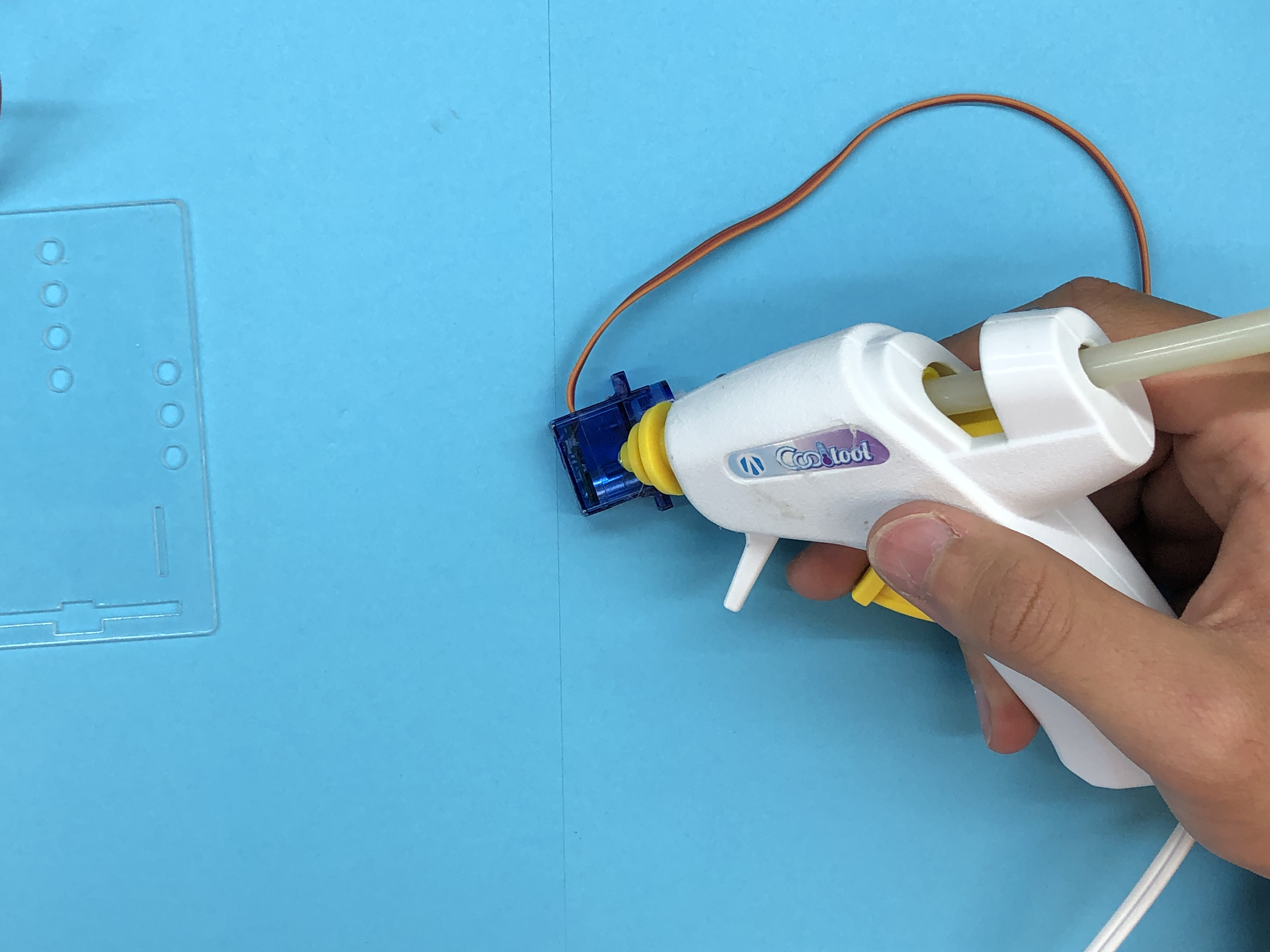
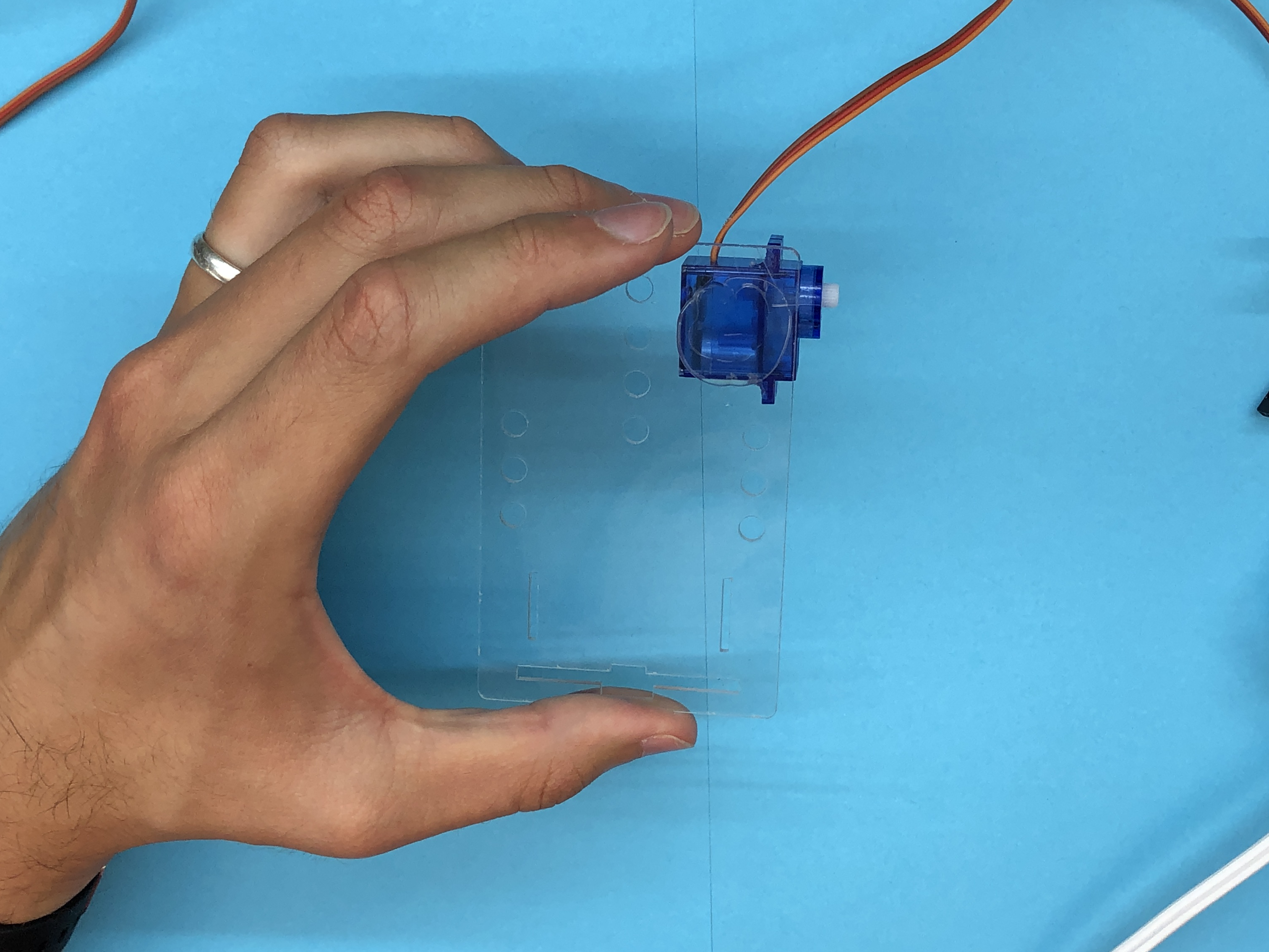
Add hot glue to your servo and mount it to the upper right corner of your mounting plate facing outward.
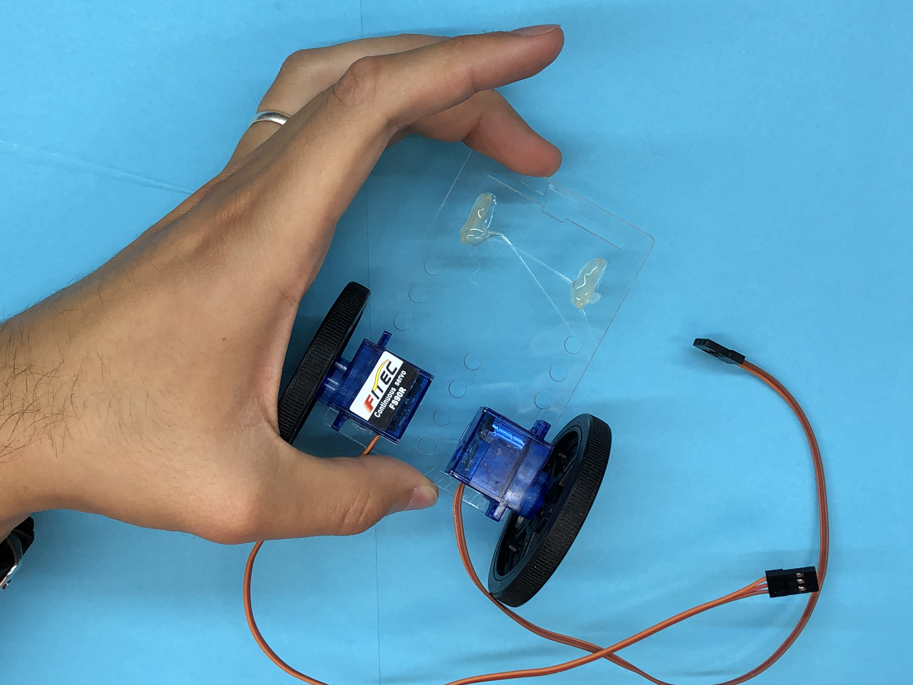
Mount Motor #2!
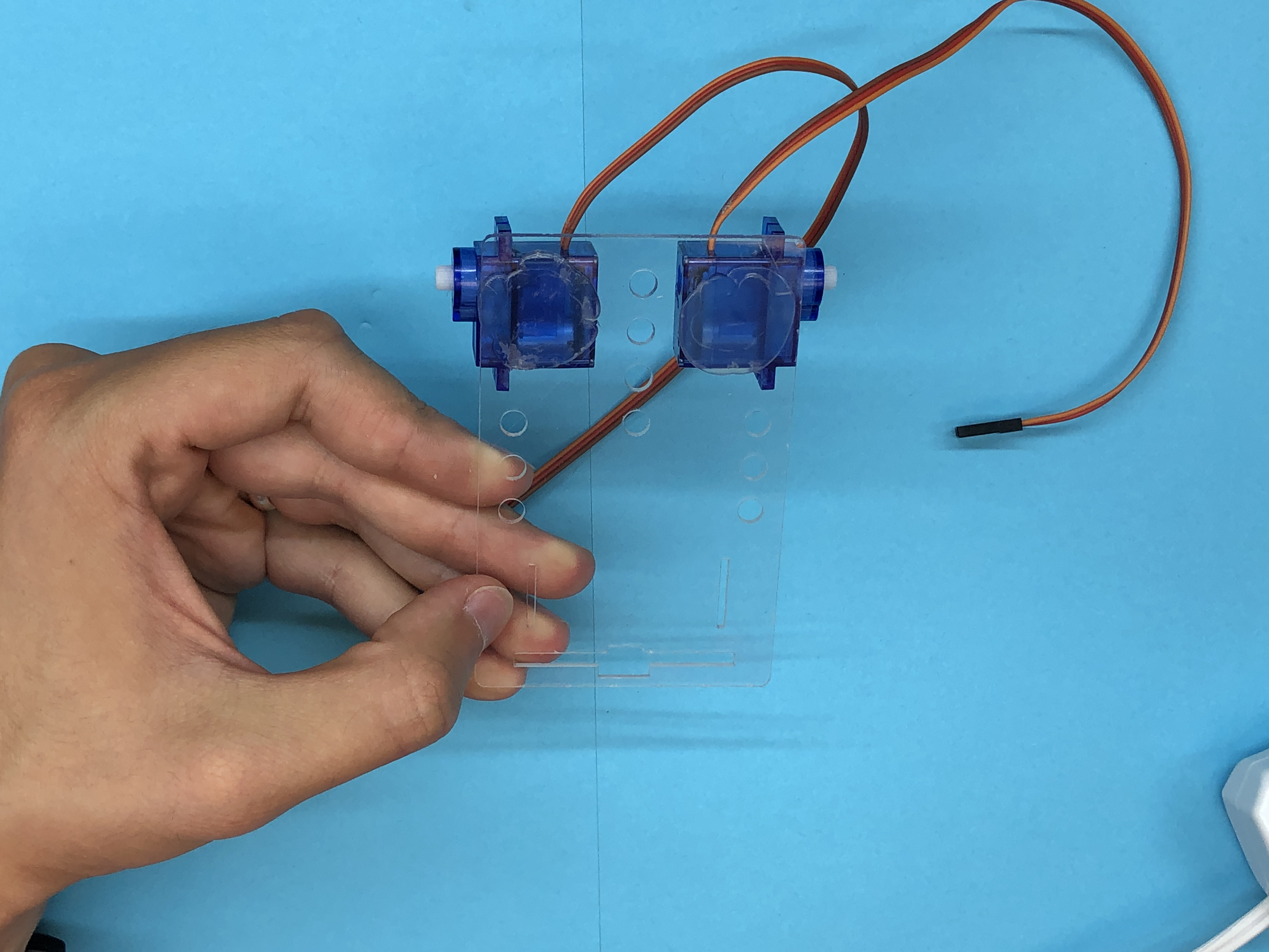
Add glue to your second servo and mount it mirrored of the other in the upper left corner.
Attach Your Wheels!
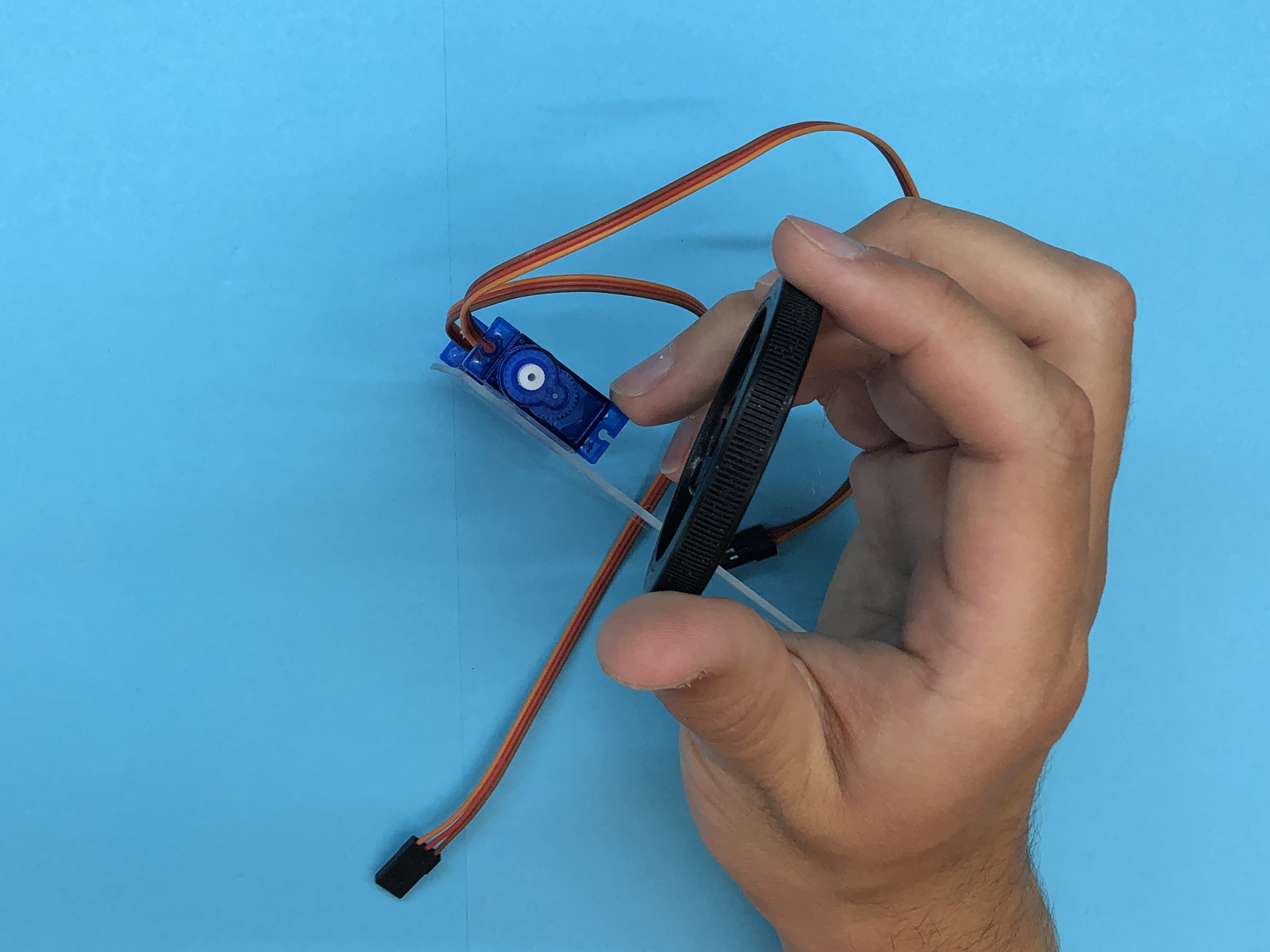
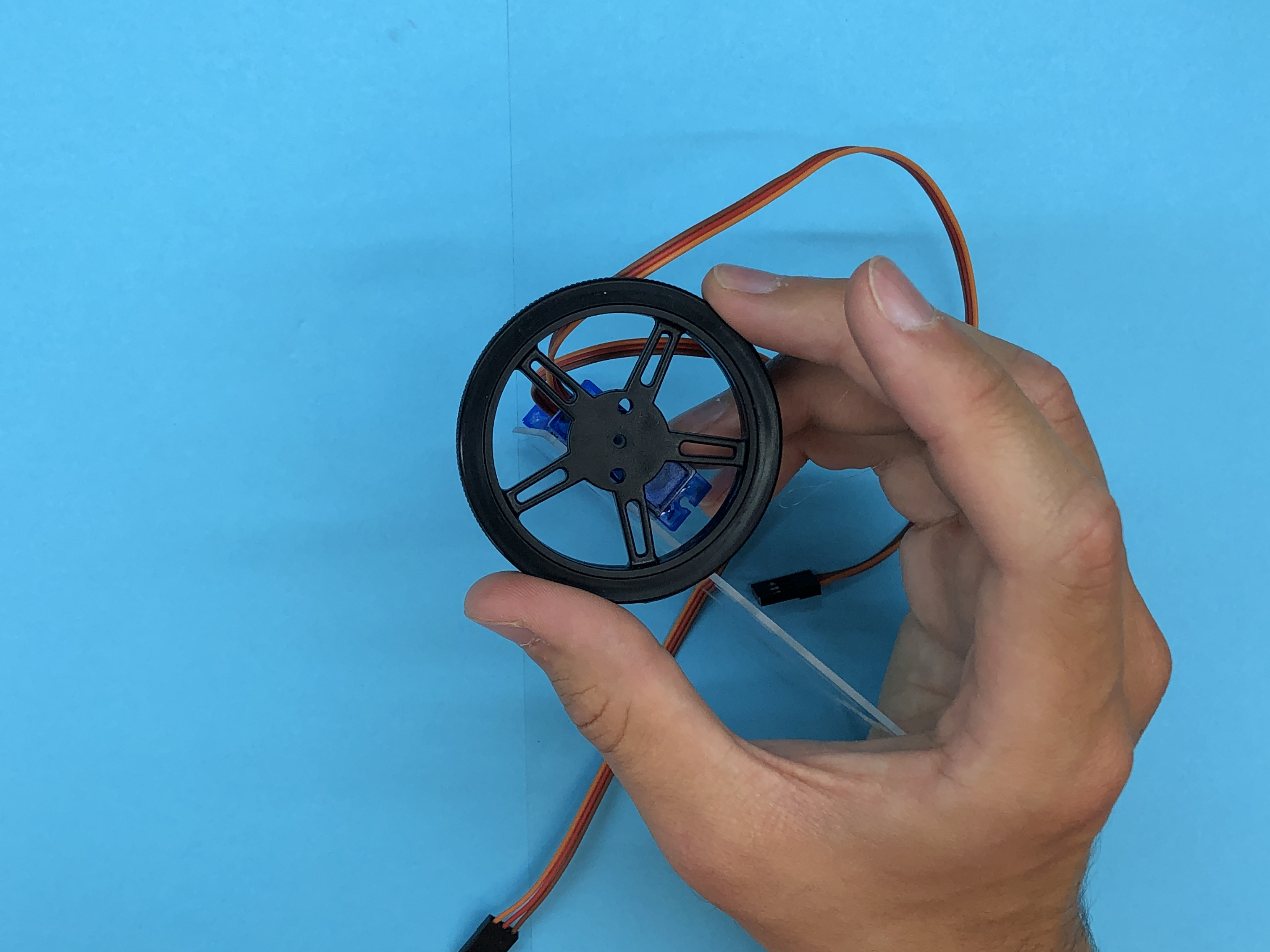
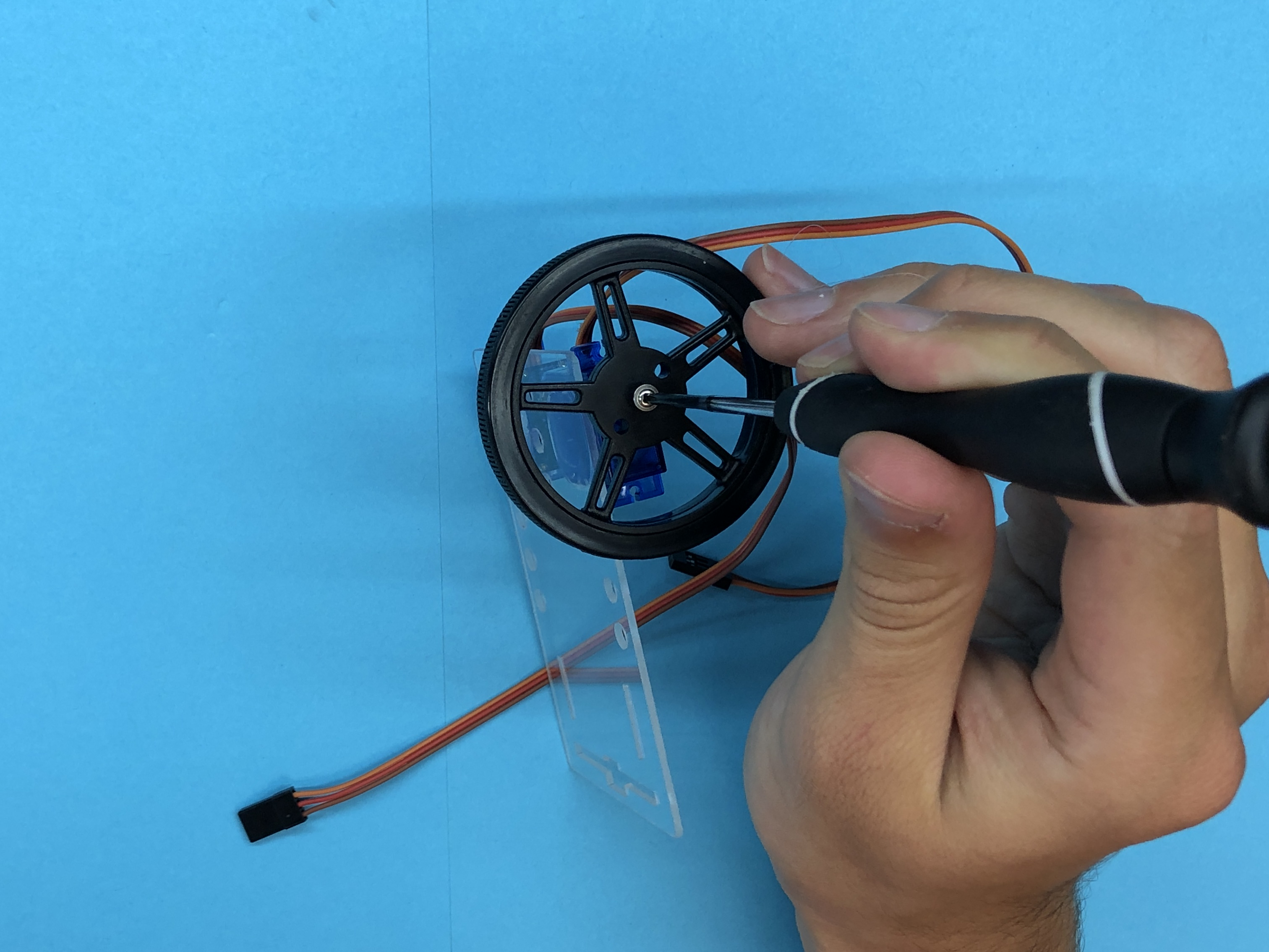
Put the wheels on both servos. If you have a phillips head screwdriver, go ahead and screw the wheels in. If you cannot, they should still work fine.
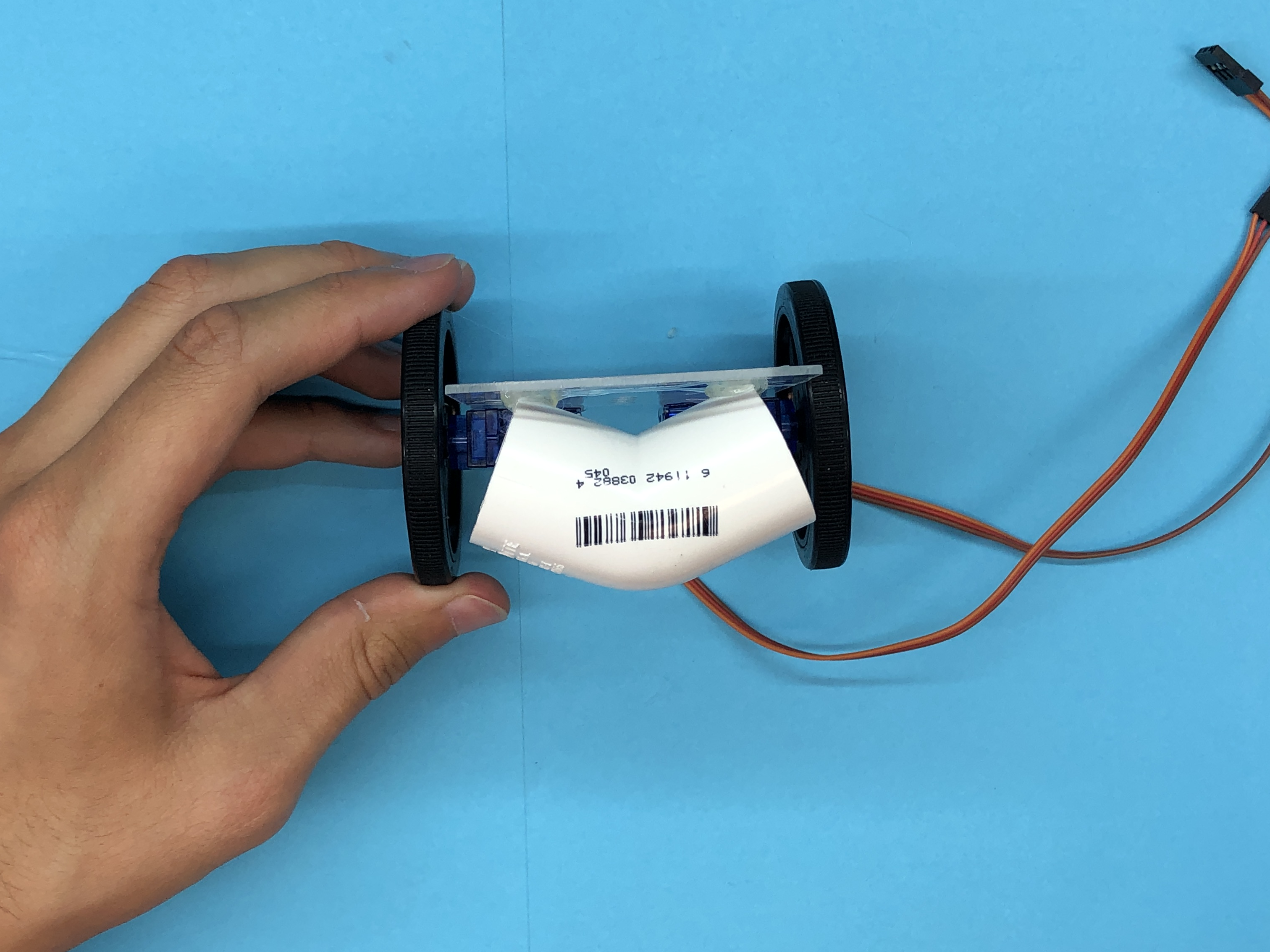
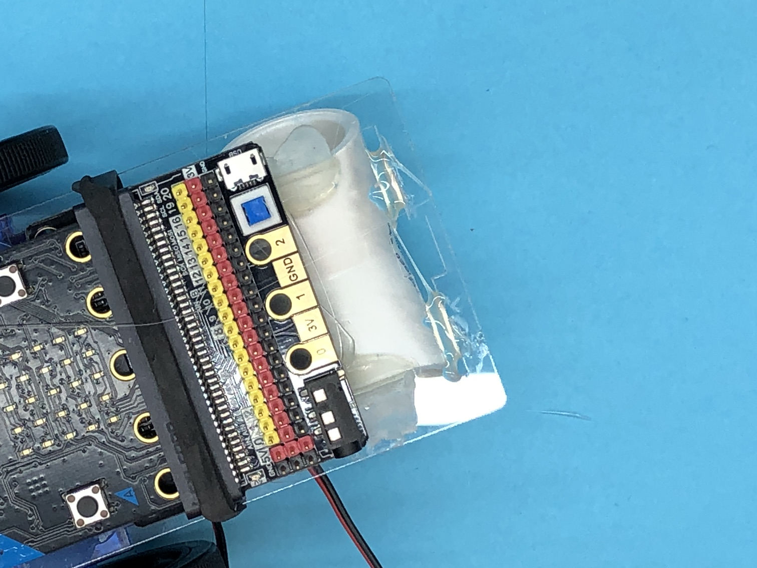
Caster
.png)
.png)
.png)
.png)
Use your PVC elbow as a caster. Add glue to the two slots at the front of your board and place your elbow so that is touches the ground at the same level as your wheels.
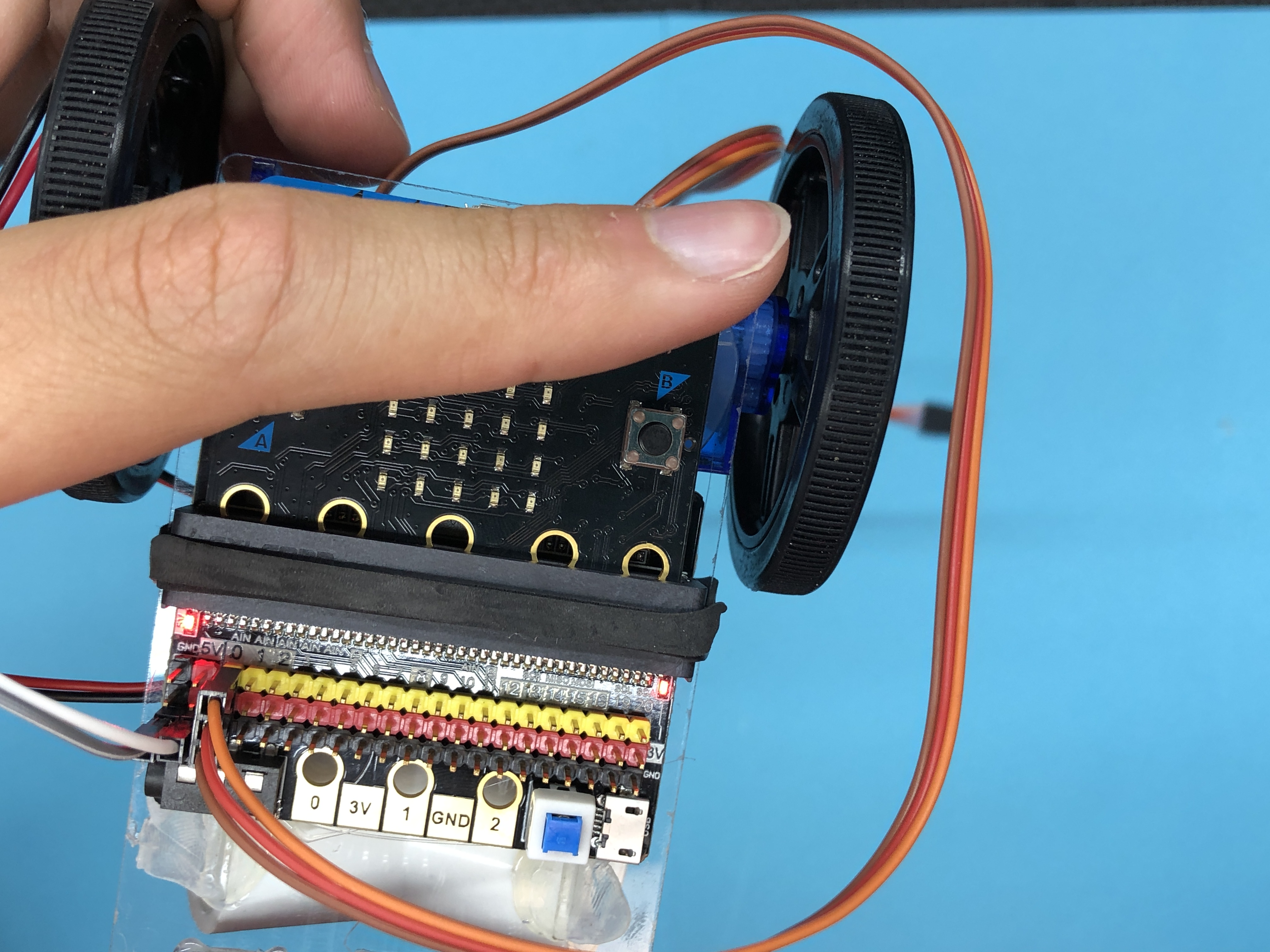
Add Micro:Bit and Breakout Board
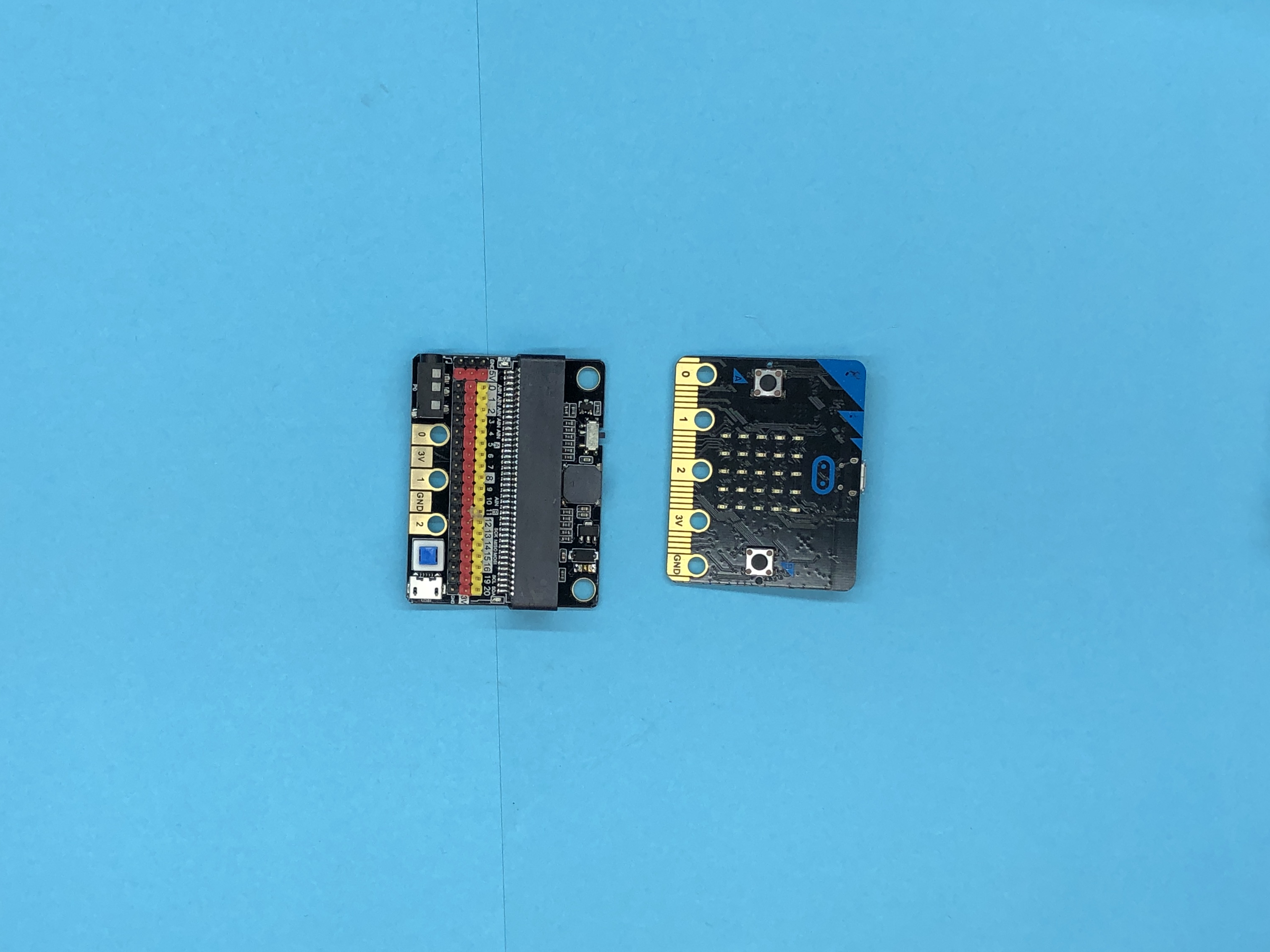
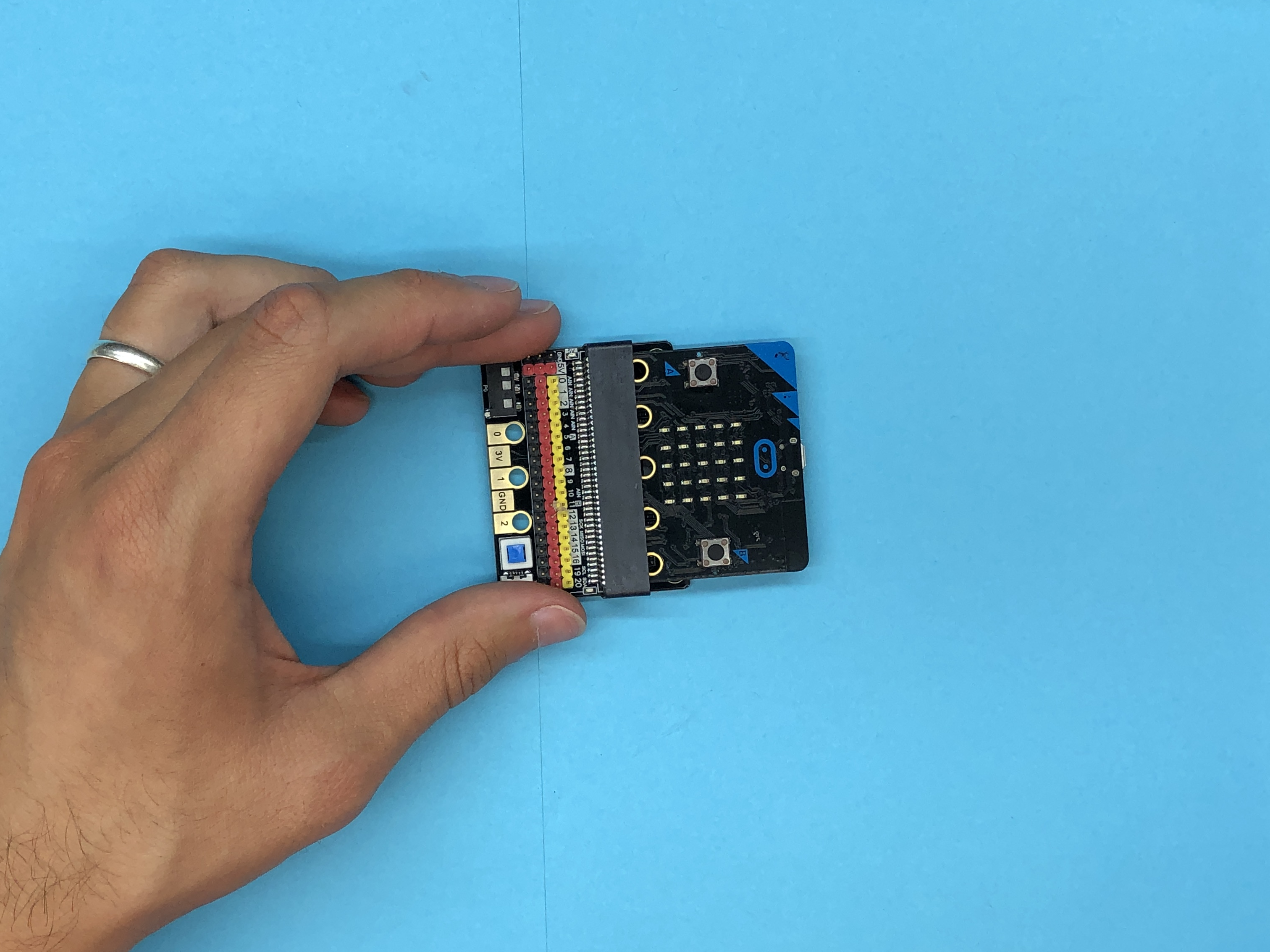
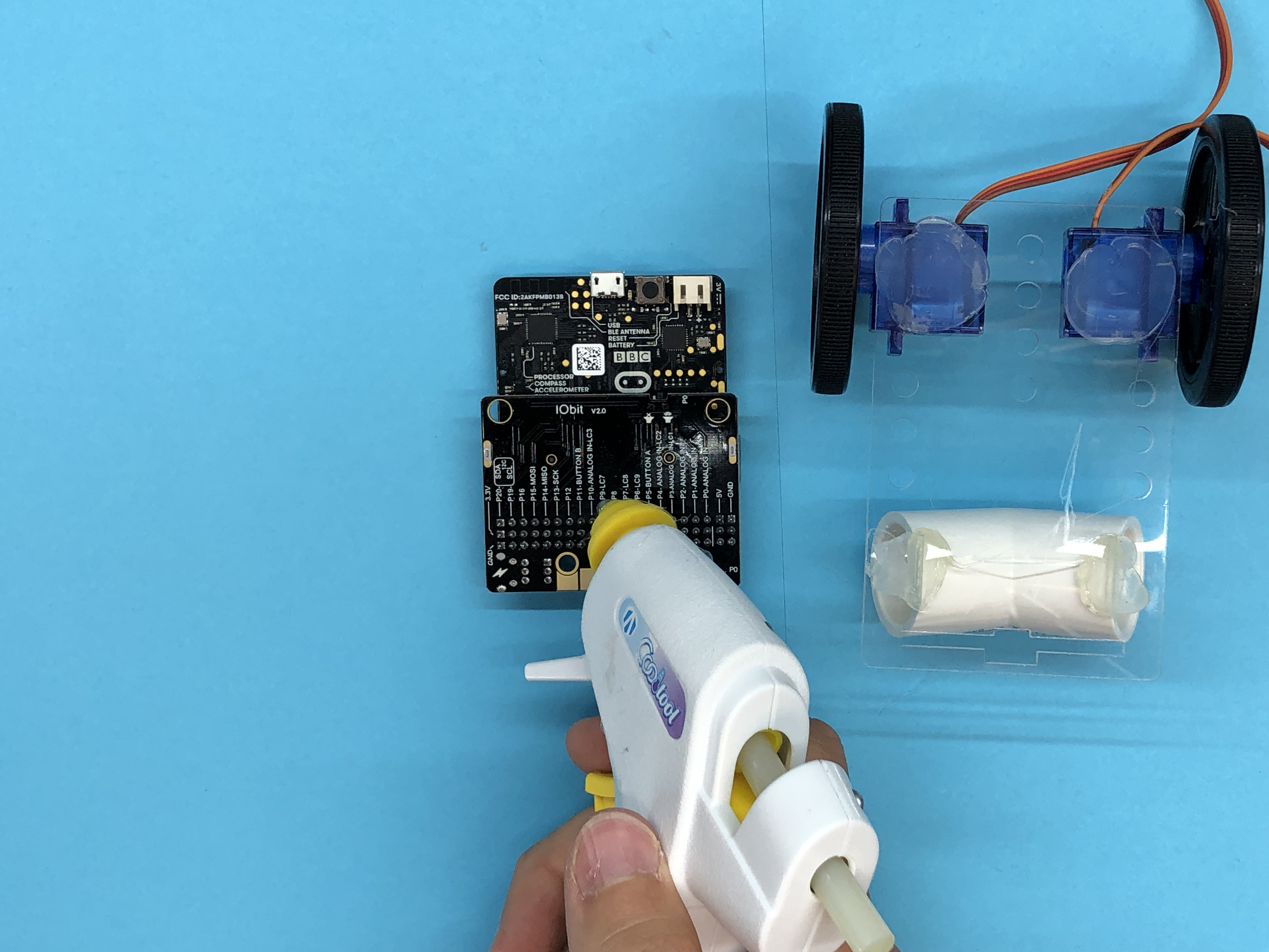
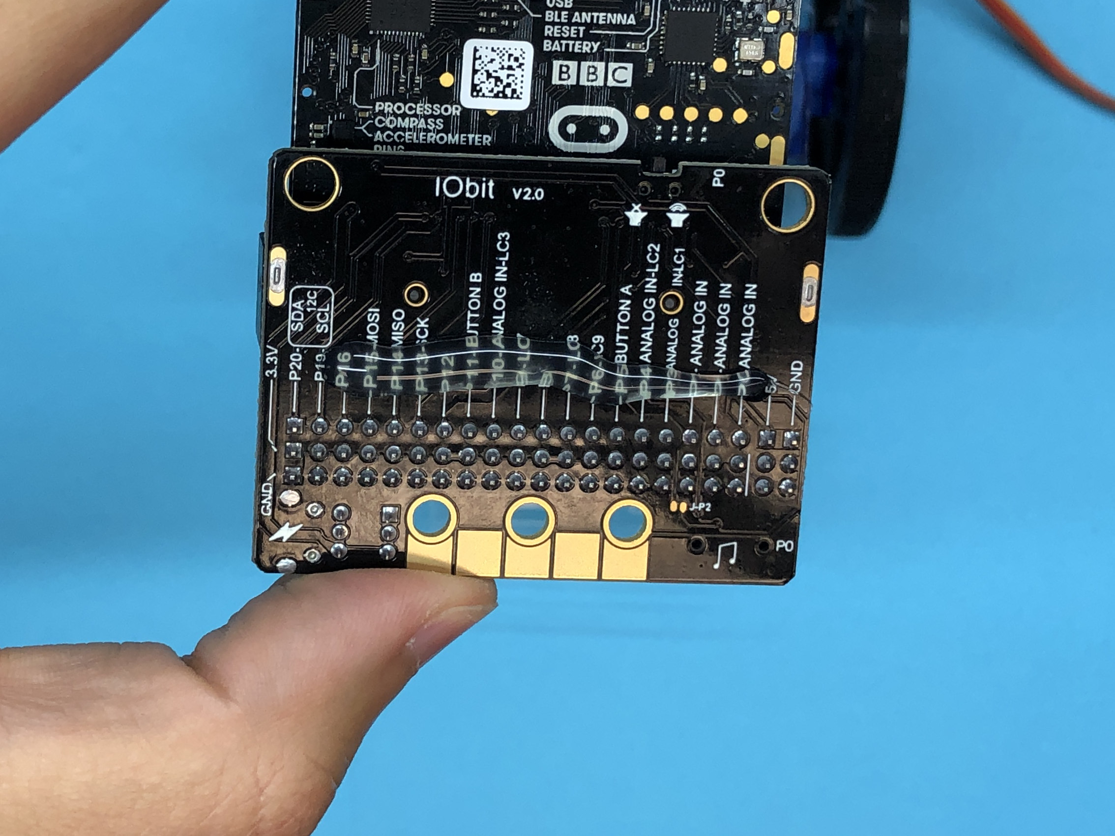
Connect your Micro:bit and breakout board. Add glue to your breakout board, the place the board on to of your mounting plate.
Splicing Battery Connecter
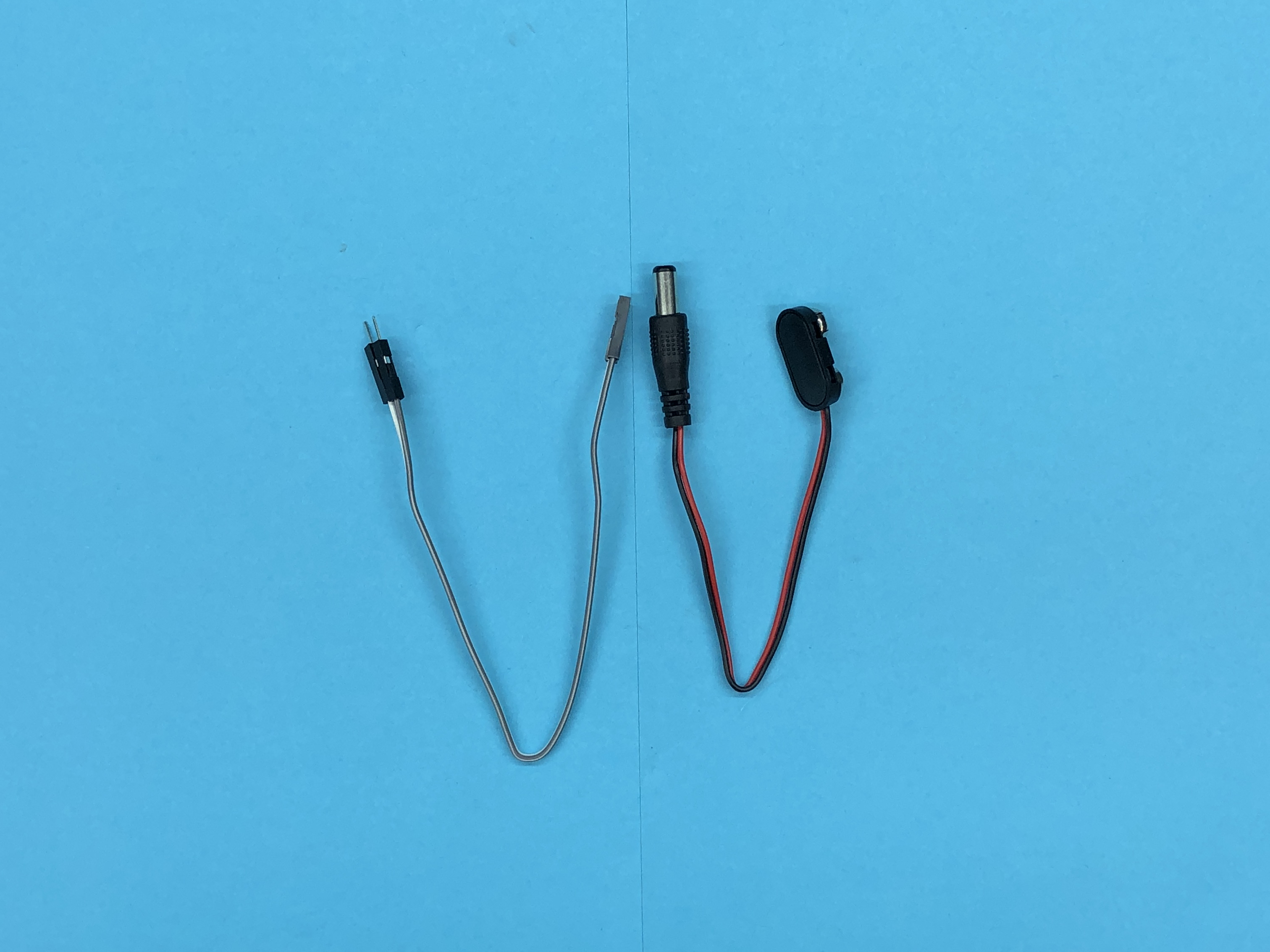
Get your 9v batter connector and your male to female jumper wires. (The colors of your jumper wires may be different, and that is ok!)
Splicing Step A: Cut you the female end of your jumper wires with about two inches remaining. (You no longer need the male ends)
Splicing Step B: Cut your 9v connector in half.
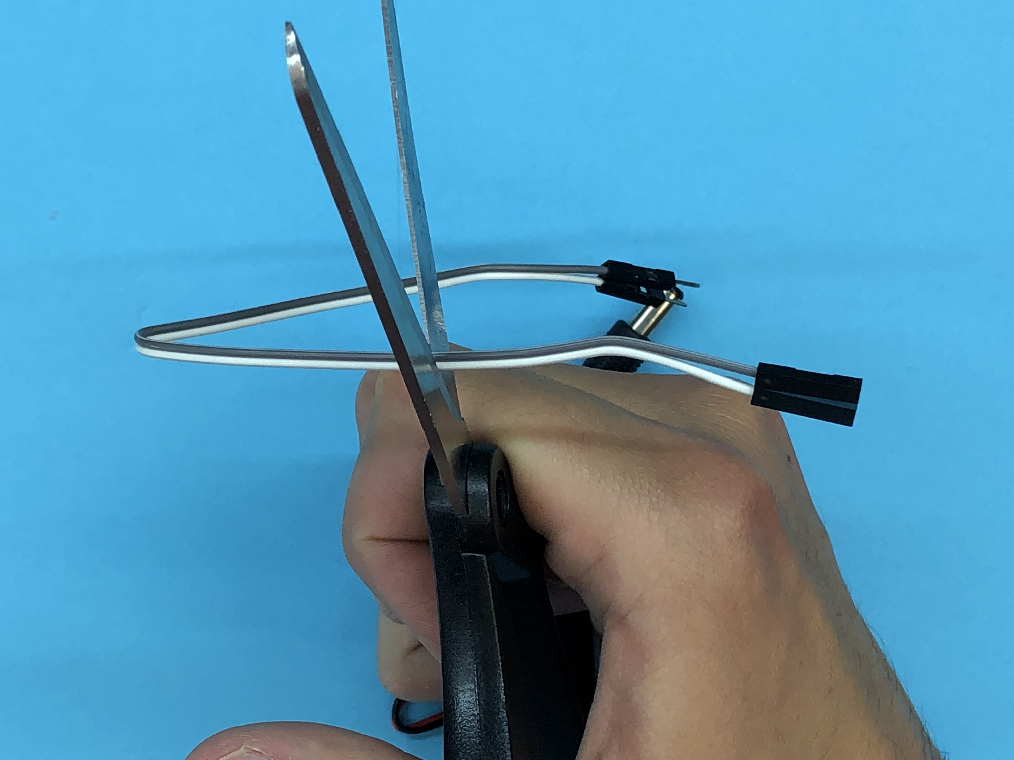
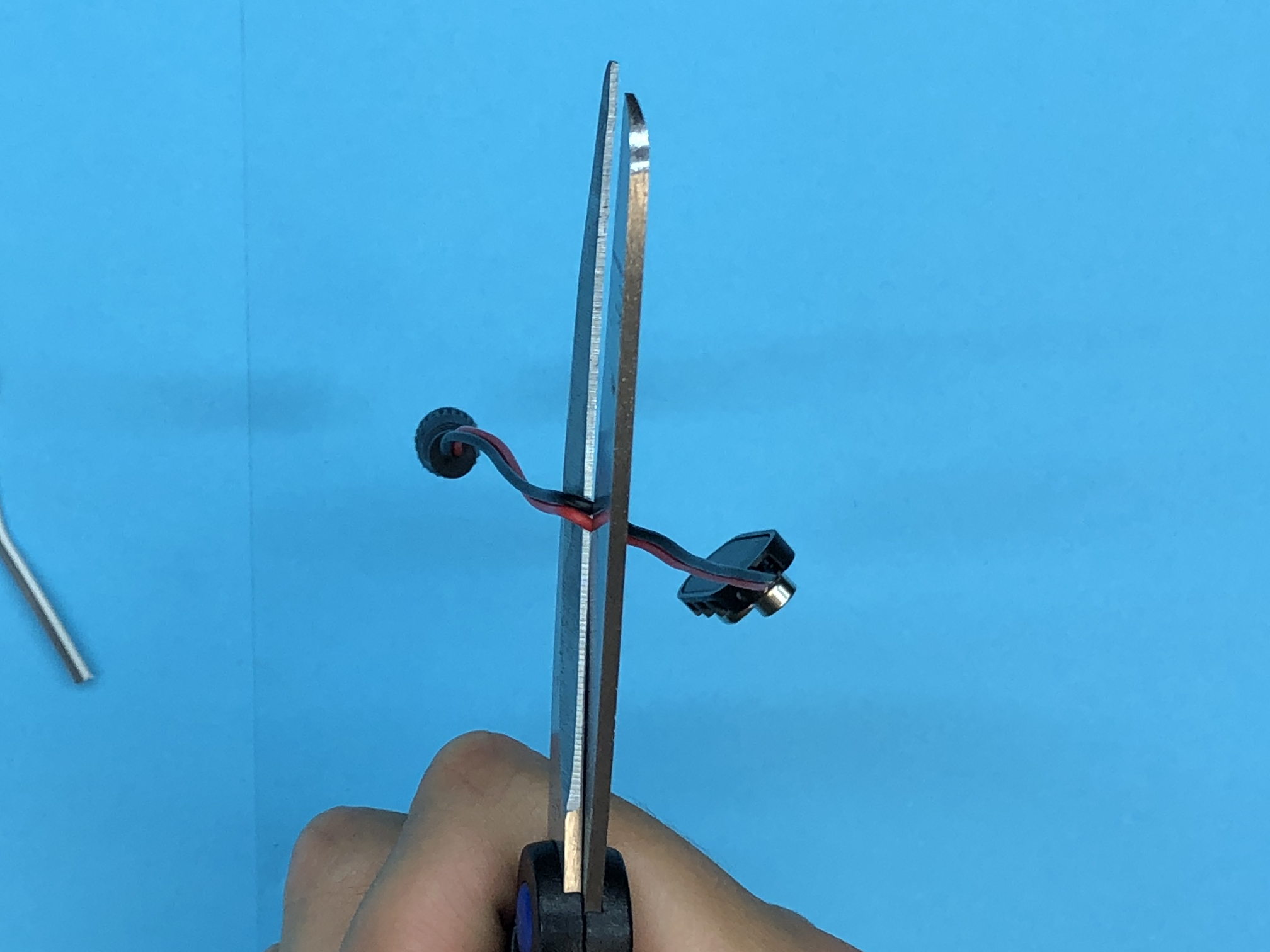
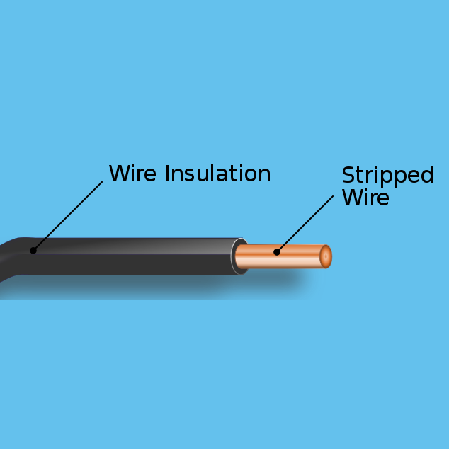
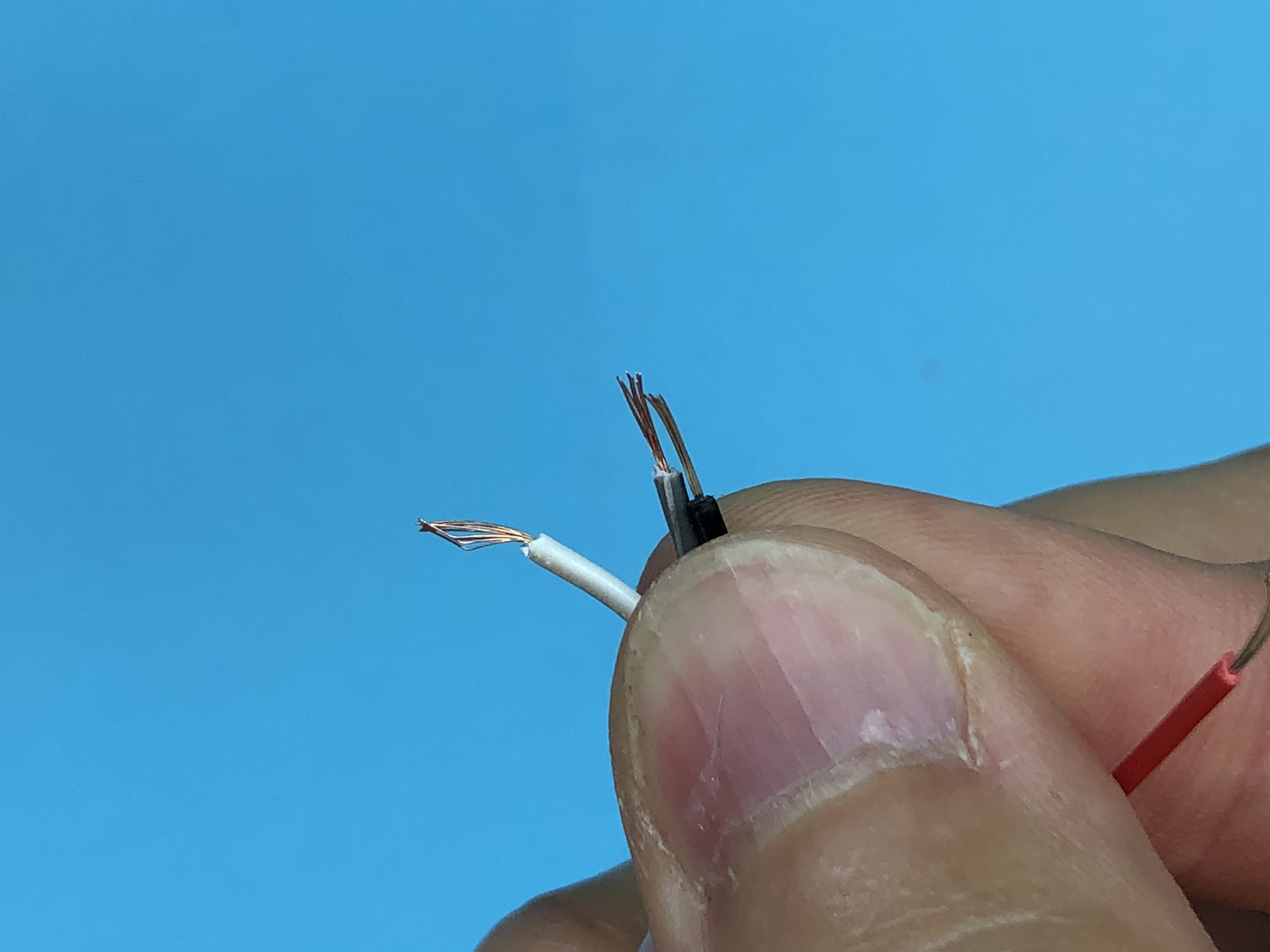
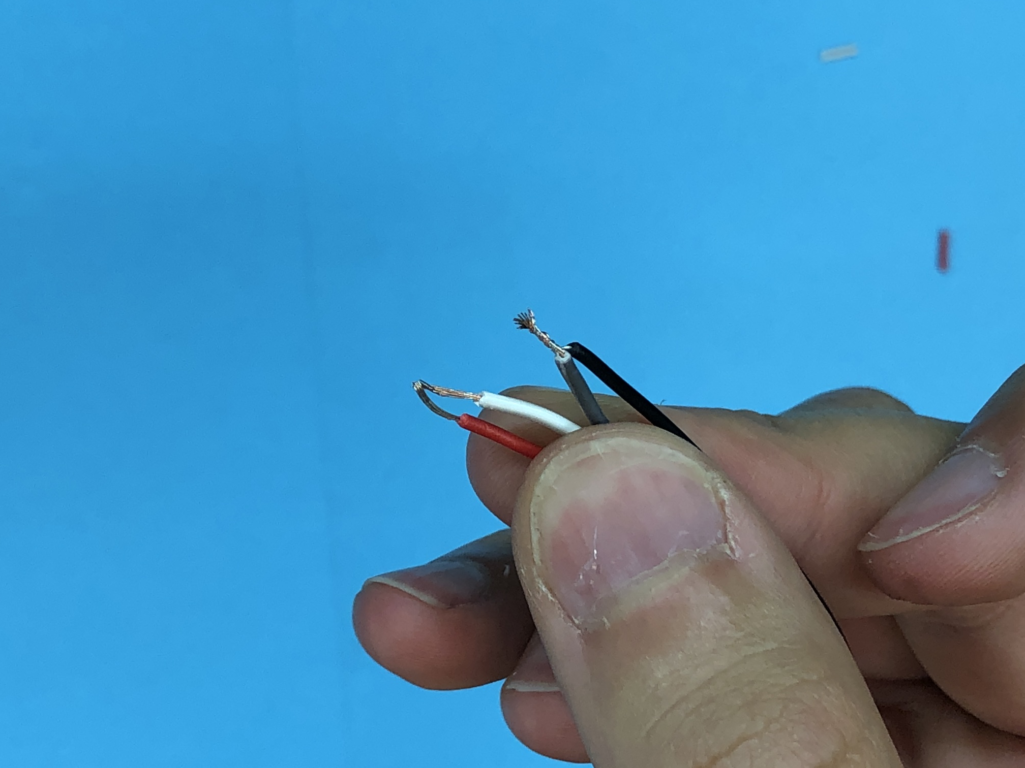
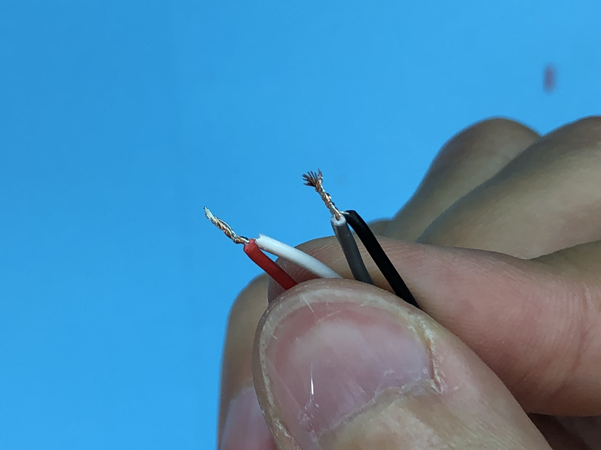
Stripping Wire
.png)
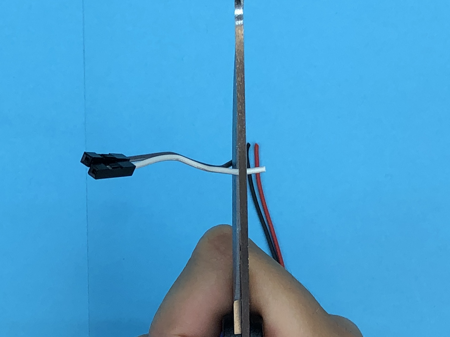
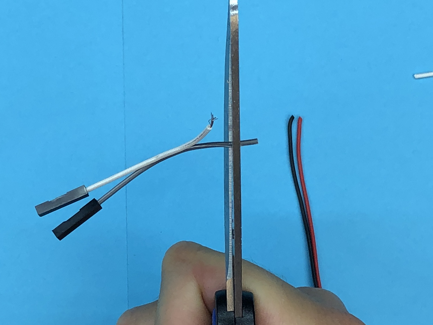

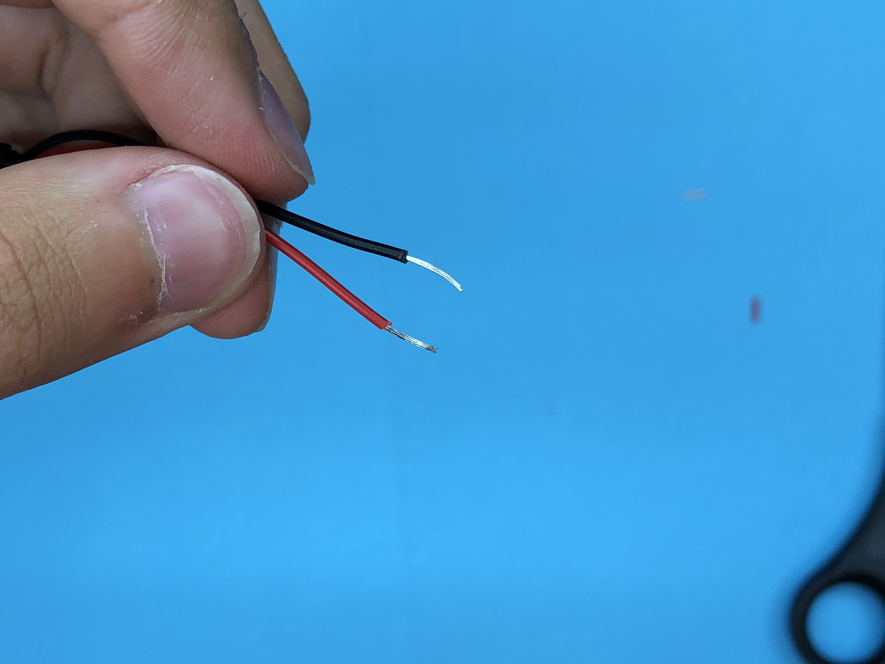
Splicing Step C: Delicately use scissors to remove the insulator and expose about a quarter inch of stripped wire on all 4 cut ends
Splicing Wire
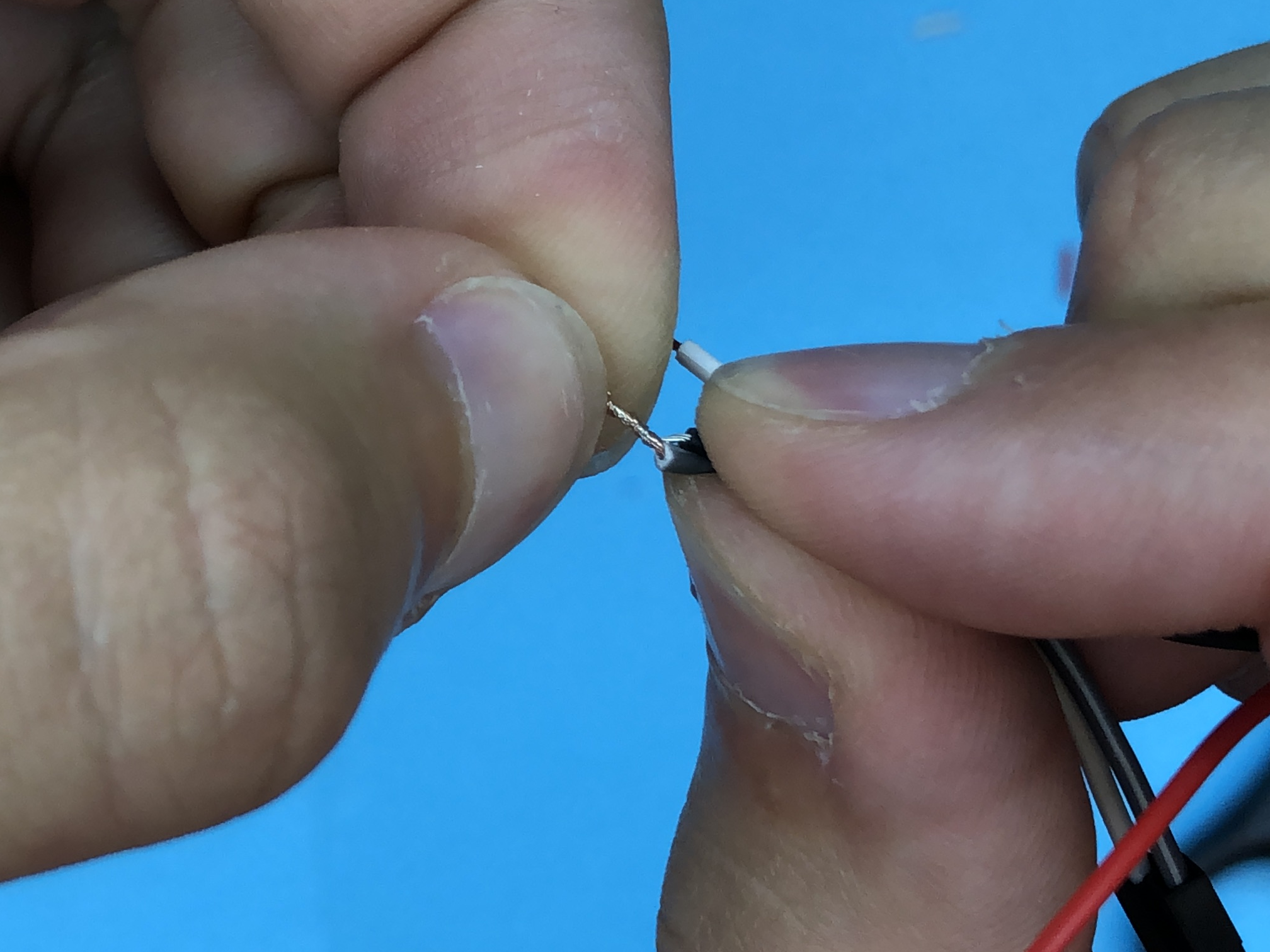
Splicing Step D: Take one end of your stripped jumper wire and twist it together with one end of your stripped 9v connector. Repeat the process for your other two wires. (I put the dark colors together and light colors together)
Insulating Wire
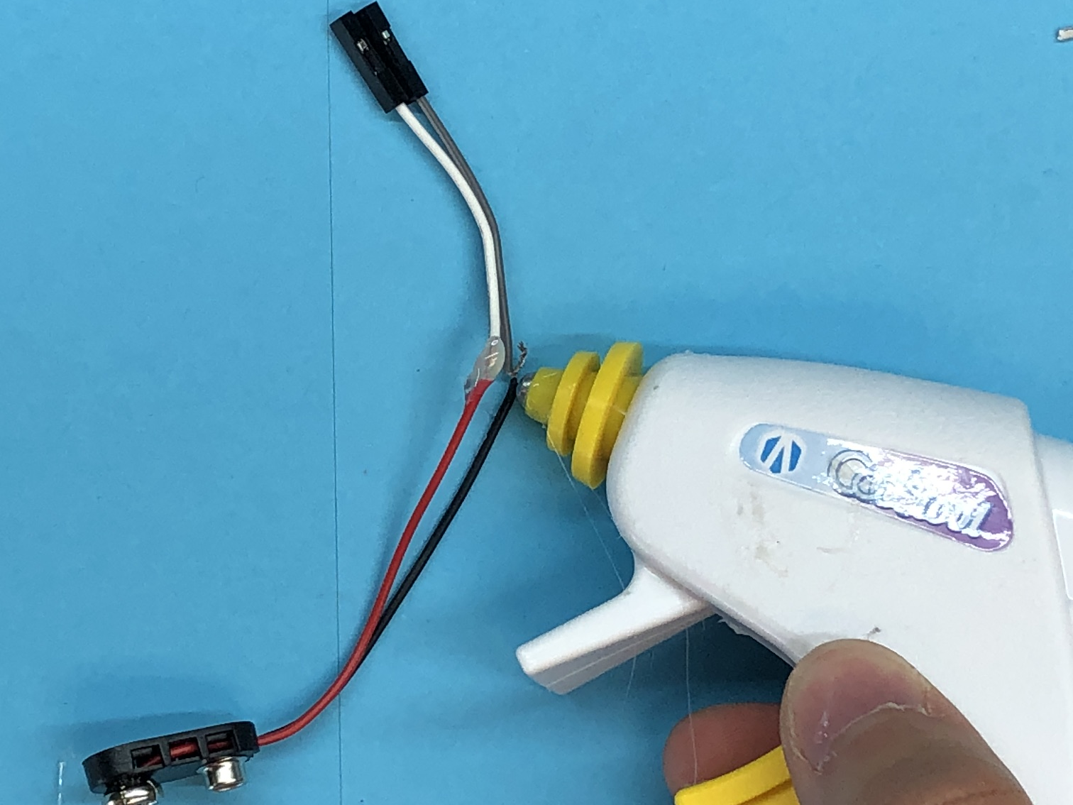
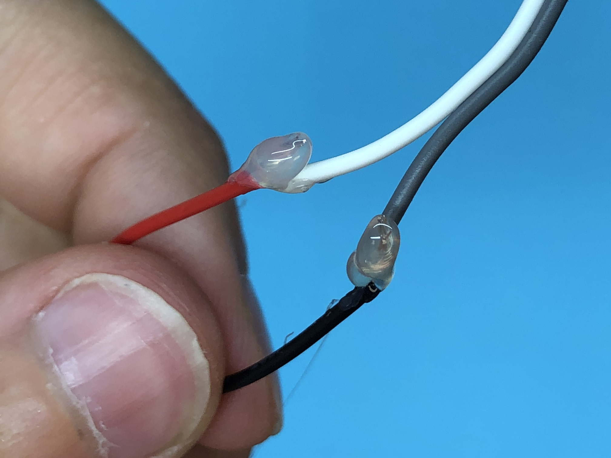
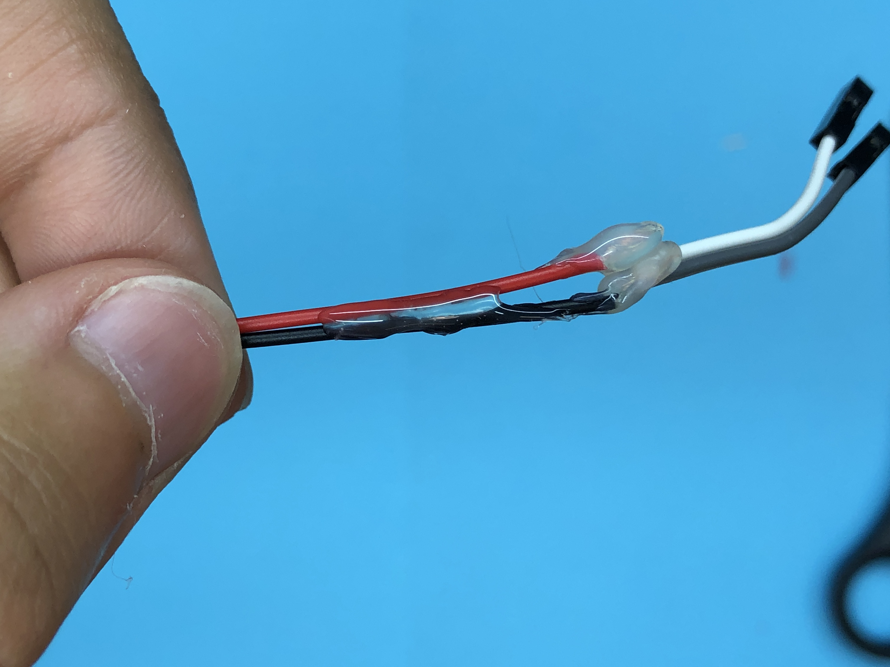
Splicing Step E: Use your hot glue gun to insulate your wires. Make sure the stripped wires cannot touch each other! If the stripped wires touch while electricity flows through them, they will short out, which can be dangerous to both you and your electronics.
Adding Batteries
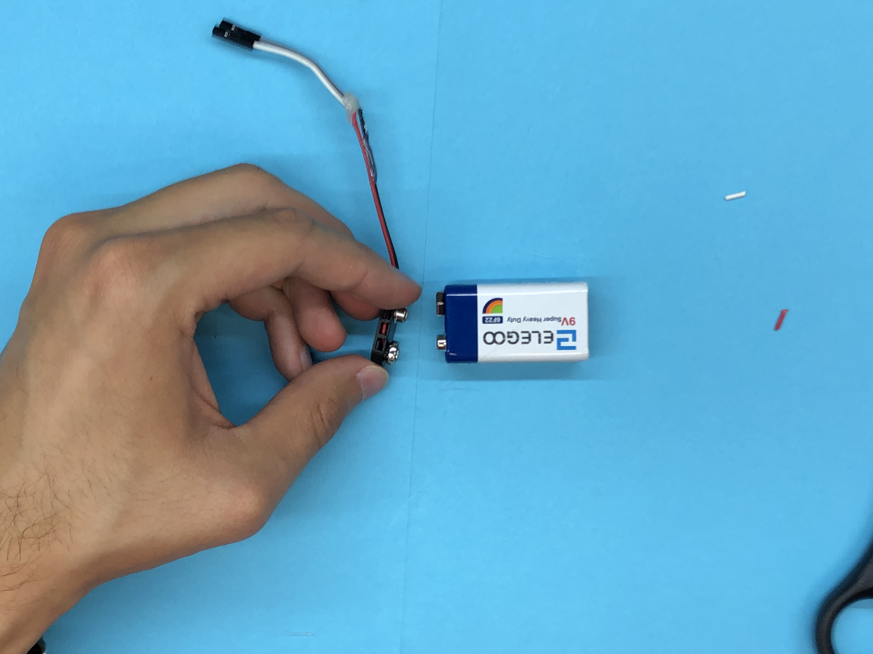
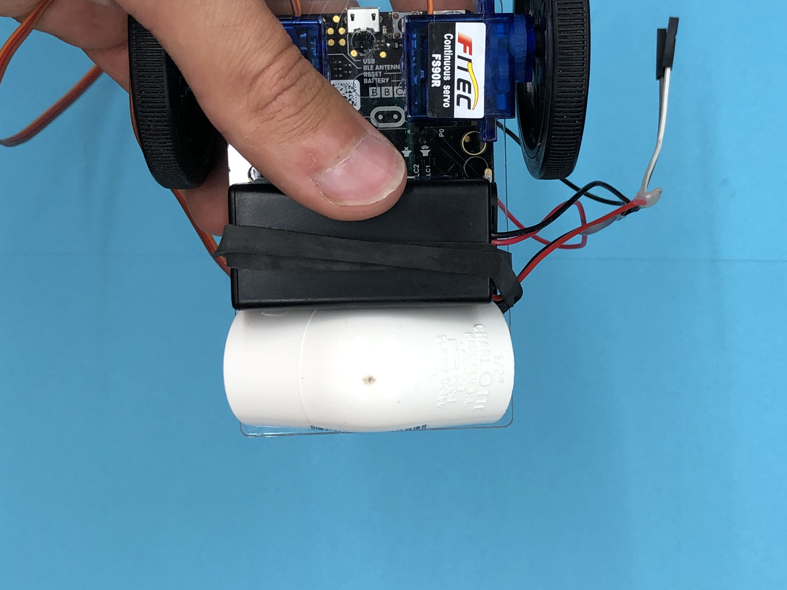
Add the batteries to the bottom of your mounting plate. Use the rubber band to hold them in place.
Plug in Battery Pack
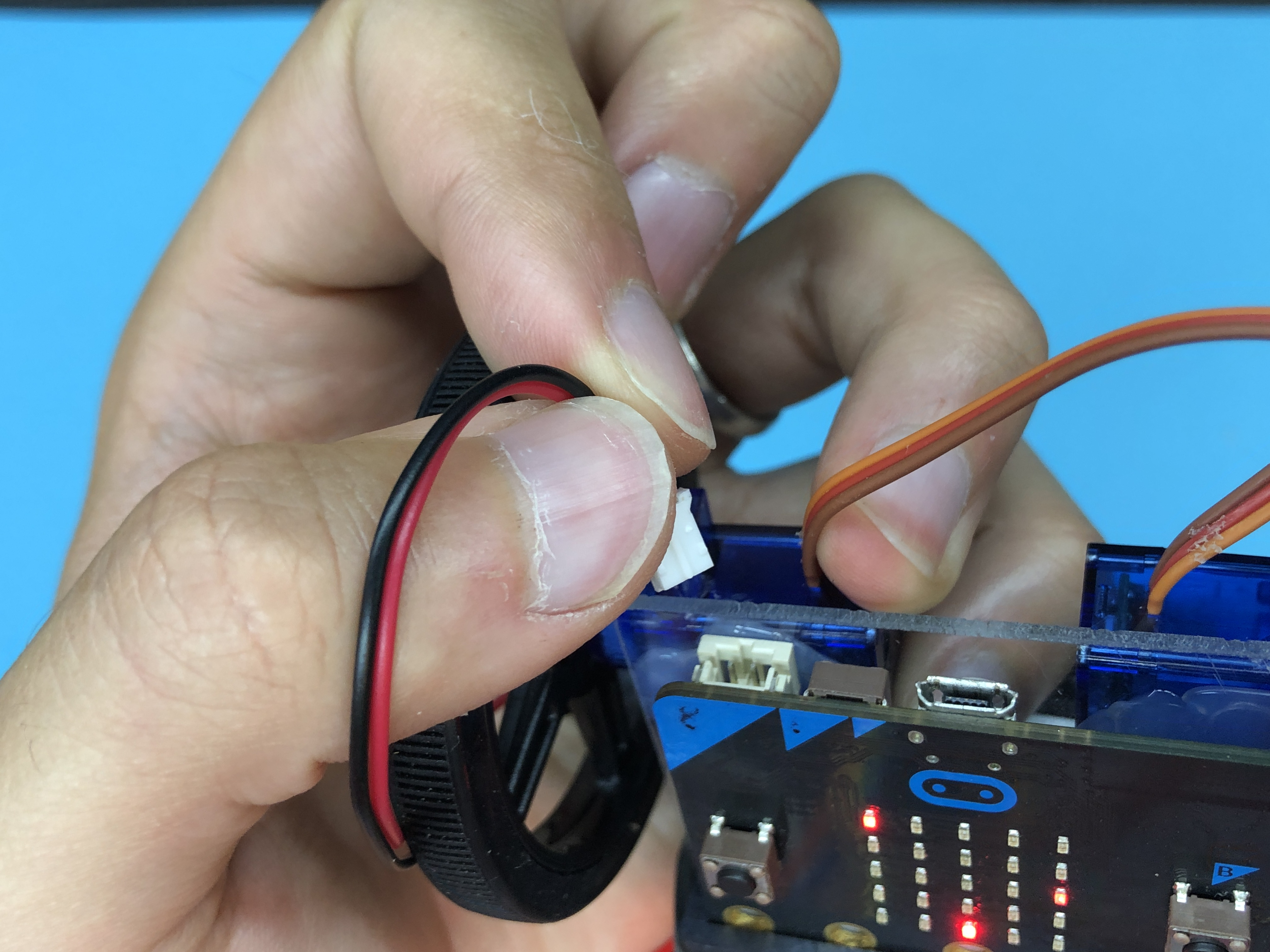
Plug the battery pack into the top of your Micro:Bit.
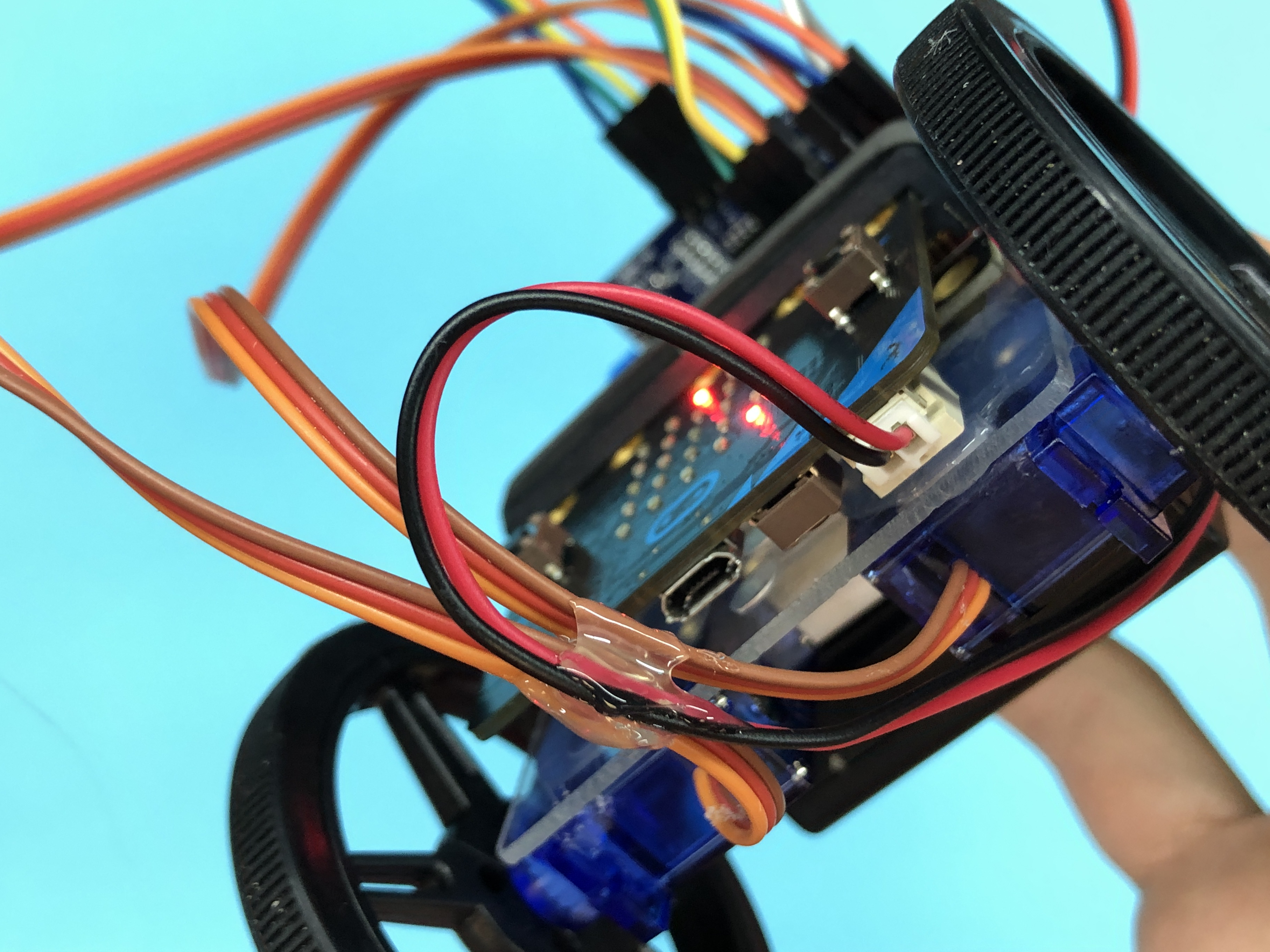
Plug in 9v
.png)
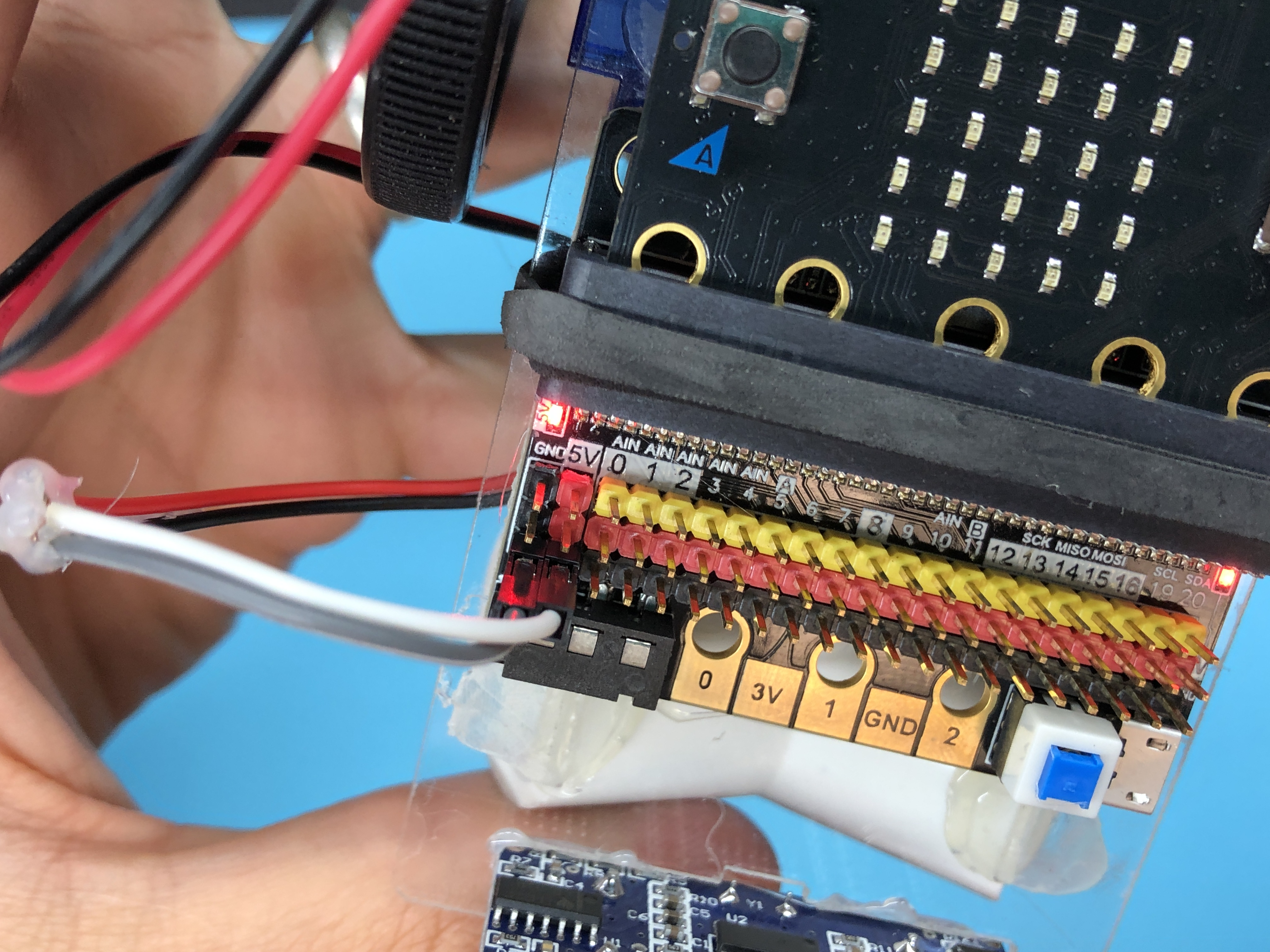
Take the female ends of your spliced 9v connector and plug them into your breakout board as pictured above. The red wire (Positive) needs to connect to the red pin and the black wire (Ground) needs to connect to the black pin.
Add Sonar Sensor
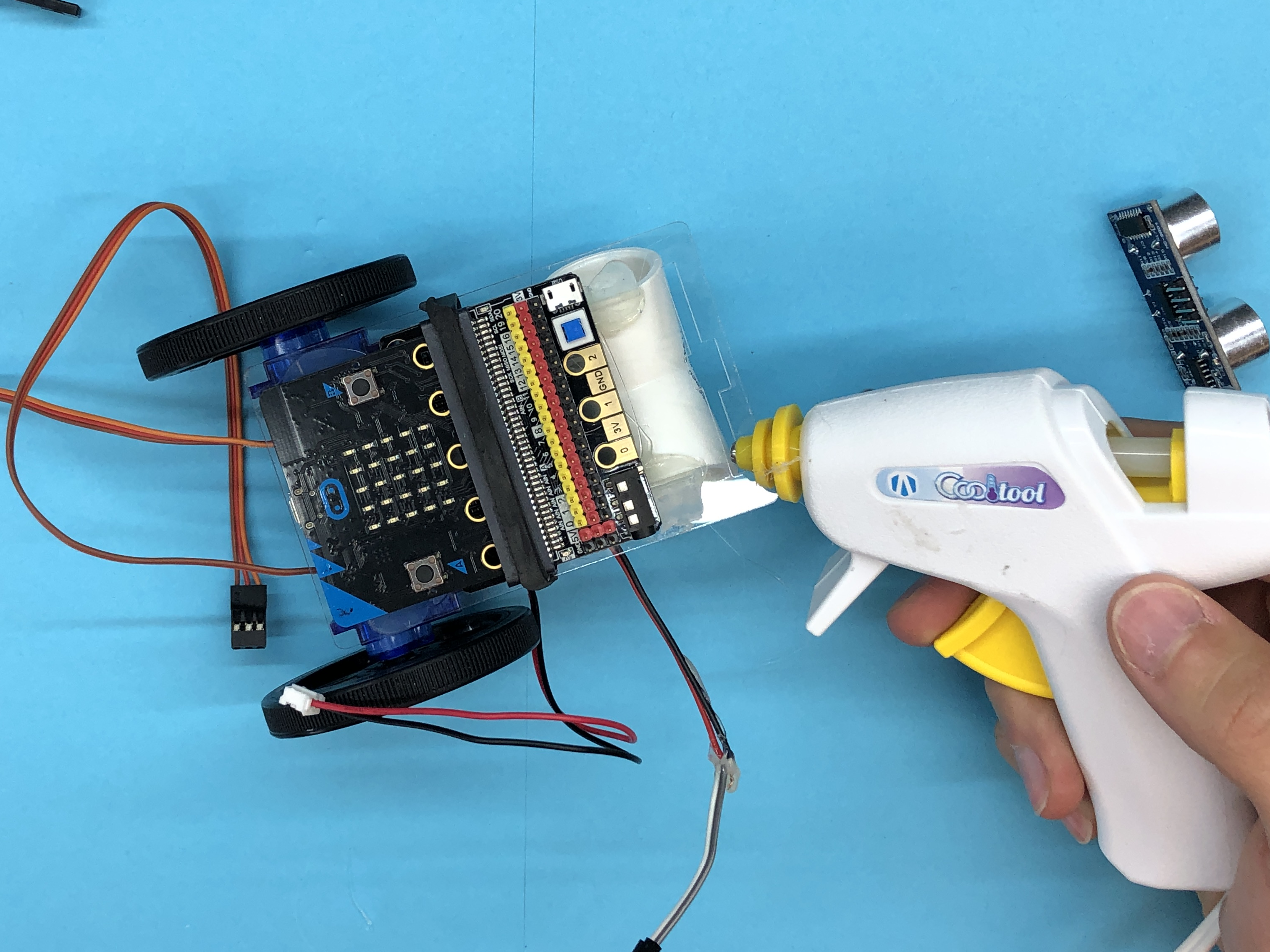
Add glue to the front slot of your mounting plate and insert your ultrasonic sensor.
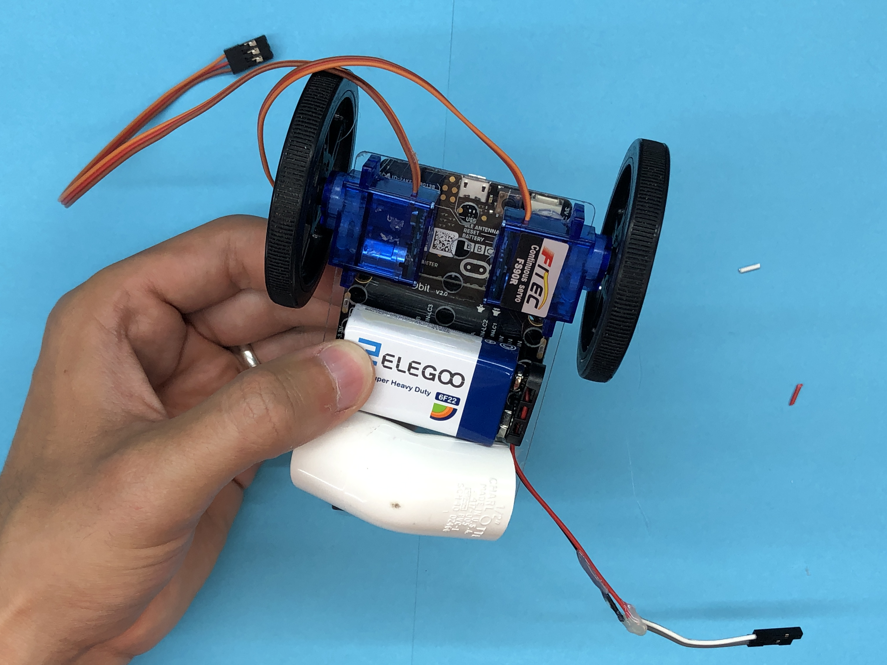
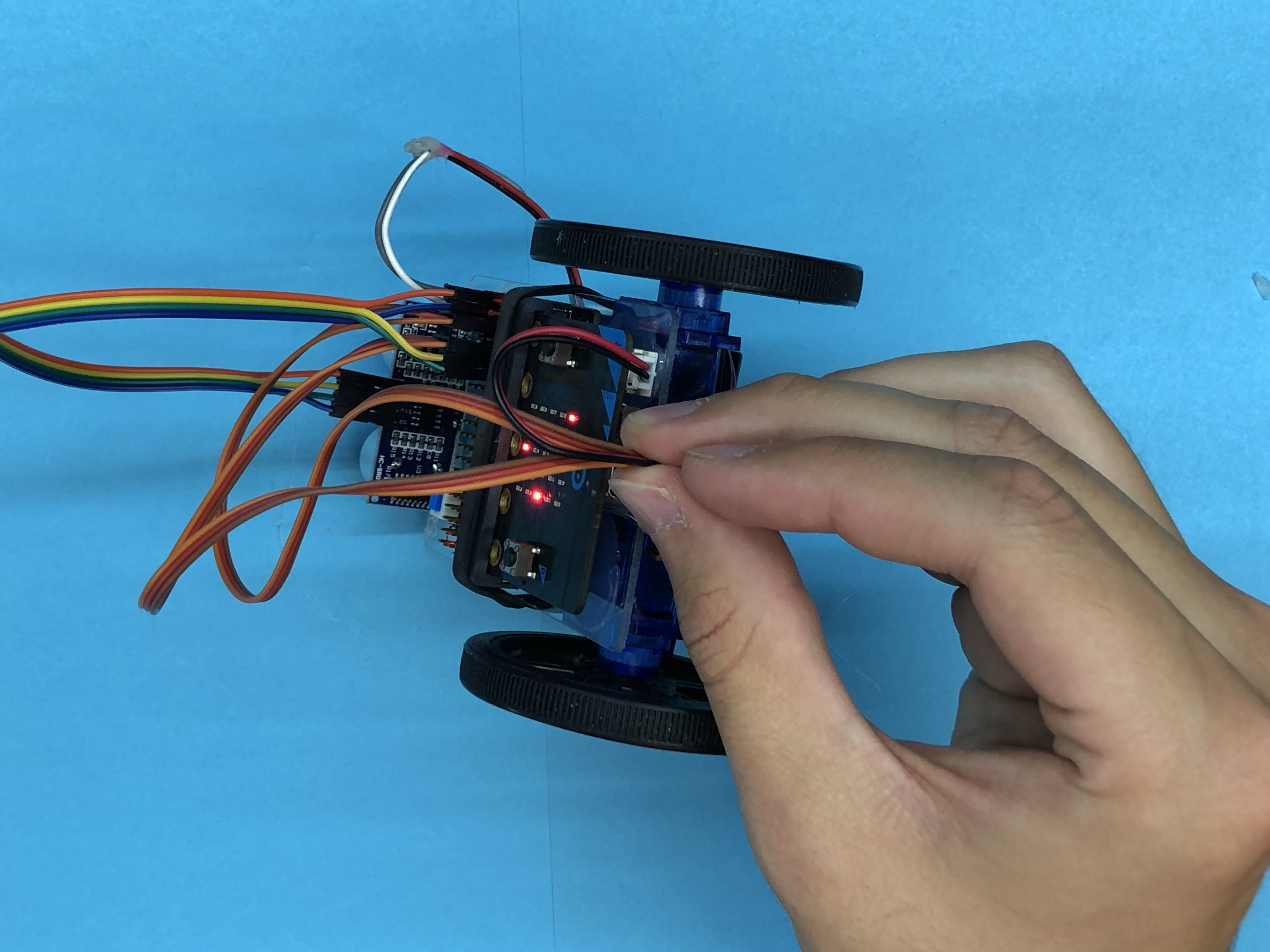
Plug in Servos
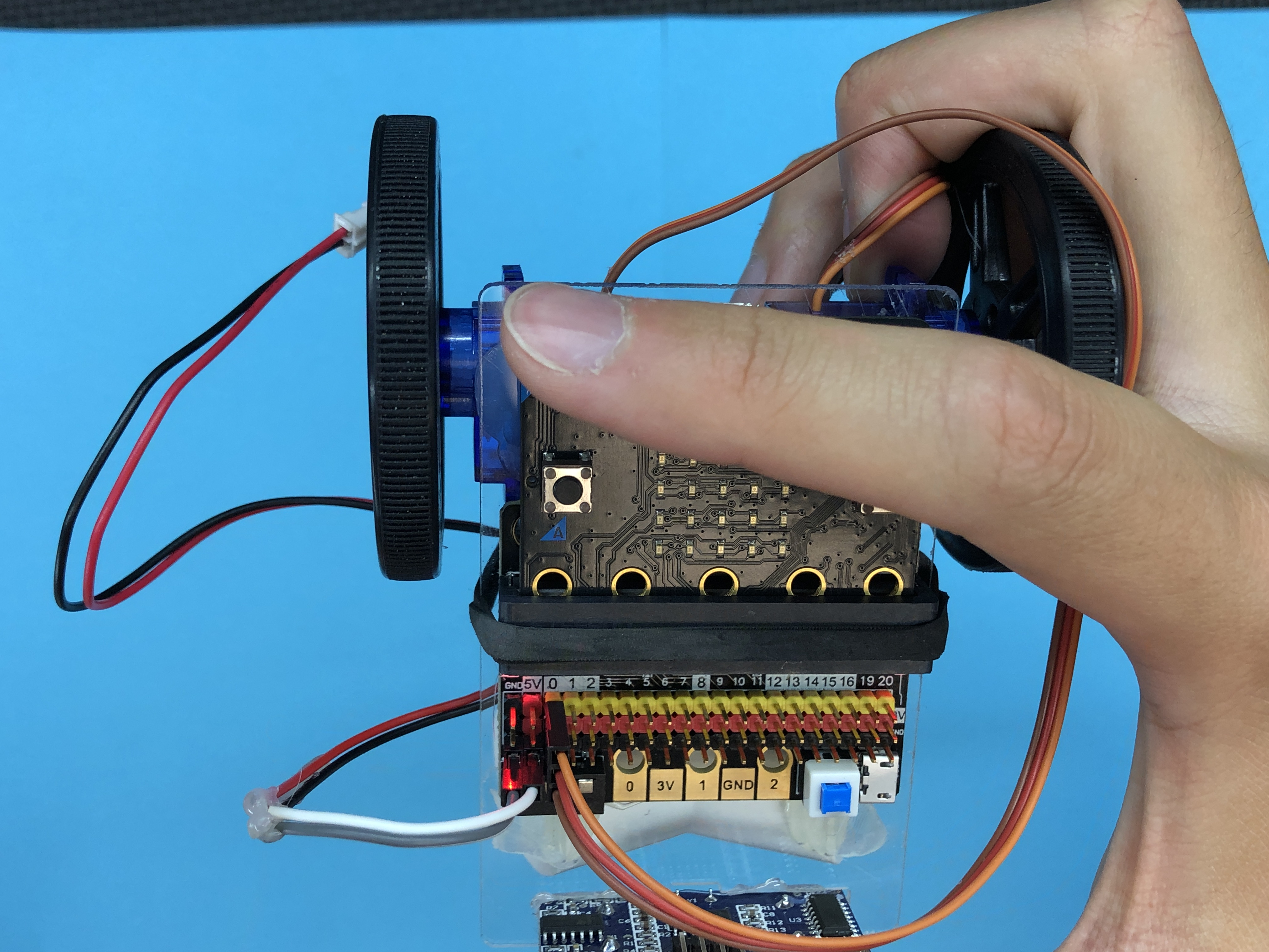
.png)
.png)
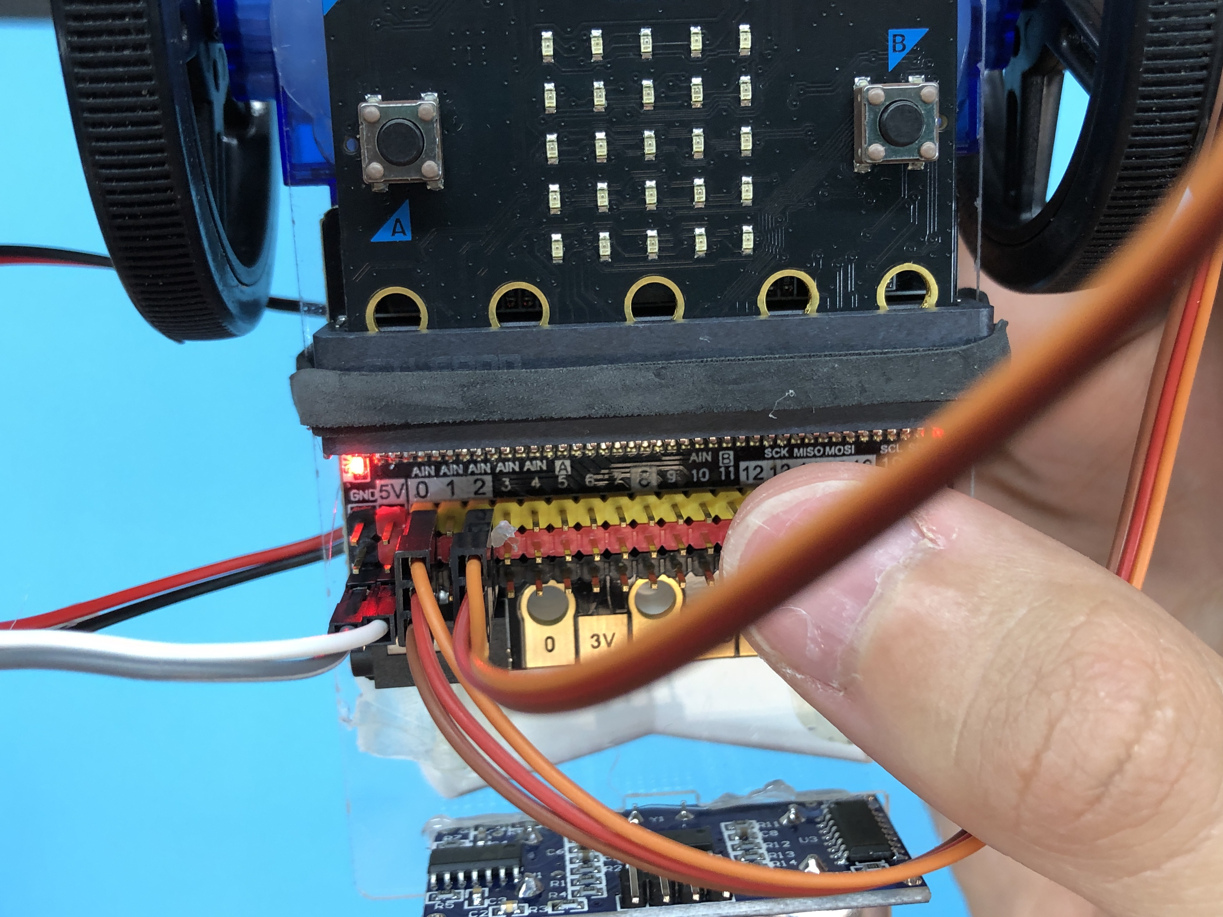
Plug your back left servo into port 0 and your back right servo into port 2.
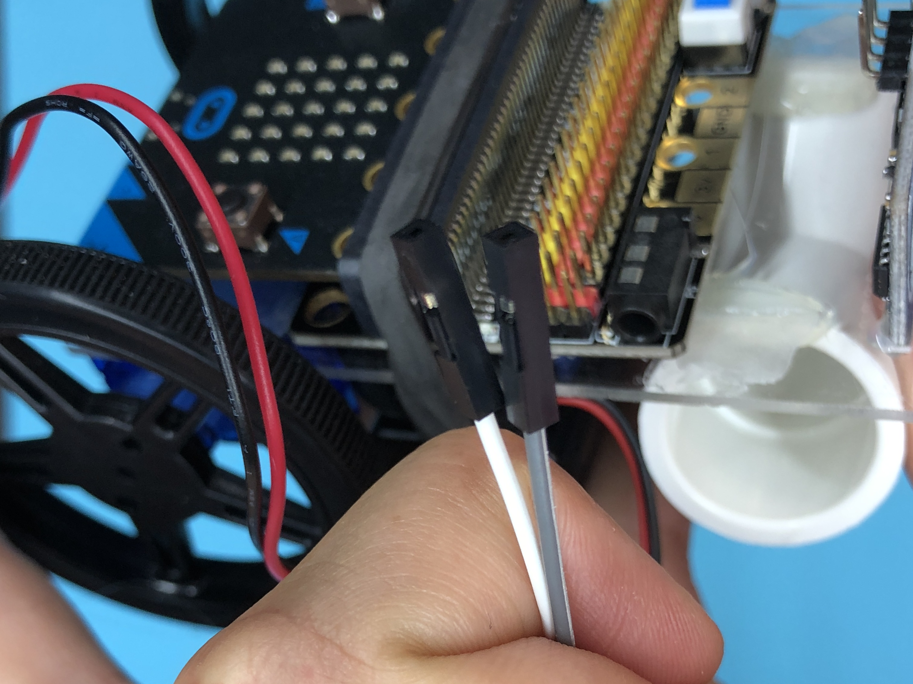
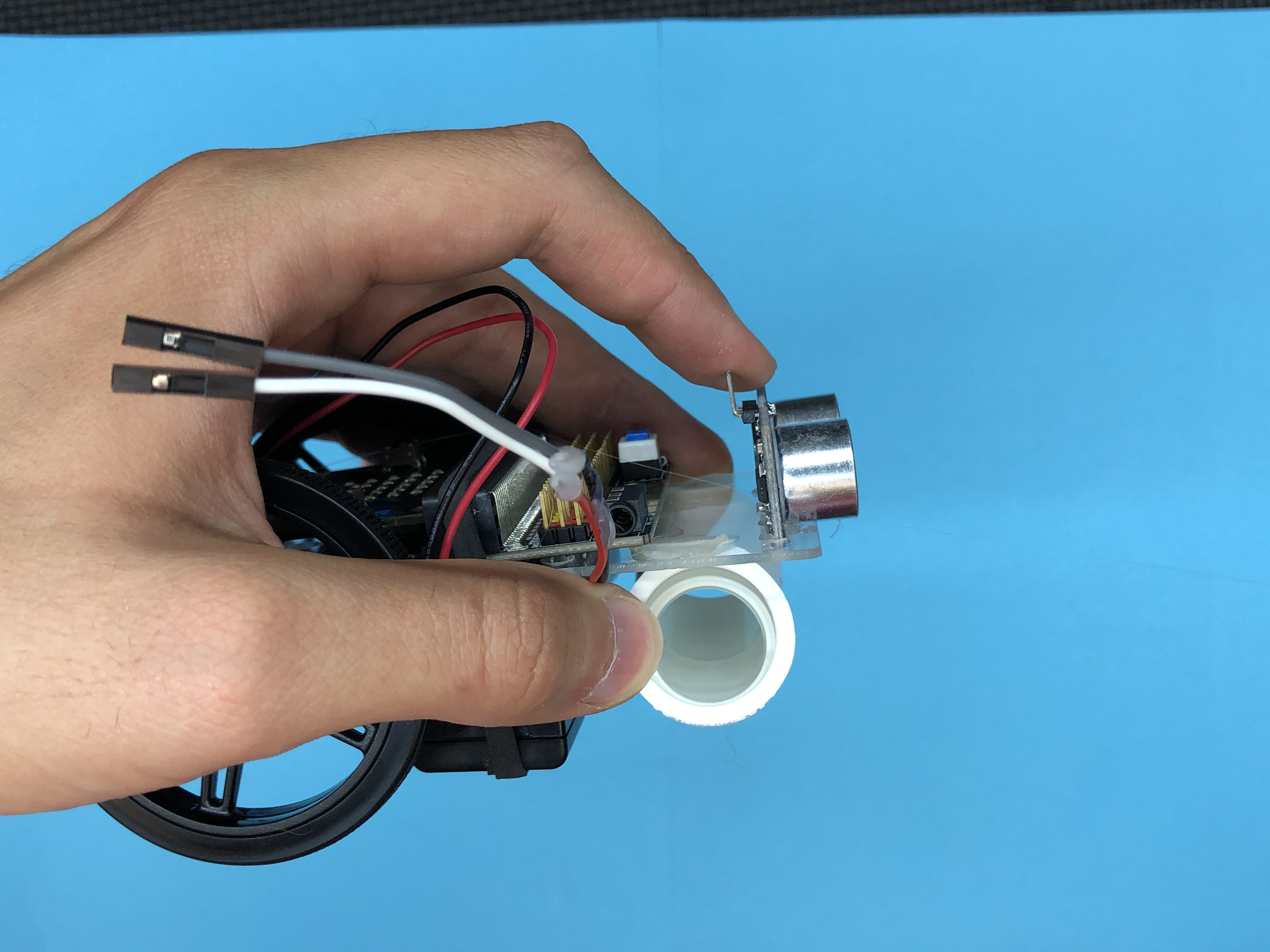
Add Jumper Wires to Sonar
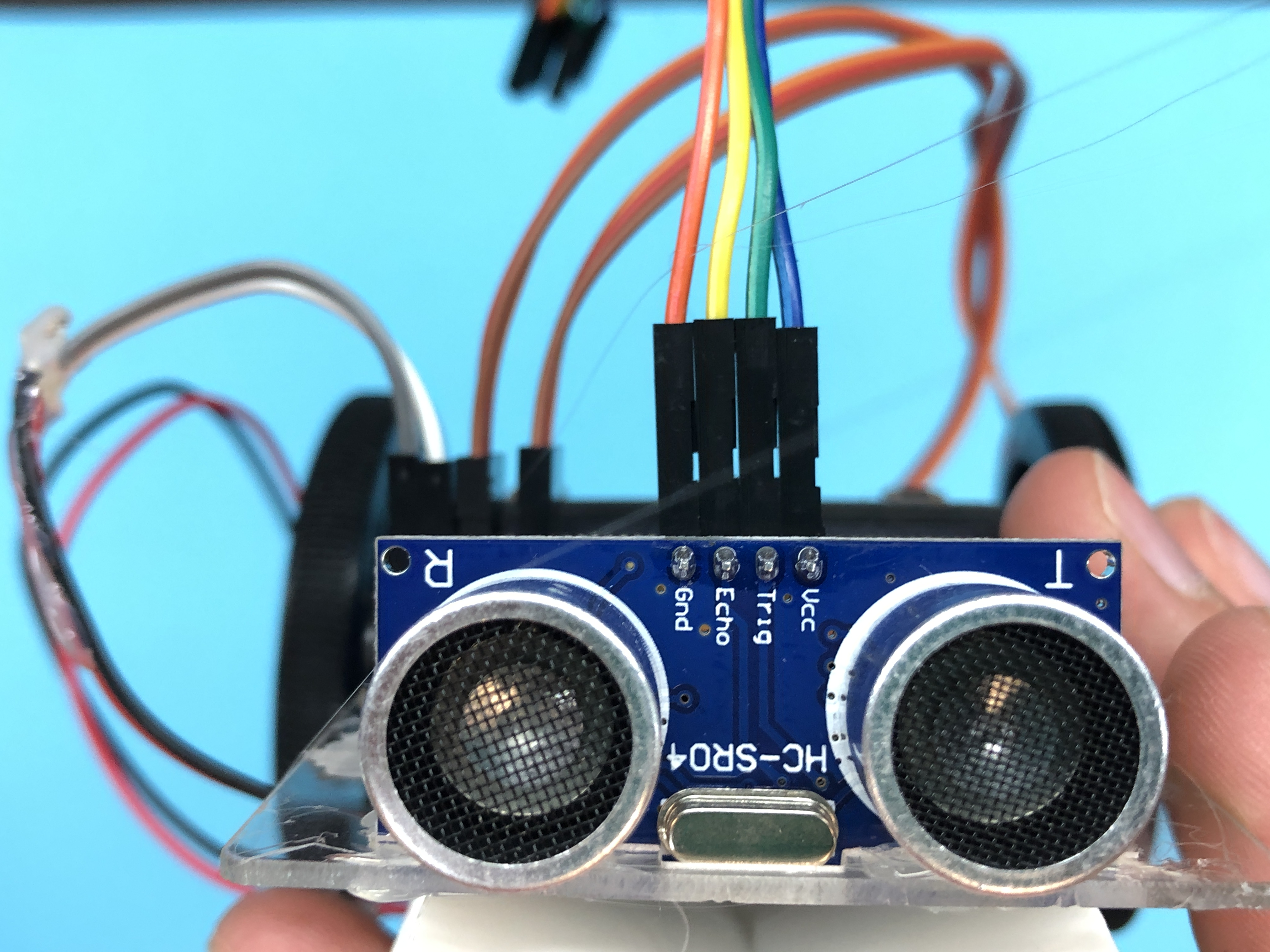
.png)
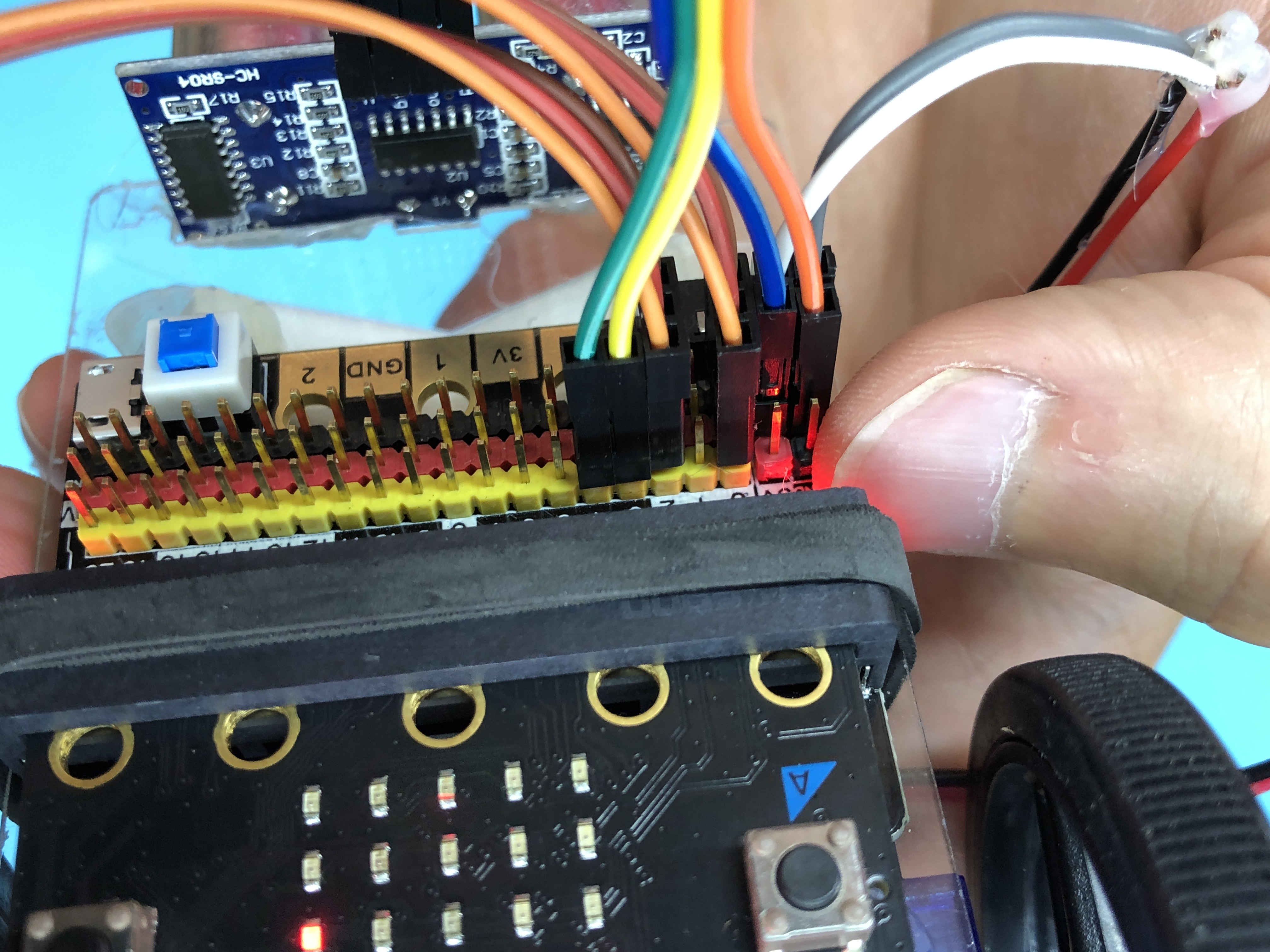
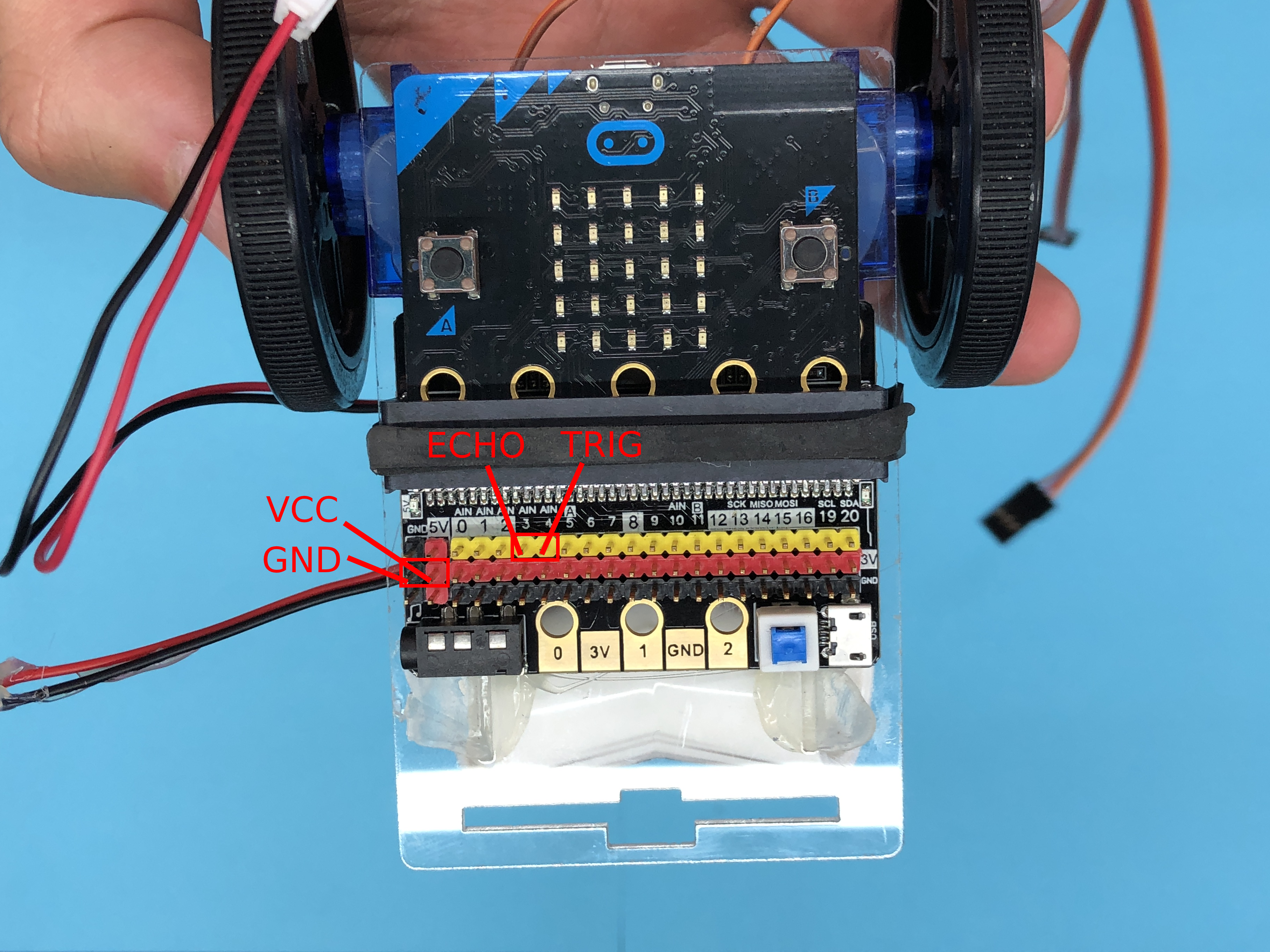
Plug your female to female jumper wires into your sonar, then plug the other ends into the correct pins on your breakout board.
Vcc -> Positive (Next to your red 9v pin)
Gnd -> Ground (Next to your black 9v pin)
Echo -> port 3 (Yellow pin next to the number 3)
Trig -> port 4 (Yellow pin next to the number 4)
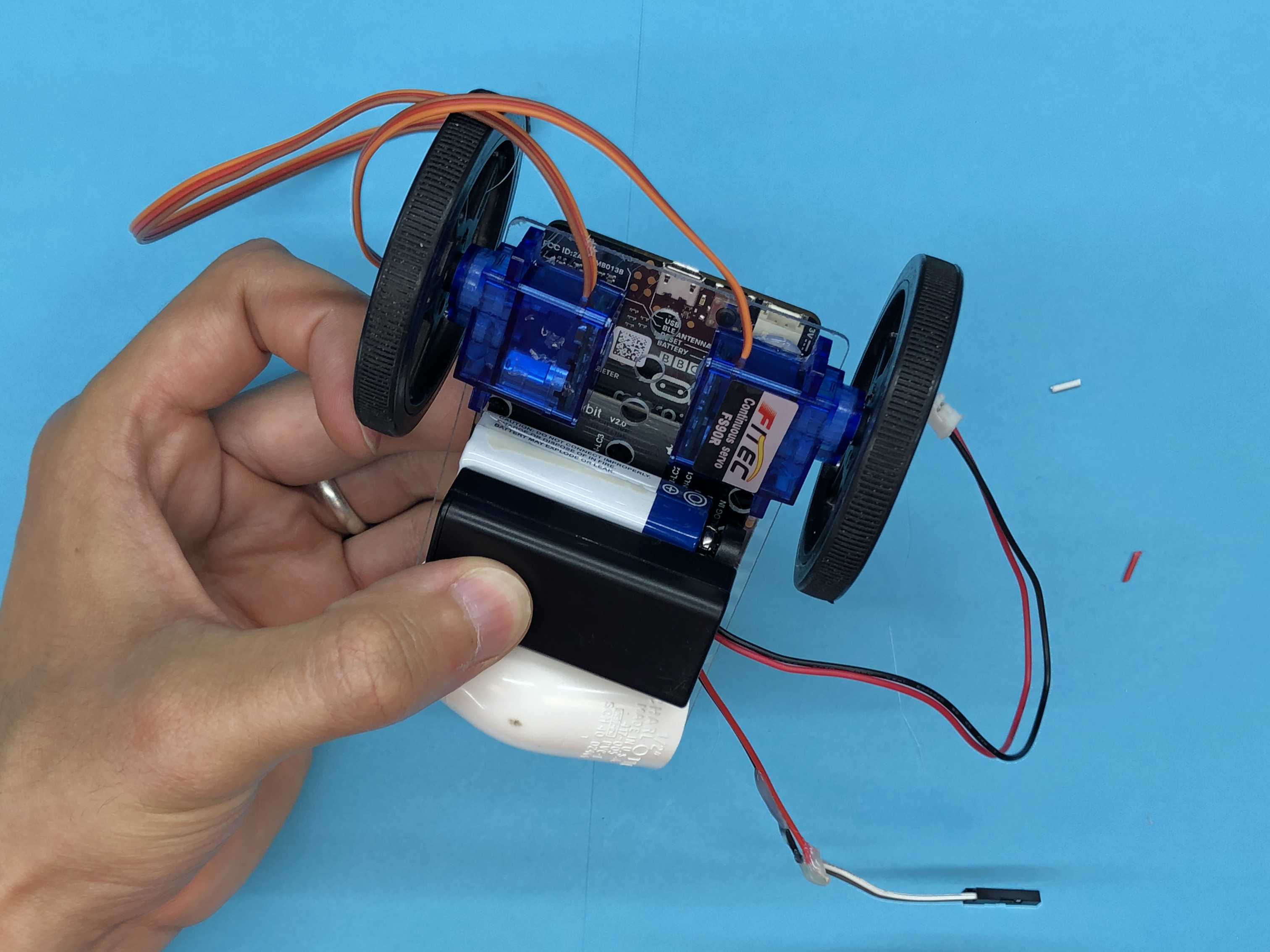
Wire Cleanup
Bunch up all your wires away from the wheels and add some glue to keep them out of the way.
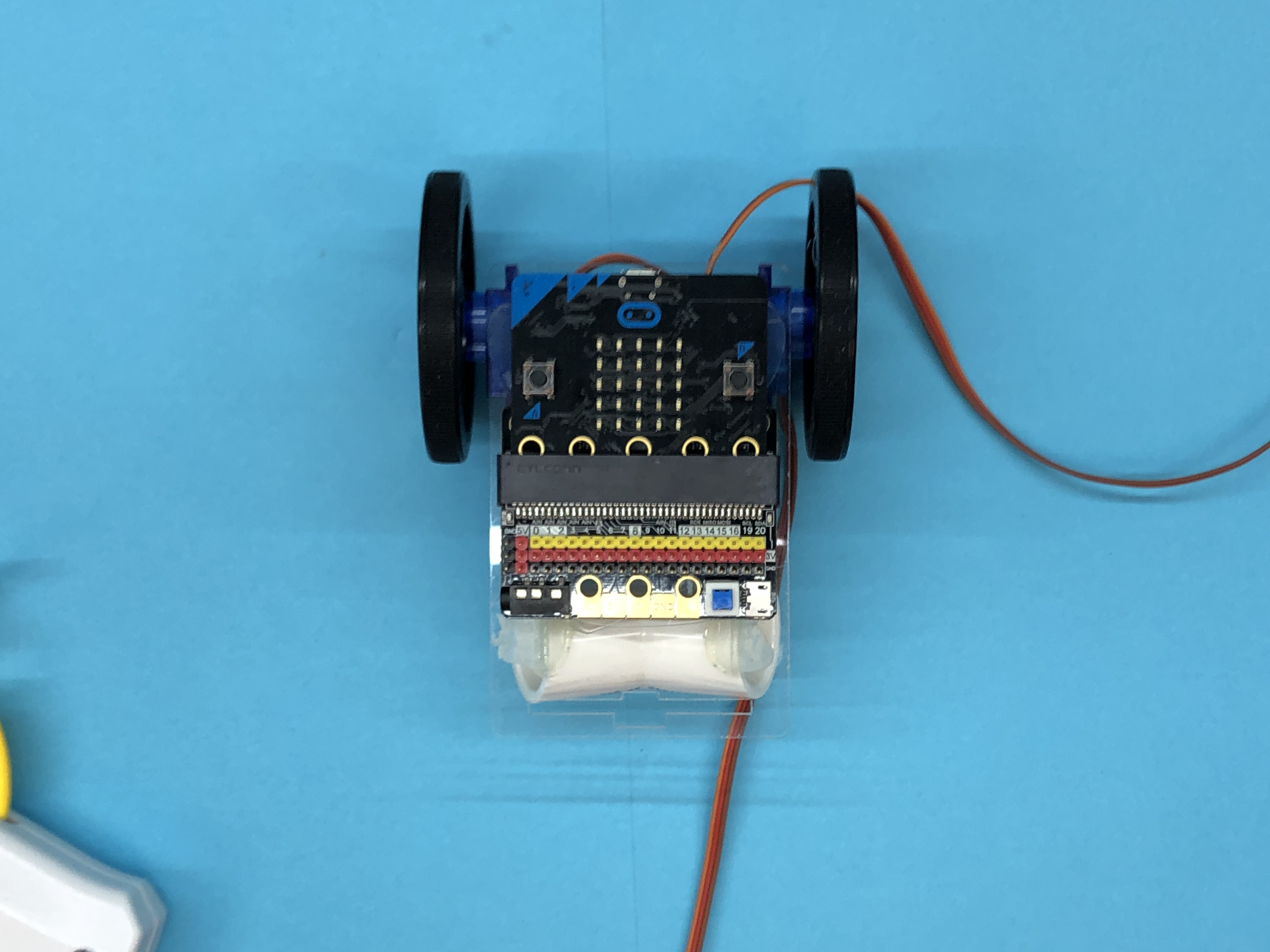
You're Done!

Wow! You're already done! You built a robot! Try out some programs to get it driving!
Here Are Video Instructions If You Prefer That! :)