Micro SD Card Tutorial
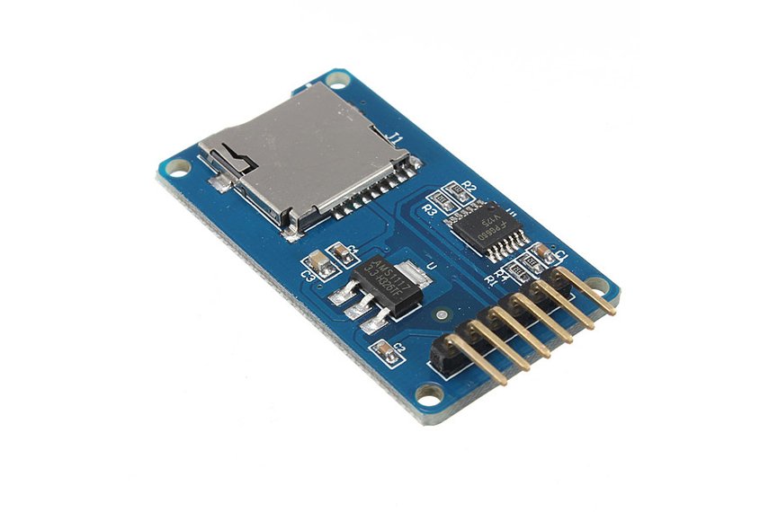
Description
This Micro SD Card is used for transfering data to and from a standard sd card. The pin out is directly compatible with Arduino and also can be used with other microcontrollers. It allow us to add mass storage and data logging to our project.
Features
- Input Voltage: 3.3V/5V
- With all SD SPI Pins out :MOSI, SCK, MISO and CS ,for further connection
- Through programming, you can read and write to the SD card using your arduino
- Make your SD application more easier and simple
- Communicate with Arduino using SPI interface
- Push-pop socket with card slightly over the edge of the PCB so its easy to insert and remove
- 4 mounting holes with 2.2mm diameter
- Only use 4 I/O pins on the Arduino
- Size: 42mm x 25mm x 5mm
Step 1 : Material Planning
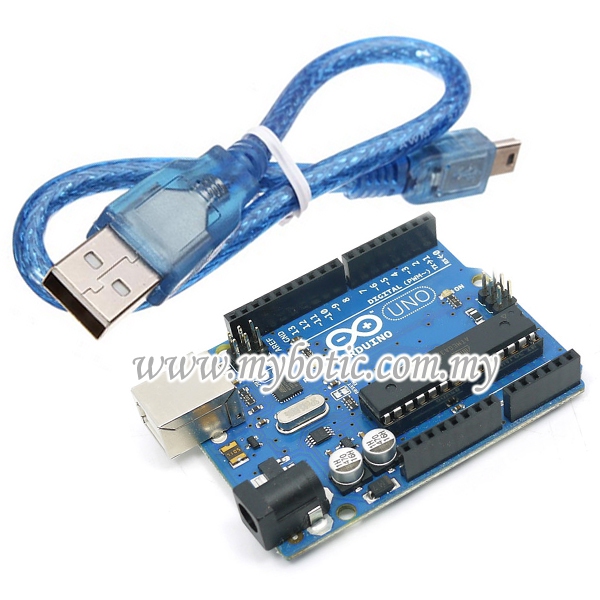
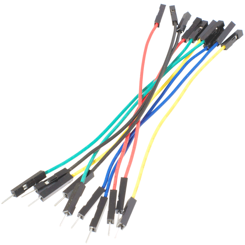
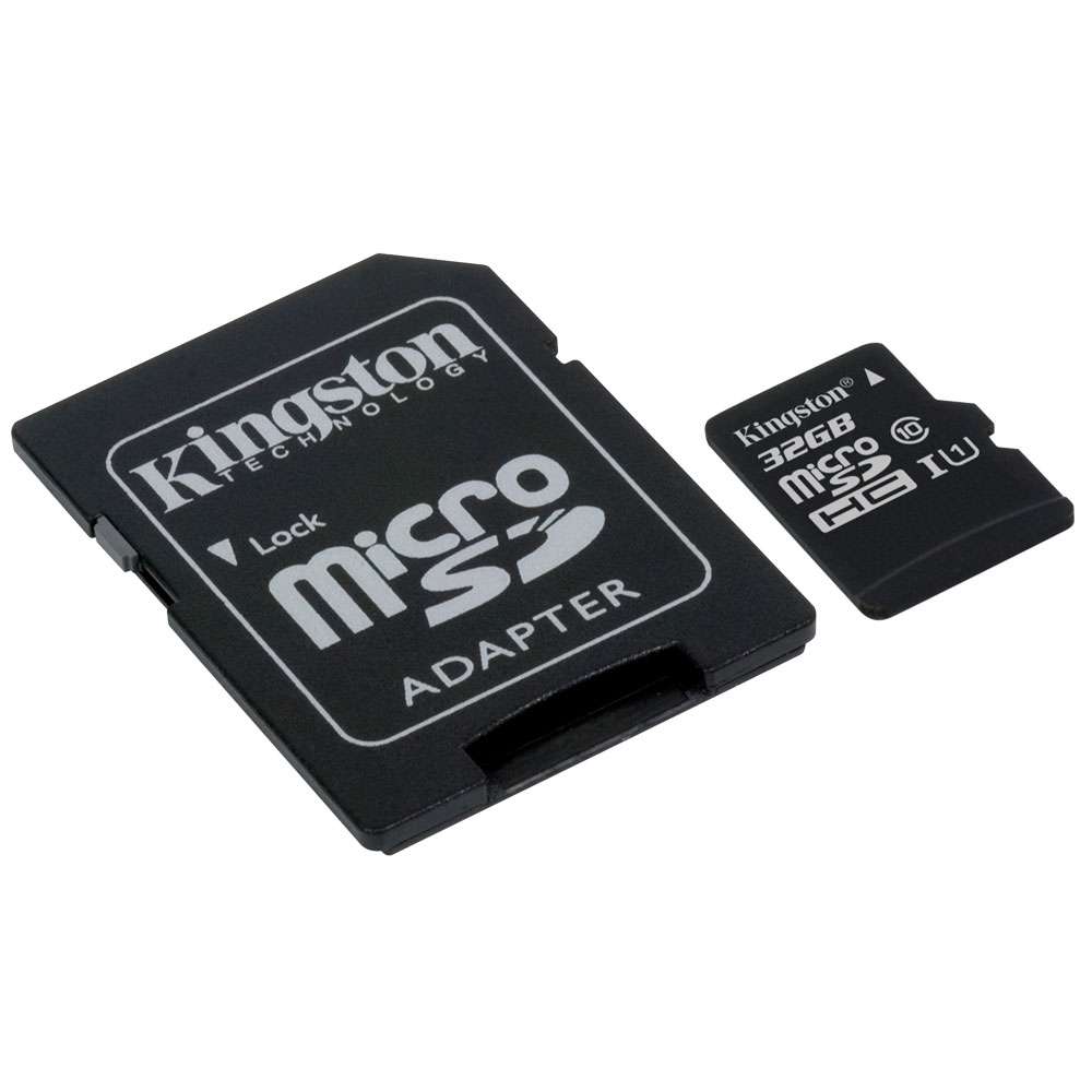
For this tutorial, the items needed to run this project are:
- Arduino Uno
- USB Cable type A to B
- Micro Sd Card Module
- Female to male jumper wire
- SD Card
Step 2 : Hardware Installation
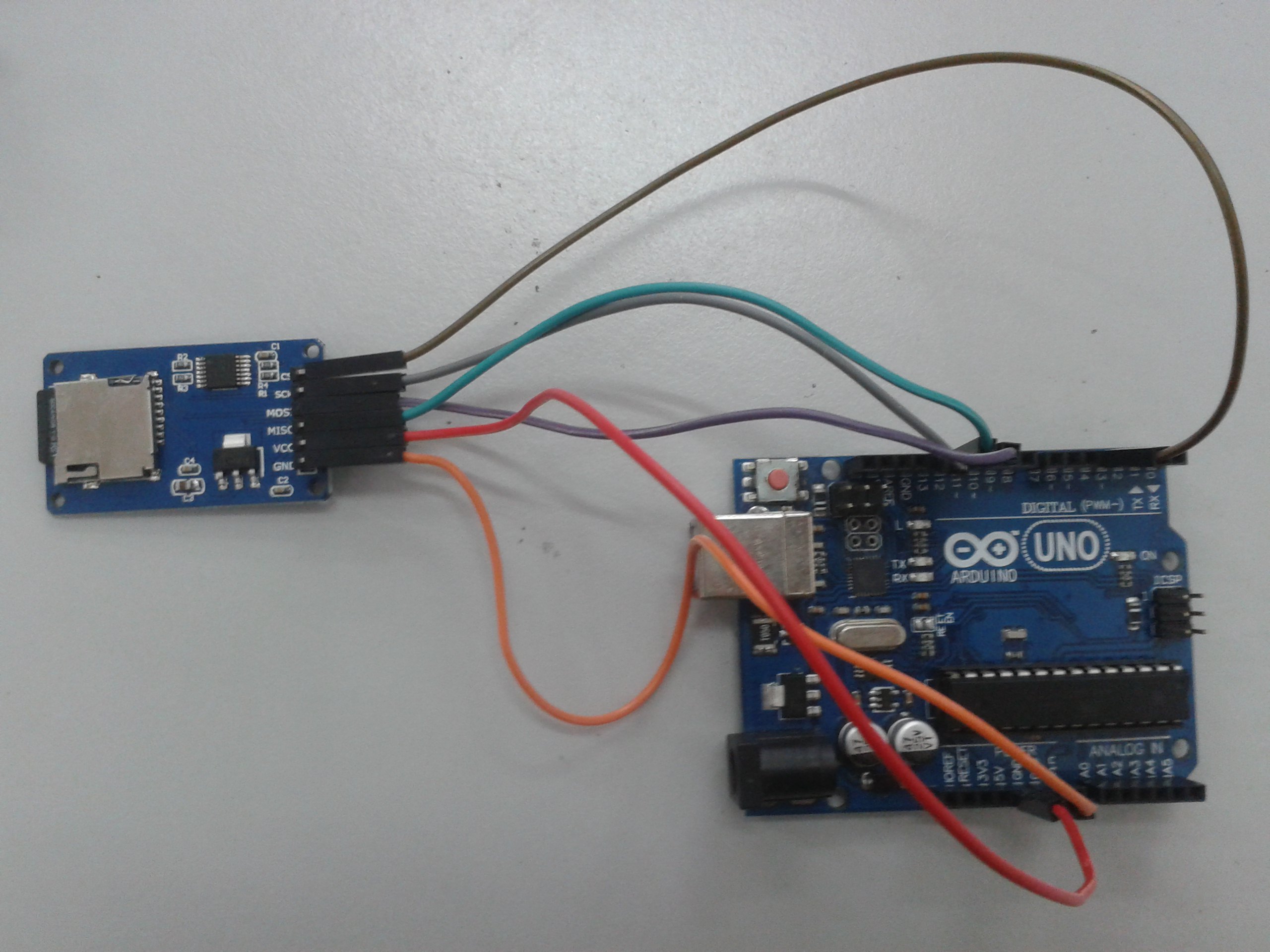
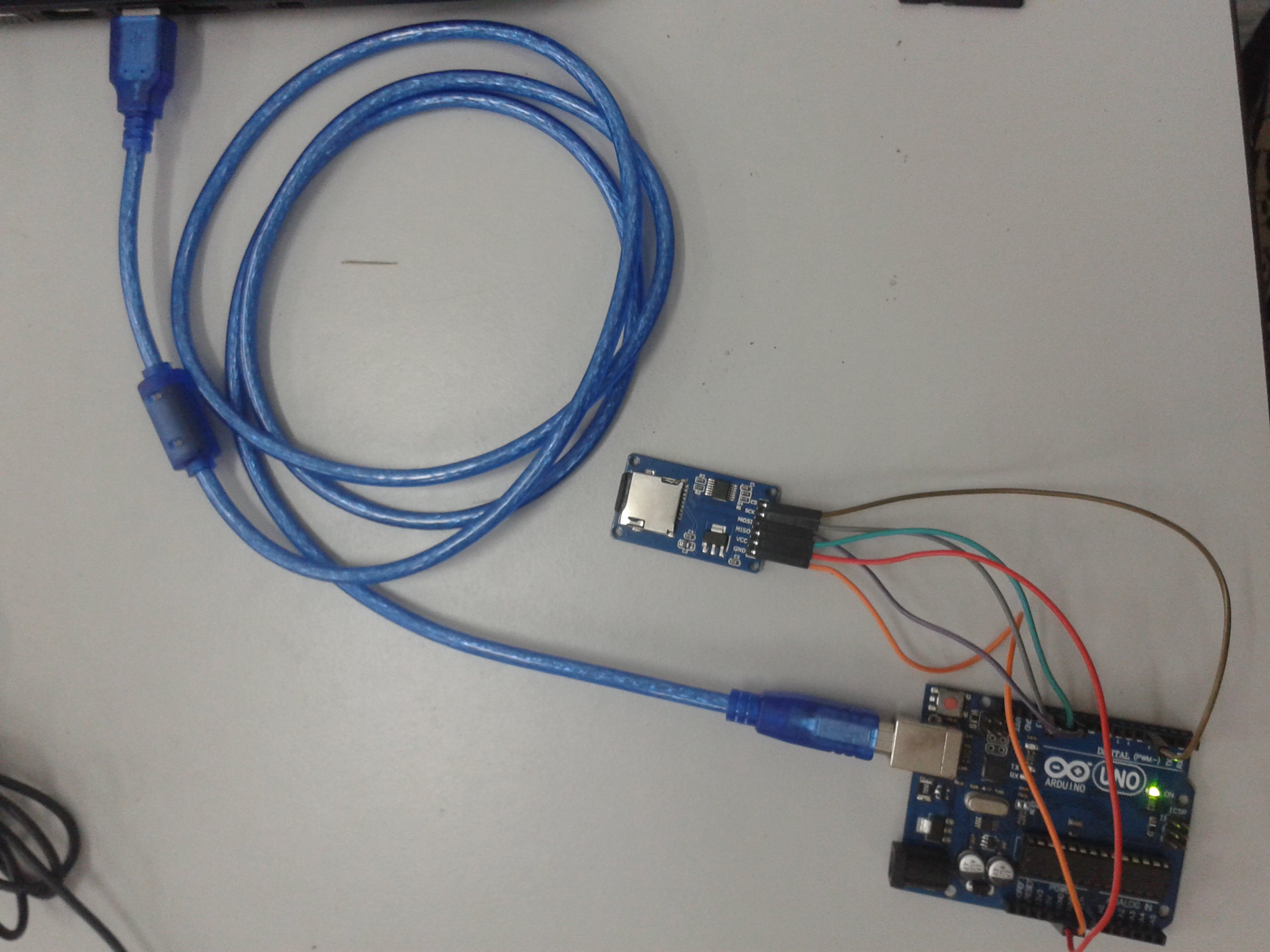
Micro SD Card Module
This module uses the standard SPI interface for communication, which involve SPI buses, MISO, MOSI, SCK, and a CS signal pin. through programming, the data can easily be read and wrote into SD Card by using the Arduino or other microcontrollers.
- CS (chip select)
- SCK (serial clock)
- MOSI (master out slave in)
- VCC (3.3V or 5V)
- GND (ground)
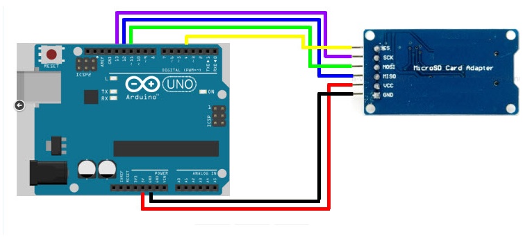
Diagram above shows the simple connection between Micro SD Card Module and Arduino UNO:
- Connect VCC with 5V in the Arduino.
- Then, connect the GND of SD card to the ground of Arduino.
- Connect CS to pin 14
- Connect SCK to pin 13
- MOSI connect to the pin 11
- Lastly, connect MISO to pin 12
After completing the connection, connect the Arduino to power supply with USB cable.
Step 3: Insert Coding
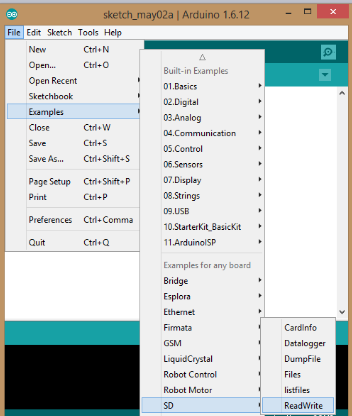
Lets try an example in the Arduino.
- Open the Arduino software
- Click 'file'
- Find the 'example'
- Click 'SD'
- Choose 'ReadWrite'
Step 4 : Choose COM Port
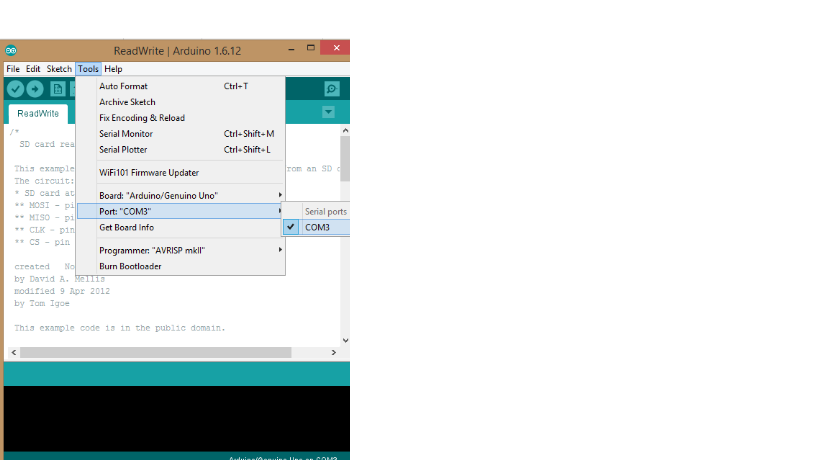
Just click at 'Tools', then choose your port available on your PC.
Step 5 : Upload Souce Code
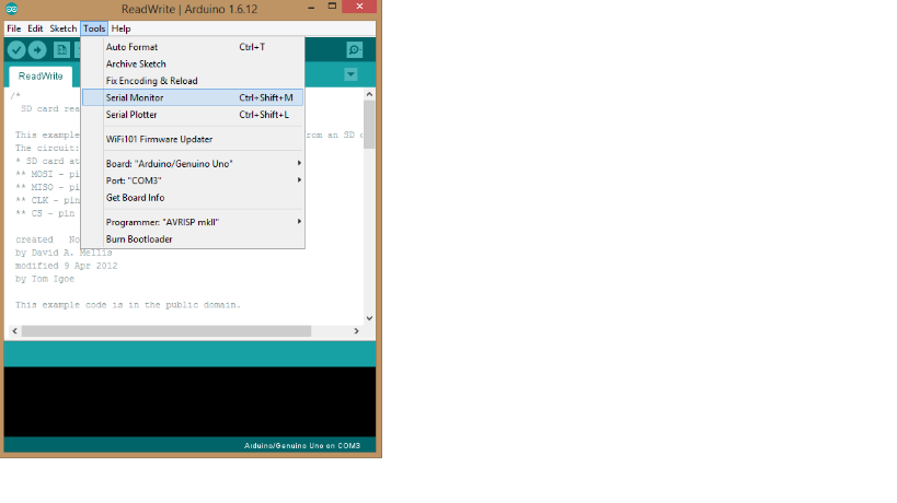
Upload the source code into the Arduino and open the Serial Monitor to se the result.
Ster 6 : Result
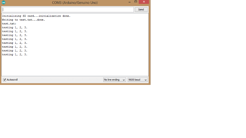
The following result will be displayed in the monitor. In this example, the .txt file named "test.txt" was created and the sentence "testing 1,2,3." were wrote into the .txt file. After this, the sentence "testing 1,2,3." were read back from .txt file and display on serial monitor.