"MegaPack" a 12V 5200mAh Battery Pack
by Arnov Sharma in Circuits > Electronics
9029 Views, 98 Favorites, 0 Comments
"MegaPack" a 12V 5200mAh Battery Pack


.gif)
.gif)
Hey, guys what's up!
So this is "MegaPack" a 12V Li-ion Battery Pack made in an exciting form factor.
I used PCBs with Li-ion cell Holders to make a simple PCB that holds Cells in a neat way, it has an OnBoard BMS which controls the charge and discharge cycle of the battery pack.
I've also added a Buck Converter to the one side of the PCB that outputs stable 5V for powering XYZ Arduino projects.
This article is about the whole built process of this Battery pack so let's get started!
Supplies
.gif)
These are things I used in this built-
- Custom PCBs
- Li-ion cells
- BMS 11.1V 3S
- Li-ion Cell holder SMD Version
- DC Jack
- MPS2314
- 10K Resistor
- 10R Resistor
- 7.5K Resistor
- 75K Resistor
- 40K Resistor
- 100uf Capacitor
- 10uf Capacitor
- 1H inductor
- Slide switch
- USB Port
- LED
- M7 Diode
- PCB Standoffs
Specs

Here are a few specs and features of this Battery Pack.
- 11.1V 5.2Ah Battery Pack with BMS for charging and discharging without damaging the battery from overcharge and over-discharge.
- I've added a Buck Converter circuit on this setup that bucks down 11.1V from the battery pack and convert it into stable 5V 2A Output through the USB Port.
- Charging time is usually 5-6 Hours if we use a 12V 1A Adaptor.
Schematic
.jpg)


So Above is the Schematic I prepared, it consists of a total of 6 Cells connected in a 3S 2P configuration, (S is series and P is parallel).
I connected Li-ion cells with the BMS in the right arrangement, Output of this battery pack is given by BMS, on the BMS there are certain MOSFETs and BMS Ics that monitor each cell voltage, if the voltage gets lower than the cell over-discharge rate which is 2.5 for each cell, it shuts down the output so we cant drain the cells up to 0V, if we drain the cell lower than 2.5V, Its capacity will be affected and it won't work properly later. BMS makes sure that each cell is charged properly which is 4.2V and stops the discharge at 2.5V.
I added a DC Barrel Jack with a Mosfet for charging the battery pack and also added the MPS2314 Circuit.
MPS2314 is a synchronous rectified step-down switch mode converter IC that offers 2A continuous output current over a wide input supply range with excellent load and line regulation, I've set its voltage under 5V which is enough to power USB Devices like an Arduino board for example.
PCB Design


After finalizing the schematic, I converted it into PCB File and prepared a Rectangular board in which I added an SMD Li-ion Cell holder on one side, BMS is placed near the Cell holder and an MPS2314 setup has been placed on one side.
I've added three more Cell holders at the bottom side of the board.
I added holes at all four sides, my plan is to add PCB Standoffs with these holes and attach another PCB at the end side to make a sandwich layout.
By this method, we dont have to prepare a casing or enclosure for this Battery Pack, its PCB is itself the body.
After completing the routing, I exported the Gerber data and sent it to PCBWAY for samples.
PCBWAY
.gif)
.gif)
I received the PCBs in a week which was fast.
I choose Blue Soldermask for this project with a white silkscreen and the overall quality of the PCBs was just awesome.
I have Been using their service for a while and I have to say, it's pretty decent for getting started.
Checkout PCBWAY from here- https://www.pcbway.com/
PCB ASSY
PCB Assembly of this project contains the following steps that also include testing the board before adding components on the bottom side.
- Solder paste Dispensing
- Pick & Place Process
- Hotplate reflow process
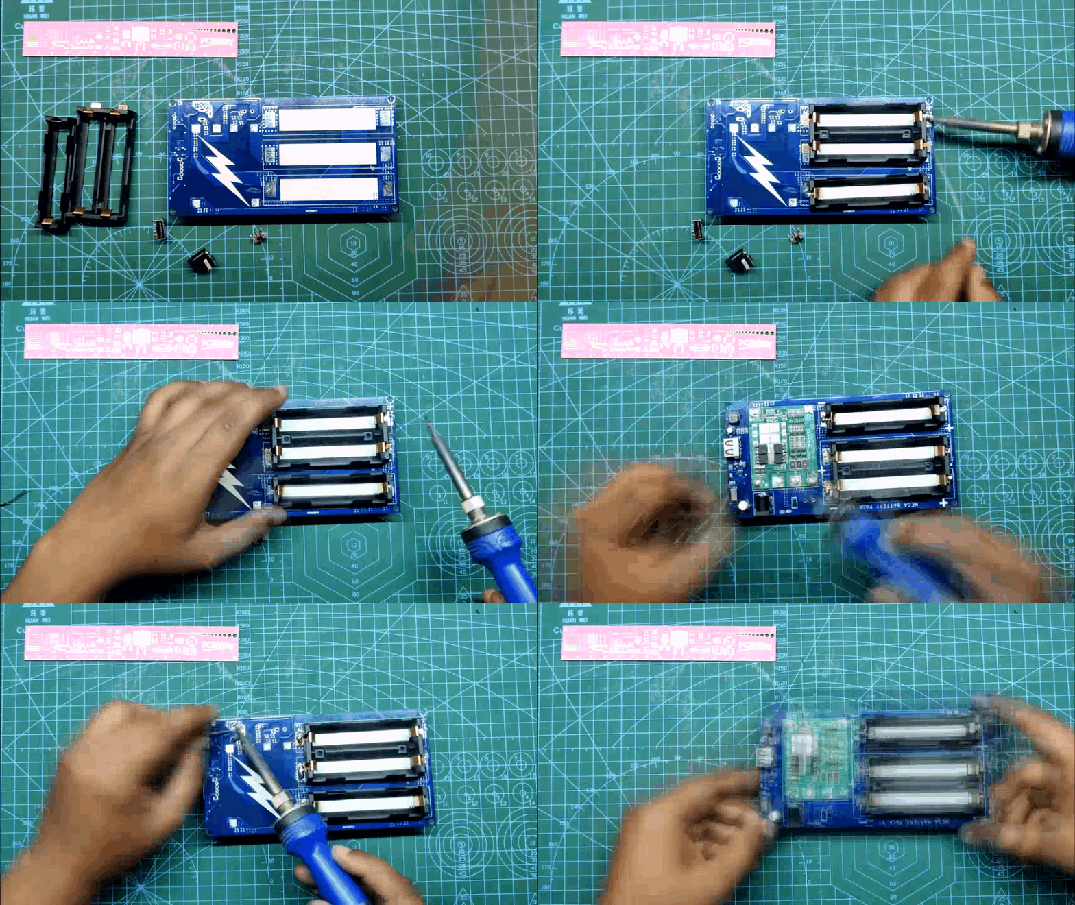
- Adding THT components and Cells holder on the Bottom side
- Testing Process
SOLDER PASTE DISPENSING
.gif)
.gif)
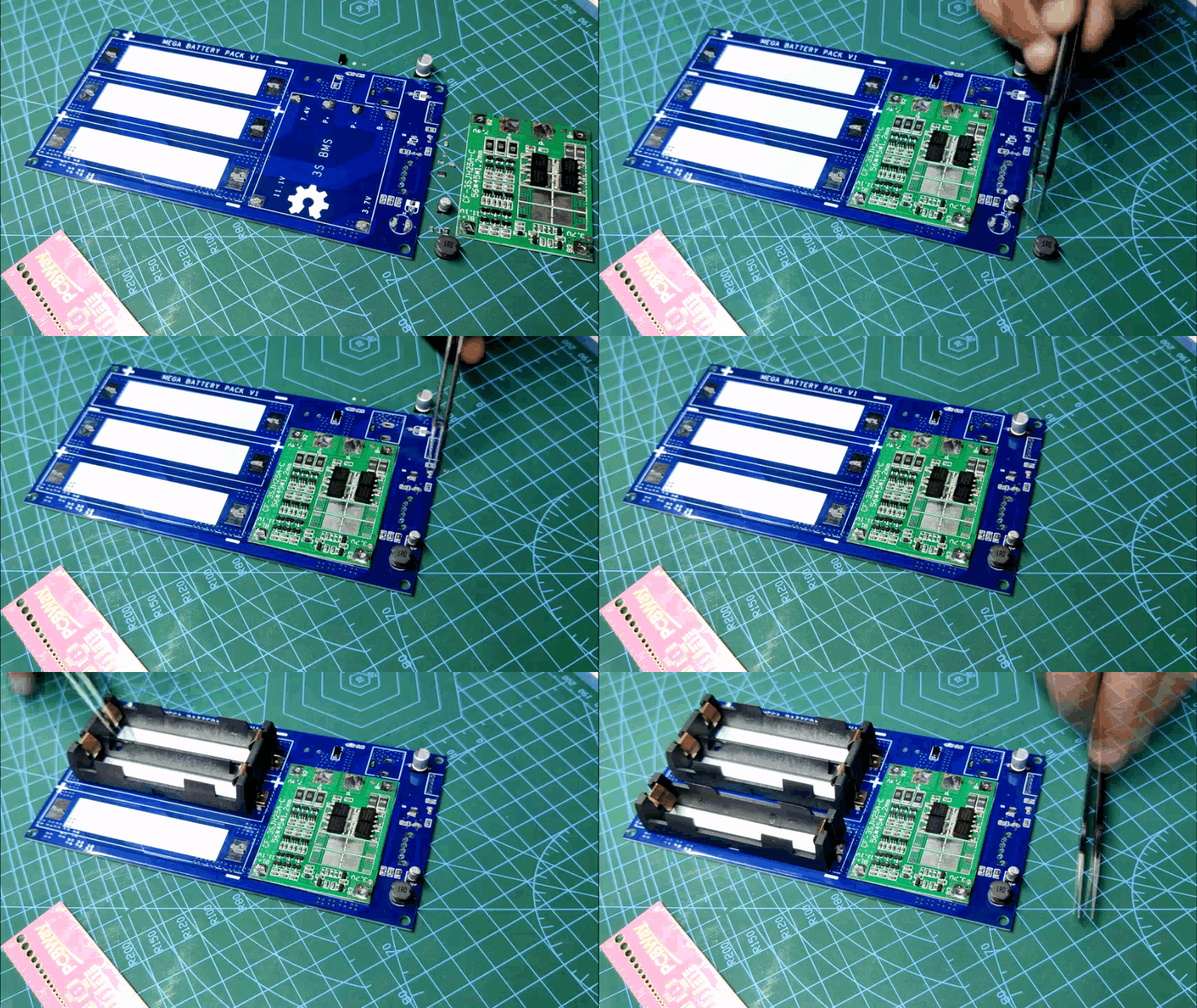
I first added solder paste to each component Pad with a solder paste dispenser.
Pick & Place Process
.gif)
Then I used my ESD Tweezer to Pick each component and place it in their assigned place one by one. This process is for the TOP Layer only.
Hotplate Reflow Process
.gif)
.gif)
.gif)
Next, I lift the PCB and put it on an SMD Hotplate.
SMD Hotplate heats this PCB from Below up to the solder paste melting temperature. As soon as the solder paste melts we remove the PCB from the Hotplate without shaking it as the solder paste is still liquid at this point.
Adding THT Components
.gif)
After inspecting the Solderpaste process for TOP Layer, I added the remaining THT Components along with the SMD Cell holder on the Bottom side with a Regular soldering Iron.
Result So Far
.gif)
.gif)
.gif)
After inspecting the overall solder joints and components, I carefully added Li-ion cells to their Cell Holder.
I added them with super caution with the right polarity as if I connected the cells in the wrong polarity, the whole board might catch fire. (BMS will catch fire)
Polarity marking is already added on the PCB so I use it as a reference while adding cells and after this, nothing caught fire.
Charging Port
.gif)
I first added the charger to the DC jack and check if the charger was working.
USB Side
.gif)
I then added a USB Power meter to check if the Buck converter side is working which was working properly.
Adding PCB Standoffs
.gif)
To give this board structural strength and a rigid body, I added four PCB Standoffs and connected them with another PCB that doesn't have any componenets.
Testing Battery Pack Output
.gif)
.gif)
.gif)
After adding standoffs, I used my multimer to check the output voltage of the battery pack which was 11.2V, after checking the voltage, I added a CON2 Connector at the output side so we can add any battery-operated device like a motor for example.
Powering a Motor
.gif)
.gif)
I used a 12V Gear DC motor for testing this setup, I added its positive and negative wire with the connector, and the battery pack powered the motor without any trouble.
Powering Arduino Project
.gif)
At last, I added one of my previous projects which was this neopixel light through the USB Side of the battery pack and it was working as well so this concluded that both 12V and 5V sides are working and this project was a success.
Conclusion

.gif)
.gif)
.gif)
Both the 12V side and 5V side were working, I made this battery pack for a Robot project that will be powered by an MCU that uses 5V but the motor driver uses 12V so I made a battery pack with a buck converter inbuilt that will power both MCU and motor driver.
After testing the board, I added another standoff and PCB Layer on the TOP side that makes this PCB a three-layered project, main circuit is in middle and is supported by both sides through standoffs and PCB. kinda like a sandwich, with a pattie in the middle and two bread pieces on both sides.
This is all for today folks, comment or DM me if you need any help regarding this project.
Thanks, PCBWAY for supporting this project, do check them out for getting great PCB or PCBA services for high quality and low prices.
Thanks to you all for reading this article and I will be back with a new project soon!
Peace