MegaMUX - 32 Channel Multiplexer Tutorial
by seanhodgins in Circuits > Microcontrollers
21336 Views, 64 Favorites, 0 Comments
MegaMUX - 32 Channel Multiplexer Tutorial
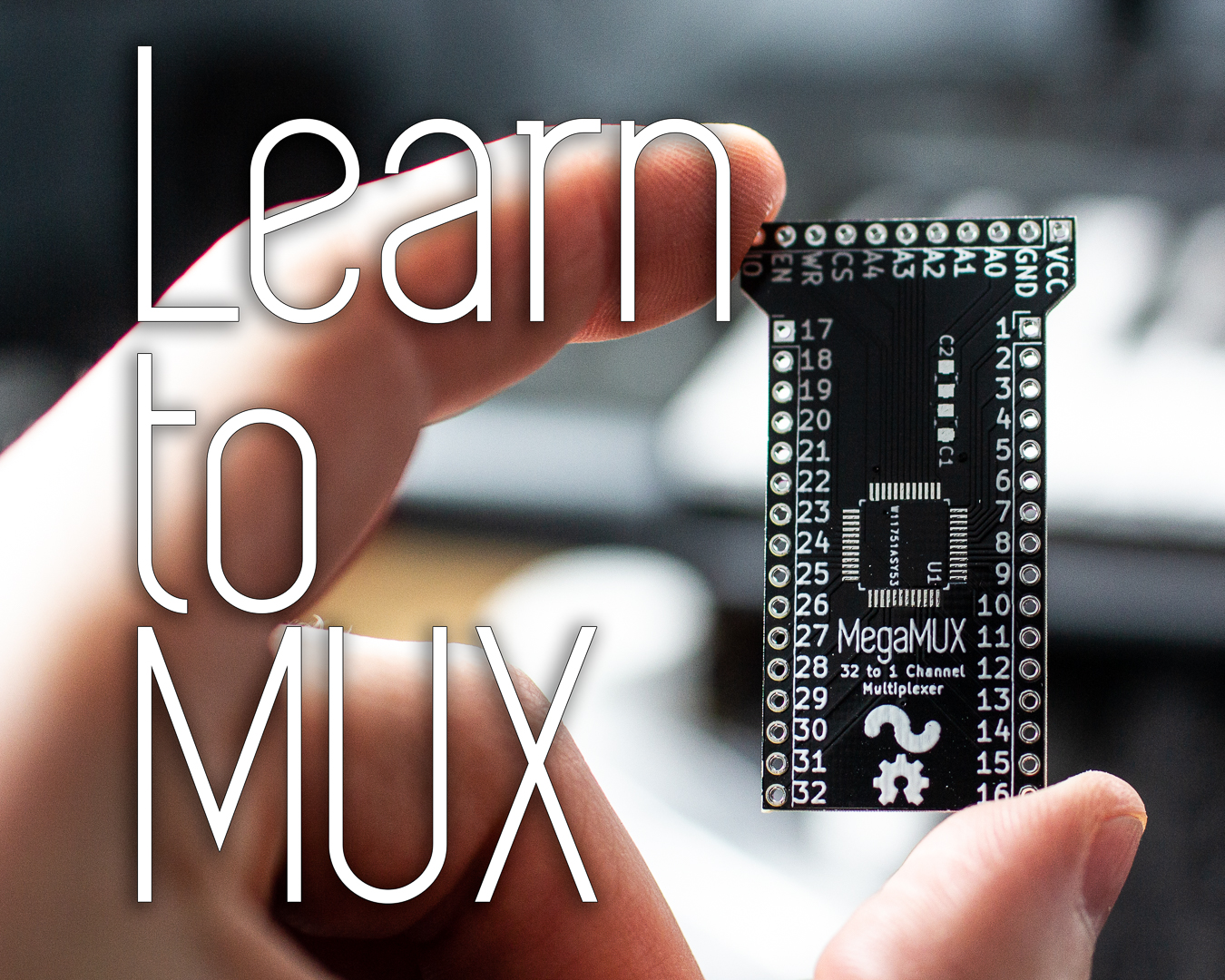
Often when I have an idea for a new project, it will involve some components or circuitry that I have not used before. To be safe, I will sometimes design a smaller "test" board with just that component or circuit to test it out before I design the larger project. This is where the MegaMUX comes from. I wanted to test out the ADG732 multiplexer which is a 32 channel MUX. This means you can connect one output from the MUX, and select 32 other IO to connect to it. In this project I will show you how to connect the MegaMUX to an Arduino, and give you an idea of what you can do with it.
Watch the Video!
The video has a lot of info, and I go through how the Arduino programs work in detail. Enjoy!
Get the Parts, Components, and Tools.
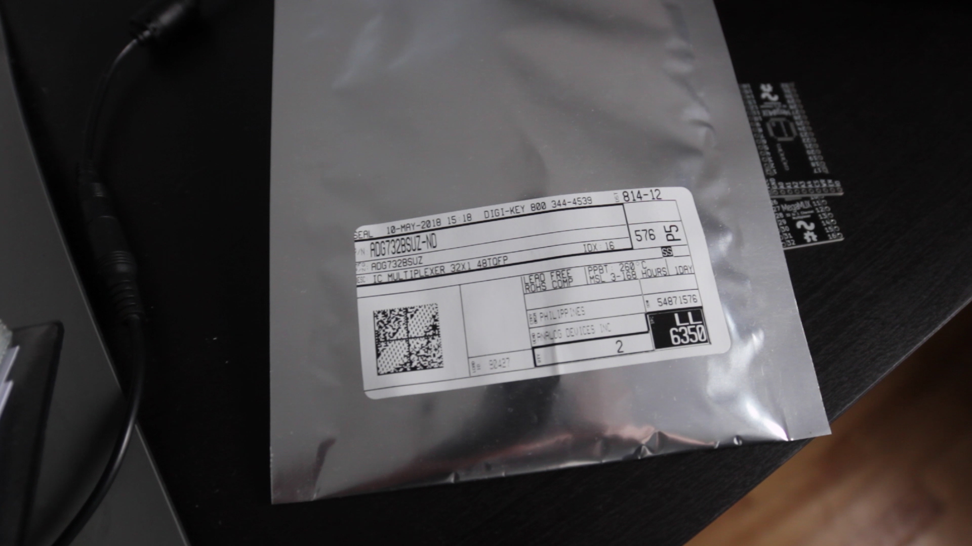
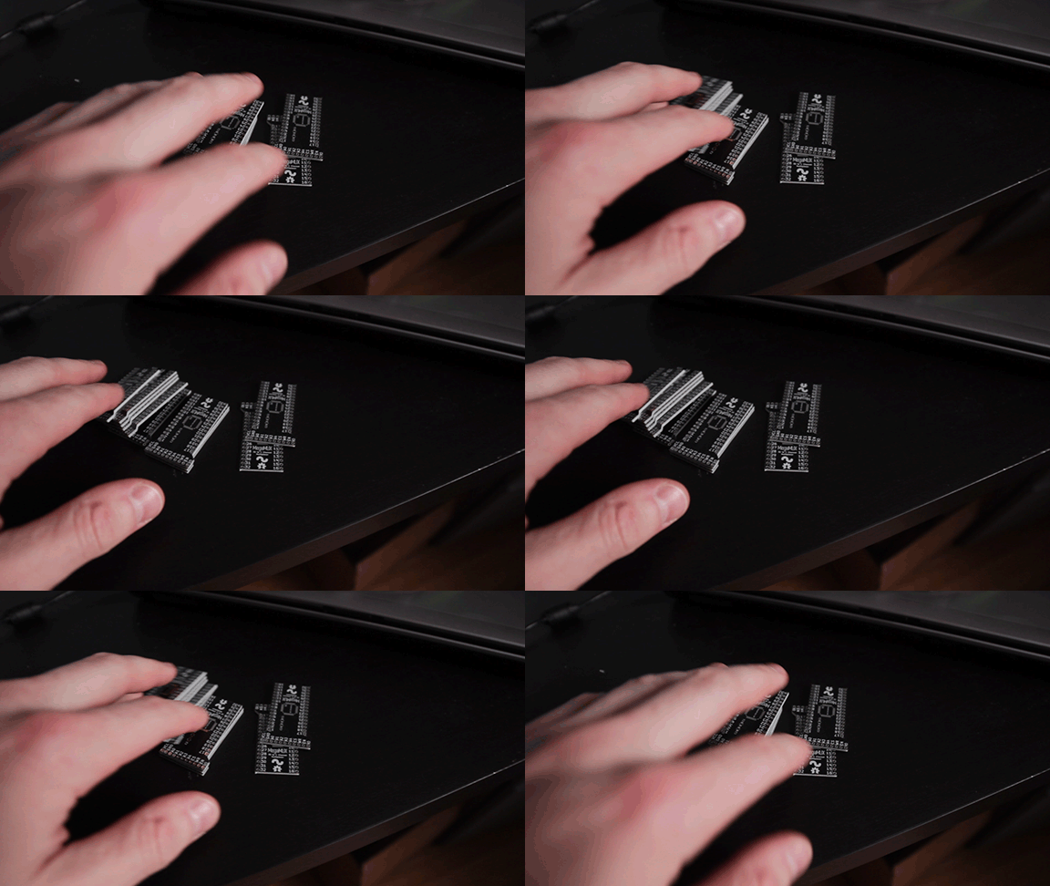
This is a very basic board so there are only three components on it. For the MegaMUX you need:
Parts:
- Arduino Board, I use the Sparkfun SAMD21
- Jumper Wires
- Breadboard
Tools:
- Soldering Iron
- Solder
- Solder Flux
- Tweezers
Solder on ADG732, Caps, and Header Pins
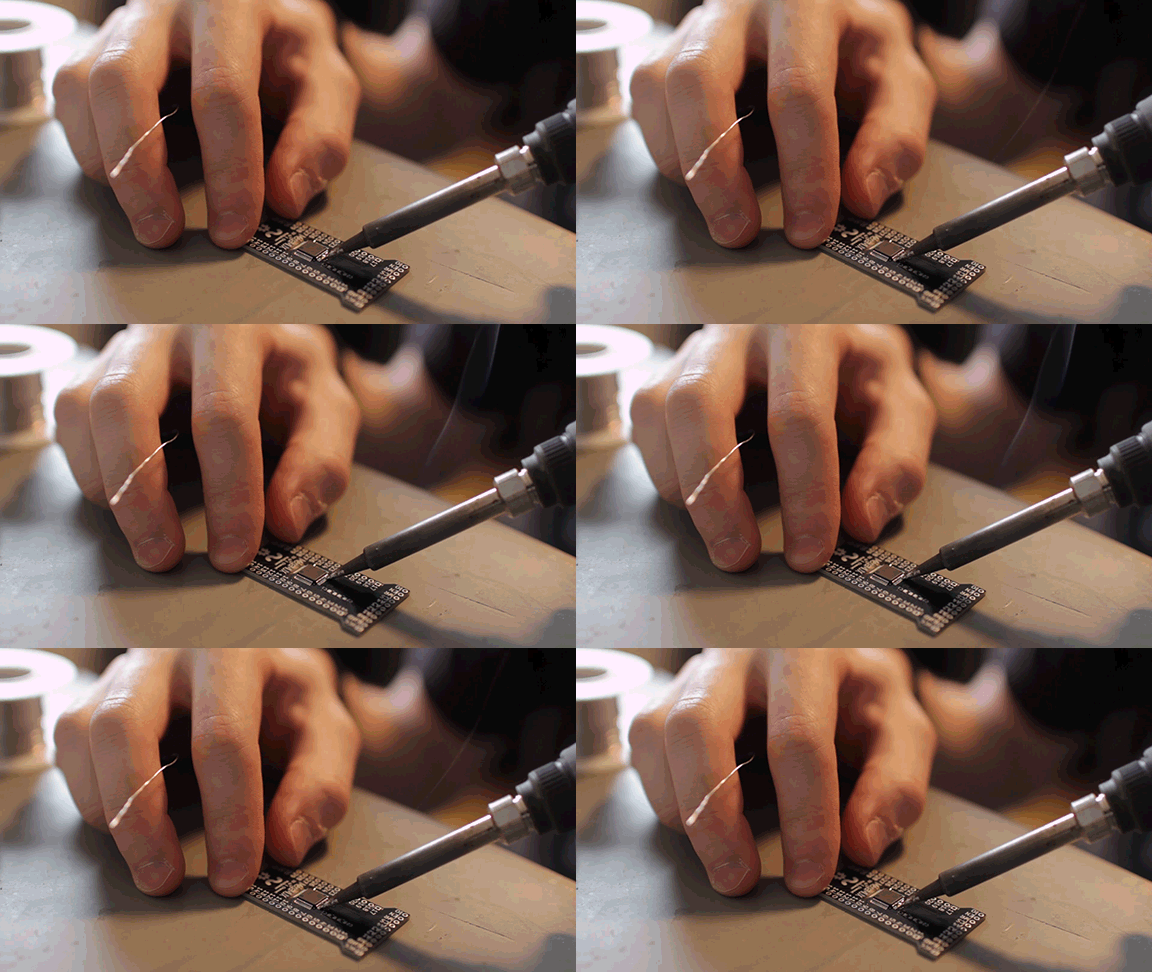
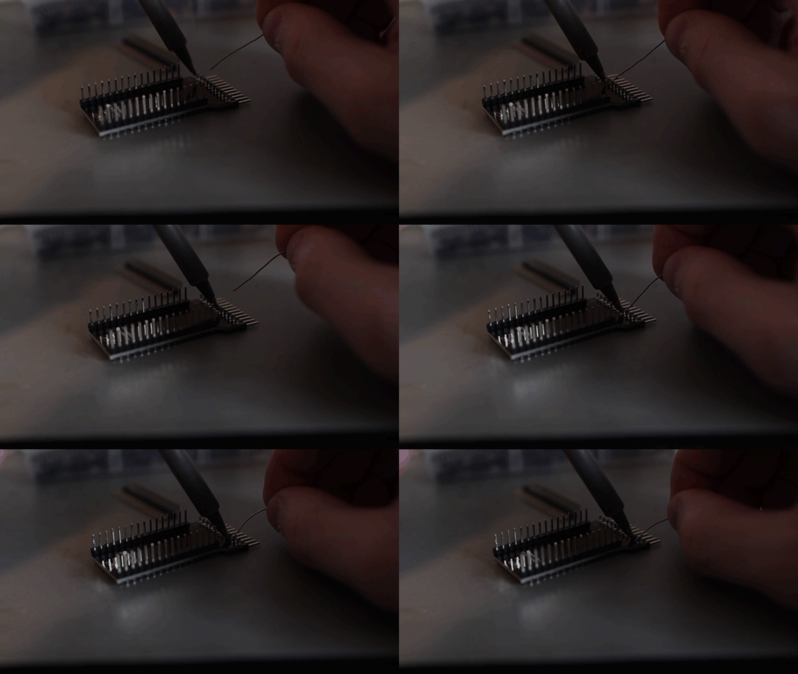
Since I'm only making one or two of these, I'm just using my soldering iron to place the chip. Use whatever method you're comfortable with.
I soldered on the header pins so they could be placed in the breadboard with the IO right angle pins sticking out the back.
Connect It to an Arduino
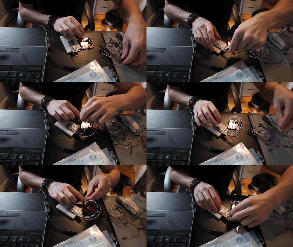
If you would like to use my demo programs, connect the IO as shown below. Left is the MegaMUX, right is the Arduino.
- VCC -> 3.3V
- GND -> GND
- A0 -> GPIO13
- A1 -> GPIO12
- A2 -> GPIO11
- A3 -> GPIO10
- A4 -> GPIO9
- CS -> GPIO8
- WR -> GPIO7
- EN -> GPIO6
- IO -> A0
Testing Output Program
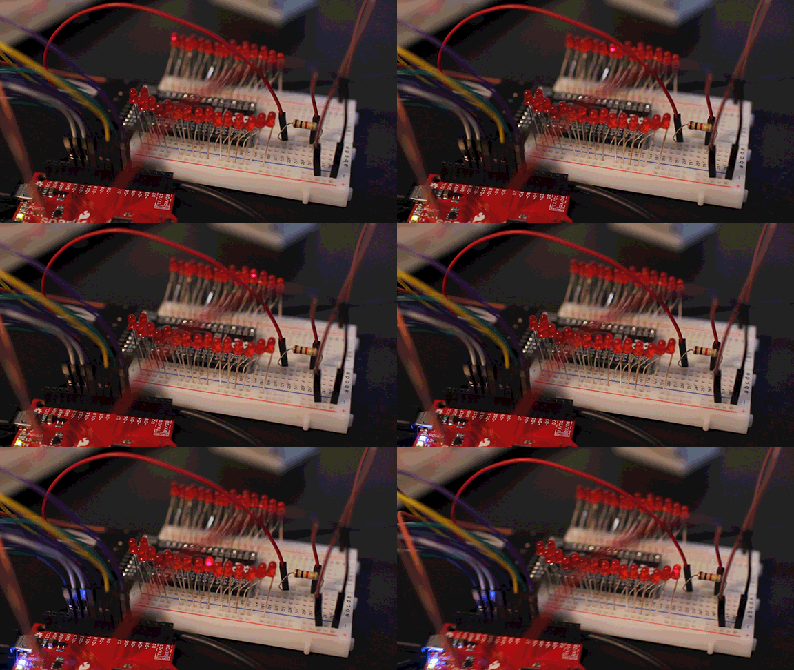
If you would like to use the program to test outputs on the MegaMUX, connect each IO pin of the MUX to an LED. Connect a suitable resistor between IO on the MUX and A0 on the Arduino.
Download my Arduino Program and upload it.
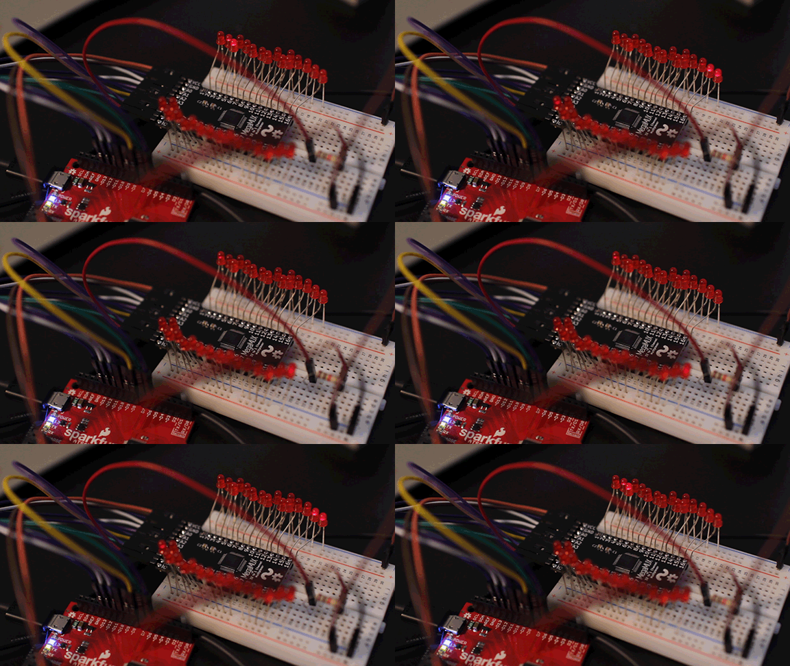
If everything is correct the LEDs should be lighting up one at a time cycling through all of the pins.
Downloads
Testing Analog Input Program
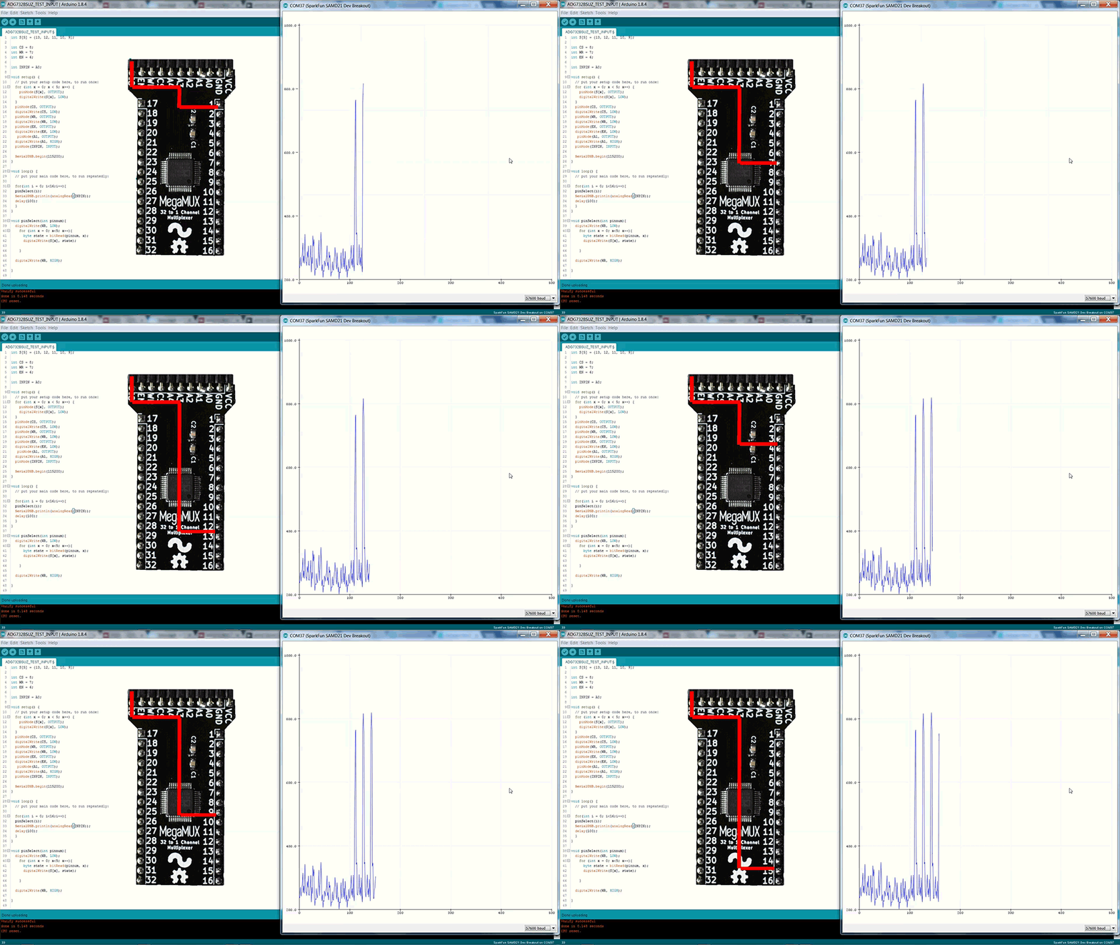
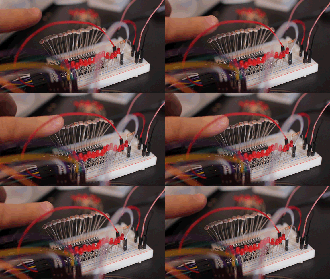
If you want to use your MUX as an analog input, I used photoresistors as a demonstration. The photoresistors are added on one side of the mux(IO 1 to 16) instead of the LEDs. I setup the output pin to be a voltage divider. Each time the pin is switched the next photoresistor will become the other half of the voltage divider and report to the analog pin of the Arduino.
Download the INPUT program and upload.
The program will cycle through the photoresistors, allowing you to sample from each one. You can see this if you open the "Serial Plotter" in the Arduino IDE.
If you haven't yet, watch the YouTube video on details how the program works.
Downloads
Learn Something New
Now that you have setup your MegaMUX and played around with the Arduino programs, try and come up with your own use for the board. This basic idea is that this expands the GPIO on the Arduino. Leave a comment on what you used it for!
Support These Projects!


If you haven't noticed yet, my goal is to bring fun, interesting, educational projects that are available to everyone equally with zero pay walls. However, these projects do cost me both time and money in developing them. If you enjoy these free open source projects, and can spare a few dollars a month, please consider joining my Patreon. Patrons help support future projects, so I can continue to bring more content to everyone!
If you want to keep up to date on my projects, subscribe to my YouTube! Watching and sharing my videos is another way to support what I do.
And finally, follow me on Twitter and Instagram, where you will find behind the scenes content for future projects. Its also an easy way to ask me questions.