Mega-Rumble Gaming Vest! AKA: the Tooth-rattler! UPDATE With Gameplay Video
by Orionpax60 in Circuits > Wearables
1055 Views, 4 Favorites, 0 Comments
Mega-Rumble Gaming Vest! AKA: the Tooth-rattler! UPDATE With Gameplay Video

If you have a teenager, and a console - then you have a bin of broken gaming controllers. Rather than leaving them to languish in the bowels of a closet, or to be lost in the corners of a closet re-purpose those glorious contraptions into something grand: a Mega-Rumble Gaming Vest! AKA: The Tooth-Rattler!
The idea of a haptic vest, that’s not only easy to assemble but within the budget of most consumers also intrigued me. As a High School English teacher and S.T.E.A.M. (Science Technology Engineering Arts Mathematics) educator, this is a great beginner project that all students will find rewarding, and you’ll have the added bonus of re-using and re-purposing tech., which would otherwise rot for 10, 000 years in a landfill on the outskirts of town.
Supplies

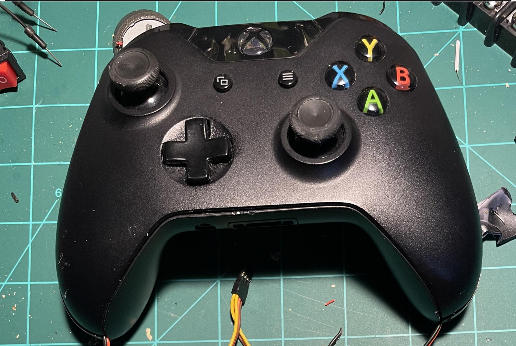


- One (fully operational) XBOX ONE, XBOX 360, or PS3 controller with rumble capabilities AND can output at least 3 volts
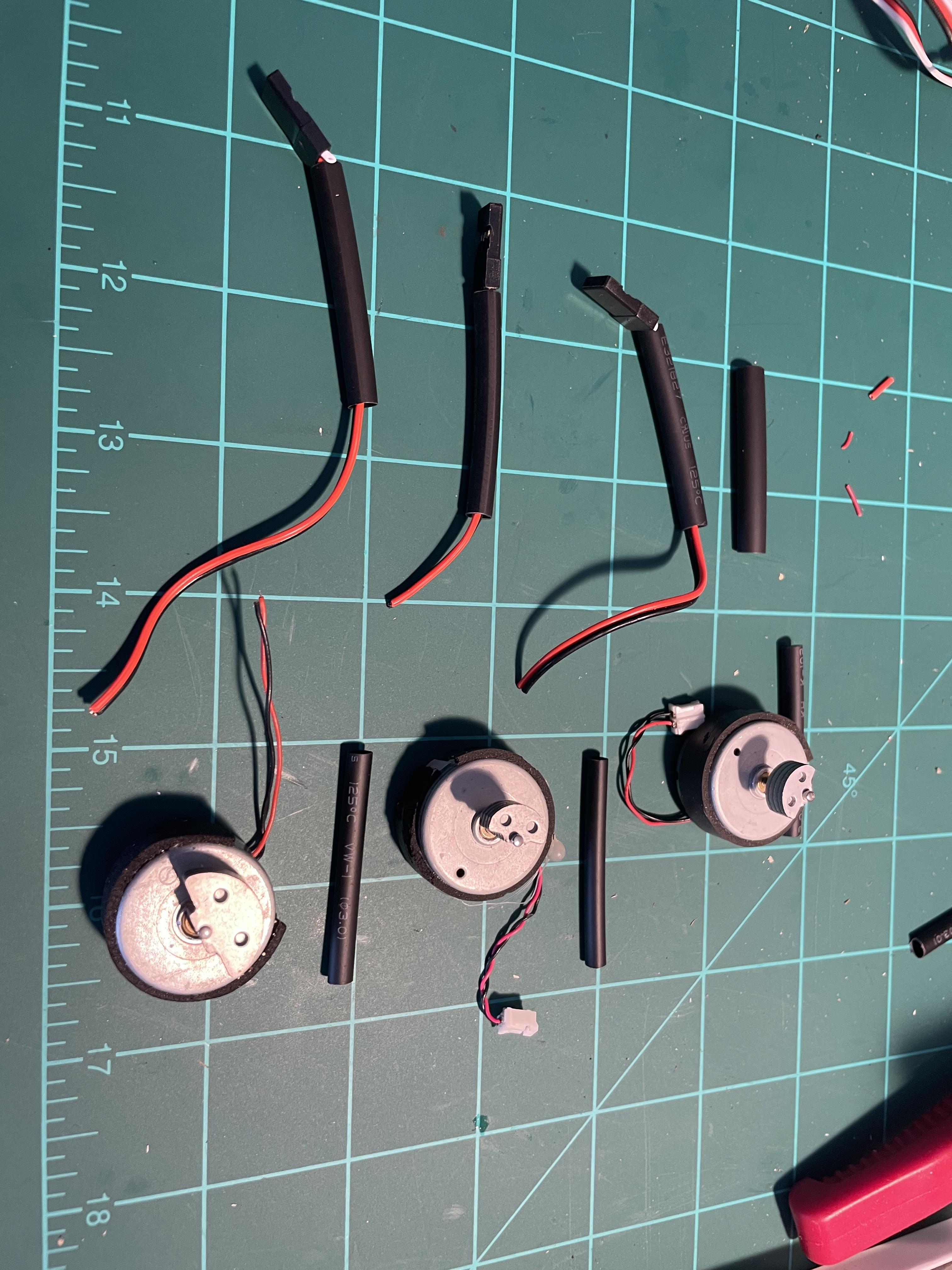
- Four (or more) rumble motors
- Four-to-six 8-inch servo wires, two “y” servo wire extenders/connectors, and a Long micro-USB wire to hard-line power the gaming controller
- 2-4 relay switches, and a 3D printer (I own a Creality Ender 3, and a CR10S)
- Either a few discarded canvas/mesh belts or a $20 Home Depot Workman’s pair of suspenders (this will be your harness to hold the vibrating motors)
- Soldering Iron, Solder, wire cutters, needle-nose pliers, 16-32 AA batteries and holders, and a small flathead screwdriver
Tear-down and Harvest Your Materials


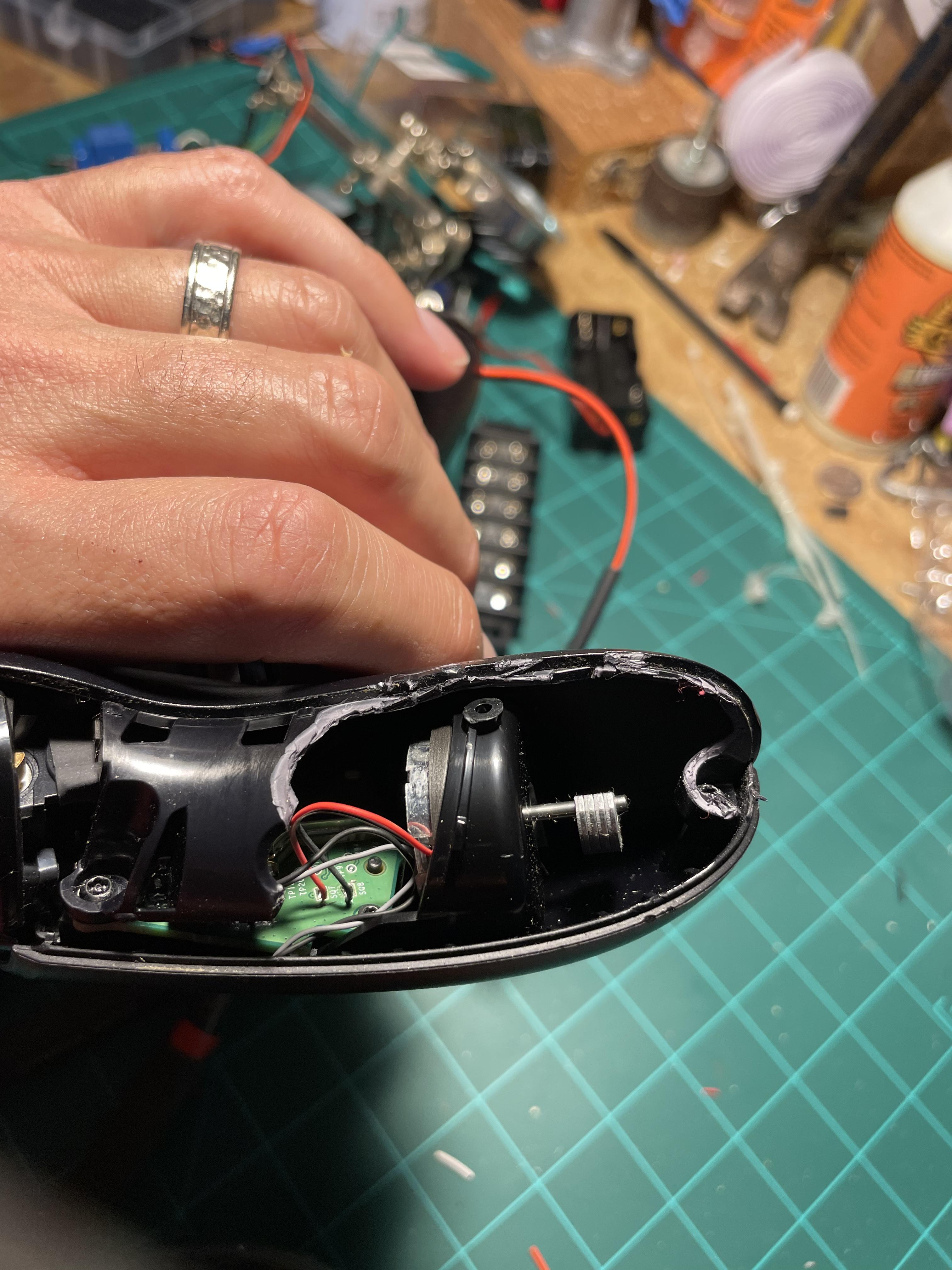

CAUTION: any missteps in this process and you could very well destroy your only working controller - rendering your game console useless until you purchase another.
Salvaging your rumble motors must be the first step in this process, in the best-case scenario you will have six total motors to work with (two within your controller, and four others that will be mounted on your vest). The controllers pictured above are from an XBOX ONE and weren’t too difficult to disassemble; these controllers require a special tool to remove the necessary screws. Instead of purchasing said tool, I grabbed my caveman wire cutters and tore a small hole in the underlying plastic to access the rumble motor wiring beneath.
Always save your remaining controllers - each controller is a wealth of electronics to harvest! Caution: the wires that are attached to the rumble motors are rather thin and frail, strip these wires with care.
In this next phase, you will have to remove the outer shell of your model 1697 XBOX ONE controller. There is a special, heavy plastic tool, that you should use (so as not to damage or scratch your controller), but I do not have such a tool. I chose to use a small, flathead screwdriver.
Along the controller’s edge is a fine seam that you can wedge your screwdriver into. Do not force the tool into the controller, but stay along the very edge of the seam where the bottom where your fingers would rest if you were holding the device. This shell will easily pop off once you release the attaching clips.
Now we’re inside your $60 controller. WARNING ONE: before you progress realize that you are butchering a rather expensive, and needed, accessory for your gaming console. You could be ruining your controller.
A protective casing surrounds each rumble motor, if you have the proper screwdriver you can remove the inner protective shell without injuring your controller beyond repair. As you can see from the images that I posted above, it’s obvious that I used a rather sharp set of wire cutters to remove sections of plastic just above the rumble motors on each side of the controller.
WARNING TWO: If you take the barbarian route in this step then you also risk severing any and all of the wires beneath the plastic shell.
Please note: you want to have the FEMALE servo wire end come out of the controller so that you can attach the “y” servo wire thereafter.
We want the red and black wires that run from the circuit board to the rumble motors, there isn’t much room to work here, so again, be careful. Cut the wires, and then splice them back together, leaving the cut wire exposed to be spliced to one end of the 8-inch servo wire. This part is simple: black to black, and red to red. You can remove the third white wire on the servo wires now. Solder your spliced wires, and then slide your heat shrink over the new connection. Rinse-and-Repeat for the other side of the controller. As a young Tinkerer, I always chose black electrical tape for any and all projects, but trust me and spend the money: get yourself a large box of heat shrink - you can’t beat the insulation and security that these little tubes offer.
Your controller is now ready to accept the additional rumble motors!
Boot up your CURA program, level your printer bed, and get ready to wait for your necessary rumble motor mounts. I printed these on “low quality” (.28 mm) and it took my Creality Ender 3 four hours and thirty-eight minutes to print five mounts. This motor mount was created exclusively in TinkerCad and is attached below as both the necessary .gcode, and as an .stl file for further tinkering.
Snip, Solder, Heat Shrink, Rinse and Repeat


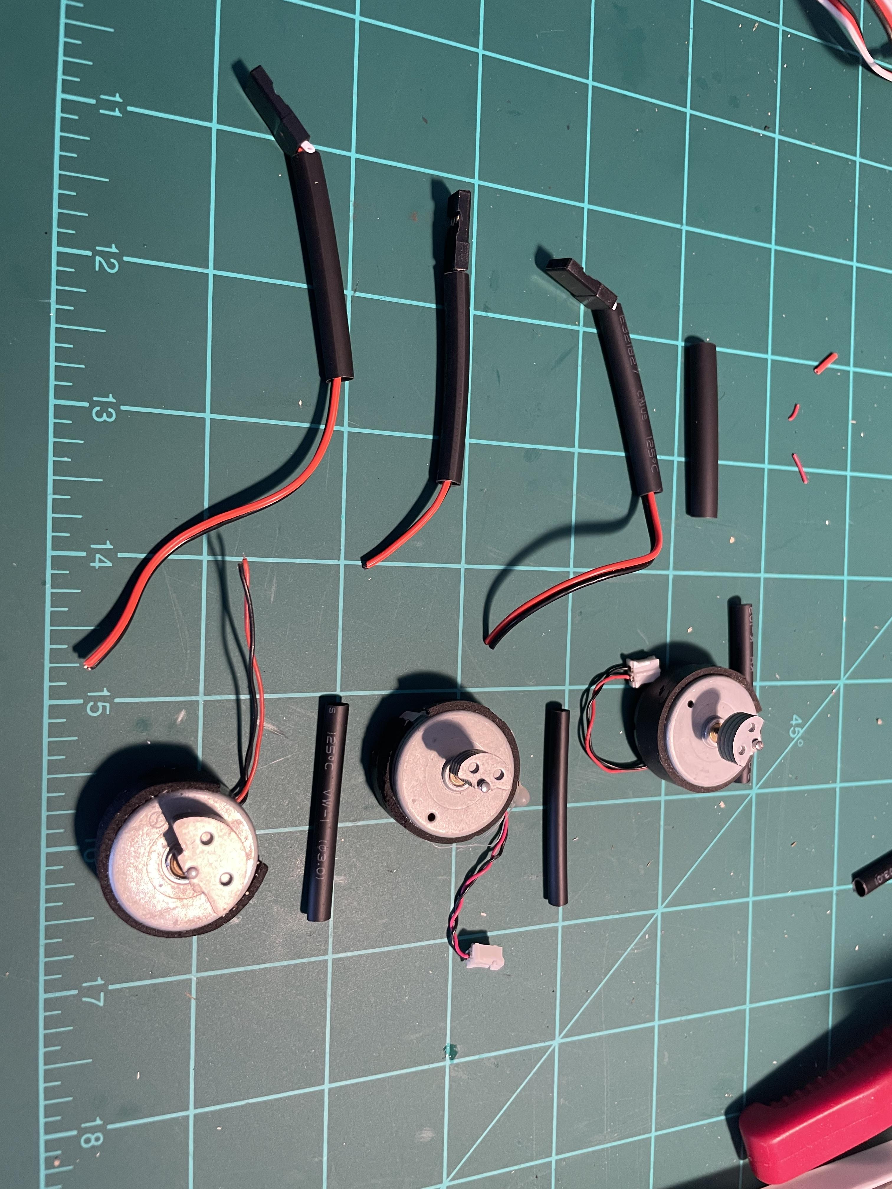
Stripping and soldering wires don’t require a lengthy set of instructions, but I will suggest that you:
- Cut the FEMALE end of the servo wire away, leaving about an inch of wires attached for later use. If you’re on a budget you can make your own “Y” connectors using two discarded FEMALE connectors, and one MALE connector.
- Strip wires with care, especially when dealing with your rumble motors. They have very limited wire to work with.
- After stripping your wires, remember to slide your heat shrink tubes over the wires BEFORE you solder your wires. Forgetting this step could mean re-stripping your wires and begin again. Not insulating wires will absolutely cause a short and ruin your controller. I speak from experience because I made this same mistake on the third rumble motor.
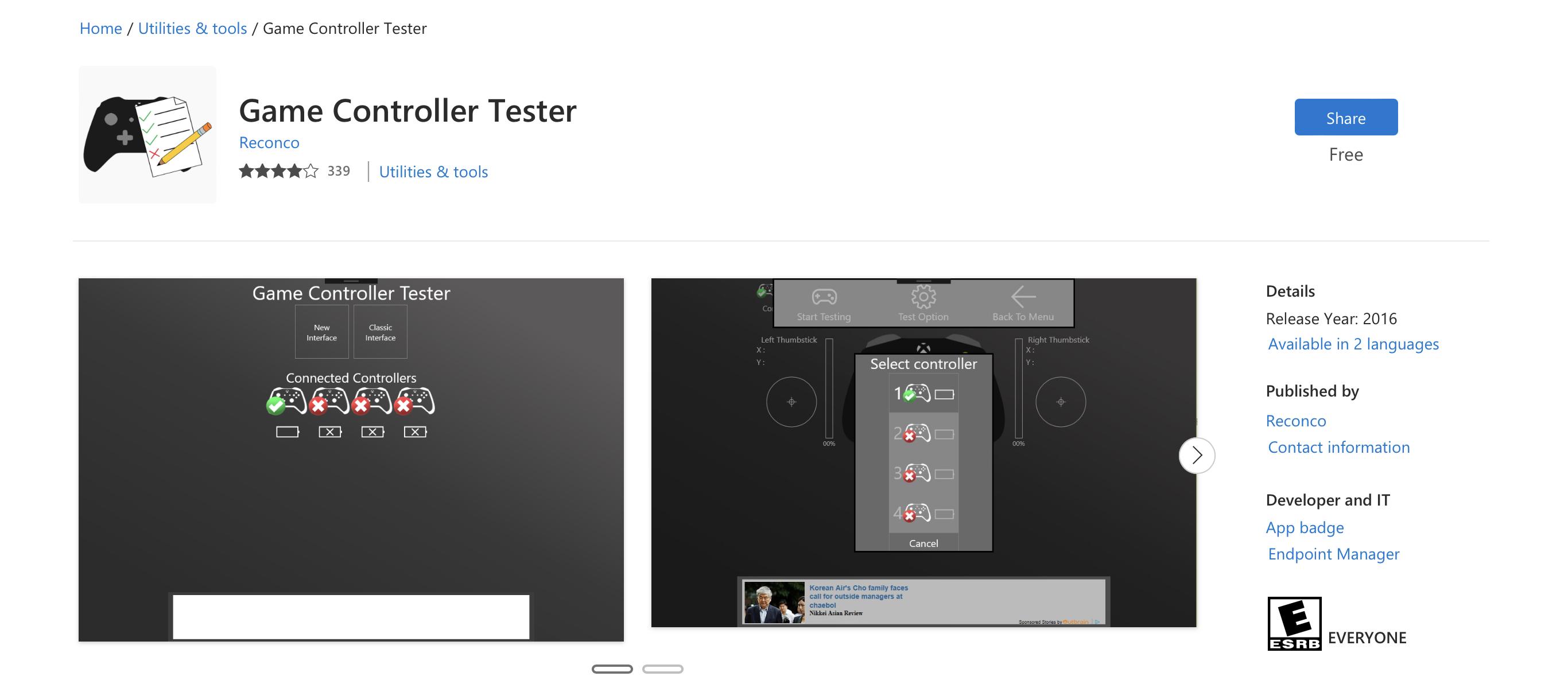
Test your newly modified controller by connecting it to a PC and running the “Game Controller Tester” app that’s FREE from the Microsoft APP Store. The attached shows the controller using this program to test the rumble motors.
Relay Switches: With Just 3.3v You Can Control the World!
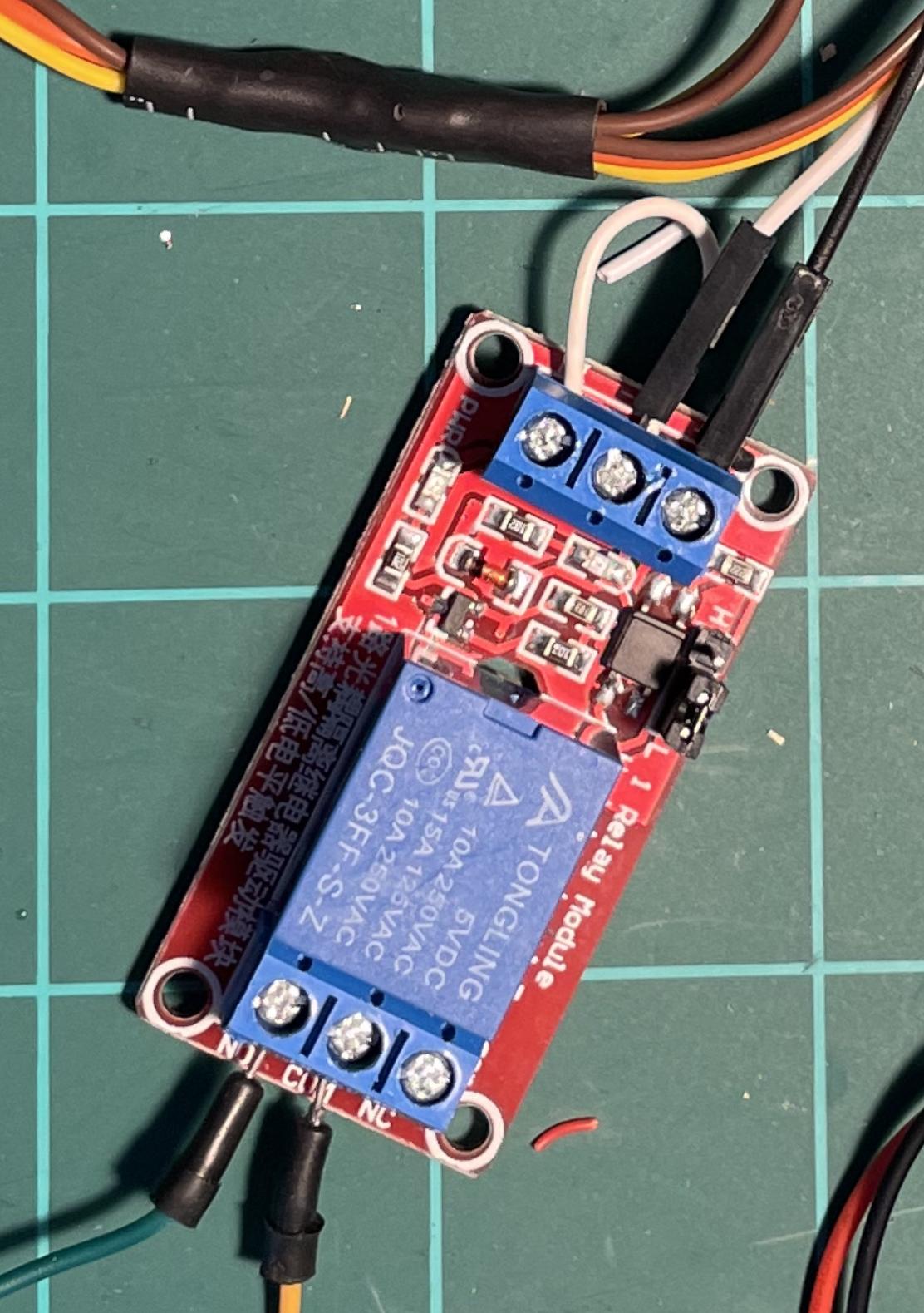


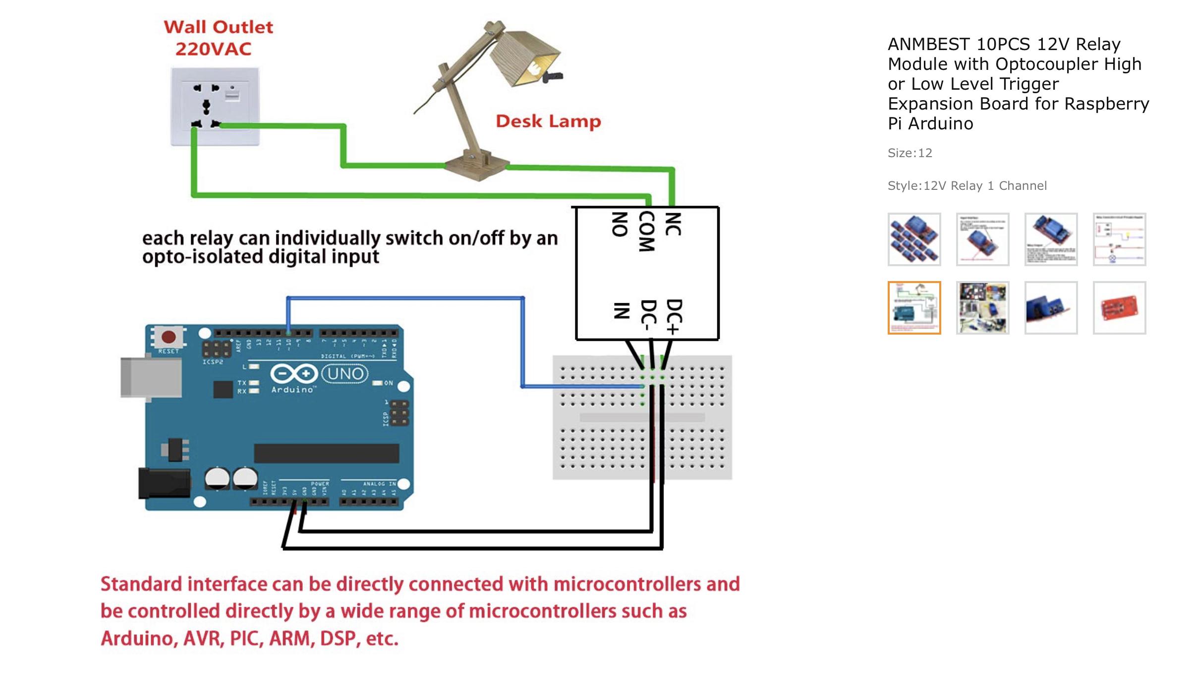
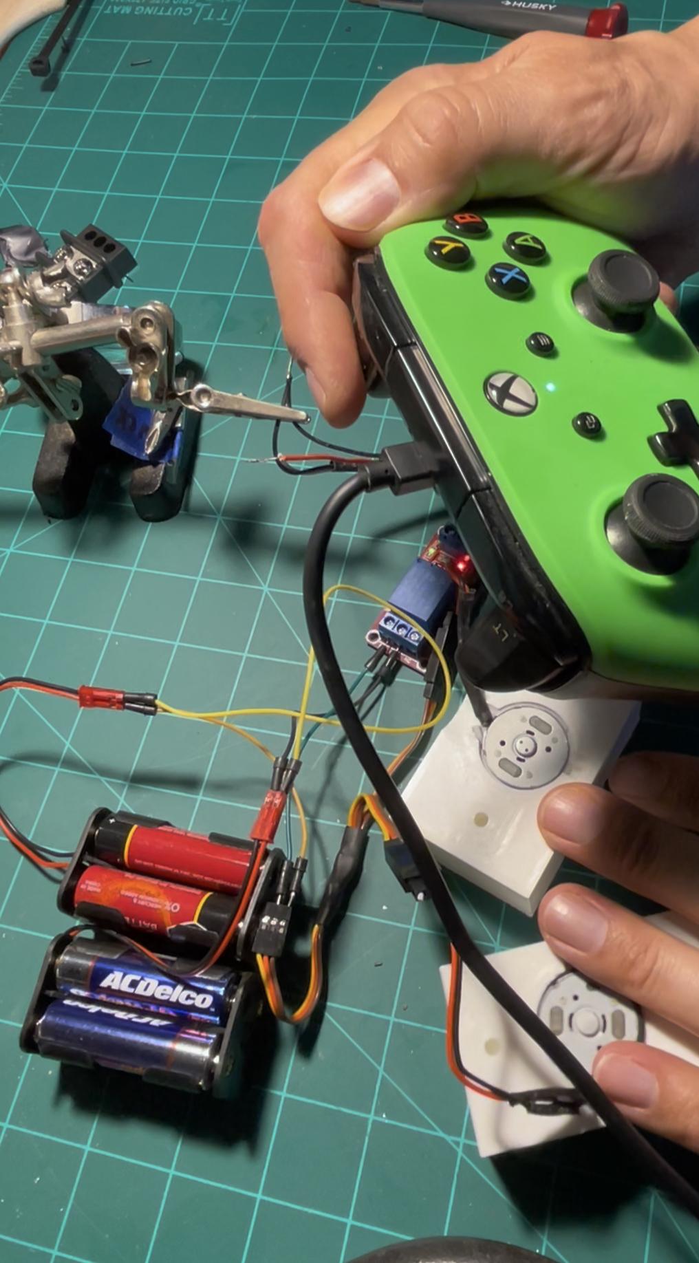
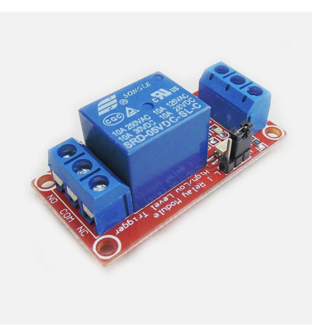
Relay switches are the hidden gems of the electronics world; with no more than 3.3v of input voltage you can operate/switch on/off a load of 250v! This Herculean feat is accomplished by using an internal electro-magnet as the actual switch to close the much larger load. This is explained in greater detail in the images supplied, and by the genius minds at https://theengineeringmindset.com/how-relays-work/. I have used these magnificent switches in many a project over the years from: drill-motor battle bots to large scale RC vehicles (a Mega-Power wheels upgrade). Be sure to follow the wiring diagram pictured above, as well as plug a jumper wire from the IN to DC- (negative, pictured as the red wire).
Wiring
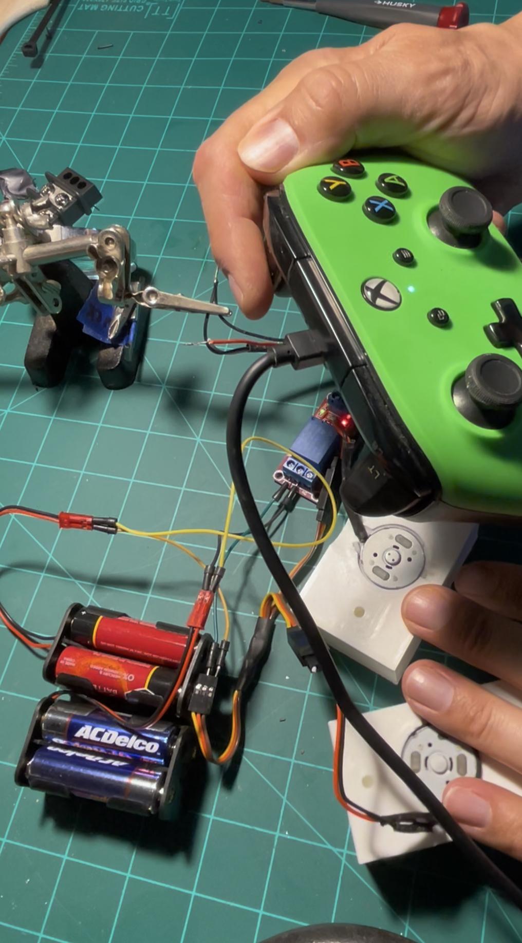


- Place your rumble motors into the printed rumble cubes
- Wire two rumble motors together, with the MALE servo wire plug out.
- Connect the two rumble motors to the Y servo plug
- Connect the jumper wires from the controller to the DC+ and DC- on the relay switch (FEMALE Servo plug)
- Connect the LOAD (the power packs and the rumble motors) to the NO and COM ports
- Plug your XBOX controller into your PC and run the Microsoft Controller Tester App. * Remember to choose vibration in the app to test your controller. *
Assemble the Awesomeness

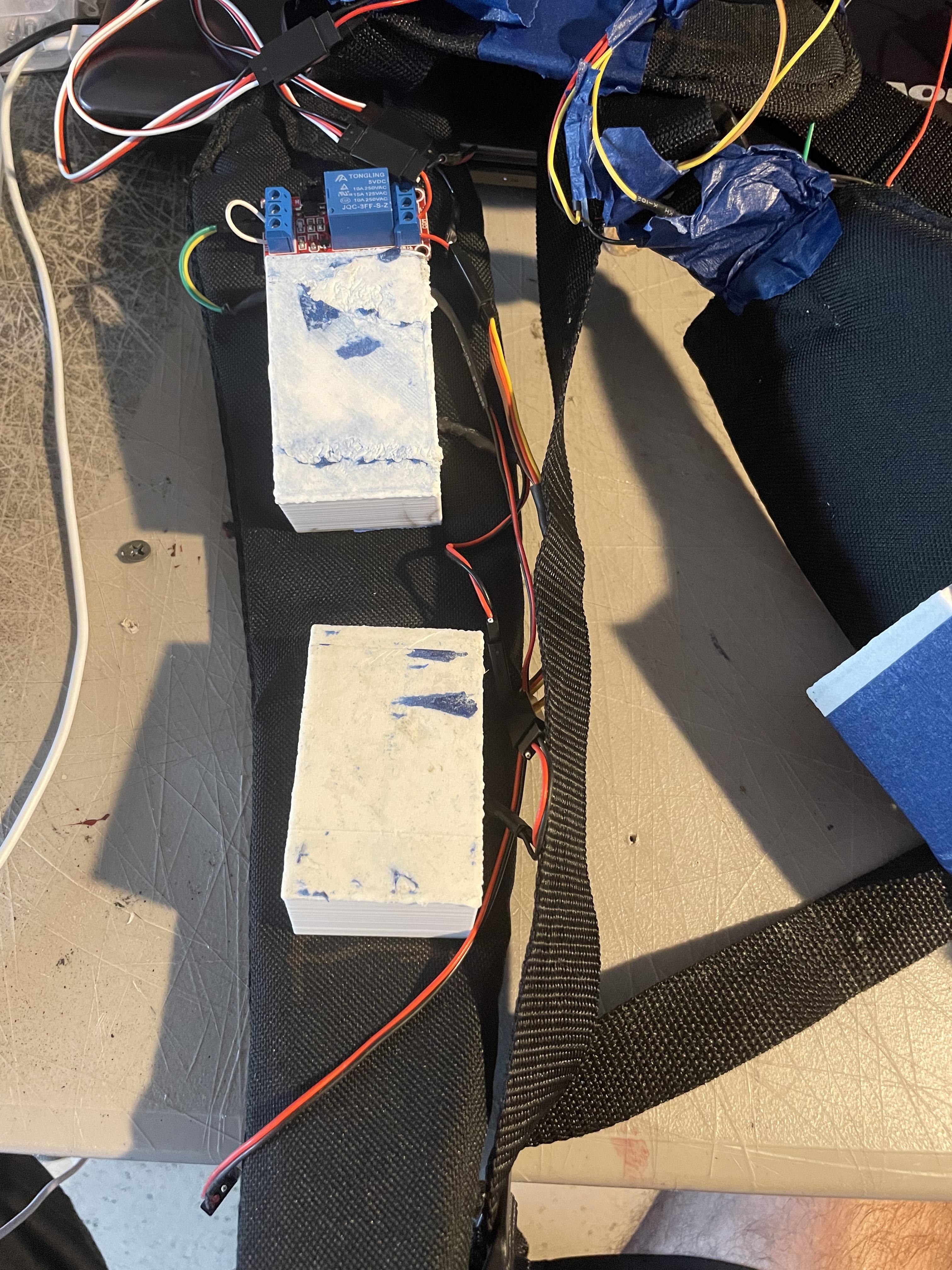


I have been working on this "Tooth-rattling" Version for the better part of the last two weeks. The technology involved isn't ground-breaking, or complex; I have used relays in the past to make RC power wheels vehicles, E-Scooters, and a handful of drill motor-powered battle bots.
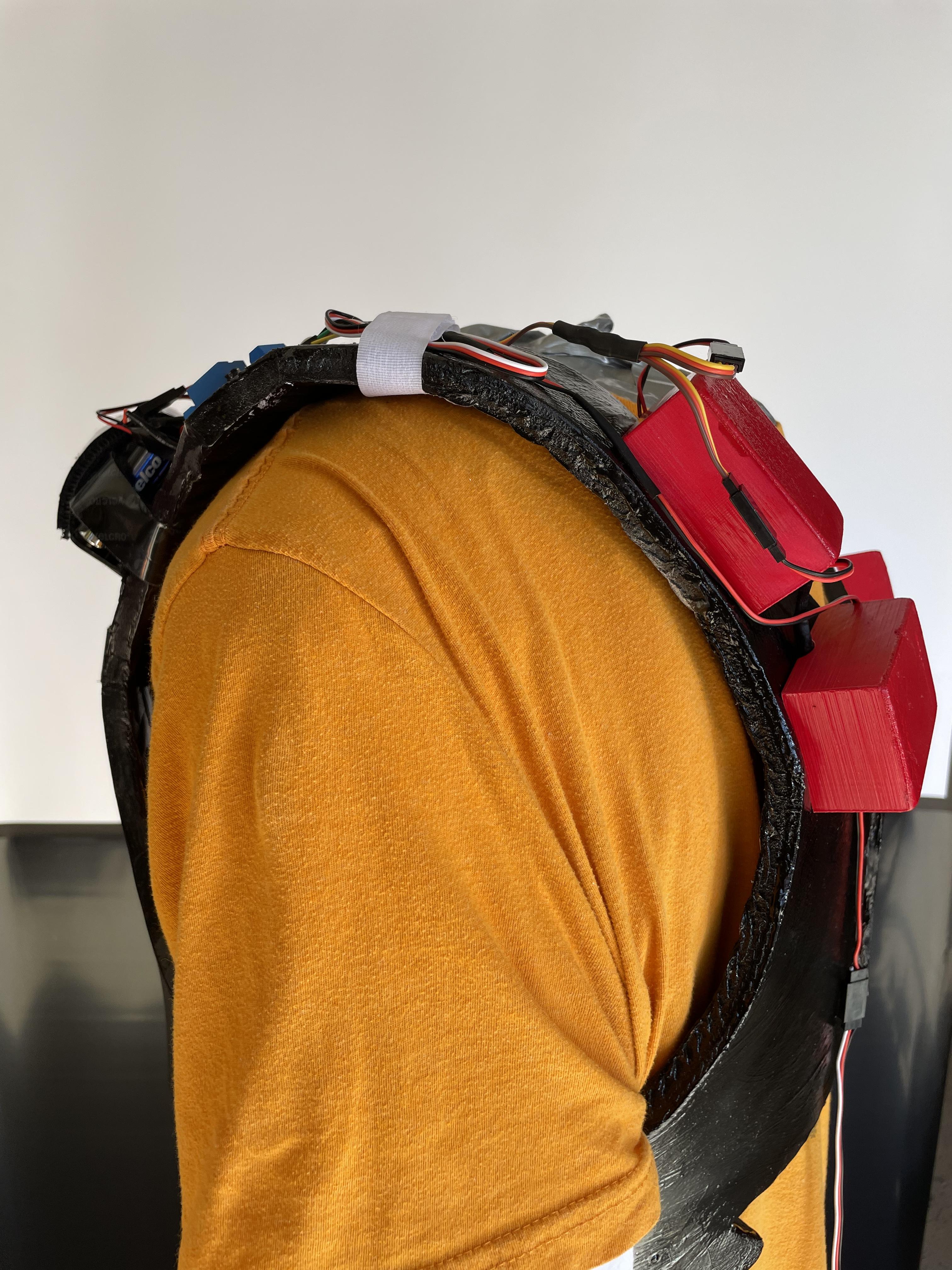
The short video above shows the relay that I chose to use on each side of the harness and the wiring to the relay (and the rumble motors) on that particular side. I increased the voltage to the rumble motors by attaching the battery packs negative-to-positive thereby doubling the output, and making the rumble motors vibrate out of the painter's tape that once held them to the shoulder straps. The new power output is upwards of 12 volts per two rumble motors, instead of the previous, varied, 3.3 volts. I especially enjoy the vest while playing the classic Street Fighter IV, OverWatch 2, and BurnOut.
The small cardboard box presented above was an Amazon box that I repurposed as a battery pack housing for the 16 AA batteries, which was Velcro strapped to the area of the harness on mobile my upper back.
The video above: I attached the rumble motors to the harness by first burning through chest straps with a soldering iron; the one-inch drywall screws were run through small washers to allow for more surface area on the back side of the straps (more grab, and lessening the likelihood of the screws pulling through the strap). Wires were trimmed, soldered, wrapped in heat shrink, and then Velcro was used to bind the wires to the straps.
The relay switches can be removed from the circuit by simply bypassing them and running the signal directly from the XBOX/PS3 controller; this was one of the benefits of using the more expensive servo wires, as they easy connection/disconnection.
In the future, I will be modifying this haptic vest (with and without relay switches) to make a "Spider-Sense Suit" that can help those with various disabilities have situational awareness through the use of a varied array of infrared, sound, and motion sensors.
I hope that you enjoy making (and using) this project.
Have Some Fun!


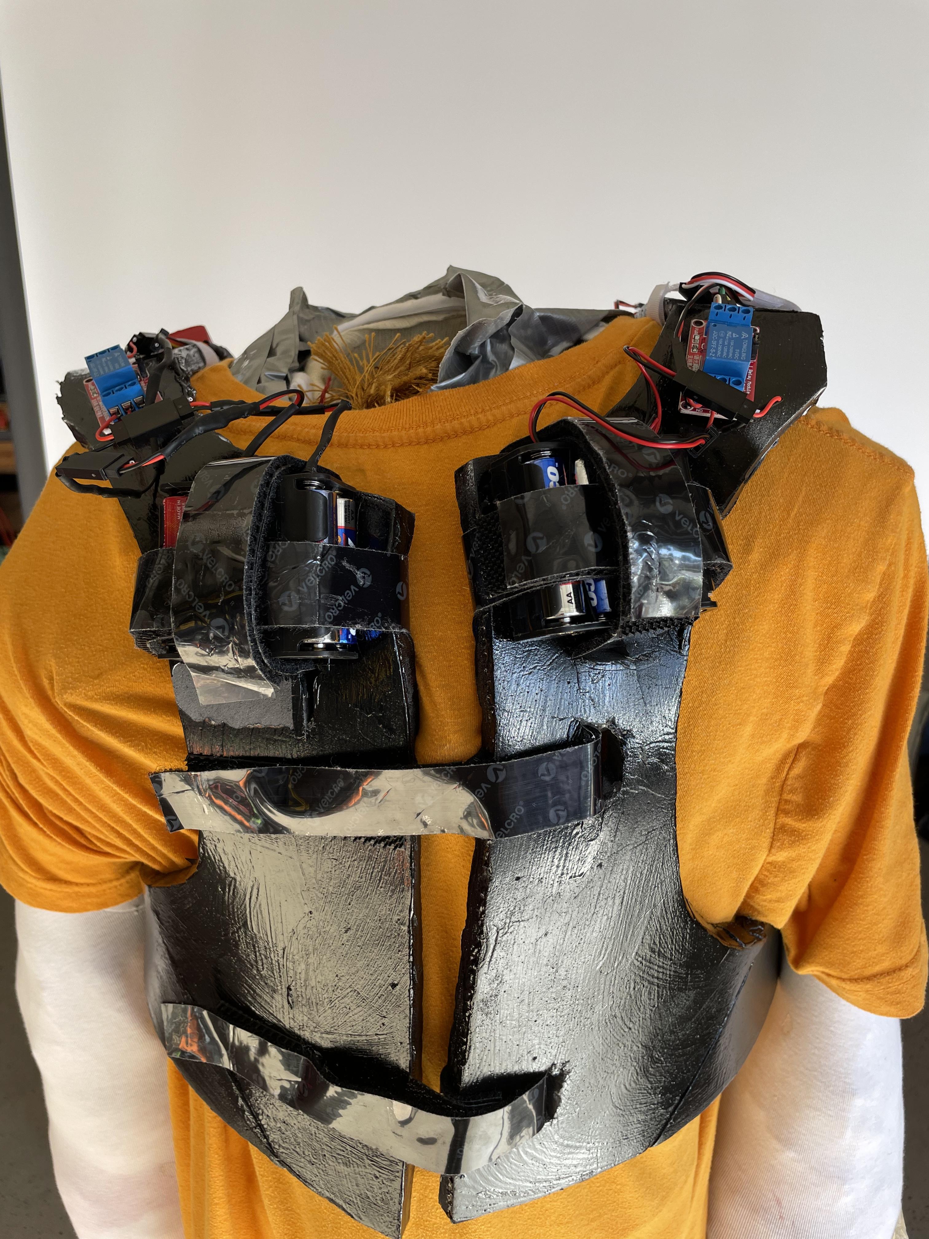

One of the greater benefits of this system is that the rumble motors are not slaves to only one console, if you have a controller that has a rumble feature then you can hack it and make it a part of this system.