Mega RasPi - a Raspberry Pi in a Sega Mega Drive / Genesis
by pedromauricio in Circuits > Raspberry Pi
3492 Views, 23 Favorites, 0 Comments
Mega RasPi - a Raspberry Pi in a Sega Mega Drive / Genesis
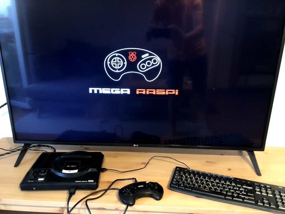
This guide takes you through the conversion of an old Sega Mega Drive to a retro gaming console, using a Raspberry Pi.
I have spent countless hours of my childhood playing video games on my Sega Mega Drive. Most of my friends had one too, so we would share games and organise tournaments amongst ourselves. Thirty years later, I have finally found a way to pay homage to those memories, by converting a Sega Mega Drive to a retro gaming console and media server that I can use everyday using a Raspberry Pi: the Mega RasPi.
My goal is to preserve as much of the console's original parts and functionality as possible, while making the RasPi itself easily accessible.
Supplies
- 1 faulty Sega Mega Drive (or Genesis)
- 1 or 2 working controllers, 3 or 6 buttons
- 1 Raspberry Pi 3B+
- 1 Micro SD card, RetroPie v4.5 pre-installed
- 1 ControlBlock v2.1
- 1 Power adapter, 5V 3A, with a 5.5mm / 2.1mm plug
- Raspberry Pi heatsink
- PLA 2.85mm filament
- Extension cables and wires:
- HDMI cable, 30 cm
- Ethernet cable, 30 cm
- 3x USB cables, 20/30 cm
- Micro SD card reader cable, 25 cm
- 3.5mm jack audio cable
- Micro USB power cable
- Jumper wires, 25 cm
- Screws
- Optional
- 2.5 inch storage drive
- SATA to USB cable
Tools and Resources
- Basic tools: screwdrivers, pliers, saw, etc.
- Soldering iron and supplies
- 3D printer
- Basic knowledge on 3D printing, soldering and linux tools
Disassembling the Mega Drive
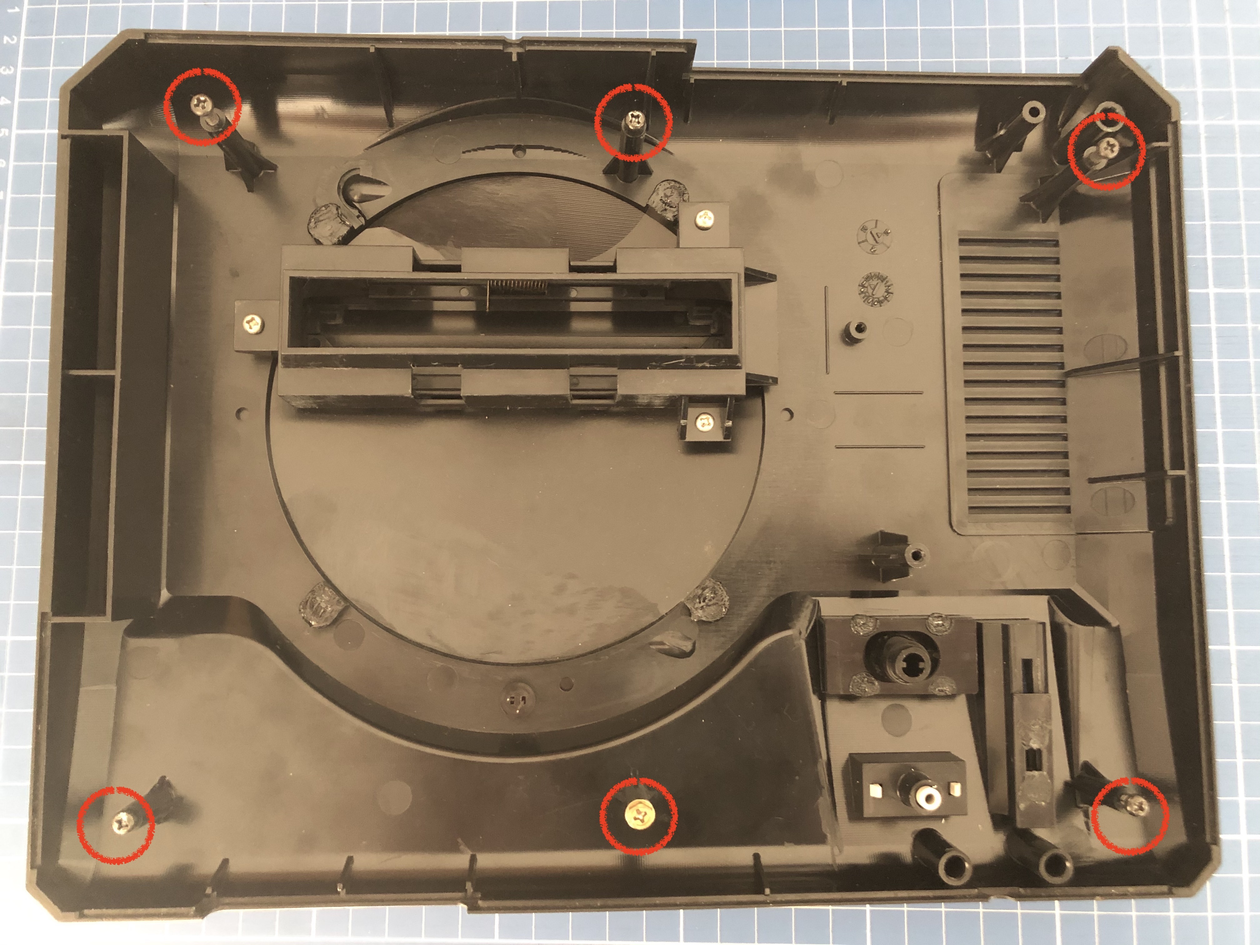
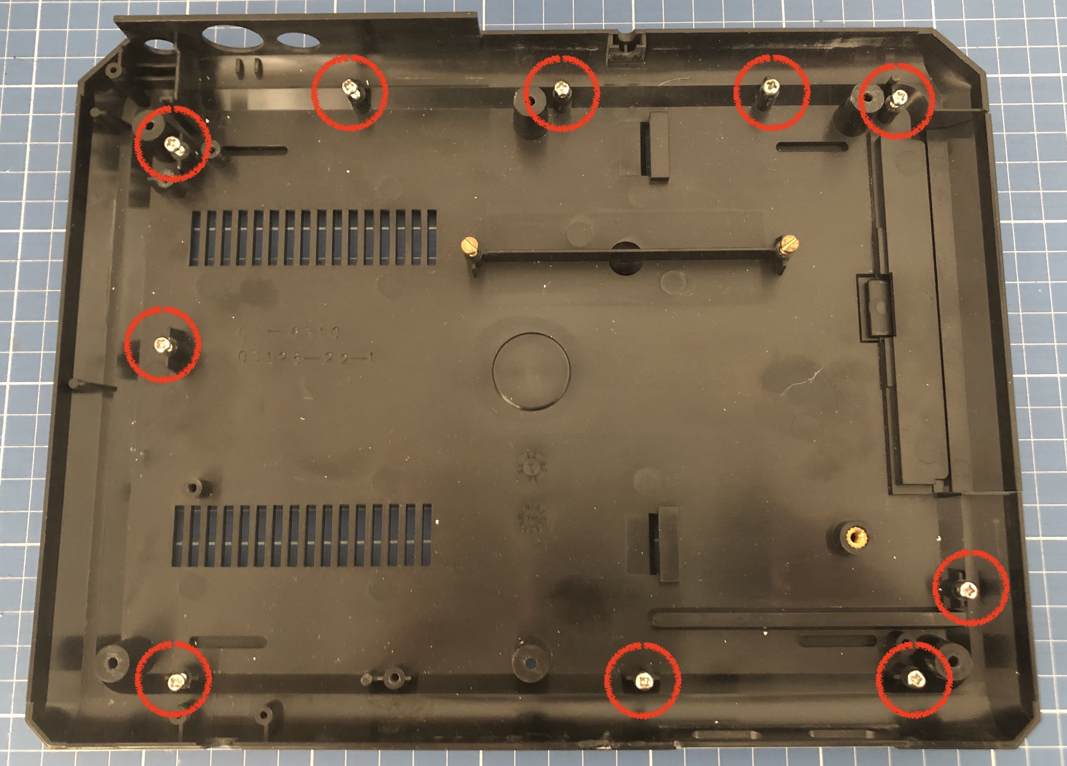
No fancy tools required for disassembly: a good old-fashioned screwdriver is enough.
There are 6 screws to open the outer case, and 10 more to remove the board. Some of them are of different length though, keep track of which one goes where.
A note on the model: There's a few different models with slightly different port configurations. The one used for this guide is 1601-18.
3D Printing New Parts
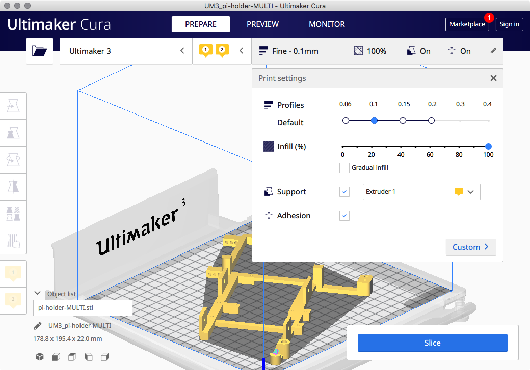
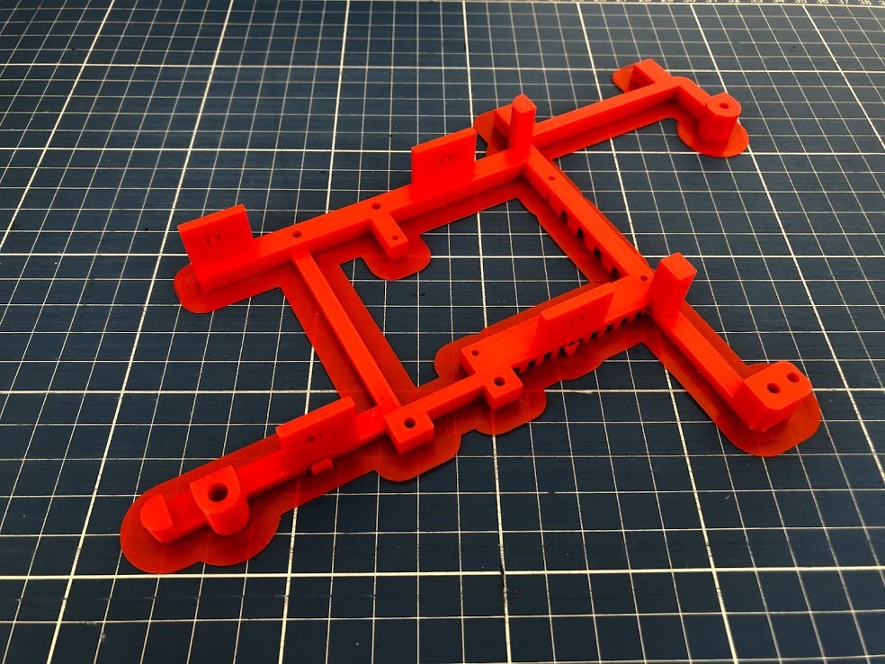
I wanted the new pieces to really stand out, so I used red filament, with the following configuration on Ultimaker Cura:
- Printer: Ultimaker 3
- Filament: PLA 2.85 mm
- Resolution: 0.1 mm
- Infill: 100%
- Support and Adhesion both checked
You can find the source .stl files from Sega Mega Drive 1 with Raspberry Pi 3 things.
Print the following:
- Back ports: HDMI and Ethernet
- back-1-HDMI-1601-18.stl
- back-2-HDMI-1601-18.stl
- back-1-HDMI-1601-18.stl
- Side extension slot: USB and Micro SD card reader
- slot-1-D-SUB.stl
- slot-2-D-SUB.stl
- slot-3-D-SUB.stl
- Internals
- pi-holder-MULTI.stl
A note on 3D printing: PLA is a common and easy material to work with, however you could consider other materials for stronger pieces, eg: PETG
These files are part of this fantastic conversion project and it's really well documented with detailed instructions. The author sells the complete kit on his website, you might want to check that out too.
Back Ports: HDMI and Ethernet
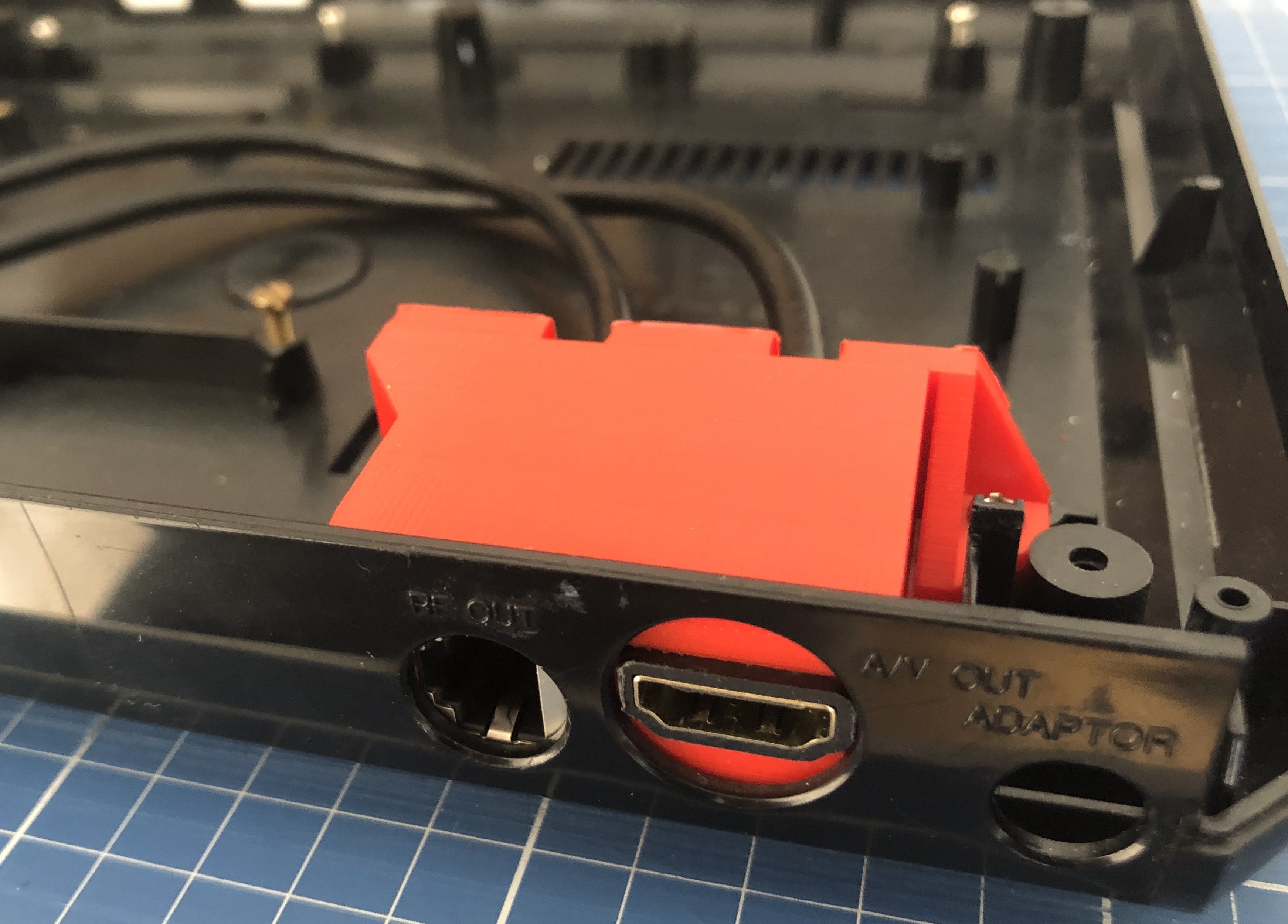
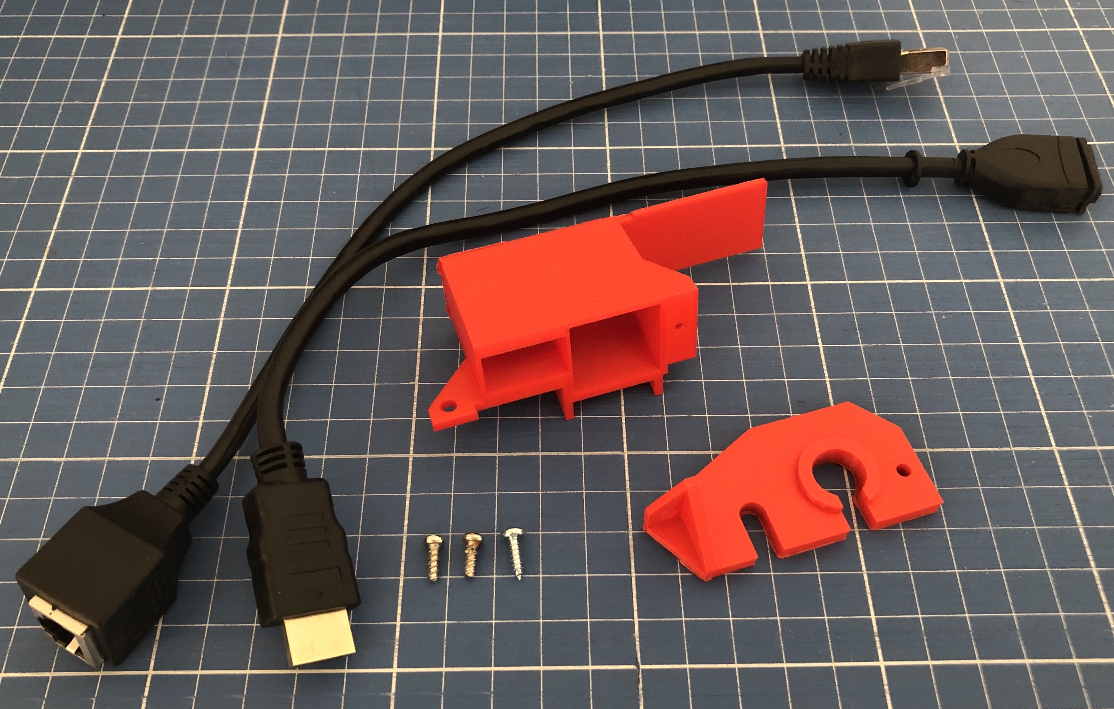
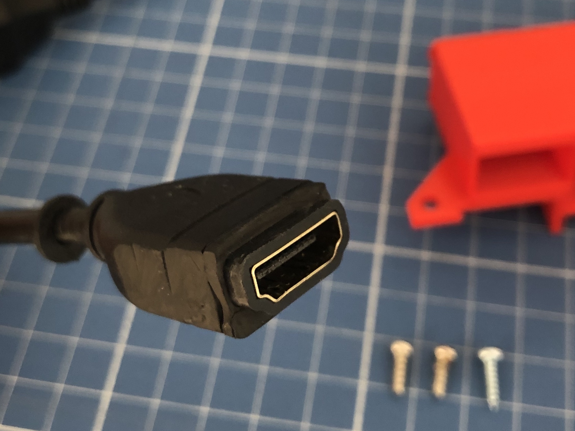
Grab both back-1-HDMI-1601-18 and back-2-HDMI-1601-18, together with the HDMI and Ethernet extension cables. You will also need 3 screws.
Once both cables are in place, screw the support to the bottom case.
A note on sourcing the right cables: It's not easy to find cables that fit the supports perfectly. My advice is to visit a couple of electronics shops and try out some cables until you find something that fits.
You may need to carve some of the parts to fit them into the supports. That's what I did with the HDMI cable, as you can see in the photos. It shouldn't be a problem, as long as you stick to basic cables with rubbery plugs, especially if ordering online
The alternative would be to edit the .stl files and print custom supports for the right cables.
Side Extension Ports: USB and MicroSD
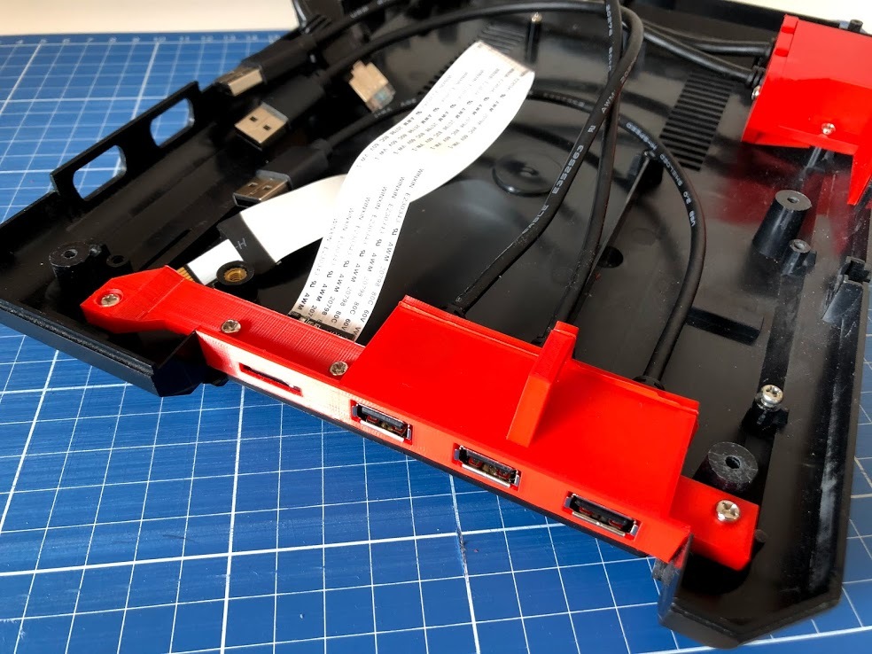
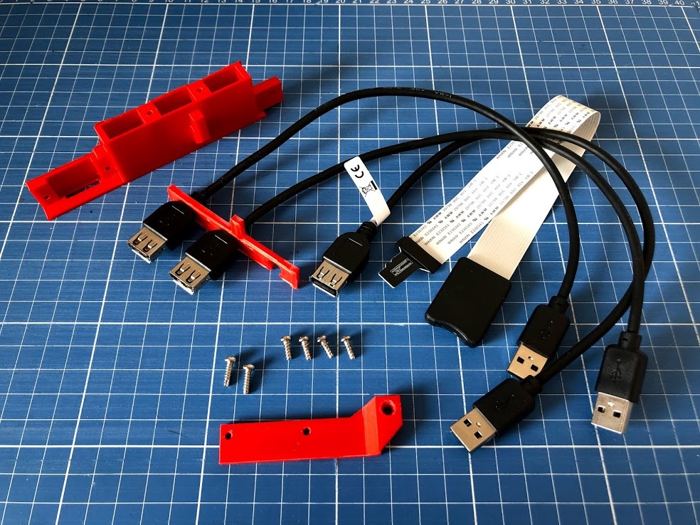
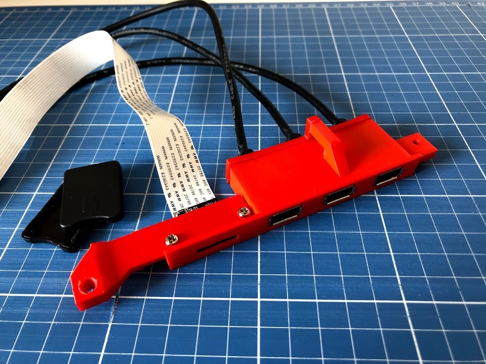
Grab slot-1-D-SUB, slot-2-D-SUB and slot-3-D-SUB, as well as the USB and Micro SD card reader extension cables. You'll also need 4 screws. Mount all the cables into the support and then attach it to the case.
A note on USB versions: all four USB ports in Pi 3B+ are version 2.0. However, Pi 4 offers two USB 3.0 ports. Keep that in mind to get correct cables and keep compatibility.
Trimming and Soldering the Board
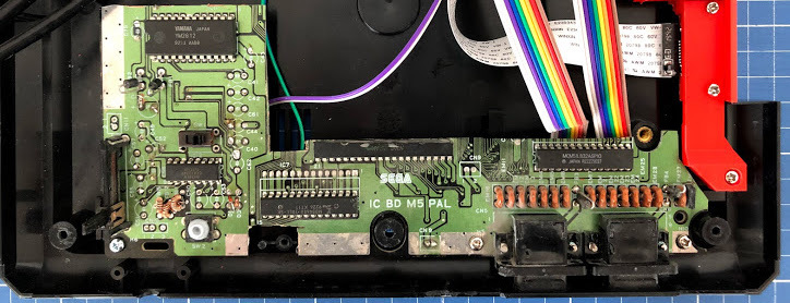

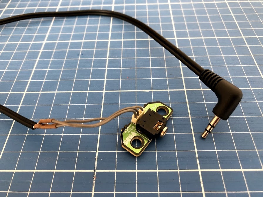
Trim the board to fit in the case with the new 3D printed supports, while keeping the original buttons and controller ports as shown in the photo. Keep the audio and power jack as well.
Solder all necessary wires to the correct terminals (see photos):
- Power switch, 2 jumper wires
- Reset button, 2 jumper wires
- Controller ports, 9 jumper wires per port
- Power jack, power cable with Micro USB
- Audio jack, audio cable with 3.5 mm jack
Once this is done, attach the circuit to the bottom case with 3 screws.
A note on board alterations: I really like the idea of integrating original and new components as a homage to the original console and make old parts useful, inspired by this project. However, don't do this with a functional Mega Drive! Preserve it and find a broken one instead. You can probably find a cheap one off eBay.
Installing and Cooling the Raspberry Pi
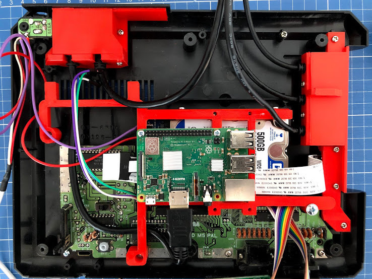
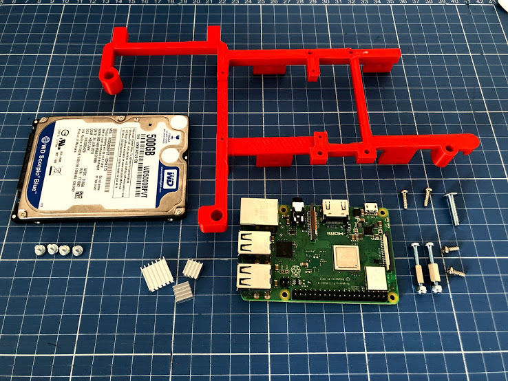
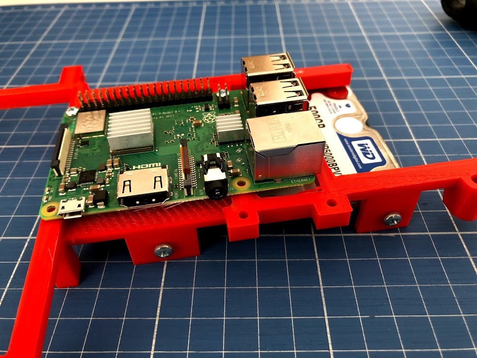
Grab pi-holder-MULTI, together with the Raspberry Pi and (optionally) the 2.5" storage drive (more details on this in the next step)
Stick the heatsinks to the Pi, and attach the Pi to the support. It starts to get tricky to mount everything with the cables, so keep an eye on that.
A note on cooling: I have only passive cooling, to keep the system silent. I placed some heatsinks on the CPU, RAM and USB/Ethernet chips. To install active cooling, you will need to print the fan-holder-MULTI and attach a cooling fan, mountable on the top case. Refer to the original project for details.
(Optional) Adding a Storage Drive
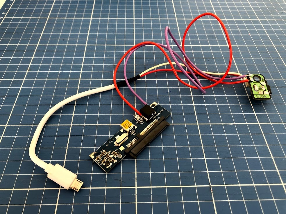
If you chose to add a storage drive, a main considerations to take into account is power. It's very likely that the USB port won't be able to provide enough power.
As an experiment, I used an old HDD with parts from an external case, which can be powered independently. The HDD is then connected in parallel to the same jack as the RasPi - as you can see in the photo.
The result is a bit messy, and there's a lot of unnecessary components here. I'd suggest a dedicated SATA to USB cable instead, with a dual USB port for independent power.
Installing ControlBlock: Controllers, Power Switch and LED
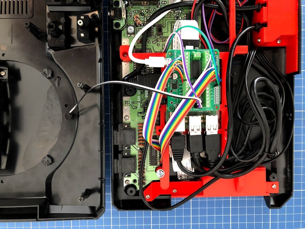
Connect the power switch and controllers to the ControlBlock. This is fairly straightforward, as the controller pins 1 through 9 are connected sequentially. Attach the LED on the top case with two additional jumper wires as well, keeping the correct polarity.
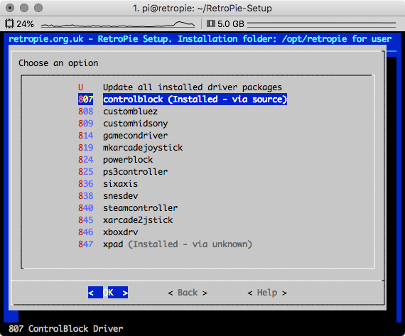
The ControBlock snaps right on top of the RasPi, though the driver must be installed to make it functional.
Install the driver
Open RetroPie Setup menu and install the driver via the menu:
RetroPie-Setup > Manage packages > Manage driver packages > controlblock > Install
Configure controller type:
On a terminal, type:
sudo nano /etc/controlblock.cfg
Find gamepadtype and change it to genesis.
...
	"gamepadtype" : "genesis",  // Sets the gamepad type. Options: "arcade", "mame", "snes", "nes", "genesis", "none"
...
You should now be able to setup the controllers in RetroPie.
For further detailed instructions and configuration, see ControlBlock2 documentation.
A note on the ControlBlock v2.1: this component adds power management and controller support to the Raspberry Pi. The power management prevents data corruption and the controller adds support for original controllers. Modern controllers can still be used with one of the side USB ports or via Bluetooth.
Even though this component is convenient, you don't really need it to complete this project. The power switch could be connected directly to the Raspberry Pi, and the controllers plugged to the GPIO using db9_gpio_rpi.
Reset Button
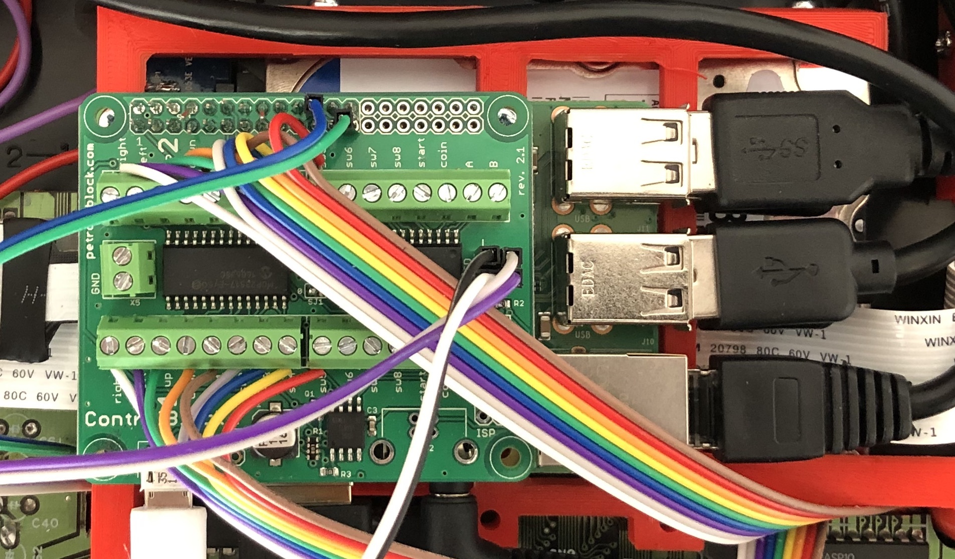
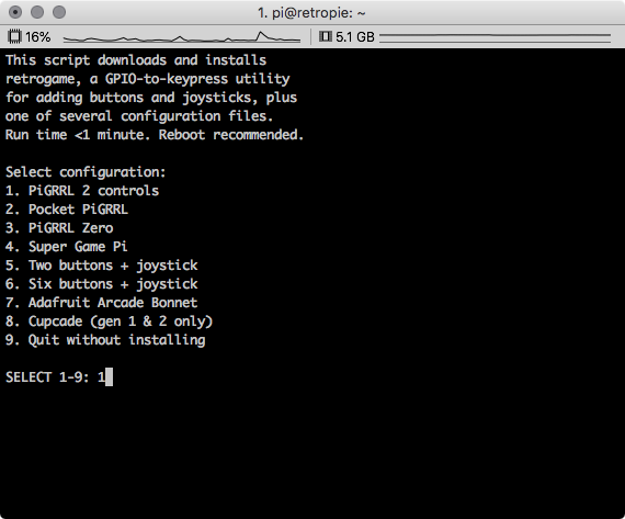
The reset button is configured to quit any emulator and go back to the game selection menu.
Install PiGRRL2 Controls
On a terminal, type:
curl -O https://raw.githubusercontent.com/adafruit/Raspberry-Pi-Installer-Scripts/master/retrogame.sh
sudo bash retrogame.sh
Select option 1: PiGRRL 2 controls and let the script complete the installation.
Change the ESC pin configuration
Since the default pin used for ESC conflicts with ControlBlock, we need to change it to a different pin, eg: GPIO 25 (pin 22)
sudo nano /boot/retrogame.cfg
Find the ESC key line, and change it to 25:
...
	ESC       25  # Exit ROM; PiTFT Button 1
...
Update RetroArch
On a terminal, type:
sudo nano /opt/retropie/configs/all/retroarch.cfg
Find the input_enable_hotkey and input_exit_emulator and change both to "escape"
...
	input_enable_hotkey = "escape"
...
	input_exit_emulator = "escape"
...
Connect the Reset button
Finally, connect the reset button jumper wires to pin 22 (GPIO 25) and pin 25 (Ground).
A note on PiGRRL 2: This is an entire different project in itself, and we are using only one of the many features provided by it. The Reset button is simply configured as the Esc button behind the scenes.
Volume Control (Not Tested)
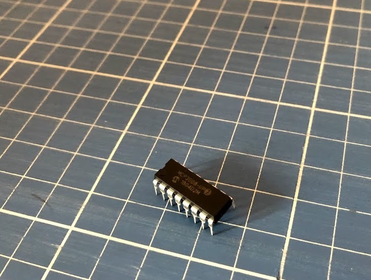
This step is not completed in this guide!
Unfortunately, the volume slider potentiometer on my Mega Drive was broken and I couldn't connect it to my RasPi. However, it is possible to control the sound volume on the Rasperry Pi using a potentiometer. Even though I can't provide detailed instructions, I'd encourage you to experiment with it a bit.
The analog signal from the potentiometer must be converted to a digital signal that the Raspberry Pi can read, which can be achieved using an MCP3008 chip connected to the GPIO.
Have a look a the following guide for step-by-step instructions:
Power Supply
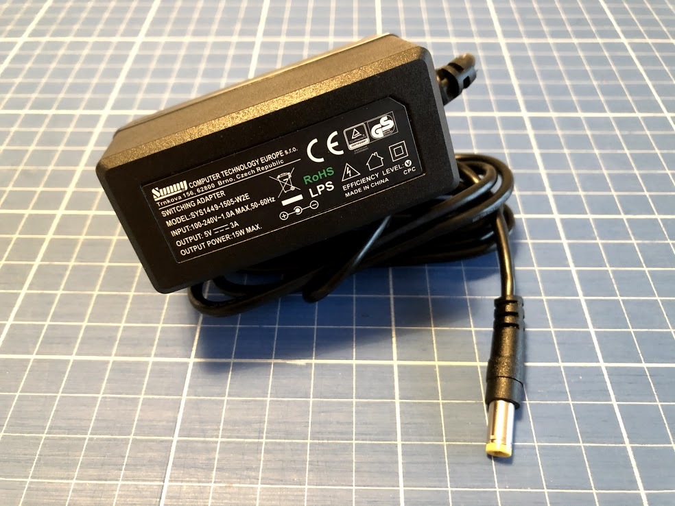
Here, I also kept the original power jack, however you'll need an appropriate power source for the job, especially if you also added the storage drive.
Pay attention to the polarity of your new power source. The Mega Drive power jack is wired with positive on the outside of the plug. However, it's a lot more common to find power sources with ground on the outside. Make sure you wire everything correctly.
Reassemble the Case
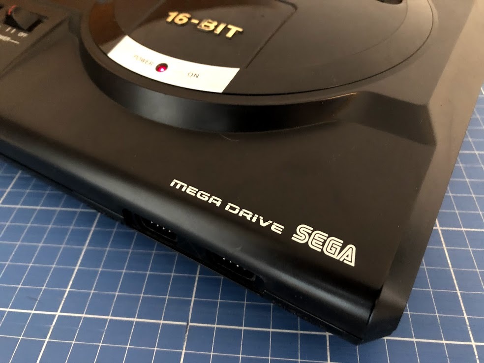
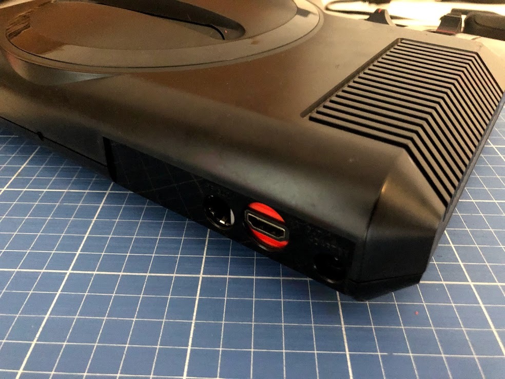
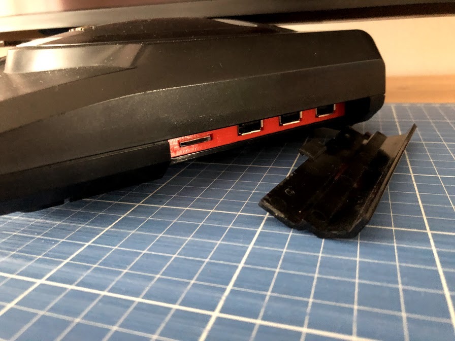
The hard work is done, now it's time to put everything together. It gets tricky with all the cables, but everything should fit. Screw the top and bottom cases together with the 6 original screws.
Plug It in and Enjoy

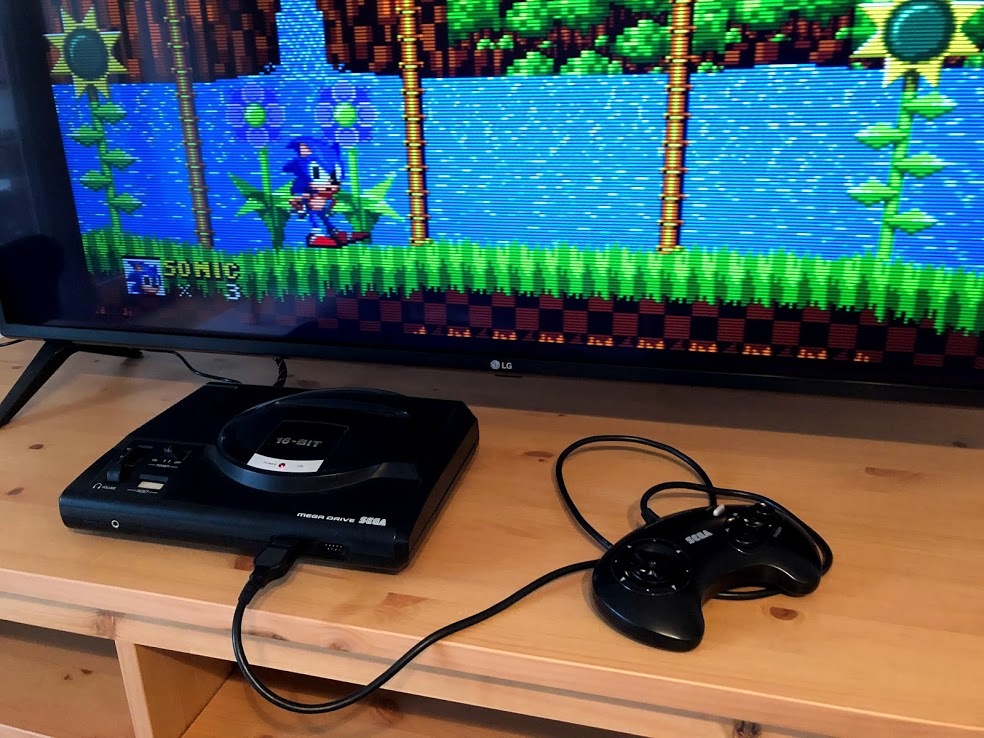
Plug everything in: HDMI, Controller and Power and flip the switch on. If you haven't done it earlier, the controllers need to be configured in RetroPie, in order to be usable.
Splashscreen
As a bonus, I've attached a splashscreen that you can use on your own Mega Raspi. To use it, upload the image to:
/home/pi/RetroPie/splashscreens/
Then change the Splashscreen configuration, under the RetroPie menu.
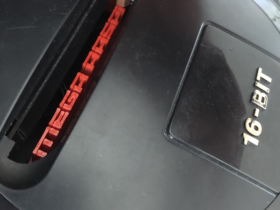
Cartridge slot easter egg
After re-purposing the console I felt the cartridge slot was left abandoned. Therefore I'm also making available a Mega RasPi logo to be 3D printed and placed under the cartridge slot, to be revealed only when you open the little slot gates.
Now it's time to enjoy the Mega RasPi with your favourite retro games. Have fun!