Mechanical Xylophone
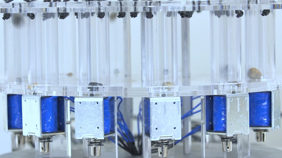
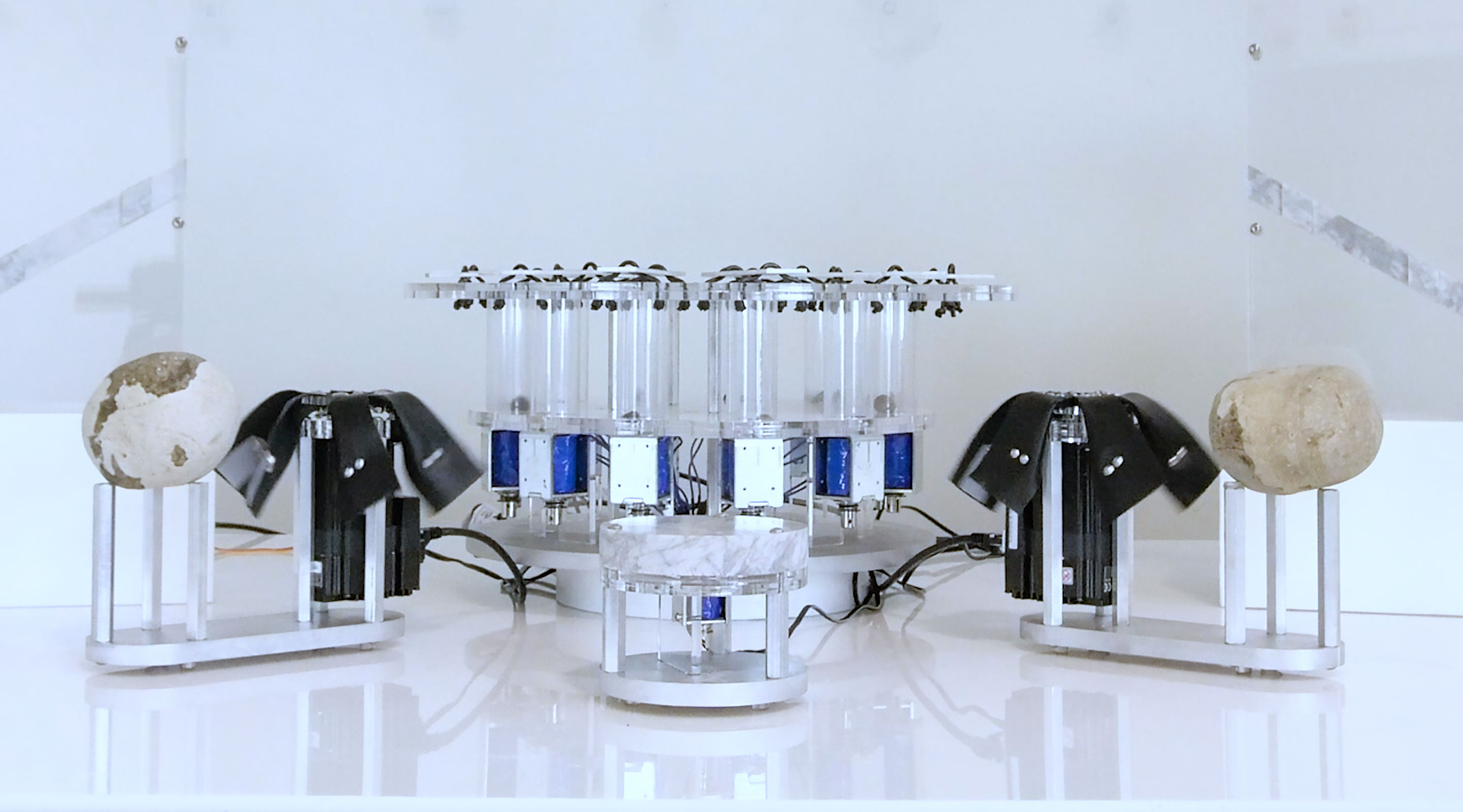
This Instructable will actually show you how to make a mechanical glockenspiel as the keys are metal rather than wood (xylophone is a far better word though featuring very underused letter X). This instrument was a part of The Rock Band, composed of instruments that make music with rocks by throwing them through the air, slapping them and making them vibrate. The project was created at Autodesk's awesome Pier 9 digital fabrication workshop as part of their artist in residence program.
The rock parts of this instrument are the small pebbles that are launched at the keys. However, any small hard object would probably work. The aluminium keys were fabricated using a water jet cutter. If that tool is not available to you, then wooden keys could be used instead provided that the rest of the design is updated to accommodate their design. The xylophone will be controlled by MIDI so it is possible to control it to using most common music composition software, e.g. Logic, Cubase or Ableton.
Gather Materials

For this Instructable you will need the following materials...
- 12 x Pebbles: This instrument was a part of The Rock Band, composed of instruments that make music with rocks by throwing them through the air, slapping them and making them vibrate. You could also substitute this with any other small hard object.
- Rubber cord: Black Hollow Rubber Cord 4mm Round - Amazon
- 12 x Solenoids: I used JF-1250B solenoids ordered from China. They are also available on Amazon for a higher price.
- 24 x 12mm Inner Diameter O-Ring: Amazon
- Aluminium 0.125" for Keys, 18" x 8"
- Aluminium 0.5" for Base, 16" x 16": The base could also be made from acrylic or plywood.
- 2 x Clear Acrylic 0.25" (0.236"), 36" x 24": This could be made from plywood.
- 8 x Aluminum Female Threaded Hex Standoff, 3/8" Hex, 3-1/2" Length, 10-32 Thread Size: McMaster
- 12 x RFP30N06LE MOSFETs: Sparkfun
- Polycarbonate Tubing 1 1/2" OD: Amazon
- 12 x 10K Resistor
- 12 x 1N4004 Diodes
- Teensy 3.2
- 8 x 7/8" 10-32 screws
- 4 x 1" 10-32 studs
- Sticky Feet
- Speaker Cable
- Heat Shrink for Speaker Cable
- 12 x M3 x 6 Screws
- 12 x M4 Nyloc Nuts
- Blue Tape (UK Translation: Masking Tape)
- 12V Power Supply: Amazon
- Perfboard/Breadboard: I recommend soldering everything to perf board but I didn't get around to doing that before this Instructable so pics are of breadboarded version.
- Hookup Wire
- 2 x 12 Terminal Blocks
Generate Key Geometry
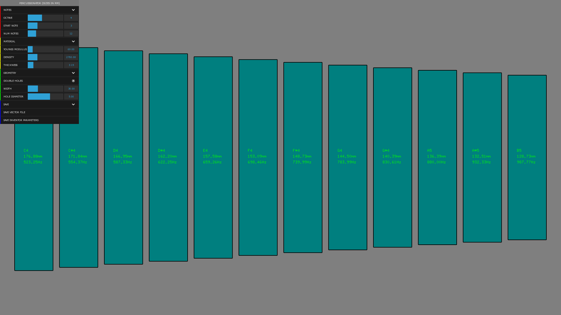
To generate the key geometry, I created a piece of software that takes material properties and various other configuration parameters and generates a vector file that can be used to cut the keys out either using a machine or to create a printable template. You can download an OS X version of the Xylo Master 5000 here.
The default setting are the ones used to design the CAD files with. If you change the settings, the size of the keys will change and you will also need to update the CAD files in the next step. The Xylo Master 5000 allows you to "SAVE INVENTOR PARAMETERS" that gives you an XML file that can be imported into Inventor.
Update Inventor Files

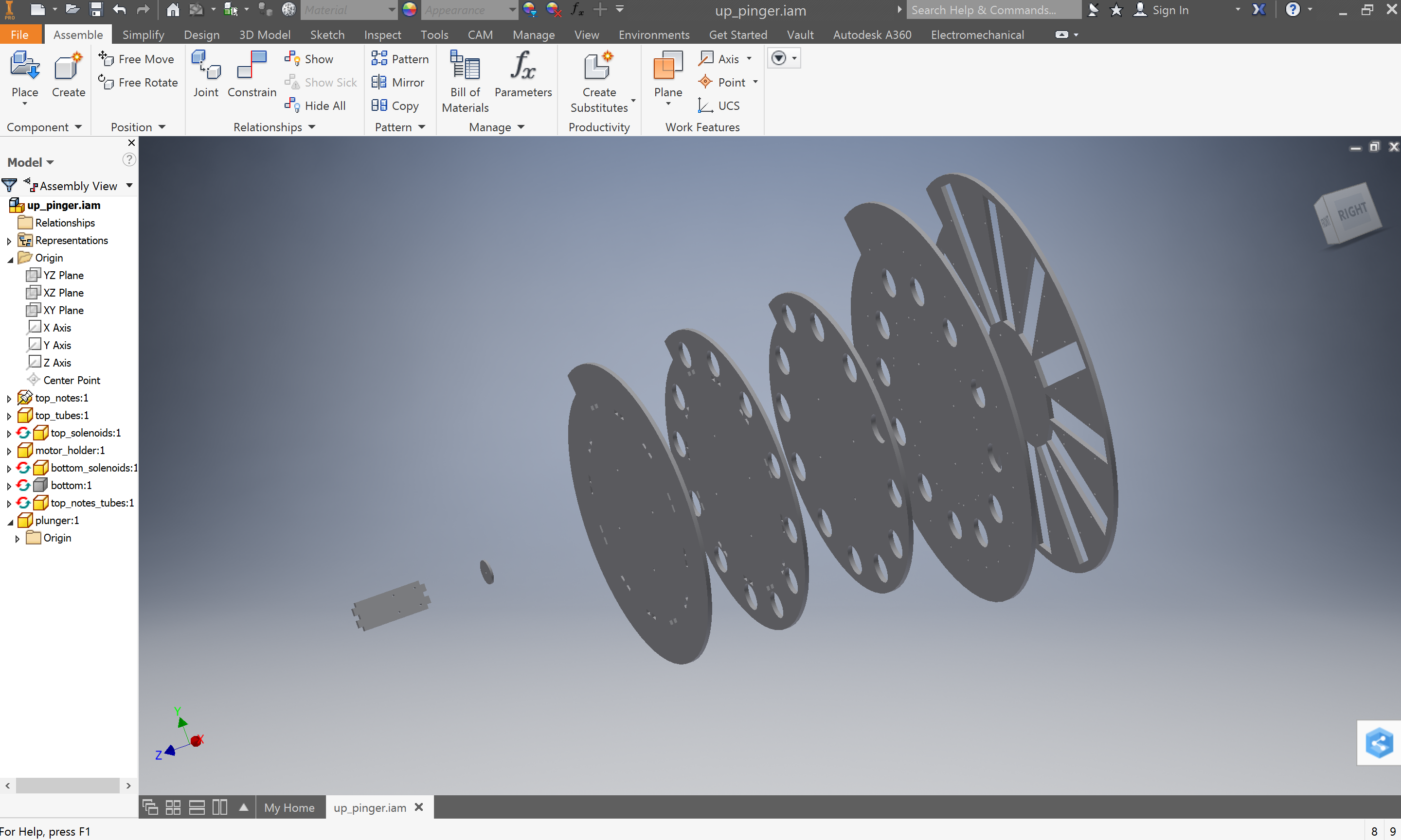
The CAD for the xylophone was done with Autodesk Inventor. I've included all the Inventor files here so you can make any changes you want. If you changed the notes at all in the previous step then you will need to update the top_notes.ipt file. You can import the XML parameters you exported in the previous step in the Manage tab => Parameters dropdown => Import from XML. This will then have
Waterjet Keys
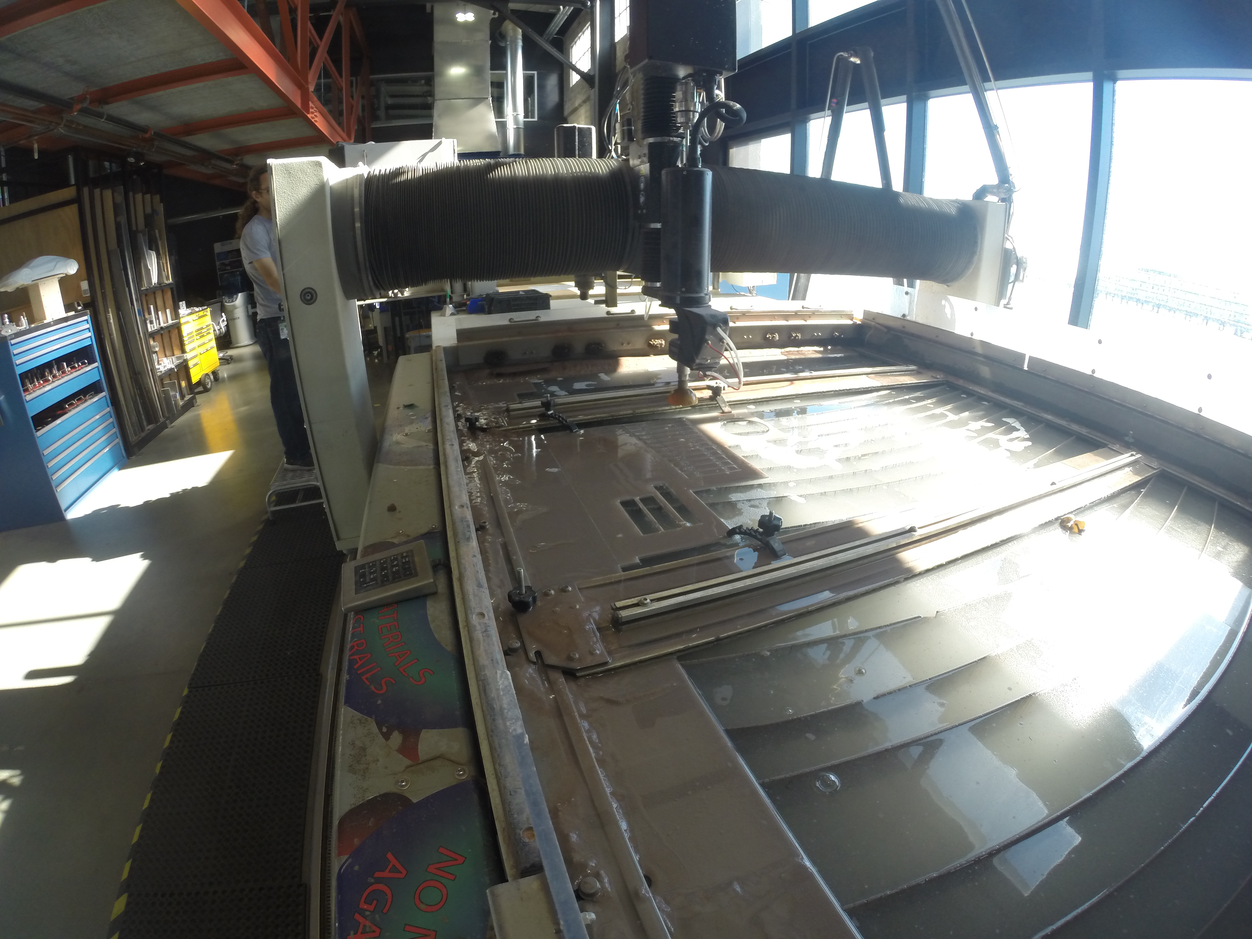
In this step, we'll use an waterjet cutter to fabricate the keys. I used an Omax waterjet cutter. You will need to amend the steps as appropriate if you have a different type of waterjet cutter.
Parts:
- Aluminium 0.125" for Keys, 18" x 8"
Steps:
- Import dxf files into Omax Make. Clean up file, move to appropriate location and set quality.
- Open file exported from Omax Make in Omax Layout, set the material parameters and if your machine has taper compensation then enable this.
- Clamp material to water jet bed.
- Zero the three axes using a suitable location to allow both cuts to fit on the same sheet.
- Press start and watch the metal cutting magic happen.
Downloads
Waterjet Base
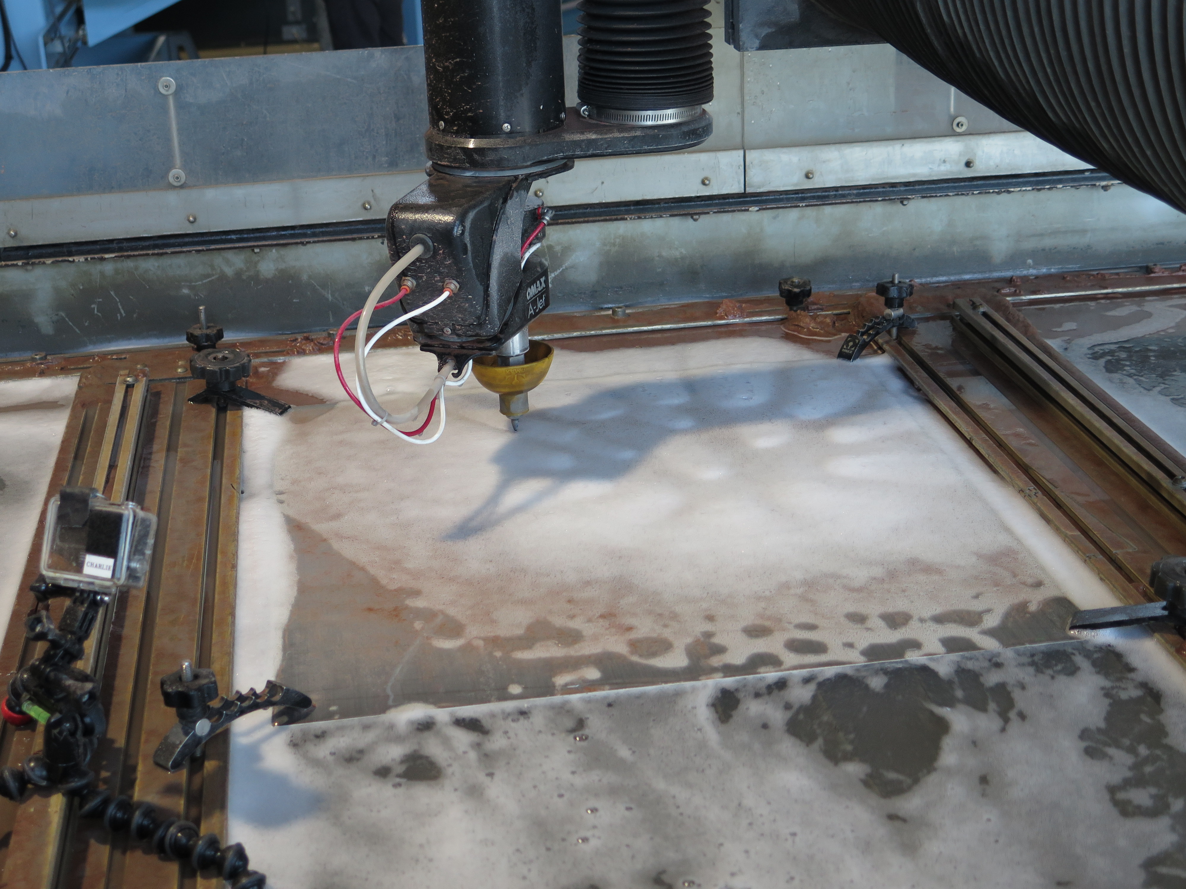
In this step, we'll use an waterjet cutter to fabricate the base...
Parts:
- Aluminium 0.5" for Base, 16" x 16"
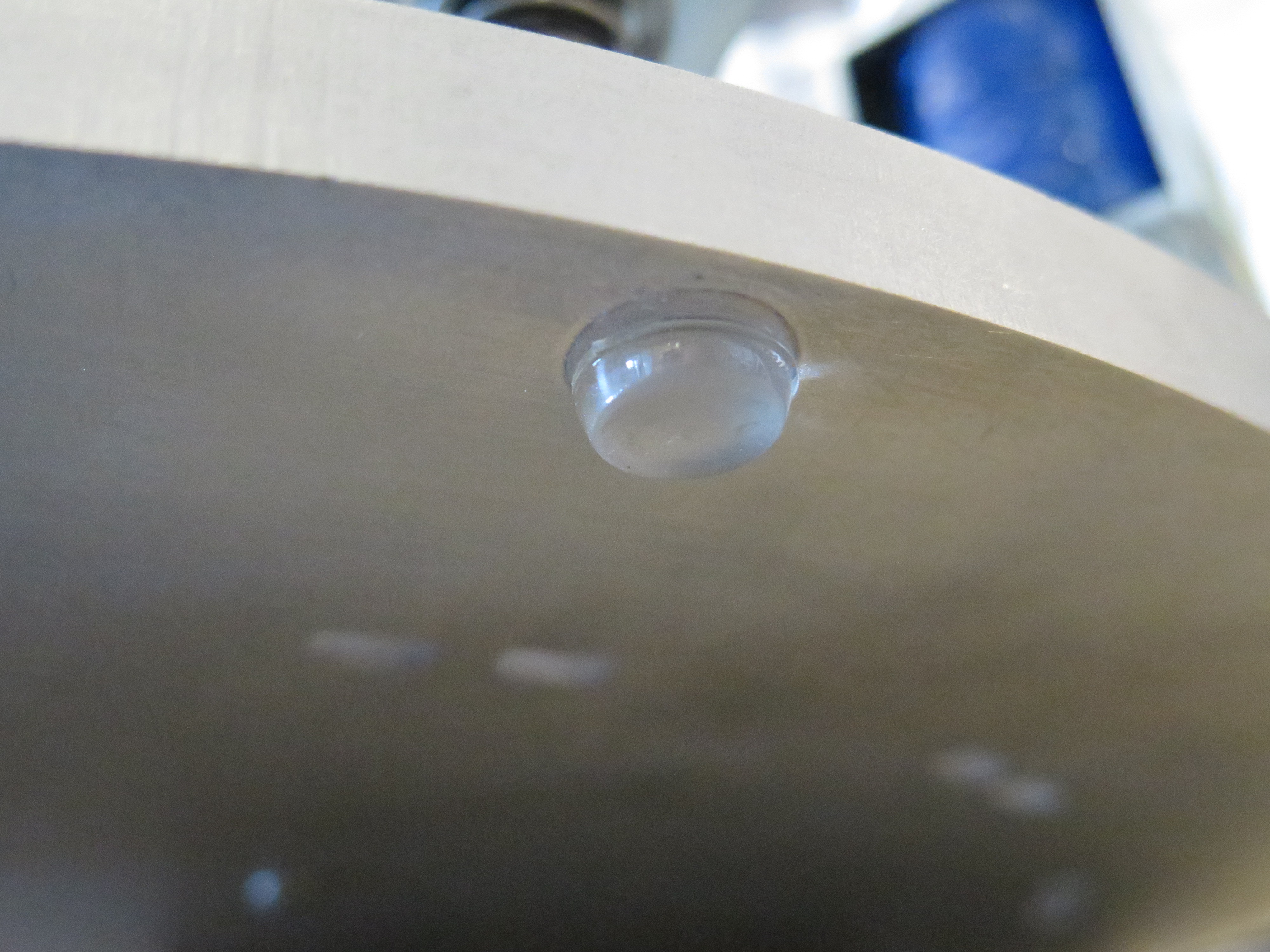
- Sticky Feet
Steps:
- Follow instructions from previous step.
- Stick on feet
Downloads
Laser Cut Acrylic Components
Parts:
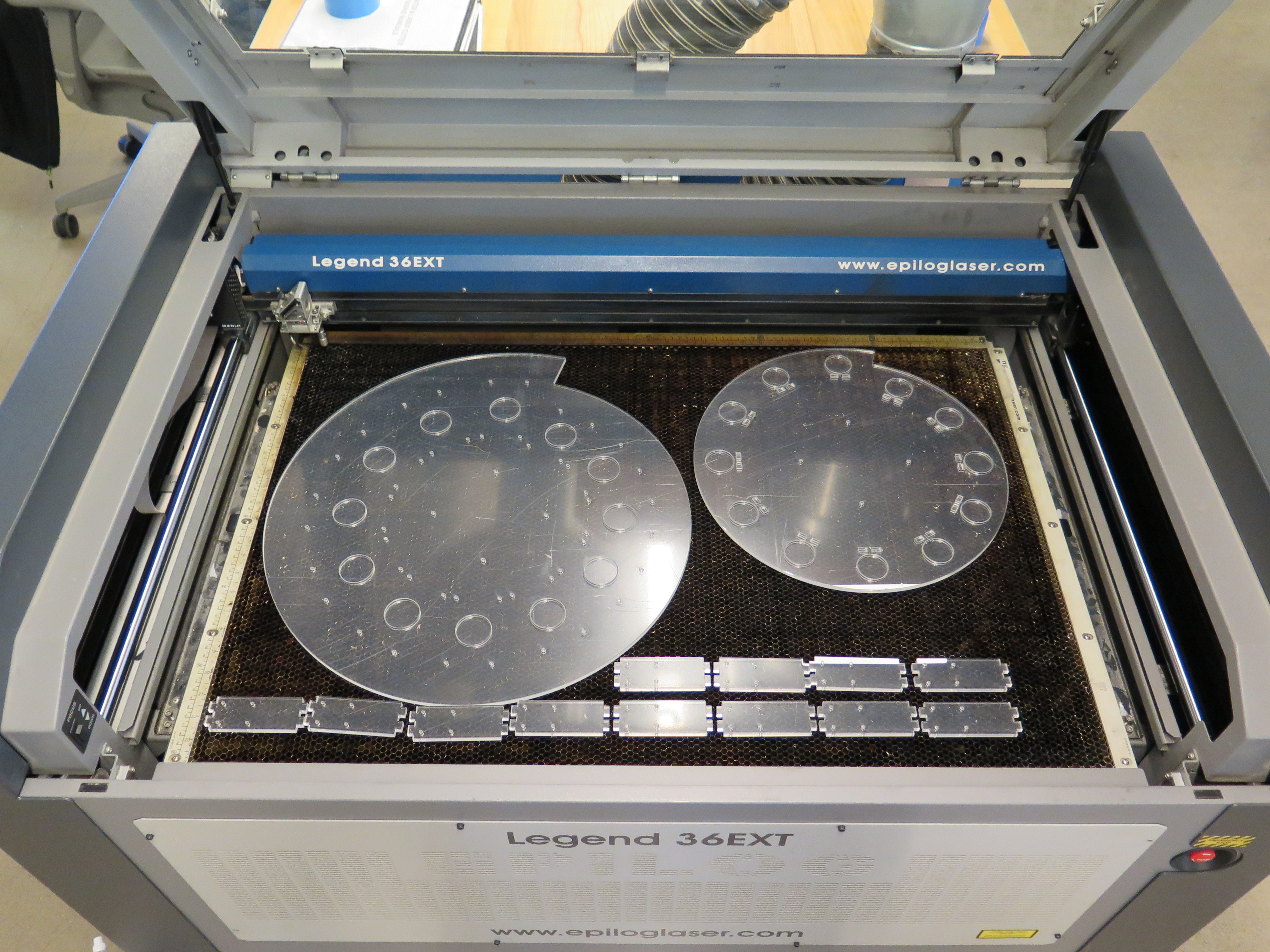
- 2 x Clear Acrylic 0.25" (0.236"), 36" x 24"
Steps:
- Download attached DXF files
- Laser cut, you may have to do two passes depending on the power of you cutter
Tie Keys to Top Layers of Acrylic
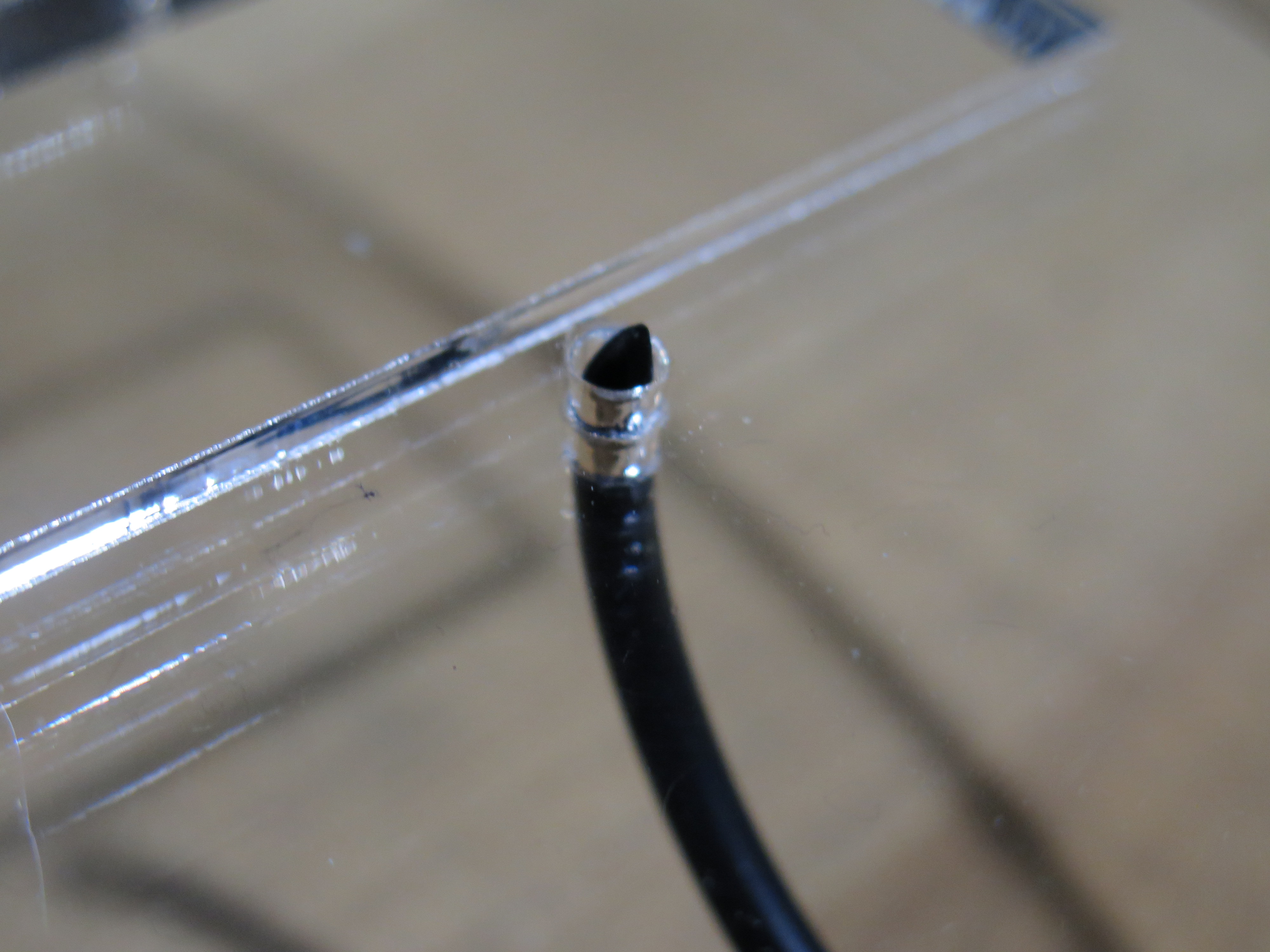
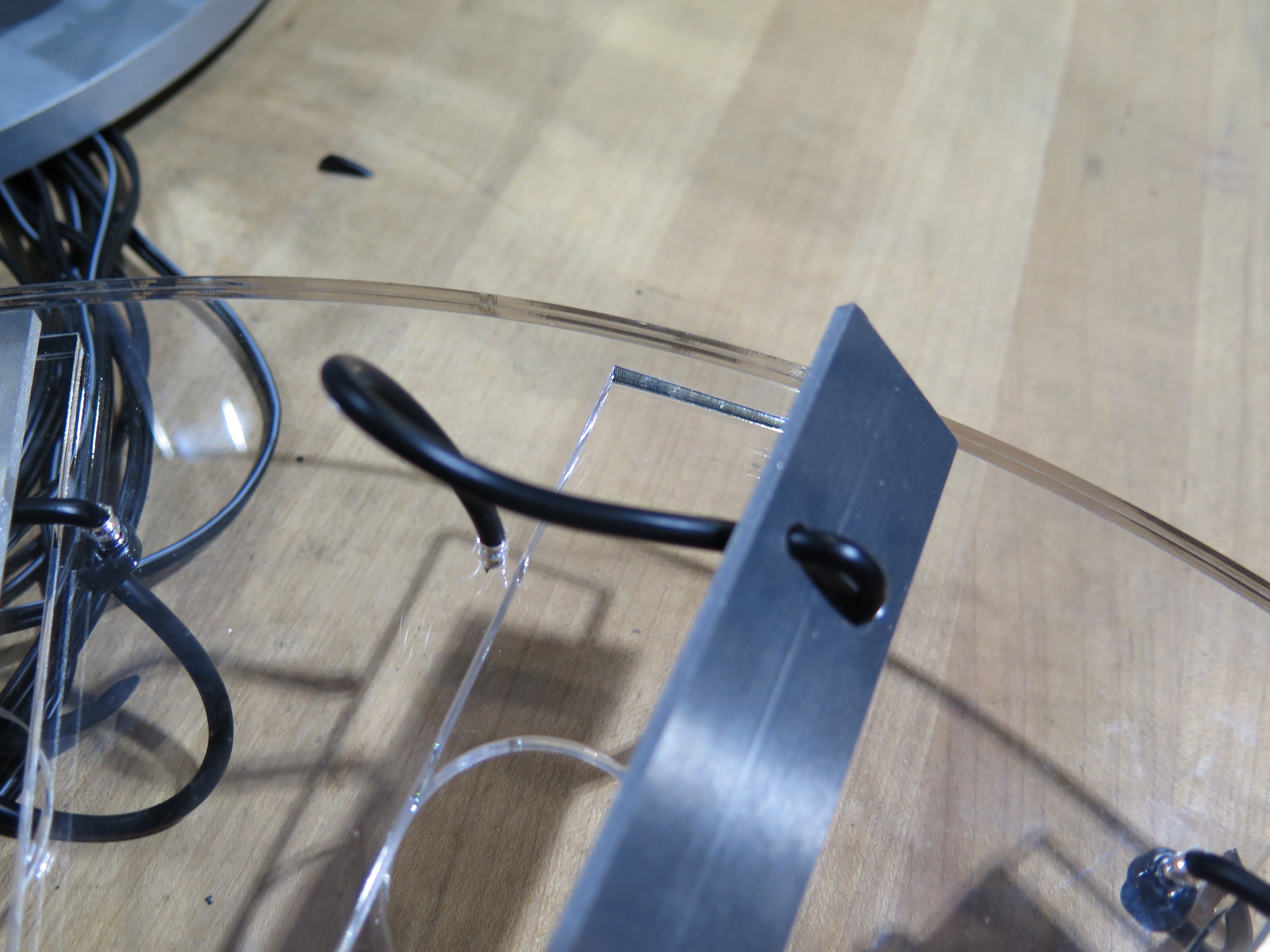
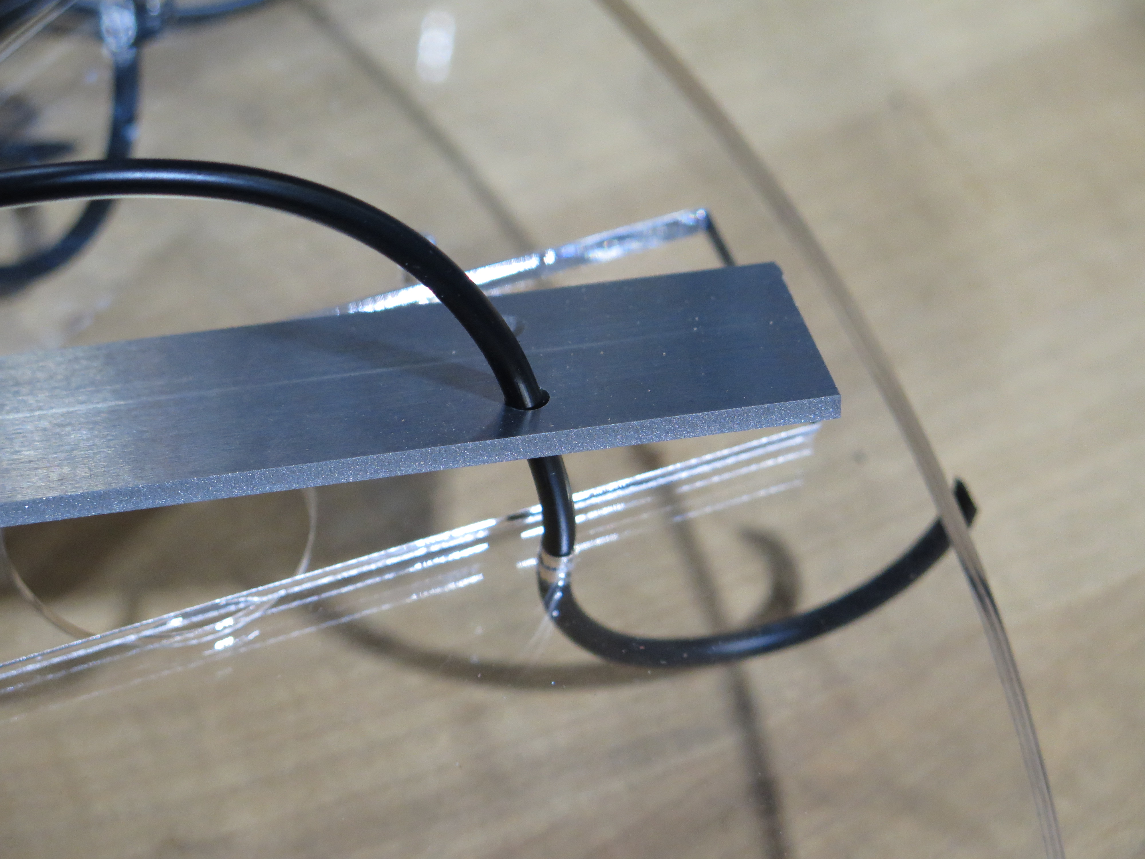
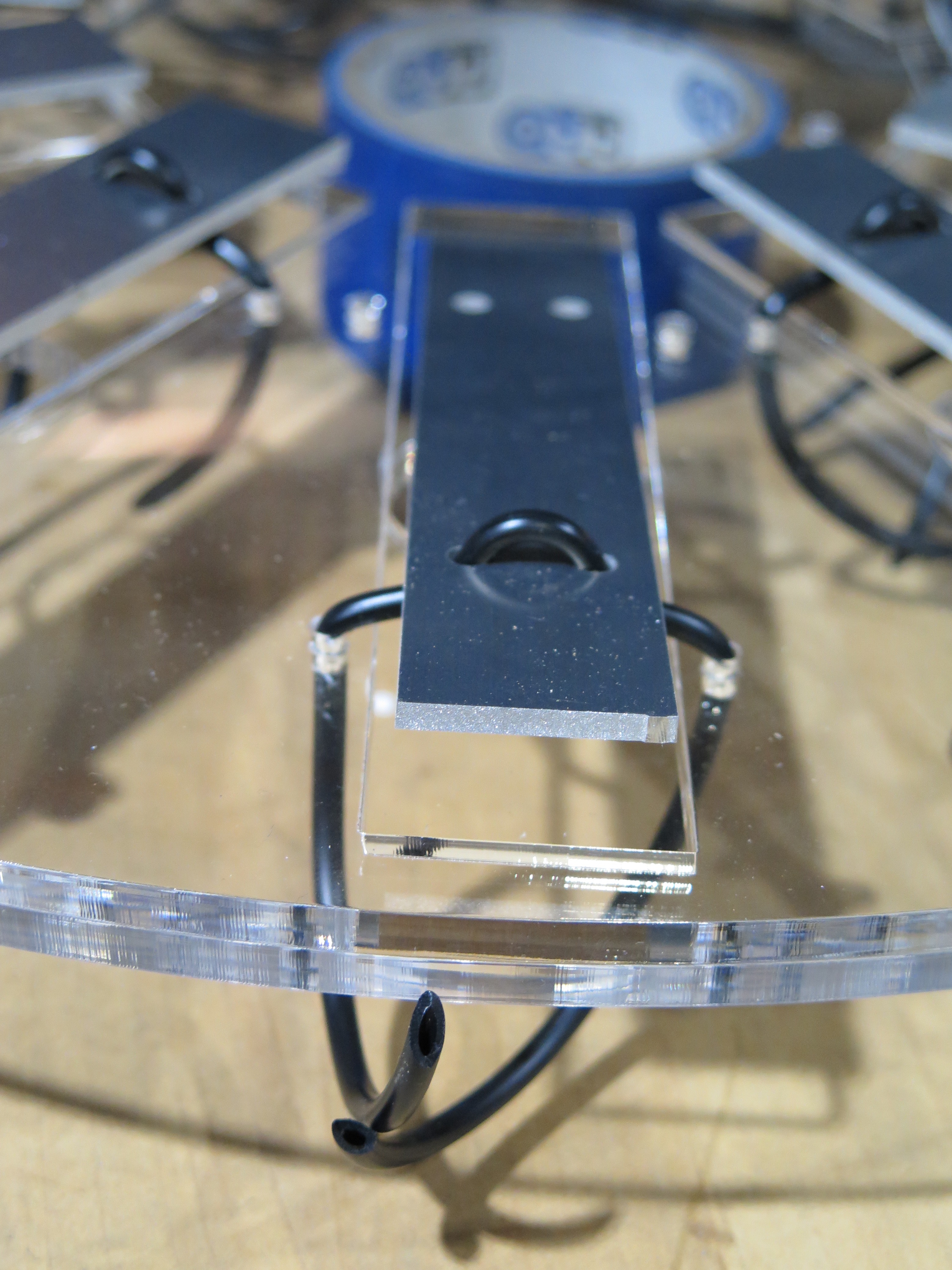
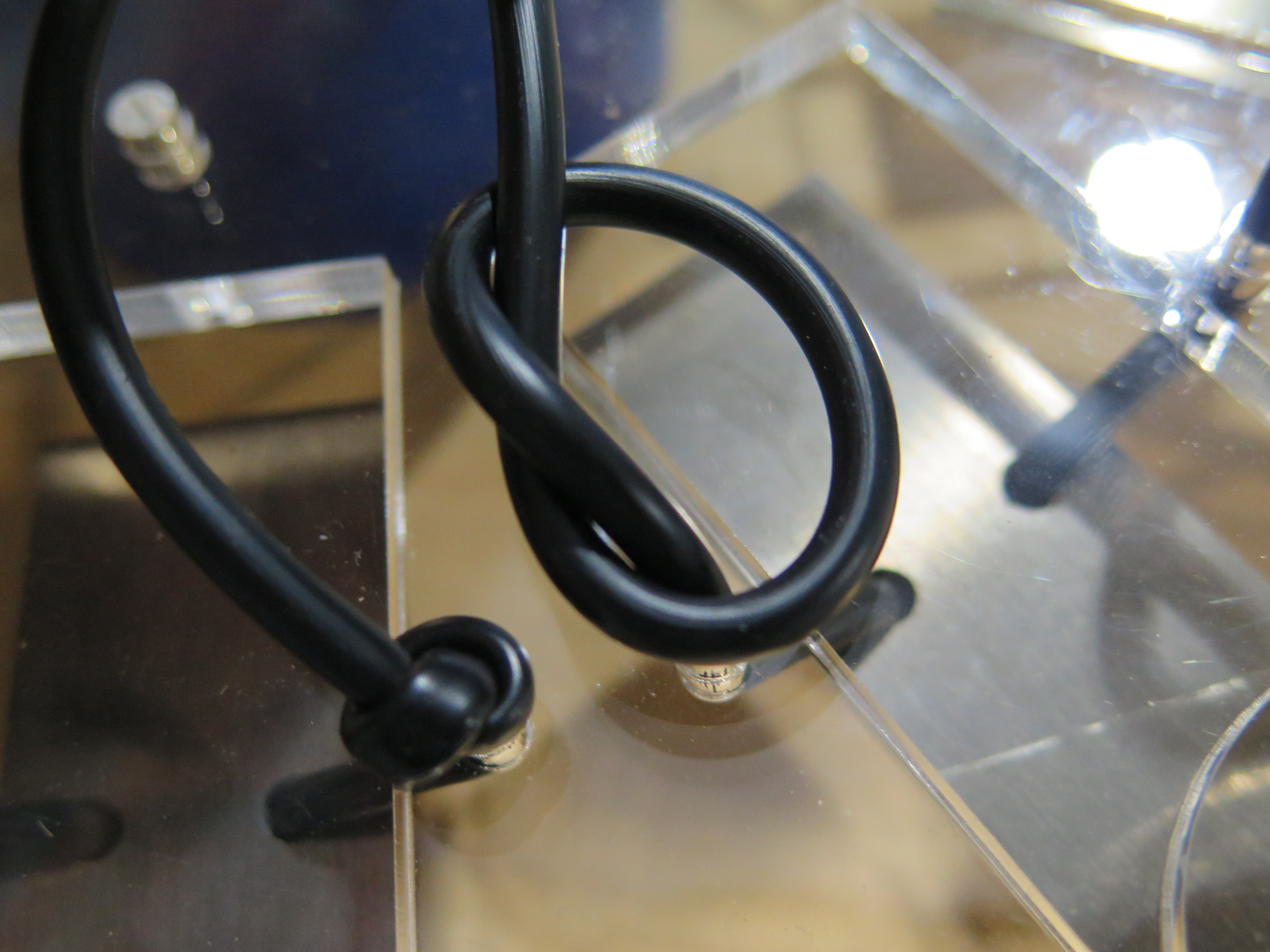
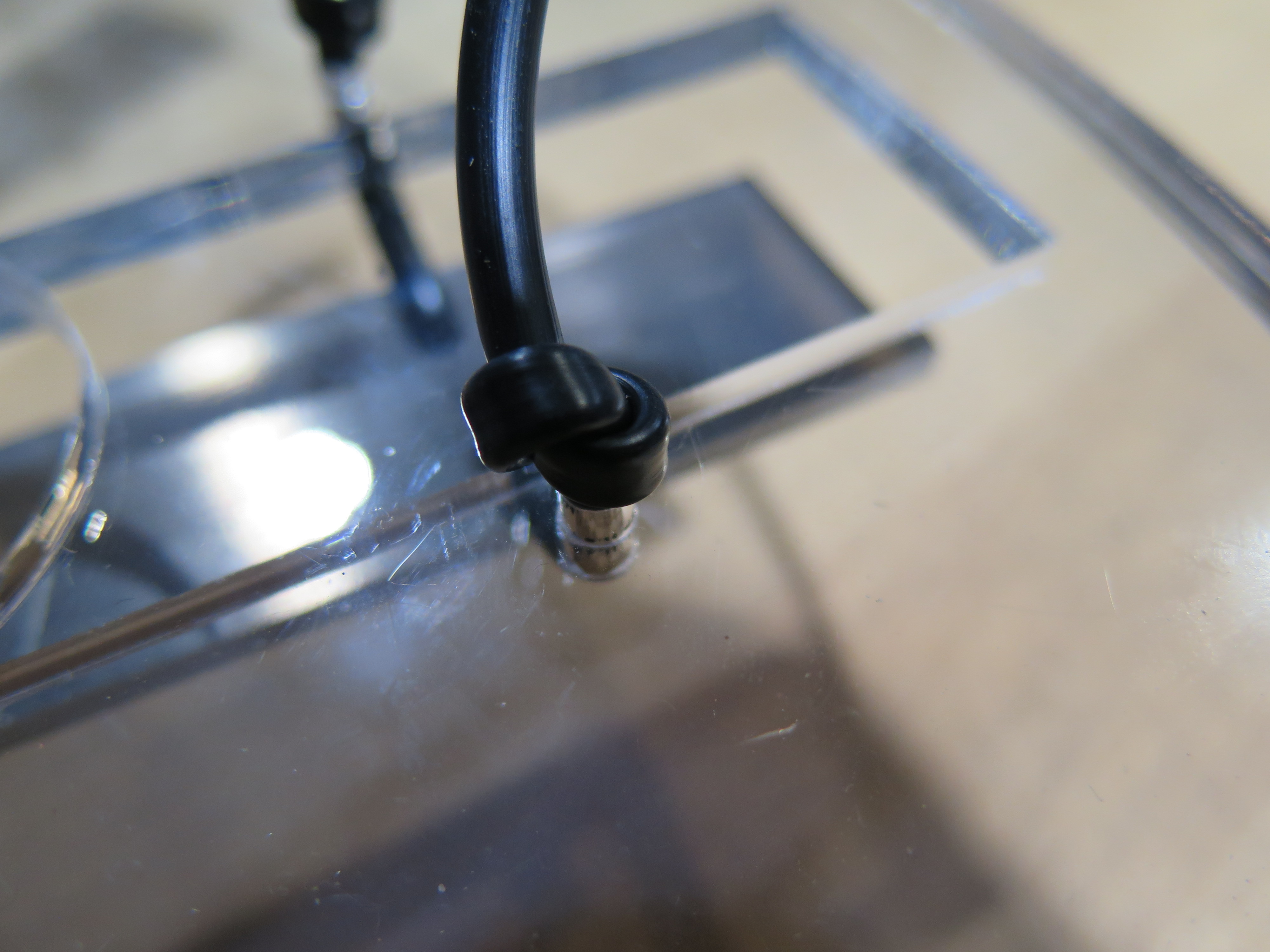
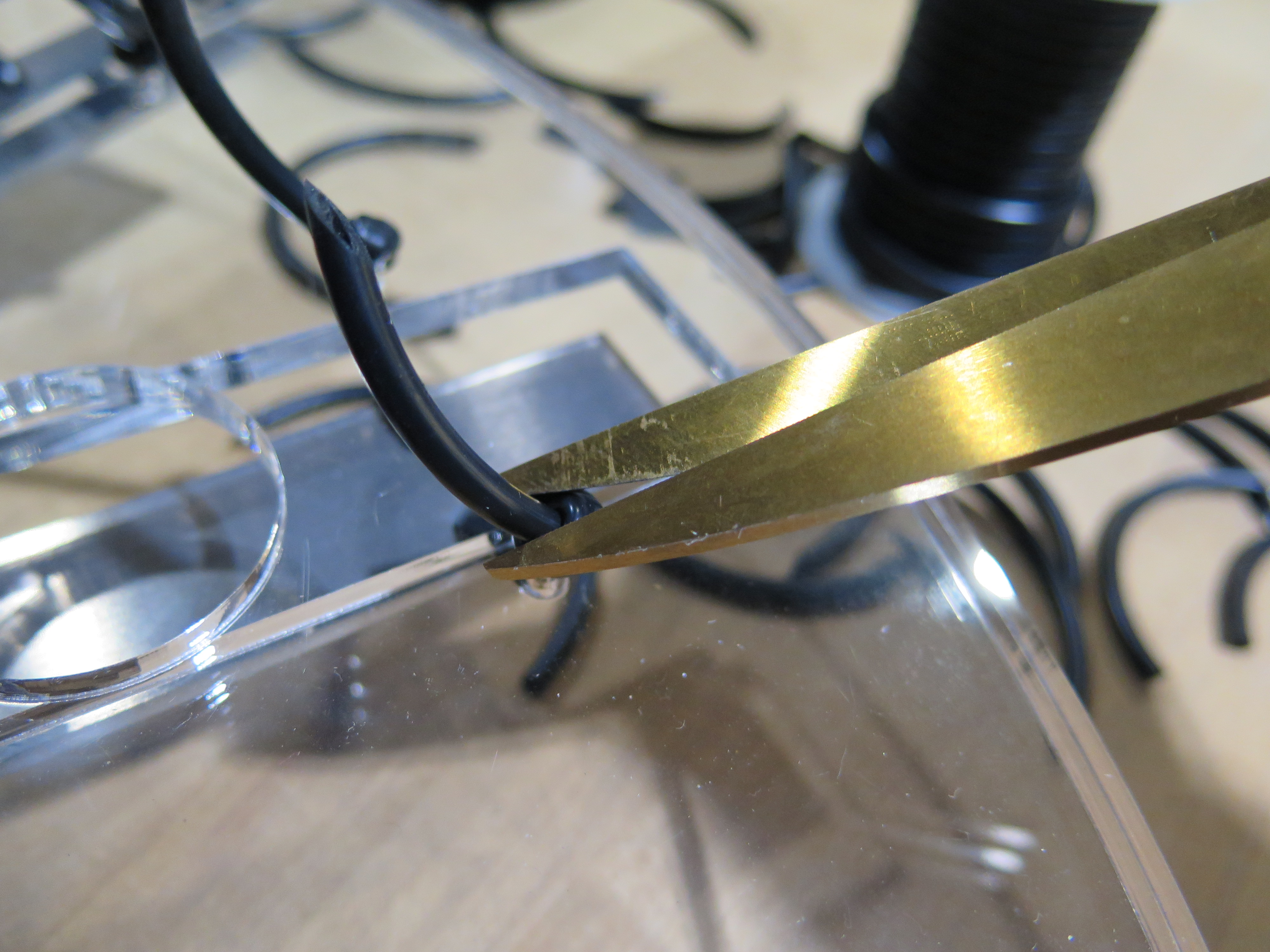
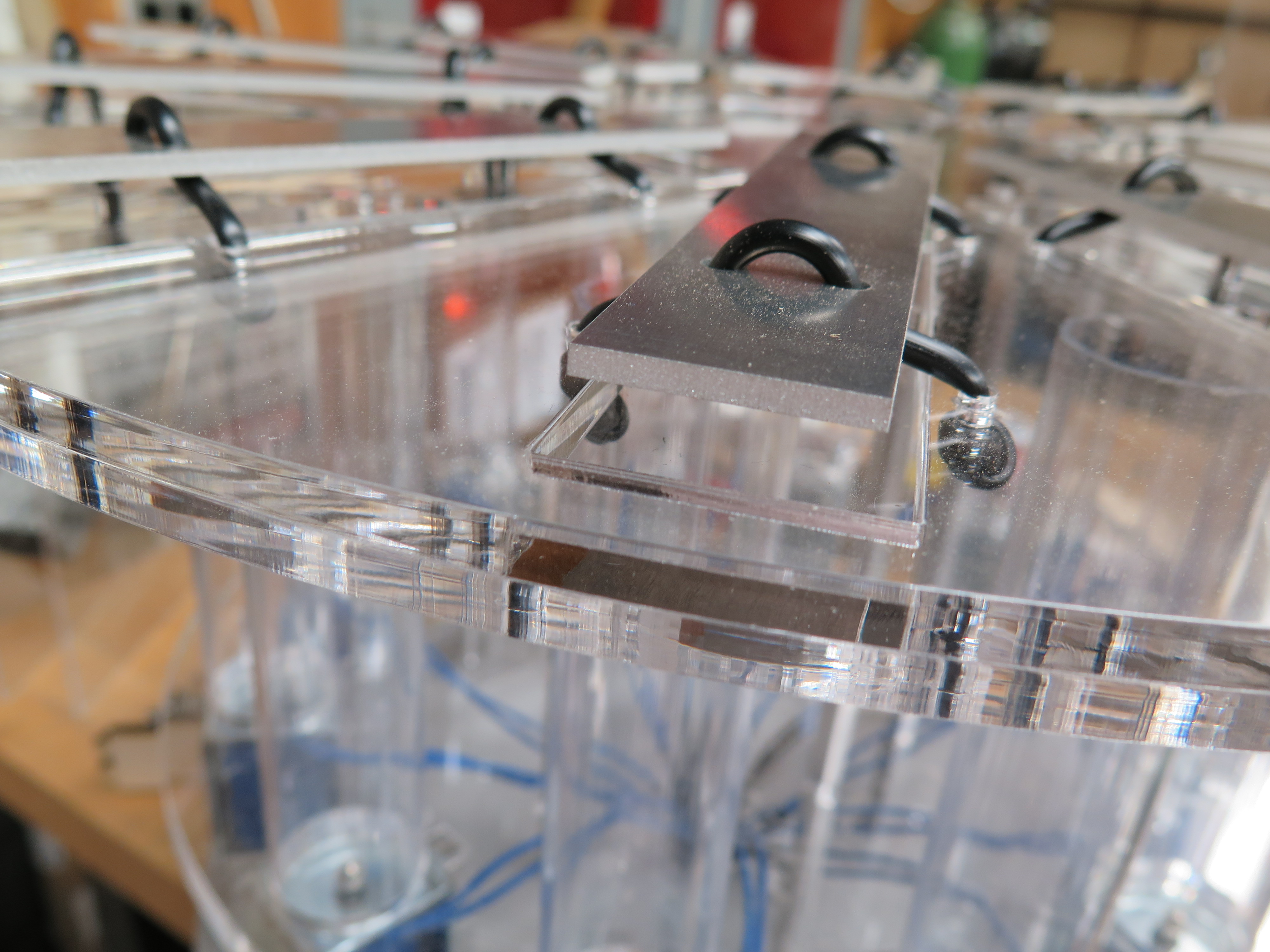
Parts:
- Two largest pieces of acrylic laser cut in the previous step
- Keys that you waterjet cut
- Rubber cord
Steps:
- Line up the two pieces of acrylic.
- Arrange the keys in order of size.
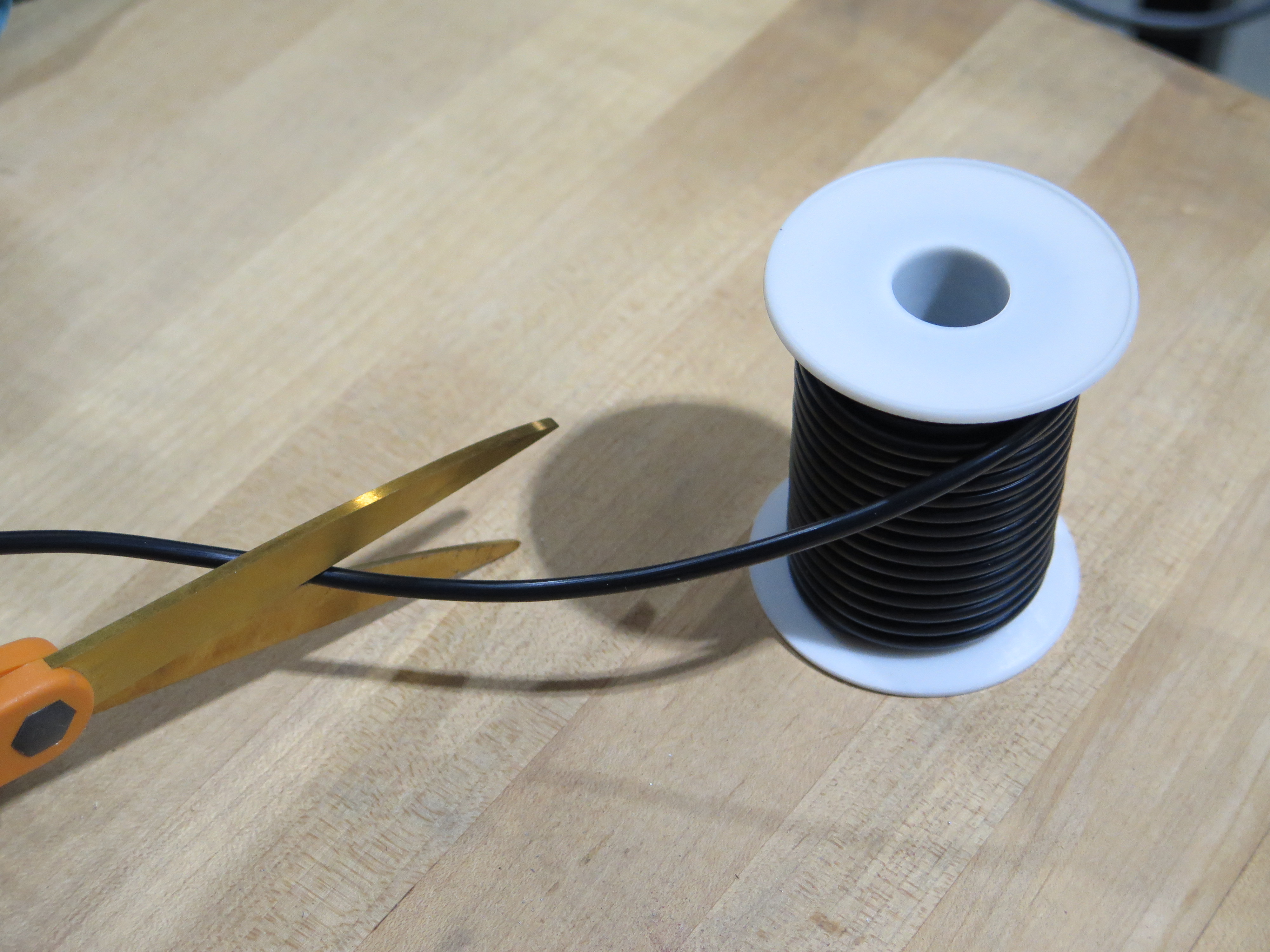
- Cut a short length of cord.
- Pick a hole in the acrylic and find the key of corresponding size.
- Thread the cord through both sheets of acrylic.
- Thread it through a hole on one side of the key and out a hole on the other size.
- Knot each end.
- Cut excess.
- Rinse and repeat with the remaining keys.
Cut Polycarbonate Tubing to Size
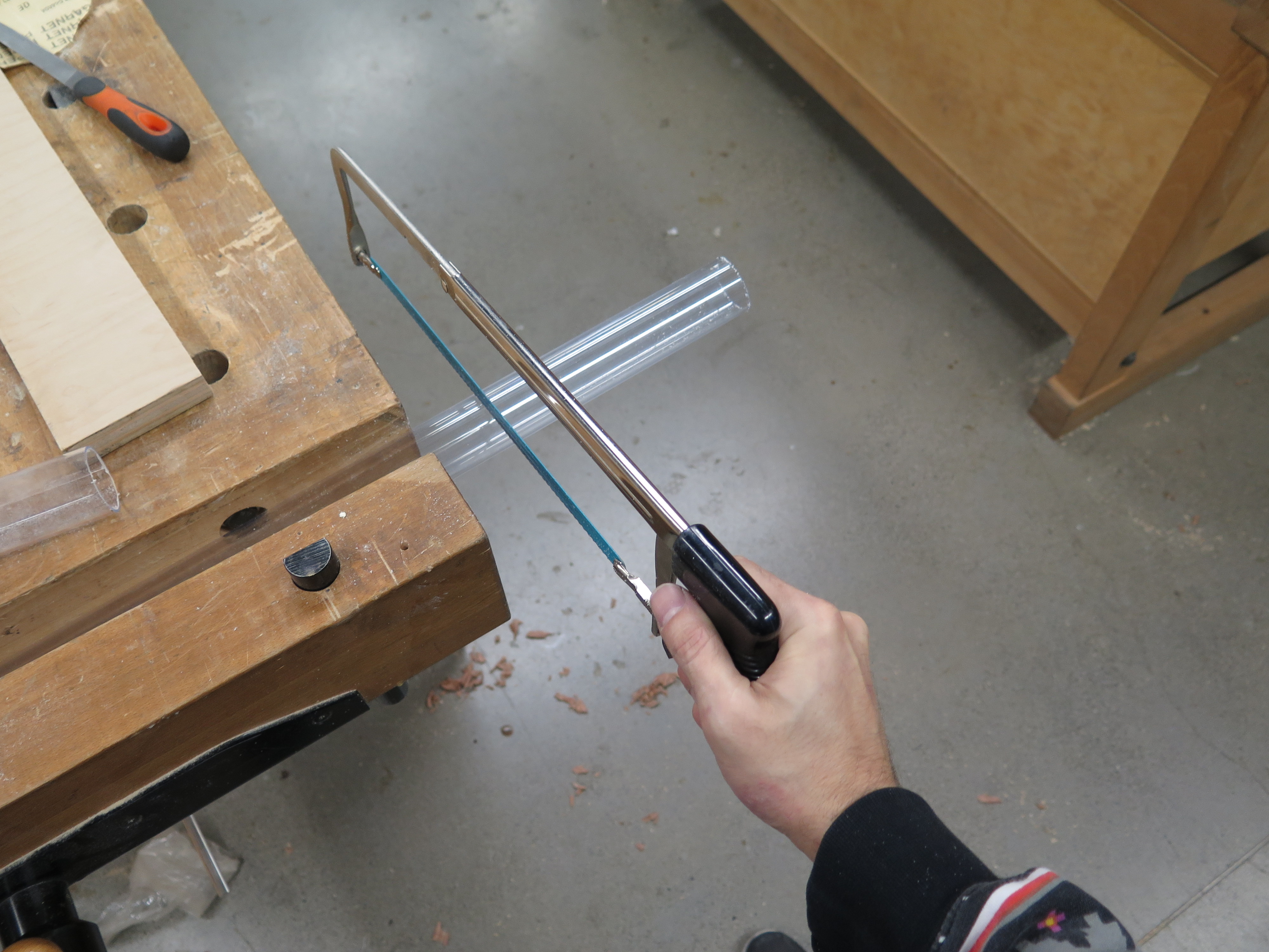
Parts:
- Polycarbonate Tubing 1 1/2" OD
Steps:
- Measure and mark 3 1/2" from end of tubing.
- Clamp tubing.
- Use a hacksaw to cut at the mark you made.
- Sand off rough edges.
Extend Solenoid Cables
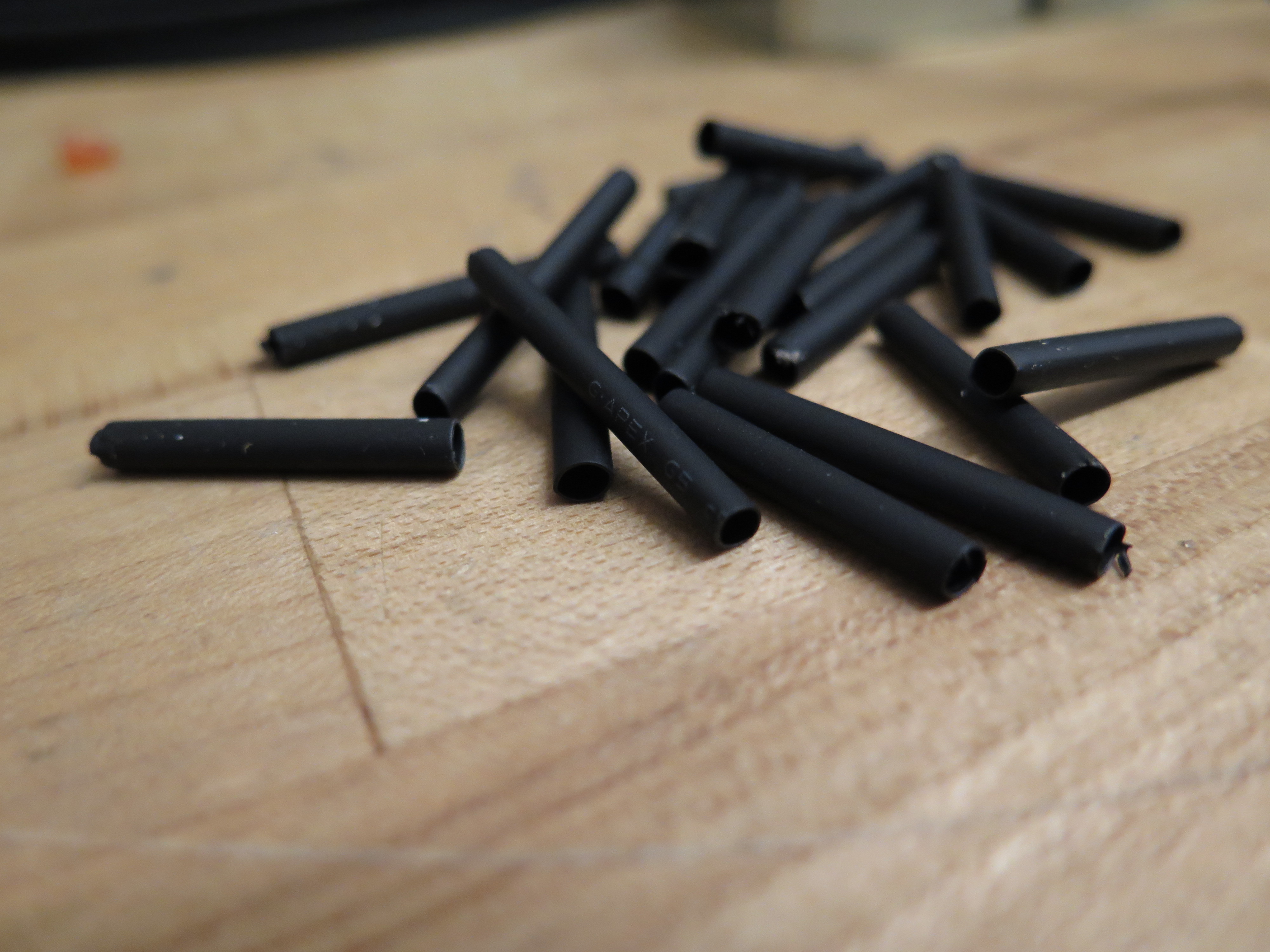
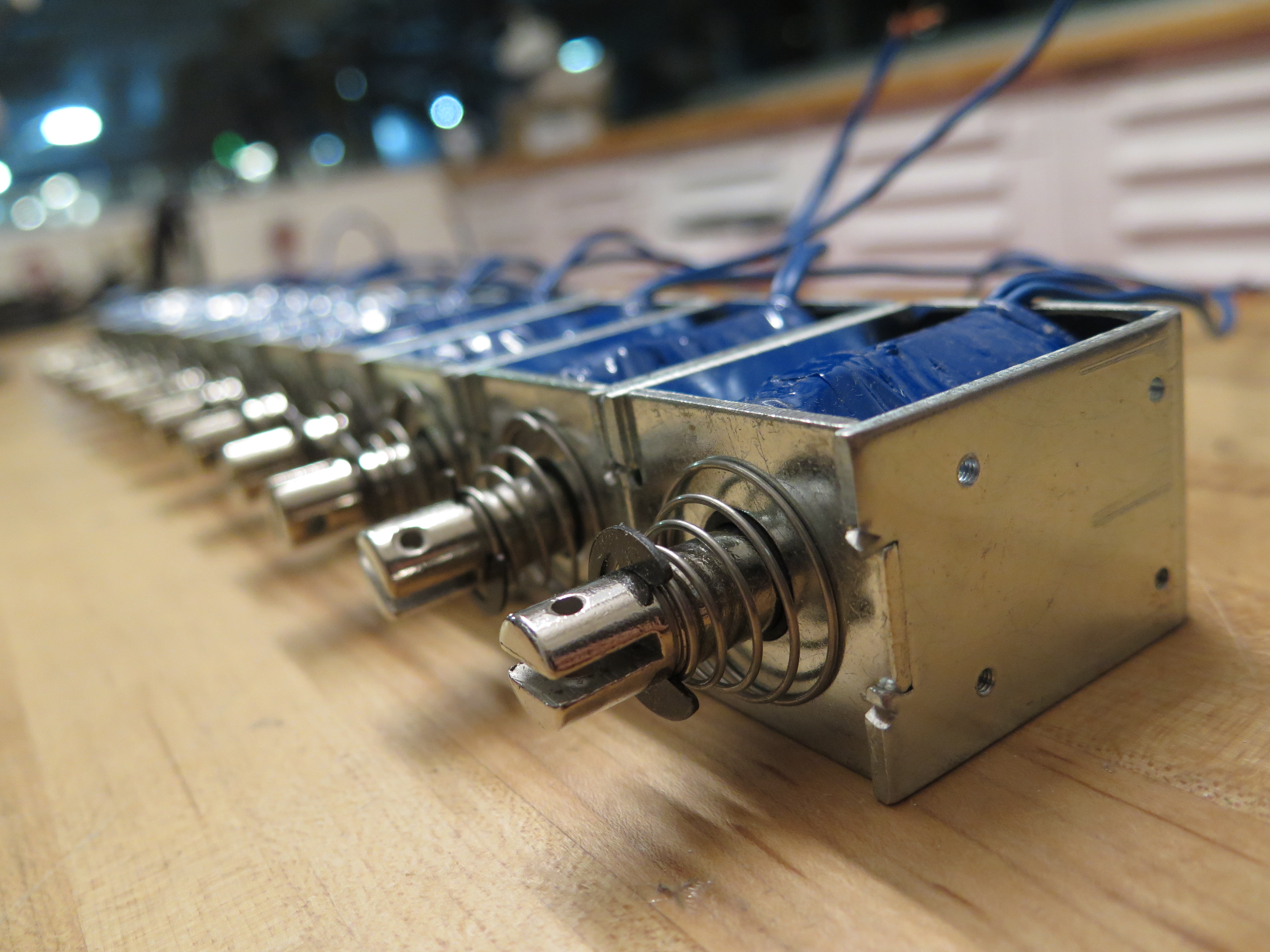
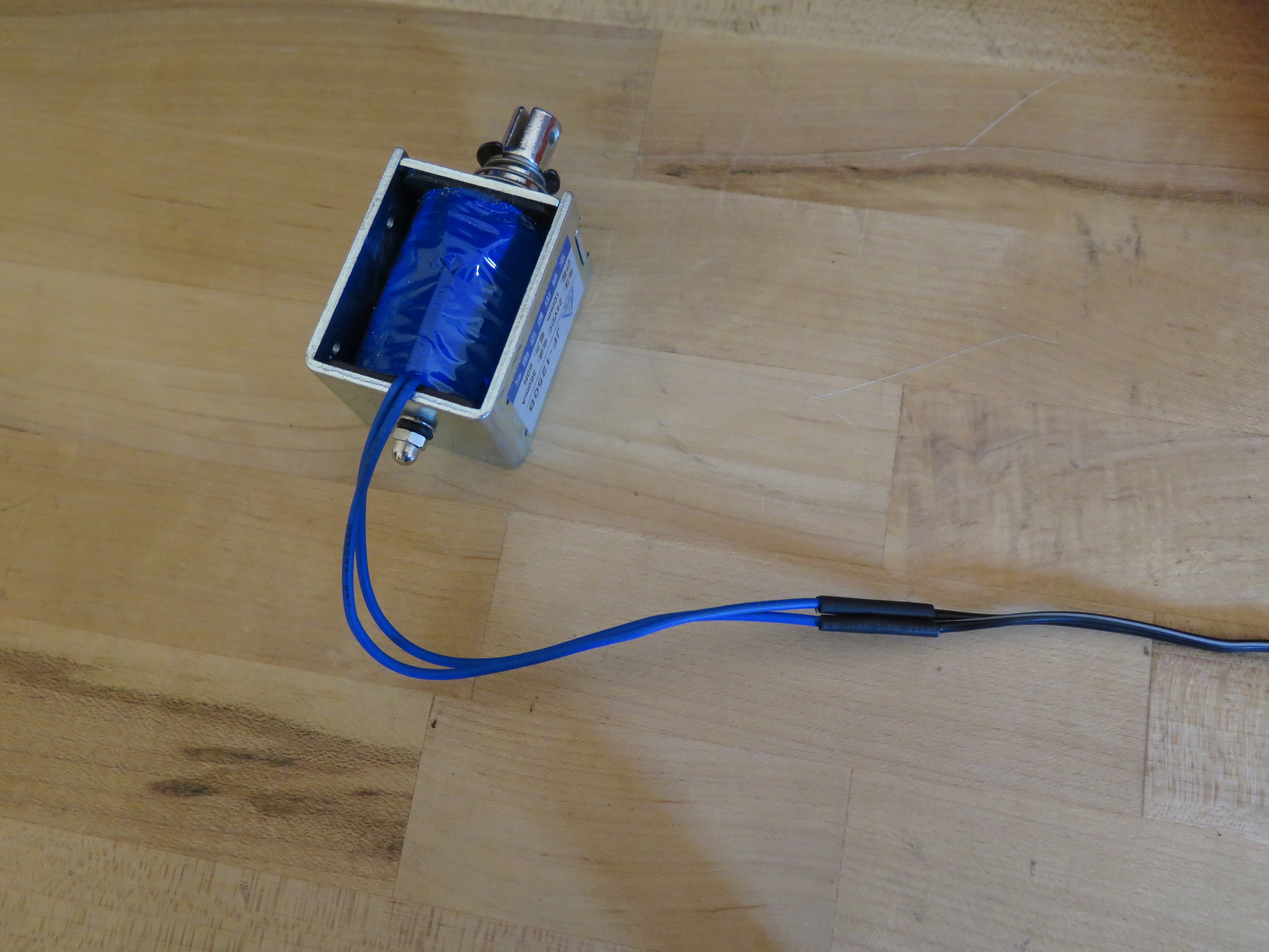
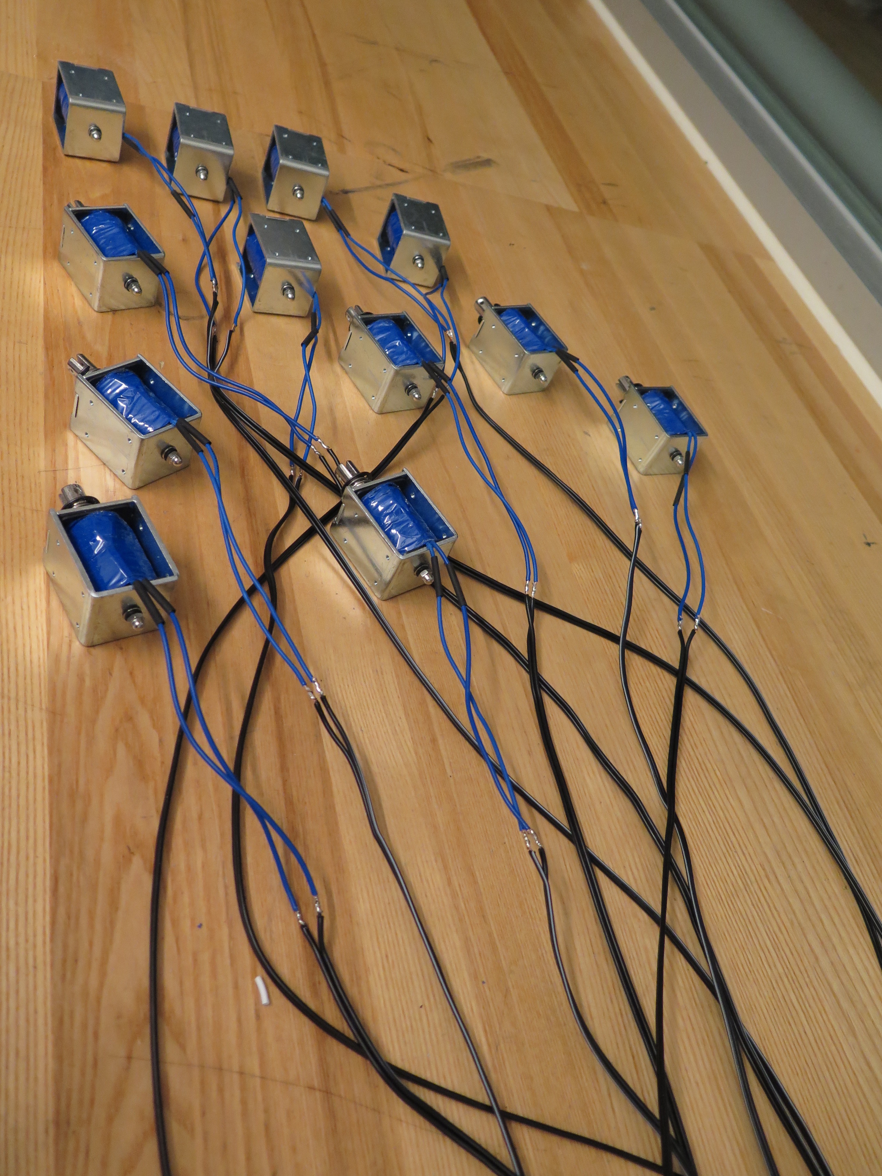
Parts:
- 12 x Solenoids
- Speaker Cable
- Heat Shrink for Speaker Cable
Steps:
- Cut 24 small pieces of heat shrink.
- Cut 24 lengths of speaker cable. The length will depend on how far away you'd like the instrument to be from the electronics.
- Put heat shrink over solenoid cables.
- Solder speaker cable to solenoid cables.
- Move heat shrink over exposed wires and then use heat gun to shrink it.
Assemble Solenoid Components
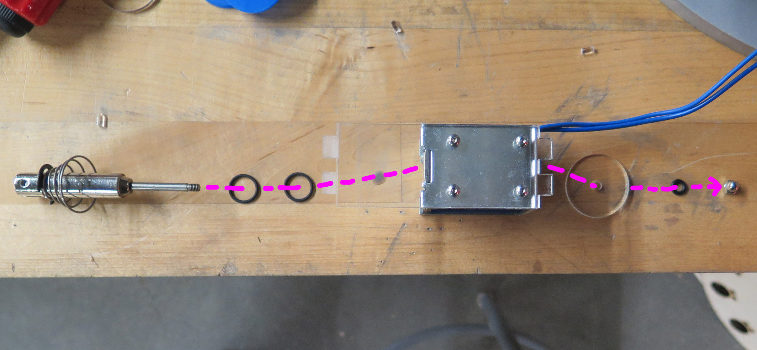
Parts:
- 12 x Solenoids
- 24 x 12mm Inner Diameter O-Ring
- 12 x Laser Cut Solenoid Holders
- 12 x Laser Cut Plungers
- 12 x M3 x 6 Screws
- 12 x M4 Nyloc Nuts
Steps:
- Screw solenoid to solenoid holder with M3 screws
- Remove the plunger from the solenoid and then reassemble it with the extra components as show in the picture. Replace the nut that comes with the solenoid with a nyloc to prevent it coming lose.
Screw Standoffs to Base
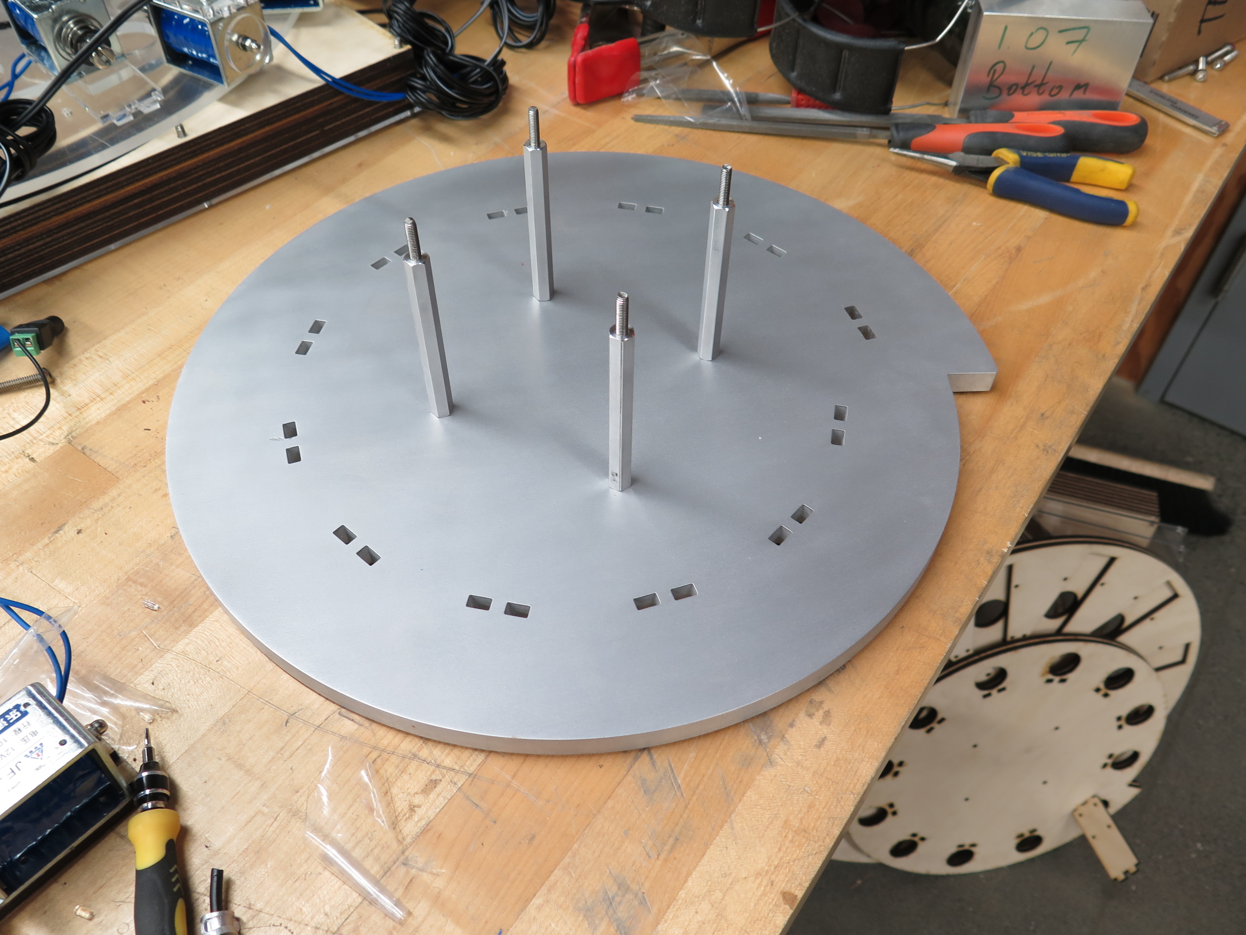
Parts:
- Waterjet Cut Base
- 8 x Aluminum Female Threaded Hex Standoff, 3/8" Hex, 3-1/2" Length, 10-32 Thread Size
- 8 x 7/8" 10-32 screws
- 4 x 1" 10-32 studs
Steps:
- Screw standoffs to base.
- Screw studs into standoffs.
Insert Solenoids Into Base
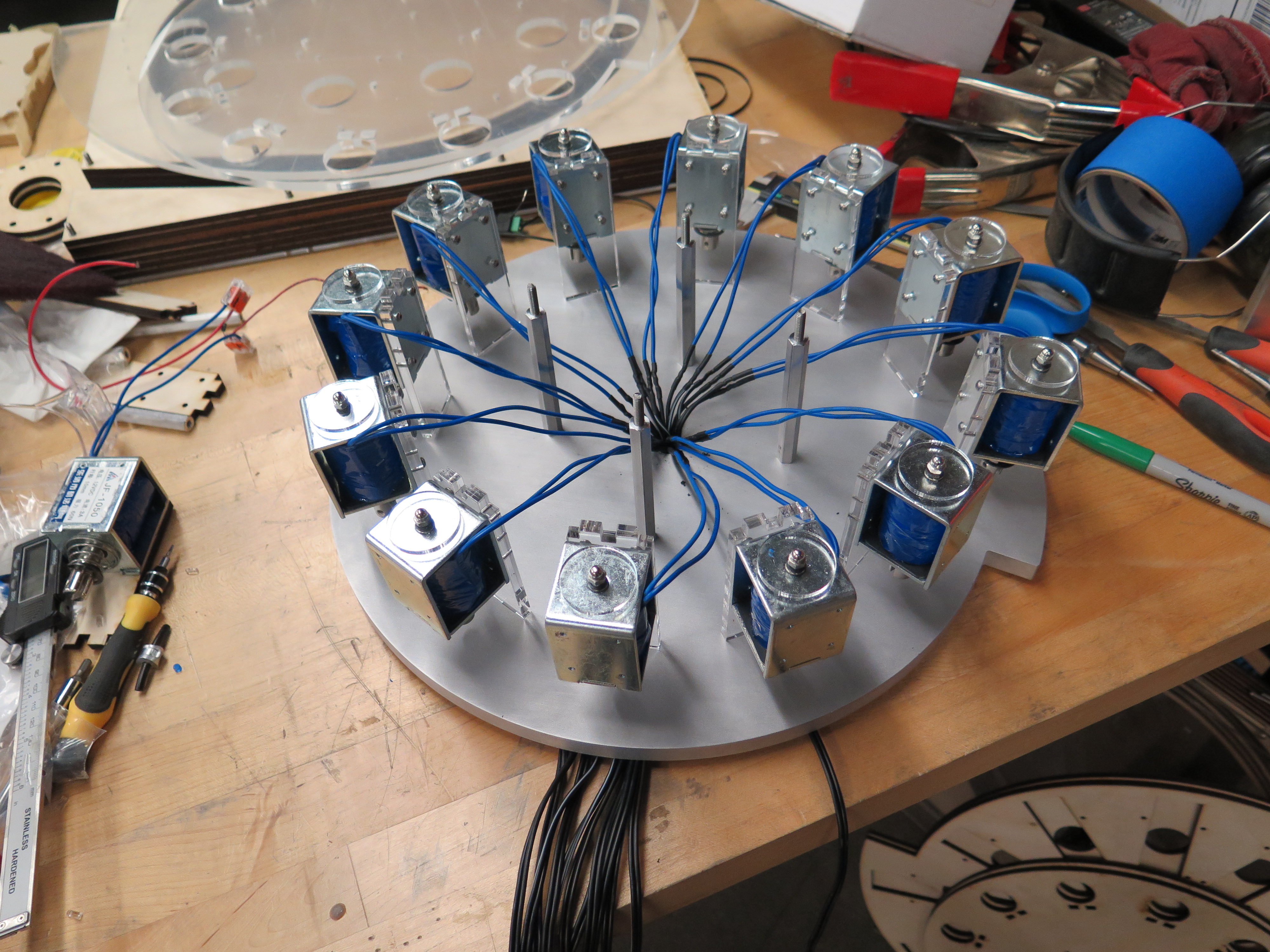
Parts:
- Solenoids
- Base
- Blue Tape
Steps:
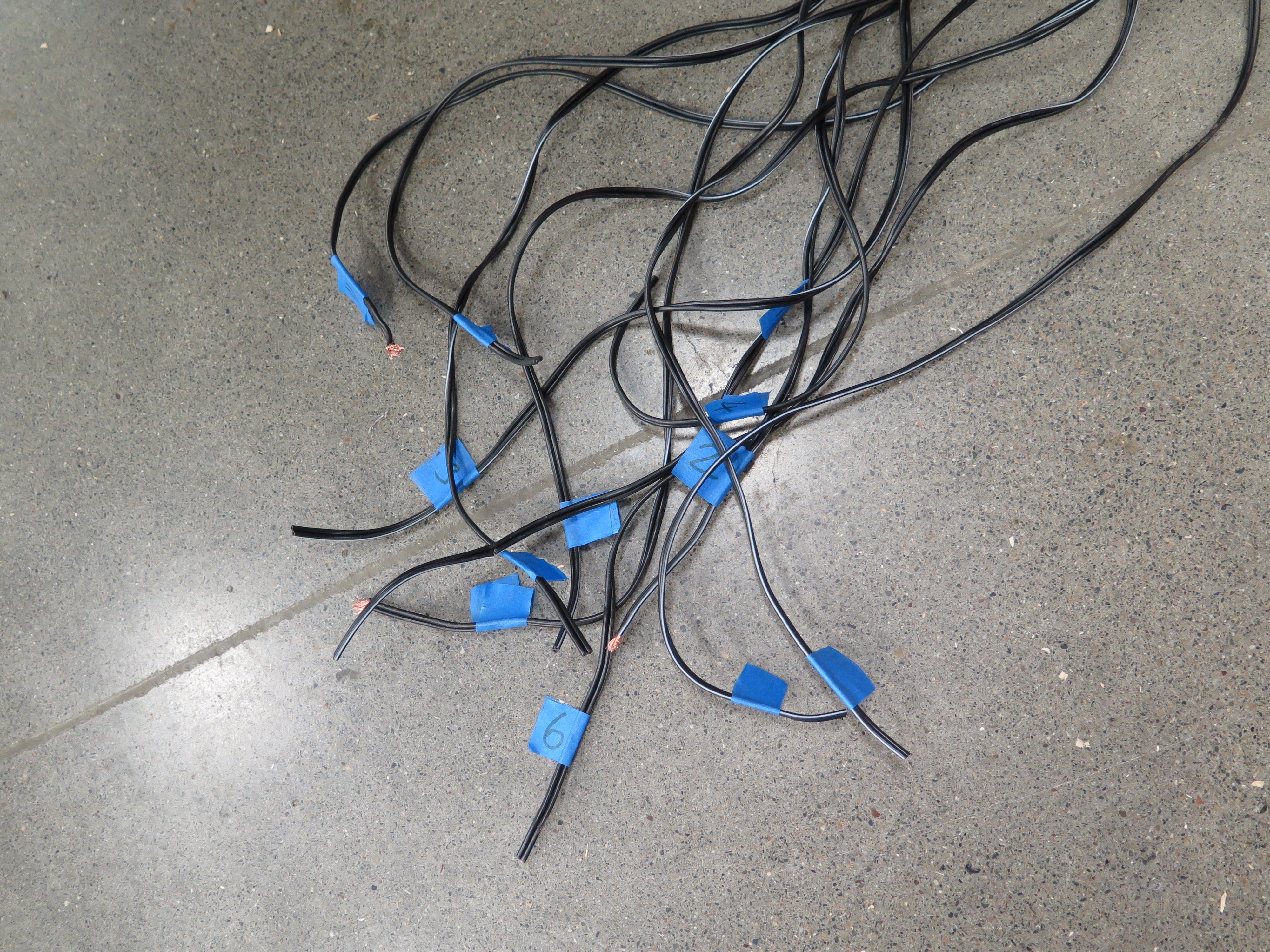
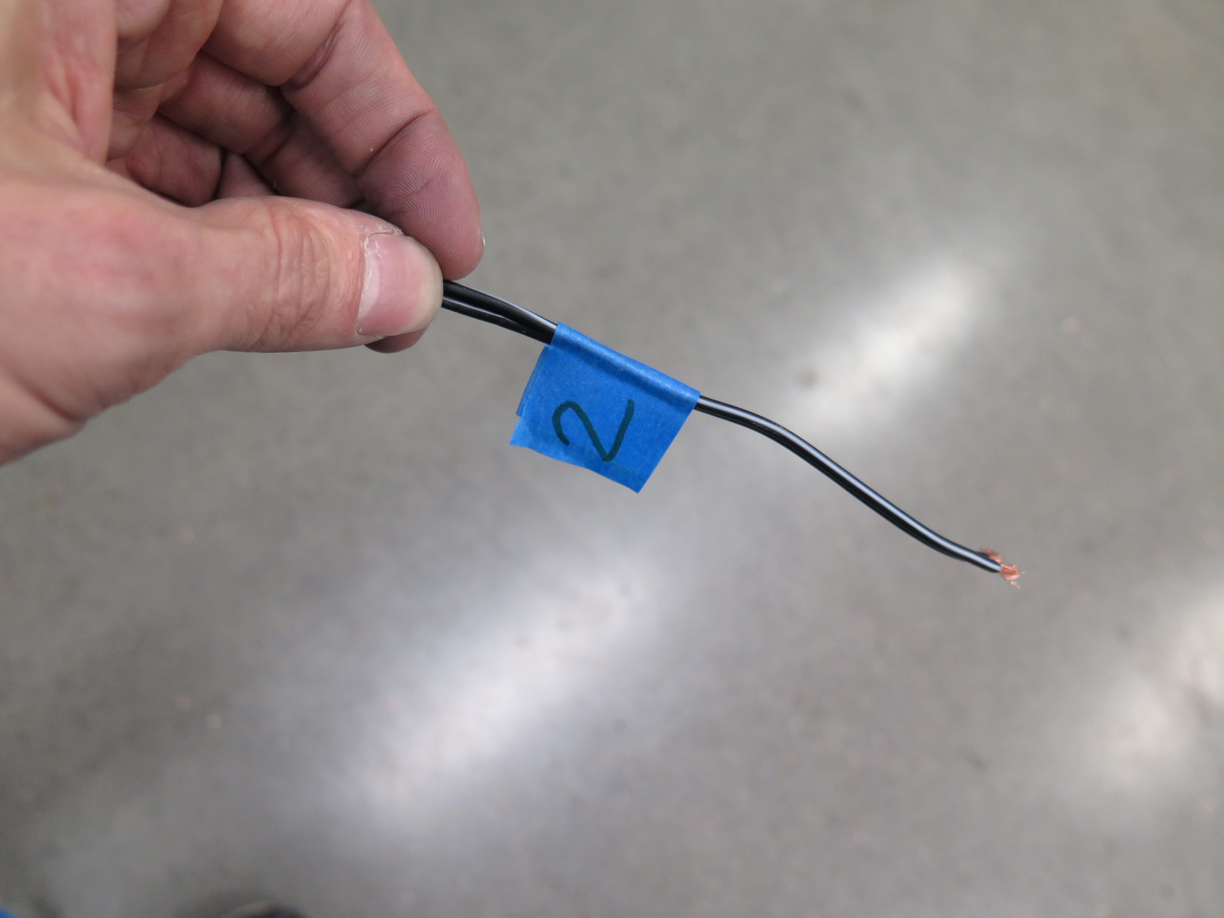
- Label each of the cables from 1 to 12 with the tape.
- Insert solenoid 1 into the part of the base with the largest radius (the longest key will have the lowest note).
- Pull the cable through the hole in the centre of the base.
- Repeat with the rest of the solenoids, going around the base in the direction which the radius get smaller incrementally each time (counterclockwise if your base if oriented the same as the one in the photo).
Add Middle Layer
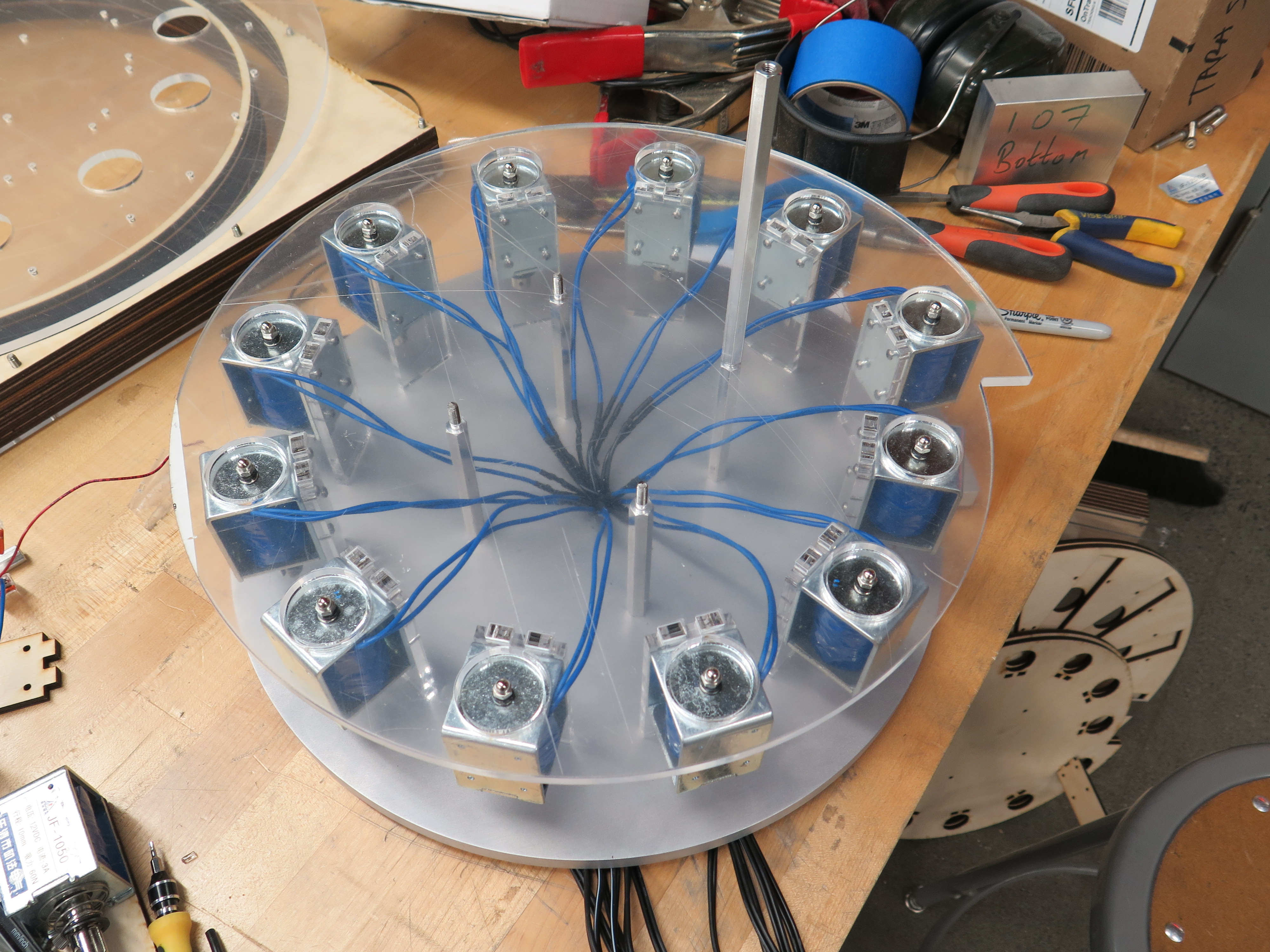
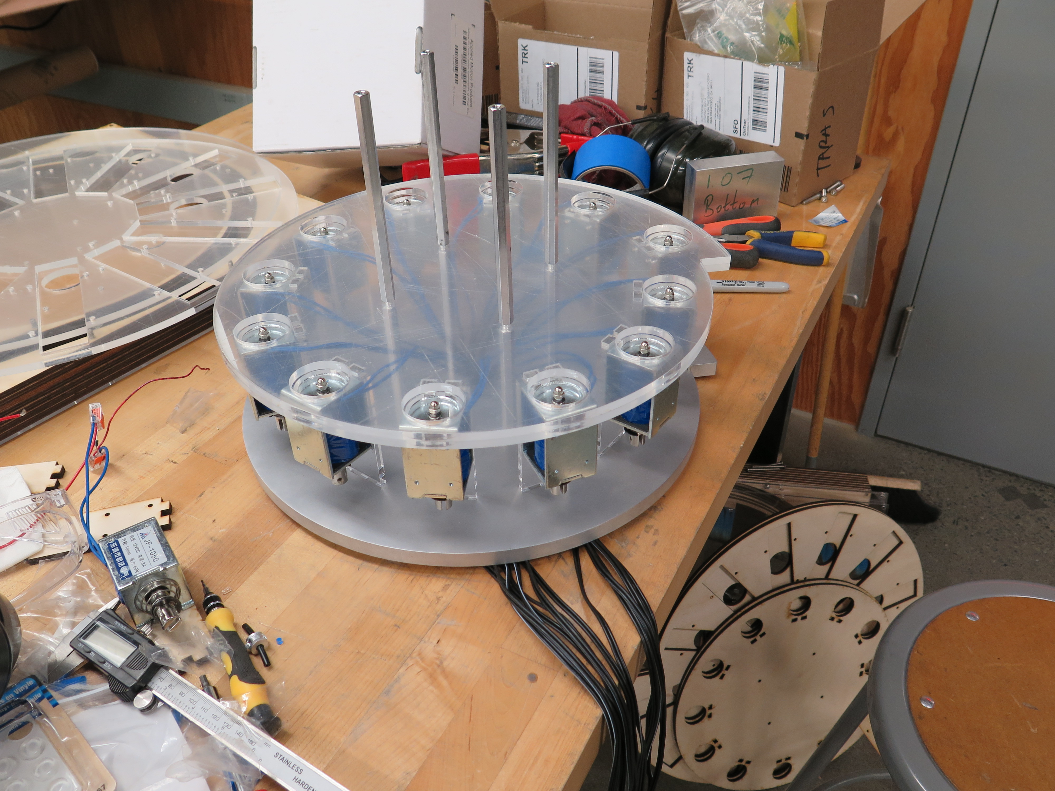
Parts:
- Assembly from Previous Step
- Laser Cut Acrylic Middle Layer (Two Remaining Unused Laser Cut Parts)
- 12 x Sections of Polycarbonate Tubing
- 4 x Aluminum Female Threaded Hex Standoff, 3/8" Hex, 3-1/2" Length, 10-32 Thread Size
- 12 x Pebbles
Steps:
- The middle layer is made up of two acrylic parts. The bottom one has rectangular holes that align with the top of the solenoid holders. Put this on top of assembly from the previous step and wiggle everything around it all aligns correctly (studs in the center and solenoid holders around the outside).
- Now put the top layer on the assembly, the studs should align with the holes in the center.
- Screw the standoffs into the studs.
- Push each of the sections of polycarbonate tubing into one of the holes above the solenoids.
- Drop a pebble into each of the tubes.
Add Top Layer
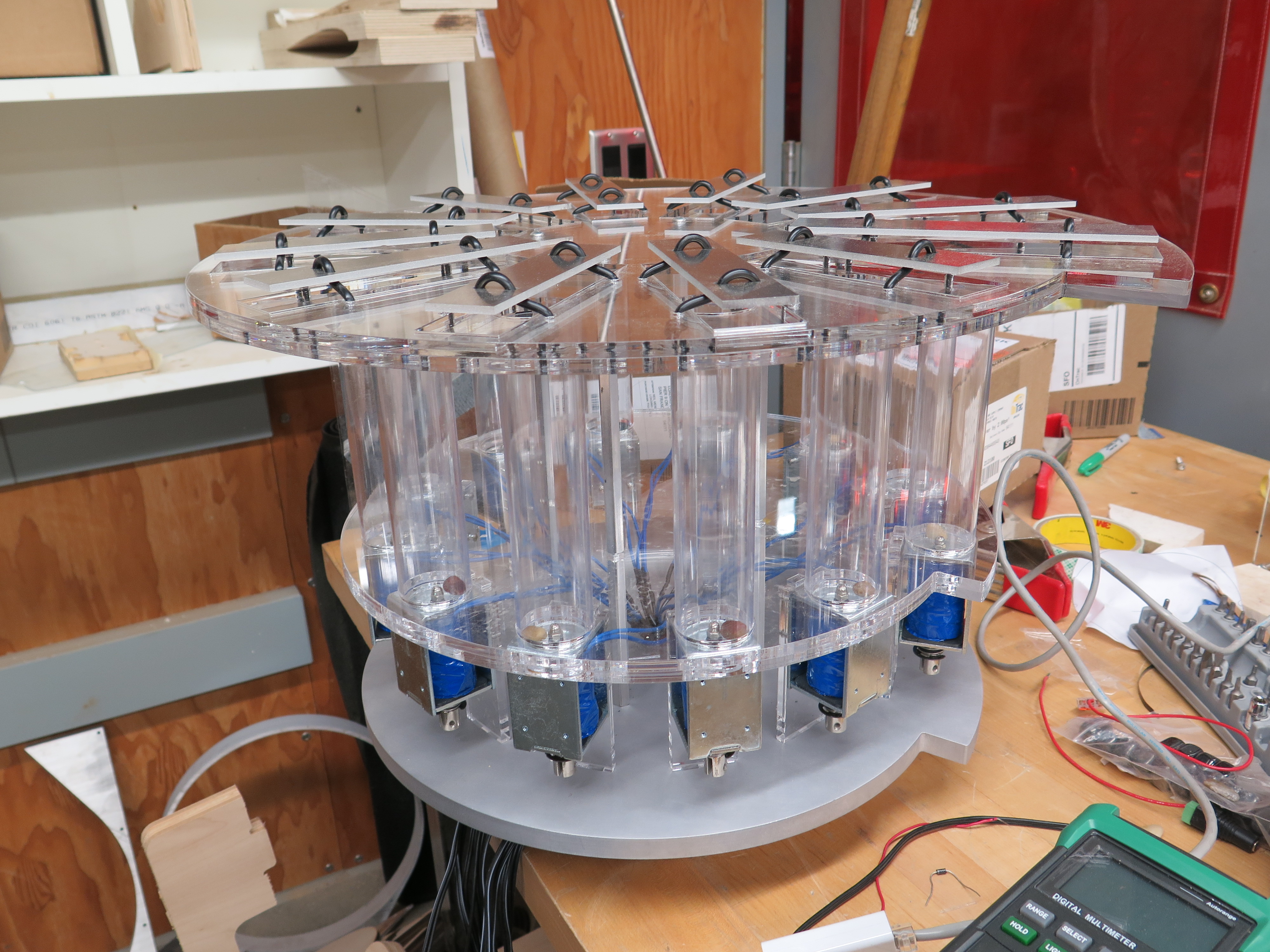
Parts:
- Assembly from Previous Step
- Top Layer with Keys
- 4 x 7/8" 10-32 Screws
Steps:
- Rest the top layer on the tubes.
- Carefully go around and check that each of the tubes is seated correctly in a hole below the keys.
- Screw the top layer down into the standoffs.
Electronics
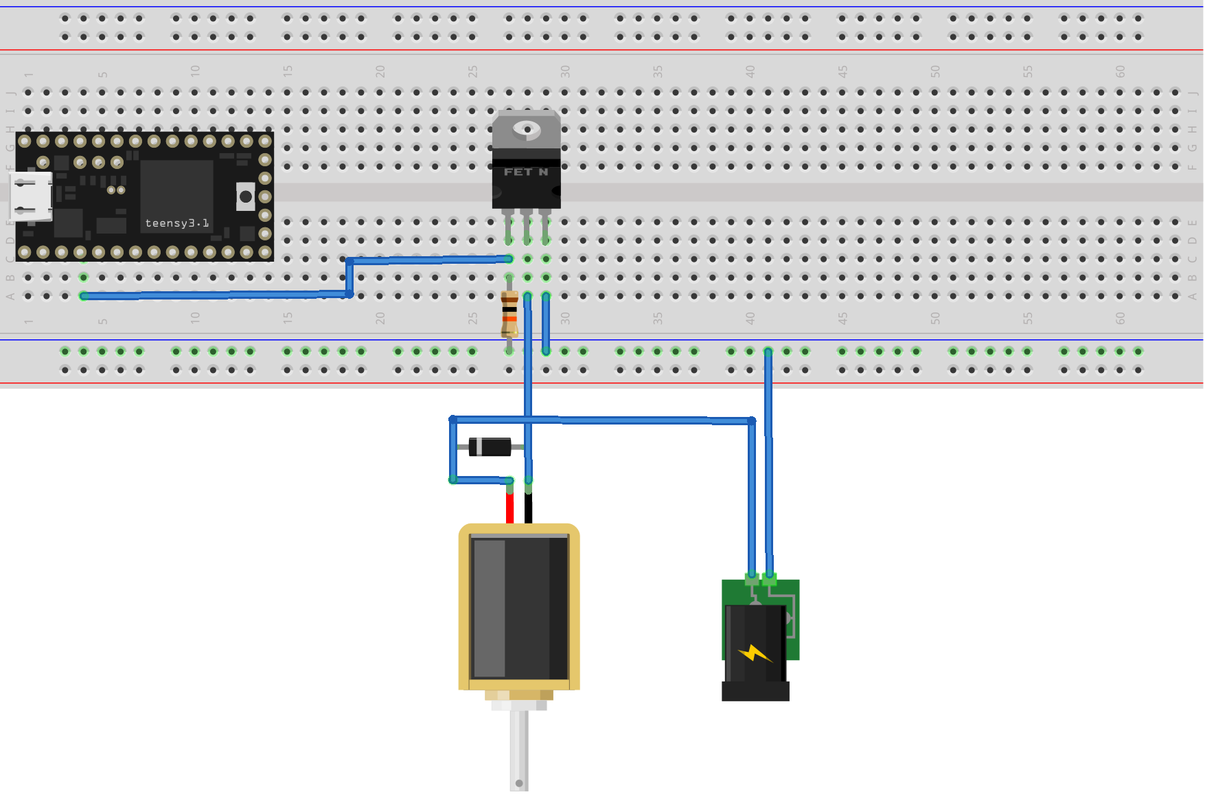
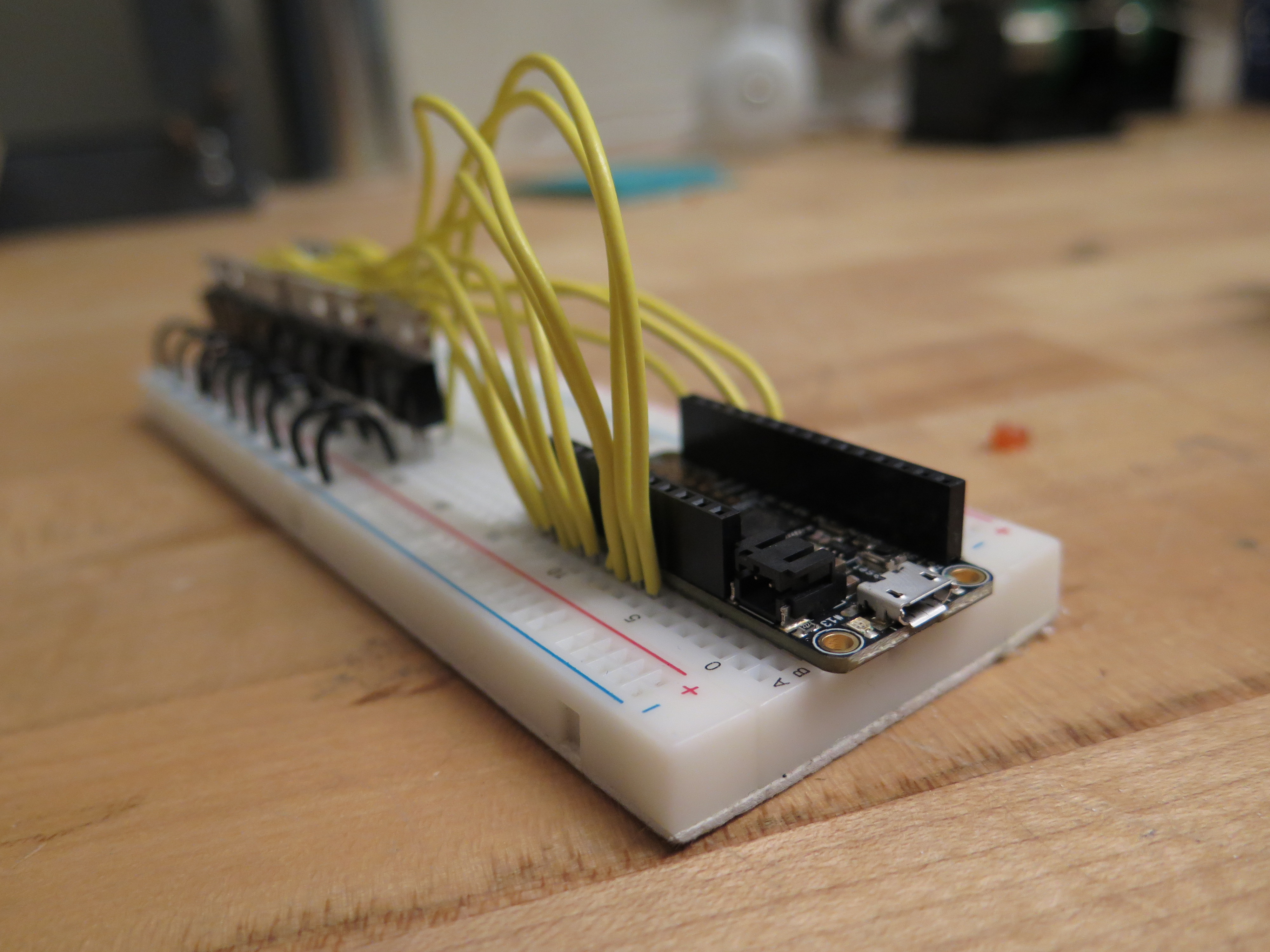
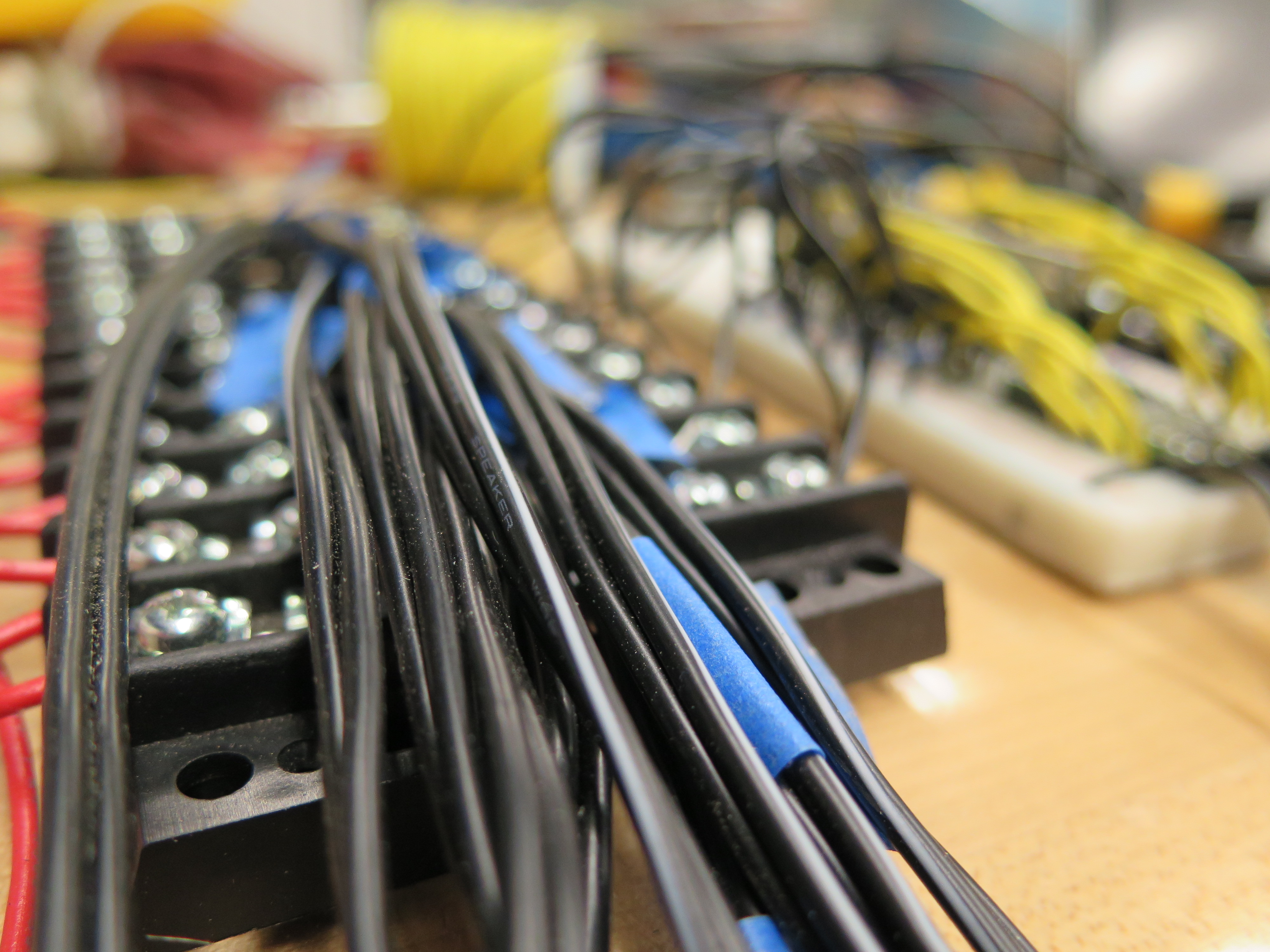
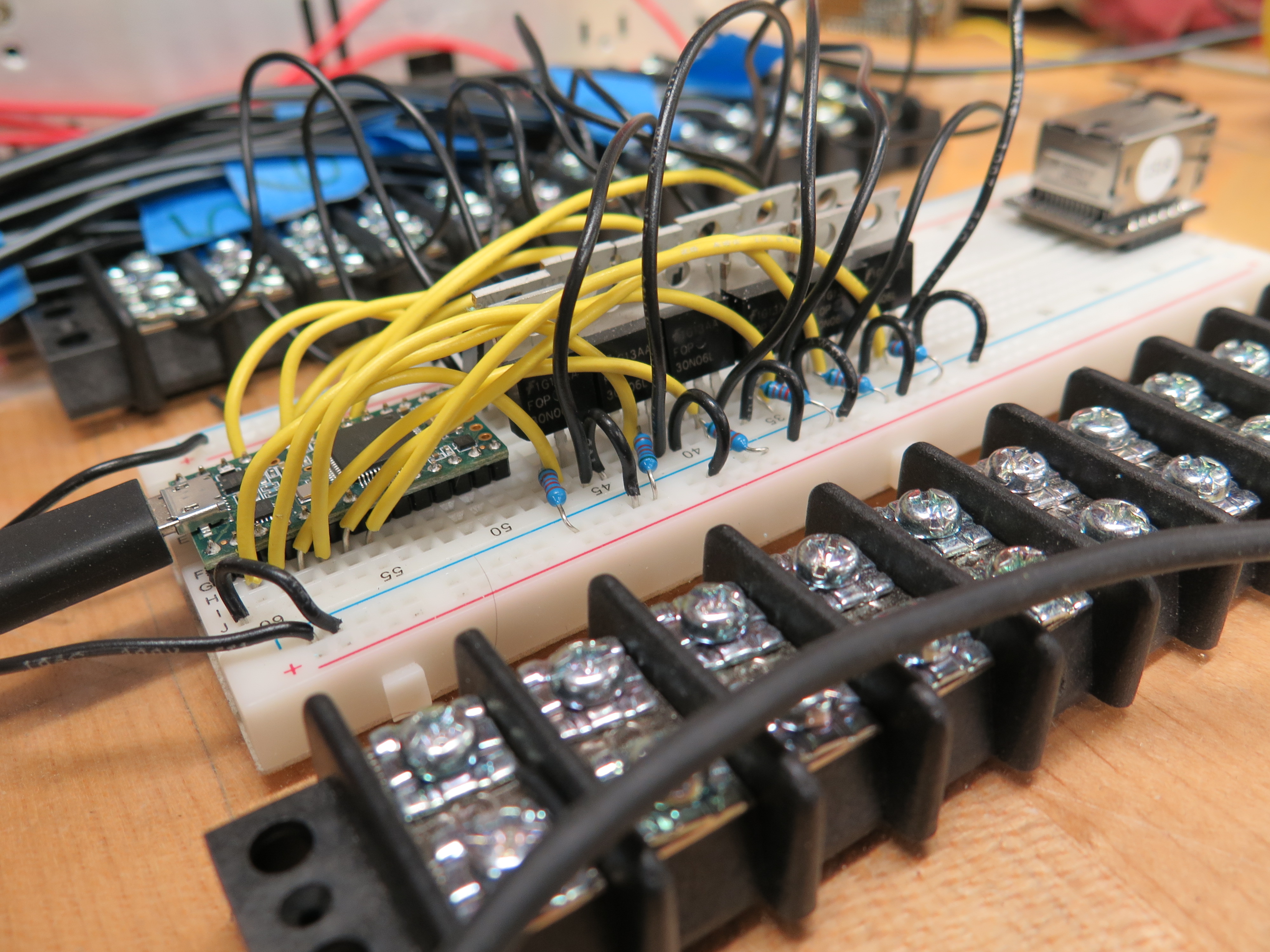
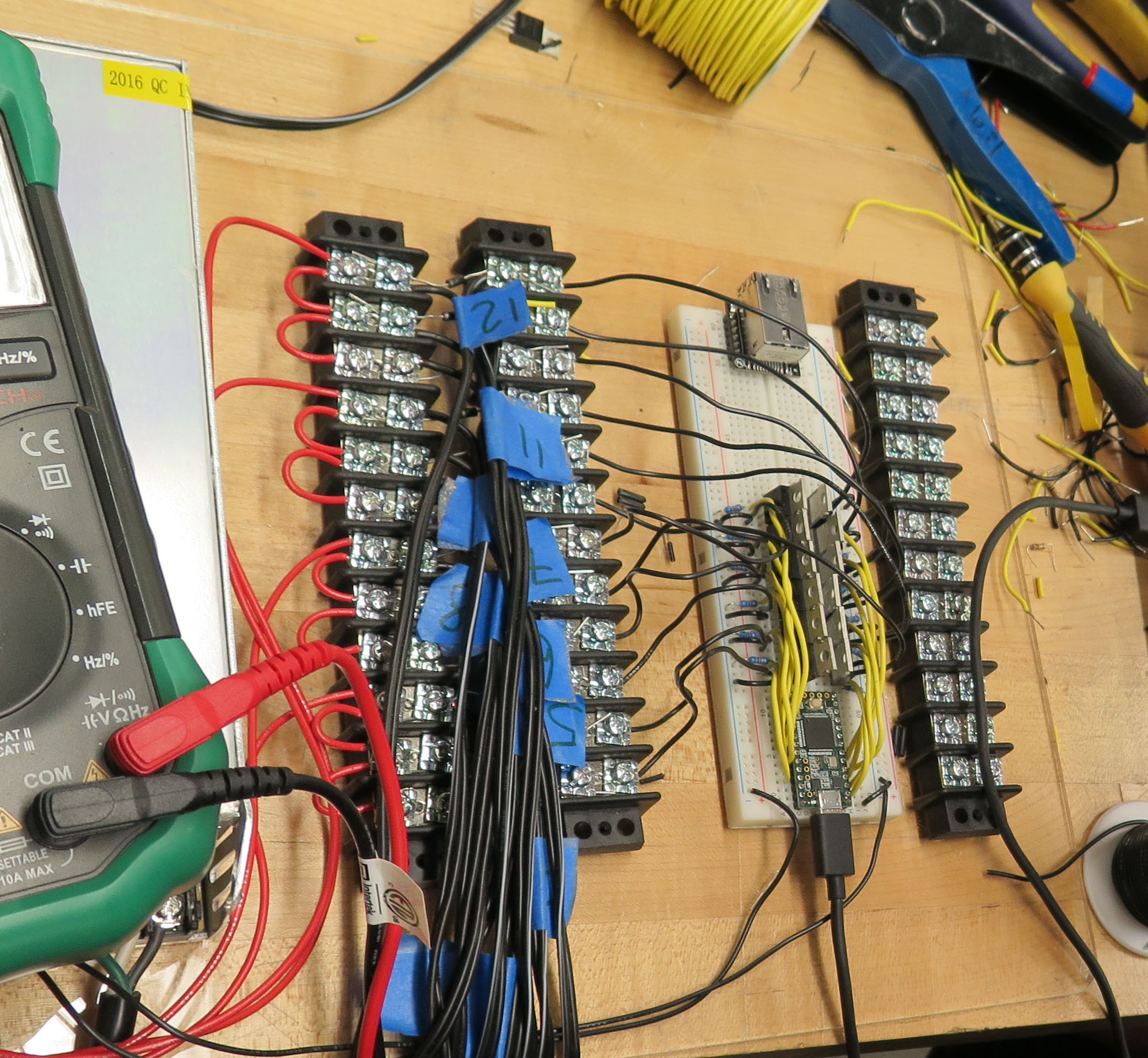
Due to the tight time constraints, I never got around to soldering this into a final board so all the pictures you can see here are the "prototype" version of the electronics.
Parts:
- Assembled Instrument
- 2 x 12 Terminal Block
- Perfboard/Breadboard
- 12V Power Supply
- 12 x 10K Resistors
- 12 x 1N4004 Diodes
- Hookup Wire
Steps:
- Work out how you're going to lay out your electronics. You are building the circuit in the breadboard diagram 12 times. The pins that you connect to on the Teensy can be changed in the code in the next step.
- Connect electronics.
- Each solenoid can be checked by connecting the gate pin of the corresponding MOSFET to 5V.
Programming
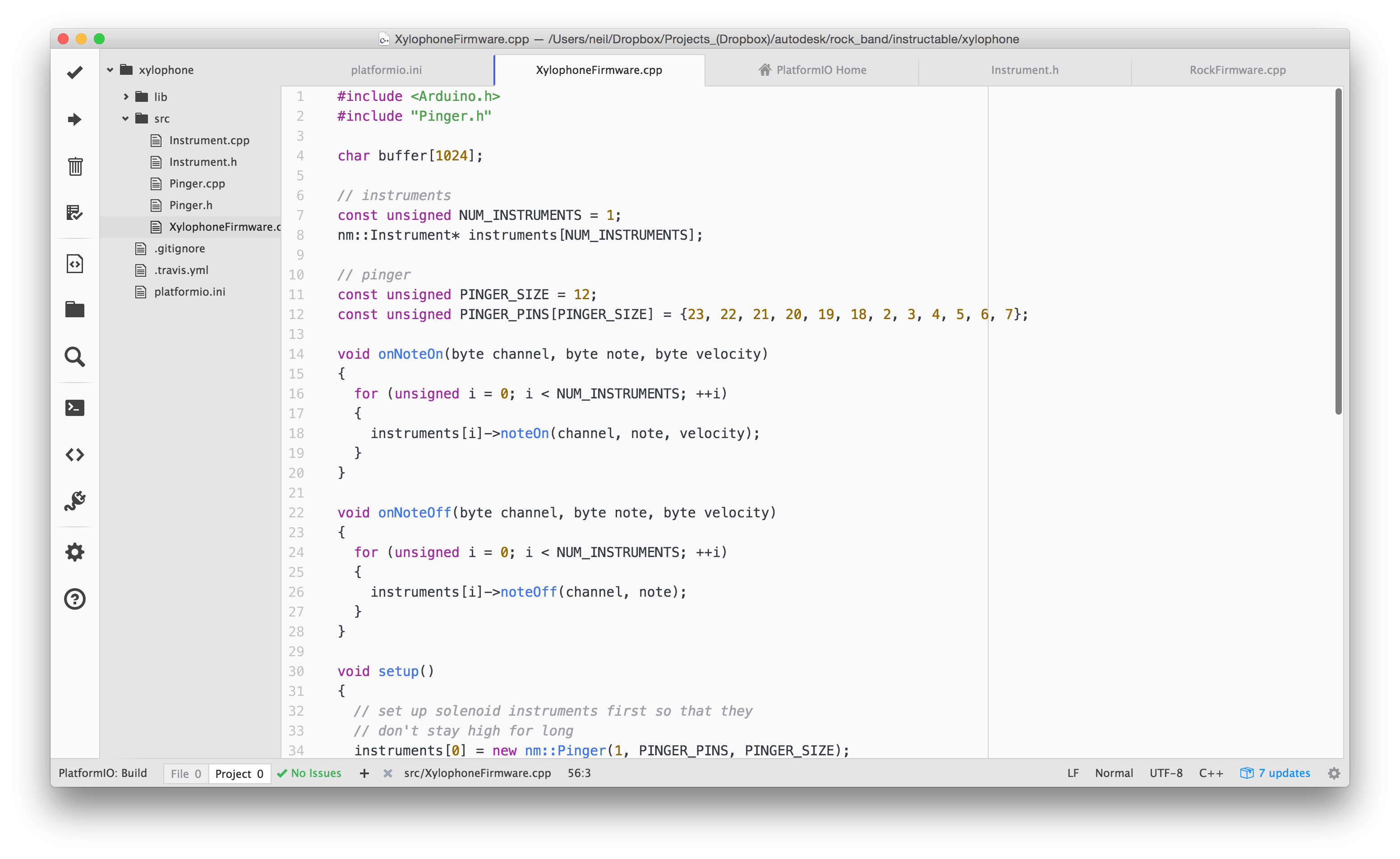
Parts:
- Computer
- PlatformIO IDE
- Micro USB Cable
Steps:
- Download and uncompress the zip file attached to this step.
- Install and start the PlatformIO IDE.
- Click Open Project on the PlatformIO home screen and then select the folder you unzipped previously.
- In XylophoneFirmware.cpp, adjust the PINGER_PINS variable to match the pins that you used.
- Connect the Teensy to your computer with the cable.
- Upload the firmware to the Teensy.
- You should now be to play the Xylophone by pressing keys a through to k.
- The firmware also makes the Teensy appear as a MIDI device so you can now play your instrument from any software that supports MIDI, for instance, Logic, Ableton or Cubase.
Downloads
Party

Congratulations, you have now completed your awesome instrument. The only thing left to do now is lie back and listen to the "soothing" tinkly sounds that your new creation makes.
This project would not have been possible without Autodesk's Pier 9 workshop and the amazing people that make the place what it is. Special thanks to Vanessa Sigurdson, Sherry Wong, Noah Weinstein, Josh Myers, Mary Elizabeth Yarborough, Paolo Salvagione, Charlie Nordstrom, Blue Bergen, Mei-Yen Shipek, Julie Kumar, Trent Still, Gabby Patin, my AiR cohort for all of their support and advice.