Jellyfish Kinetic Sculpture
by Printerforge in Workshop > 3D Printing
5710 Views, 80 Favorites, 0 Comments
Jellyfish Kinetic Sculpture
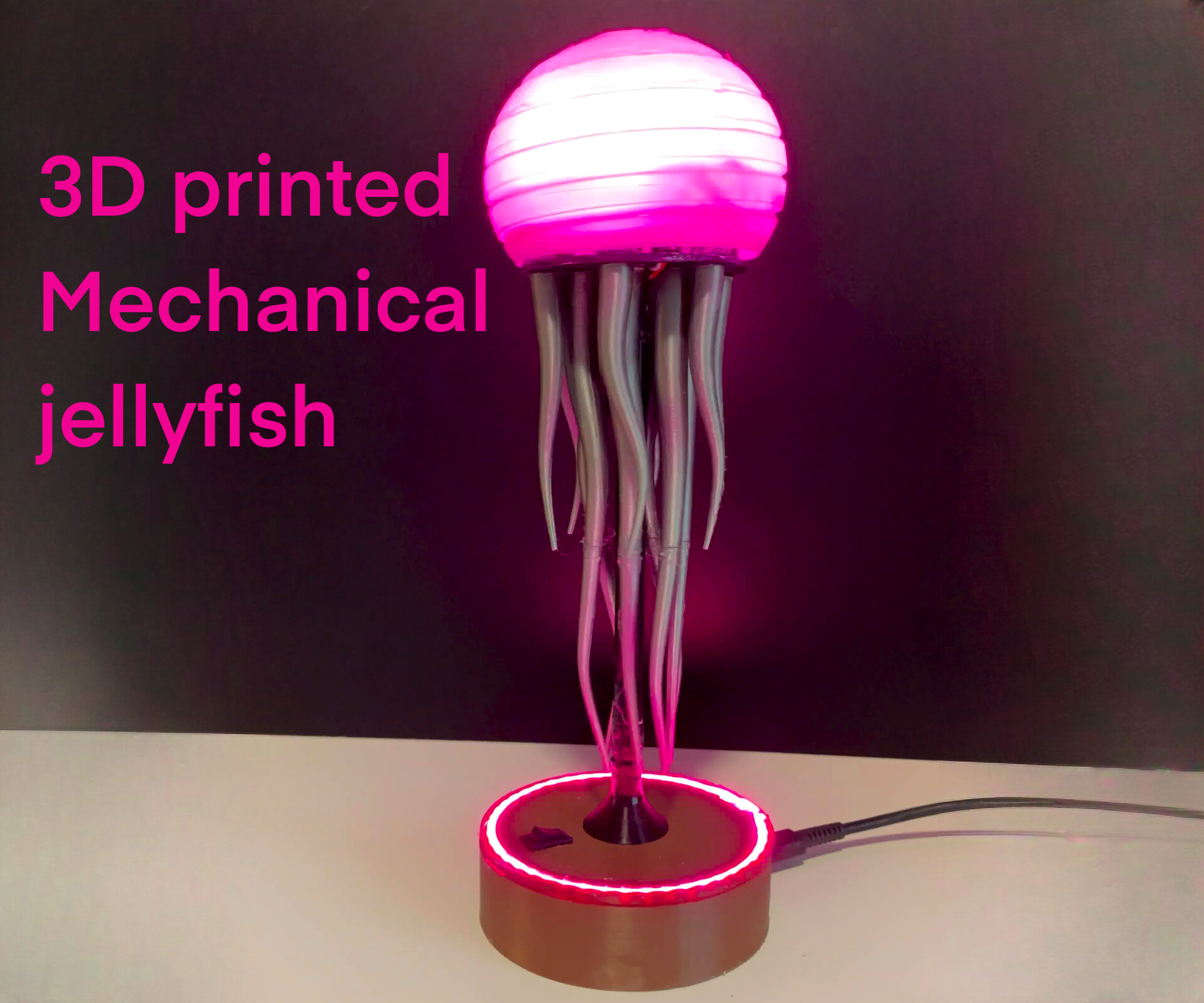
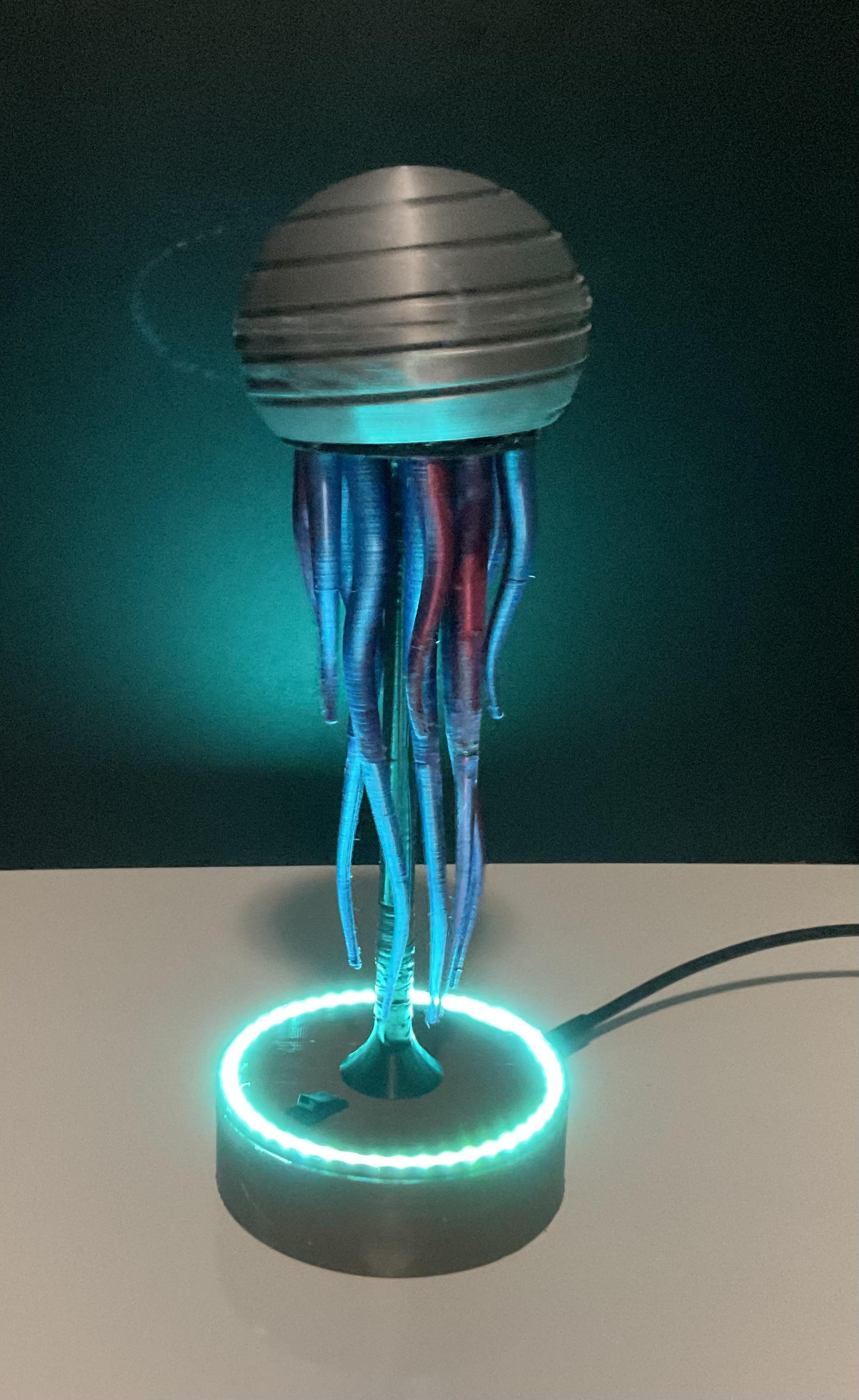
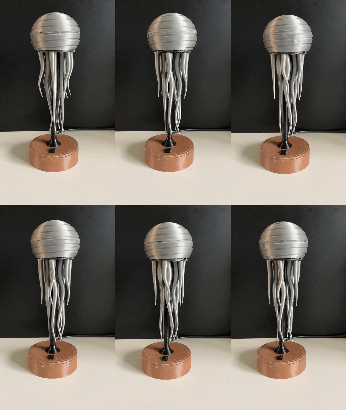
Welcome to this exciting DIY guide where we will create a captivating kinetic sculpture that not only mesmerizes the eye but also showcases the beauty of motion. This project is perfect for art enthusiasts, engineering hobbyists, and anyone who loves to blend creativity with technology. With just a few 3D-printed components, an Arduino setup, and some colorful LEDs, you can bring to life a stunning piece that dances gracefully in any setting.
Hi, my name is Ben and I’m 15 years old and I love to create 3D prints and electronics.
Why Build a Kinetic Sculpture?
I chose to build a kinetic sculpture that explores the intersection of art and engineering while providing hands-on experience in design, electronics, and programming. This project offers an opportunity to delve into mechanical principles, experiment with various materials, and understand how movement enhances artistic expression. It encourages creativity, allowing for customization in every aspect, from the tentacles to the lighting.
Project Features
- Dynamic Motion: The sculpture employs a unique gearing system that allows for smooth and satisfying movement, engaging viewers and drawing them in.
- Interactive Elements: Incorporate an IR remote control to change colors and effects on the LED strips, adding a dynamic lighting element to your creation.
- Minimal Noise: Special attention is given to reduce noise, ensuring the sculpture operates quietly, enhancing the peaceful ambiance of any space.
- Easy Assembly: With clear instructions and 3D-printable files, you’ll find it straightforward to construct your very own kinetic masterpiece.
- !This also doesn’t require any soldering! (Just know that you can’t use the LED strips)
- One of my main focuses was Customizable Design: Feel free to modify the sculpture’s tentacles, head, and rod, allowing for a personalized touch that reflects your artistic vision.
Let’s embark on this journey together and create a work of art that not only captivates but also inspires!
Supplies
Motor Only
- Tools:
- 3D Printer
- Soldering Kit (for connections)
- Hot Glue
- Materials:
- Filament
- Wire
- Electronics:
- Motor
- USB-C Power Supply
- Switch
- Capacitor (optional) (for smoothing voltage spikes)
Motor and LEDs
- Tools:
- 3D Printer
- Soldering Kit (for connections)
- Hot Glue
- Materials:
- Filament
- Wire
- Electronics:
- Motor
- USB-C Power Supply
- Switch
- Capacitor (optional) (for smoothing voltage spikes)
- Ws2812b (LED) Strip
- IR Receiver
- Microcontroller (Arduino Nano)
Background

After visiting an aquarium, I was captivated by the jellyfish on display. Inspired by their beauty, I wanted to bring a piece of that experience home. I checked the gift shop and found an incredible jellyfish sculpture, but when I saw the price—over $400—I knew purchasing it was not an option. Upon closer inspection, I realized that I could try making it myself.
That idea lingered with me, and when I came across the Art and Sculpture Contest, I recognized it as the perfect opportunity to challenge my skills in CAD (Computer-Aided Design) modeling. I set out to recreate the jellyfish sculpture, and to my delight, the final design turned out to be just as mesmerizing as I had hoped.
This project has been a fun and challenging journey, expanding my knowledge of Fusion 360 far beyond what I previously understood. Now, I'm excited to share with you not only how to assemble this sculpture but also the intricate 3D modeling process behind it.
Sketch/requirements
Design Requirements
As I transitioned from sketching to designing, I established several key requirements to guide the creation process:
- Aesthetic Appeal
- The sculpture needed to be visually stunning and elegant, drawing attention while maintaining a simple, clean form. The design aimed to balance complexity and minimalism, making it an eye-catching piece.
- Ease of 3D Printing
- I wanted the design to fit within the 220mm bed limit of standard home 3D printers, ensuring accessibility for most users. To save on print time and filament without compromising structural integrity, I optimized layer height, wall thickness, and used a minimal infill pattern.
- Ease of Construction
- The design had to be straightforward, allowing others to easily recreate it using my instructions and provided CAD files. I minimized complex joints and assembly steps, and by using screws instead of glue in certain parts, I maintained customizability and ease of modification or repair.
- Satisfying Motion
- Achieving smooth, satisfying motion was paramount. I focused on a perfect 1:1 gear ratio, resulting in balanced and fluid movement. This was essential for making the sculpture interactive and engaging.
- Minimal Noise
- A major goal was to keep the sculpture as quiet as possible. Given that gears are a central feature, I designed components to reduce friction and vibration, allowing it to be displayed in quiet environments without disturbance.
- Use of Gears
- Incorporating gears was crucial for adding a dynamic, mechanical element to the design. They served both functional and aesthetic purposes, facilitating motion while enhancing the sculpture's complexity and intrigue.
- Customizable
- Customizability was a key focus. I wanted users to easily change components like the head, tentacles, and rod, enabling experimentation with different aesthetics and functionalities. For example, I designed a hollow head to function as a night light and created dual-color tentacles for a vibrant appearance.
Power
I chose USB power for two main reasons: amperage and capacity.
Amperage
USB power supplies typically provide up to 2A (2000mA). This is important because:
- LEDs: Each LED draws about 30mA at 50% brightness. With 50 LEDs, the total draw becomes:
- 50 LEDs×30 mA=1.5 A50 LEDs×30 mA=1.5 A
- Motor: The motor draws 300mA (0.3A).
Combining these gives:
- Total Current Draw:1.5 A (LEDs)+0.3 A (motor)=1.8 A1.5 A (LEDs)+0.3 A (motor)=1.8 A
This total is well within the 2A capacity of the USB supply.
Capacity
USB power supplies not only provide sufficient amperage, but they also have decent capacity for sustained use. This means they can handle the maximum current draw from both the LEDs and the motor without issues.
Tolerance
The total current draw of 1.8A leaves a margin of 0.2A (200mA) under the USB's 2A limit. This tolerance is beneficial for several reasons:
- Safety: It prevents the power supply from being overloaded, avoiding overheating or failure.
- Efficiency: It allows stable operation without stressing the components.
By using USB power, the project can effectively manage the demands of both the motor and the LEDs, ensuring a reliable and enjoyable experience.
CAD Design Process
Once I had the design requirements and sketches in place, I started creating the 3D model in Fusion 360. My primary focus was on making the gears functional, minimizing noise, and ensuring the design could be easily printed and assembled.
Gears/printing
Gear Types
Before diving into 3D modeling, it's important to understand how gears work. Think of gears as the wheels of a bicycle chain; instead of moving a bike, they help move parts of machines. Gears fit together like puzzle pieces, with teeth that interlock, allowing them to spin and create smooth motion. Let’s explore what makes gears so fascinating!
What Are Gears?
Imagine two round wheels with teeth on their edges. When one wheel spins, the other one does too. That’s how gears operate! They facilitate movement in machines by enabling spinning parts to work together. As one gear turns, its teeth push against the teeth of the next gear, creating motion.
Types of Gears
Just like there are different tools in a toolbox, there are various types of gears, each designed for a specific purpose:
- Spur Gears
- These are the most common type of gears. They have straight teeth and look like the gears you’d see in cartoons. Spur gears work best when positioned side by side, turning in opposite directions.
- Helical Gears
- These gears are a bit more sophisticated. Their teeth are angled, allowing them to glide against each other rather than just pushing. Think of helical gears as the smooth dancers of the gear world—they operate quietly and are better suited for complex movements.
- Bevel Gears
- If you need to turn a corner while spinning, bevel gears are the solution. They connect two gears at an angle, allowing for direction changes in motion.
- Worm Gears
- These gears resemble a spiral staircase and excel at slowing down motion. When a worm gear spins, it slowly turns another gear, making it ideal for creating steady, controlled movements.
Gear Parameters
When creating gears, there are several important factors to consider, akin to the "rules" that determine how gears will look and function. Let’s break them down:
- Standard
- This is like choosing a language for your gears—imperial or metric. I usually opt for metric measurements, as most motors and parts I purchase are measured in millimeters. It simplifies the design process, much like using centimeters instead of inches.
- Pressure Angle
- Think of this as how two gears "hold hands" when they meet. The pressure angle is the angle of the teeth at their contact point. The most common angle is 20 degrees, which ensures that the gears work well together and maintain a strong connection, much like a firm handshake.
- Module
- This term refers to the size of the gear teeth. It’s like deciding how big each bite is when eating. A larger module means chunkier teeth, while a smaller module results in finer teeth. The module helps determine the overall tooth size.
- Number of Teeth
- This is simply how many teeth a gear has. Gears with different numbers of teeth will turn at different speeds. For example, if one gear has 12 teeth and another has 60, the smaller gear must spin five times to turn the larger one once. This relationship is known as the gear ratio and helps control the speed of movement.
- Backlash
- Think of backlash as the "wiggle room" between two gears. It’s the small gap that allows gears to move smoothly without getting stuck. This extra space acts like a cushion, ensuring that everything turns freely.
- Root Fillet Radius
- This parameter refers to the strength at the base of each tooth. Just like a tree needs strong roots to stay upright, gear teeth require additional strength at their base. The fillet is a curve at the bottom of the tooth that reinforces its strength.
- Gear Thickness
- The thickness of a gear is similar to stacking coins. For instance, if a gear is 10mm thick, it’s like having a stack of coins that is 10mm tall. Thickness can affect the gear's strength and durability.
- Hole Diameter
- This is the central hole of the gear, where it attaches to a shaft or axle—similar to the hole in a donut. The hole diameter must match the size of the axle it will fit onto.
- Pitch Diameter
- The pitch diameter is like the "sweet spot" where the teeth of two gears engage. It’s not the widest part of the gear, but it’s crucial because it’s where the teeth connect and work together effectively.
Modeling
In this step, I’m going to show you how I modeled my jellyfish sculpture, focusing on three main parts: the gears, the tentacles, and the head.
1. Gears (background)
- Choose the sketch idea: I picked a design that used 12 tentacles and minimized the number of gears, which helps reduce noise and friction.
- Use constraints in Fusion 360: Instead of manually calculating the size, I used Fusion 360’s constraints. Constraints are rules you apply to a sketch to control the shape and size of your design. Think of it like giving your sketch strict instructions on how it should behave. For example, a constraint might say that two circles must always be the same size or that they must touch without crossing.
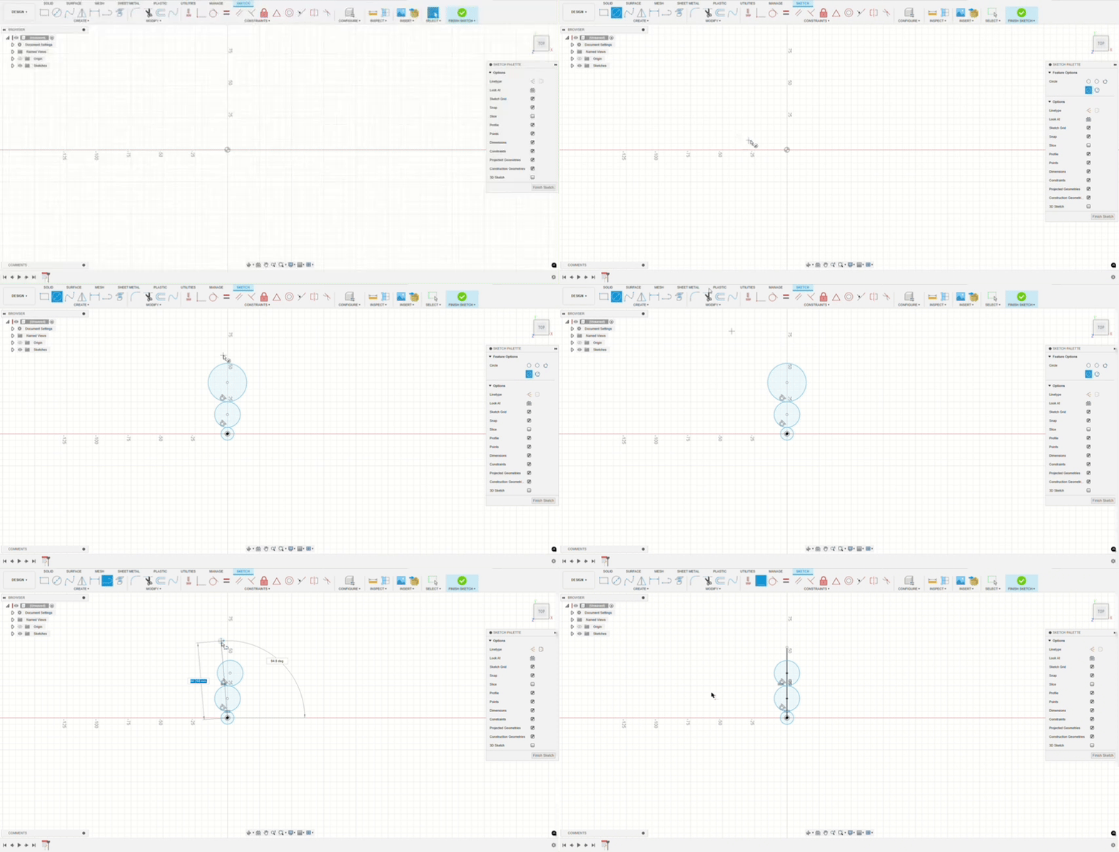
Modeling the sketch:
- Draw three circles: Stack them on top of each other.
- Apply the tangent constraint: This makes the circles touch at a single point but never cross.
- Make the top two circles equal: Set their size to be the same.
- Add a center line: Draw a line from the center of the circles to the outer edge.
- Draw a larger outer circle: This circle surrounds the smaller ones and is tangent to them.
- Set a sketch dimension: I set a dimension of 65mm, which was the maximum size I wanted the gearbox inside the head to be. When the sketch turns black, it means it’s fully constrained (all dimensions and shapes are locked into place).
- Convert circles to construction lines:
- Construction lines in Fusion 360 are guides that help you organize your sketch without creating solid geometry. Think of them as a dotted outline, like a pencil sketch before going over it with a marker. They’re like scaffolding you can use temporarily while you build the actual shape.
- Inner circle: Now, I designed the smaller inner circles inside the circles. This will become the threads.
- Set dimensions: Set the dimensions to what I needed them to be. This further constrains the sketch, making it easier to control.
- Visualizing Constraints: It can be hard to see all the constraints in a complex sketch, so I created a visual guide that outlines them. (These are called driven sketch dimensions—these dimensions don’t control the shape but instead reflect how other parts of the design affect it. They are shown in parenthesis)
1.2. Modeling the Gear
- Use Fusion 360’s gear script: A script is like a mini-program inside Fusion 360 that performs tasks automatically based on certain parameters you provide. In this case, it generates gears for you, doing all the math so you don’t have to.
- Switch from spur gears to helical gears: I initially used spur gears but faced problems with noise and friction. I switched to helical gears, which have angled teeth that mesh more smoothly.
- Open the helical gear add-on and adjust the settings: (I want to give a huge thanks to Ross Korsky for providing this add on for free)
- Set the helix angle to 45 degrees: This is an optimal angle for 3D printers.
- Ensure the gears have the same pitch diameter: This is critical for proper meshing. (Shown with red circle)
- Set the module to greater than 0.75: A higher module ensures the teeth are big enough for easy 3D printing.
1.3. Handedness
- Change the Handedness: Handedness refers to the direction the gear teeth lean when placed flat. One gear might lean left, while the other leans right. This allows them to mesh together smoothly.
- Example: Think of the teeth like ramps on a conveyor belt: the direction the ramps lean determines how they interlock with the next belt.
- Maintain the 1:1 ratio: Both gears will rotate at the same speed, so you don’t need to adjust other settings.
2. Tentacles (Background)
2.1. Sketching the Tentacles
- Draw a large circle at the base: Start with an 8mm-wide circle at the base of the jellyfish.
- Create a construction plane: Place the plane 150mm below the base. This will set the maximum height of the tentacle.
- Draw a smaller circle on the plane: Make the second circle 3mm wide.
- Add a spline: The spline is a curvy line that connects the two circles and determines the shape of the tentacle.
2.2. Lofting the Tentacles
- Use the Loft Tool: This tool connects the two circles and generates the tentacle’s 3D shape.
- Add rails for lofting: Rails act as guides, helping shape the tentacle precisely.
- Turn on centerline lofting: This option helps the loft flow smoothly, preventing jagged edges. By default, lofting uses two rails, but centerline lofting uses just one, allowing for a more fluid transition.
3. Head (Modeling)
- Create two sketches: One sketch defines the spiral path, and the other defines the shape of the spiral.
- Use the Sweep Tool: This tool follows the spiral sketch to create a path in the head.
- Cut the model: This tool creates a 2D cut that follows the spiral path, making the head appear as if it’s spinning.
- Pipe the path: Now that we have a path you can use the pipe tool to follow and cut into it.
After completing the jellyfish sculpture model, I was thrilled with how all the components came together seamlessly. The gears functioned smoothly, meeting my goal of reducing noise and friction while maintaining a 1:1 gear ratio. The tentacles, with their elegant curves and smooth lofting, perfectly mimicked the organic movement I was aiming for. The spiral on the head added the mesmerizing effect I envisioned, making the model visually dynamic. Overall, the 3D model not only met the technical requirements but also captured the aesthetic qualities that inspired this project.
Downloads
Prototype 3d Printing
To save time and reduce material cost, I use what I call "prototype settings" when printing early models. These settings help achieve faster prints while still maintaining the basic structure of the part. Here’s how:
- Increase Layer Thickness:
- Doubling the layer thickness can cut print time in half. For example, a 24mm tall model with 0.12mm layers requires 200 layers, but with 0.24mm layers, it only needs 100 layers, speeding up the process.

- Reduce Wall Thickness (Perimeters):
- Walls or perimeters are the outer layers that form the print’s exterior. Reducing the number of walls or making them thinner uses less filament and decreases print time, though it slightly weakens the print.

- Reduce Infill:
- Infill is the internal structure of the print. For prototypes, you only need enough to keep the model stable.
- Lightning Infill:
- This pattern adds material only where it's needed for support, using a lightning-bolt shape. It's a great way to cut down on filament while maintaining structural integrity.

These settings make it faster and cheaper to print test models while still keeping the essential design intact.
Assembly
3D Printing
Before assembling the jellyfish sculpture, let's focus on 3D printing settings. These adjustments are recommended to help reduce friction, noise, and post-processing, but they aren't strictly necessary depending on your specific goals or hardware capabilities.
Parts to Print
- 6x 10L
- 6x 10R
- 6x tentacles_1_8_2
- 6x tentacles_1_8_1
- 6x tentacles_1_4_1
Settings for Gears/Gearbox:
To ensure smooth meshing, durability, low friction, and quiet operation, consider the following settings:
- Low Layer Height: It's recommended to set to the smallest layer height (0.12mm). This finer resolution ensures the gears will mesh smoothly, reducing noise. You can use a higher layer height if precision isn't critical, but this might increase noise and wear over time.
- X-Y Contour Compensation: Adjusting this setting is recommended if your printer’s tolerances require it. The model already has a built-in tolerance of 0.2mm, but if needed, increasing the compensation (by around 0.1–0.2mm) can improve the fit and reduce friction. You may skip this if your prints are already dimensionally accurate.
- Ironing: Enabling ironing for the gear’s top surface is recommended. This feature smooths out the top layers, reducing friction on the gear teeth. If you don't have issues with friction, ironing isn't strictly necessary.
- Walls/Perimeters: Setting the walls/perimeters to 3-4 is recommended for durability, but since these gears aren't under high speed or torque, fewer walls can be used if needed. Three walls are generally sufficient, and four provide extra strength if you want added durability.
- Other Parts: Non-gear components can usually be printed with default settings unless specific adjustments are needed for your setup.
Assembly
Now, let's assemble the sculpture! If you're adding LEDs, follow the steps below. If not, skip the LED wiring section.
LED Wiring (Optional)
- Cut the LED strip to match the circumference of the inner circle base.
- Soldering Wires: Solder three wires—one for ground (black), one for power (red), and one for signal (yellow or your choice).
- Peel back the adhesive strip slightly to expose the copper pads on the LED strip.
- Apply flux (this is recommended, but not required) for smoother connections.
- Use tweezers to hold the wire in place while soldering.
- Stick the LED strip to the base. You don’t need to glue it but you can there’s really no point as we will fill it in with glue later.
- Gluing LEDs:
- Align the Inner Ring: Place the inner ring on the base, routing the wires through the small hole in the base.
- Gluing: Avoid gluing the inner ring until alignment is perfect. Screw the rod in and add a small dab of glue to secure the outer ring once positioned. Then unscrew the rod.
- Wiring: Use the provided circuit diagram to connect the positive and negative leads.
- Cut two wires, each 23cm (≈9.5in) long, for powering the motor at the top.
- Wire the switch, USB connector, LED strips (if using), and provide power wires for the microcontroller (Arduino).

Assembling the Rod
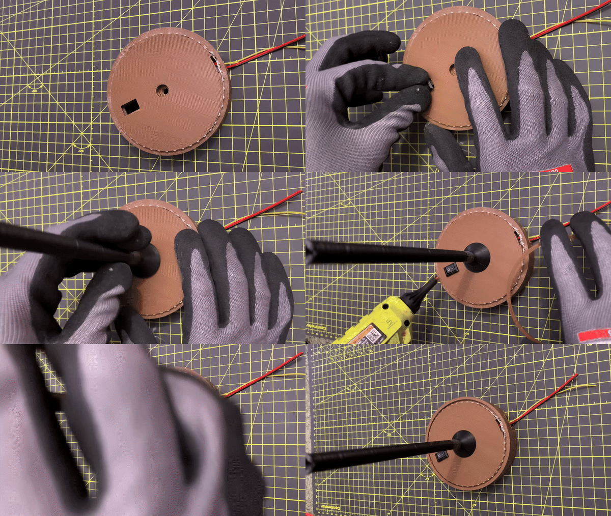
- screw the Rod to the bottom gearbox, making sure it’s straight and aligned.
- Glue the rod in place if you want to but that will prevent you from changing the rod.

- Screw the Rod to the Base: Route the wires through the hole and conduit, ensuring they don’t interfere with the gears.
- Wire Routing: Pull the wires through the conduit and into the next hole. The wires are outside the gear area to avoid interference with the moving parts. The head will also cover the wires, so they won’t be visible either.


Tentacles
- Dry Fit the tentacles before gluing them. This ensures everything is properly aligned before making it permanent, and is recommended for accuracy.

- Gluing: Once aligned, glue the tentacles in place.

Gears
- Insert a Middle Gear and screw the tentacle in place. Repeat this for each gear until you’ve assembled all 12 tentacles.
- Outer/middle Gears: Add the outer and middle gears and make sure each meshes properly with the others.
- Sun Gear: Finally, add the sun gear to the center.
Lubrication
If available, apply lubrication (preferably grease) to reduce friction and noise, and to prolong the lifespan of the gears. While lubrication is recommended, it's not mandatory. You can use WD-40 although, it’s not ideal for 3D-printed parts. Grease works better because it forms a thin protective layer between surfaces.
Top Gearbox and Motor
- Apply Glue in each support hole, except where the motor wires are located, and attach the top gearbox.
- Motor Installation:
- Align the motor’s shaft with the sun gear, ensuring the flat part of the shaft fits into the gear.
- After the motor is connected, dry fit the cover before gluing it in place.

- Soldering the Motor: Cut the motor wires to the correct length so they don’t interfere with the heat that builds up in the motor
- Optional Capacitor: Adding a 104 capacitor can help smooth out voltage spikes, though it's optional and not required.
Only motor: If you chose not to do LEDs you can simply place the head ontop and glue the base, otherwise we can add the LEDs onto the top to light up the head!
LEDs (top)
- Now if you want to add lights to the top solder the LEDs then stick them onto the holder and finally wire it up to the the signal wire and motor wires.
The assembly is almost done, now we just need to upload the code and glue the bottom!
Assembly (Code) - Customize/Test
Understanding the Code for Controlling LED Strips
This code helps you control two LED strips using a remote control. It allows you to change the colors of the lights and turn them on or off. Here’s a breakdown of how it works, step by step:
What Is in the Code?
1. Include Libraries
- Libraries: The code uses special tools (called libraries) that help the Arduino communicate with the LED strips and the remote. Think of libraries as pre-written instructions that save time.
2. Setting Up the Arduino
- Pin Connections: The code tells the Arduino which pins to use for the LED strips and the remote. Pins are like small connectors on the Arduino board where you attach wires.
- LED Count: It specifies how many LEDs are in each strip. This is important because it helps the code know how many lights to control.
3. Understanding the Remote Control
- IR Values: Each button on the remote sends a unique signal, like a secret code. The code assigns these codes to different actions, so when you press a button, the Arduino knows what to do.
4. Colors Defined
- Color Values: The code includes specific color codes (called RGB values) for various colors. RGB stands for Red, Green, and Blue, and these colors mix together to create different light colors.
5. How the Code Works
- Setup Function: This part of the code runs once when you turn on the Arduino. It sets up the LED strips and the remote control so they are ready to use.
- Loop Function: After the setup, the code enters a continuous loop. This means it keeps checking for signals from the remote. When you press a button, it detects the signal and changes the color of the LEDs accordingly.
6. Changing Colors
- Color Setting Function: This is a special function in the code that tells all the LEDs to change to a specific color when a button is pressed.
Upload, Wiring, and Assembly
- Upload the Code: Upload the provided code to your Arduino using the Arduino IDE.
- Wiring:
- Connect the LED strips to the correct pins on the Arduino (Pin 6 for the bottom strip and Pin 7 for the top strip).
- Connect the IR receiver to Pin 2 on the Arduino.
- Double-check all wiring to ensure the correct connections.
- Warning: Double-check the wiring as incorrect connections may prevent the project from working, could fry your Arduino, or even cause other problems.
- Gluing:
- Glue the Bottom of the base to the top to secure everything in place.
- Using the Remote:
- Once everything is connected and the code is uploaded, you can use the remote to control the LEDs.
- Pressing different buttons will allow you to change the LED colors or turn them off.
- Debugging:
- If something isn’t working, the code is programmed to print out information to the Serial Monitor.
- The Serial Monitor helps you see what the remote is sending, so you can understand which button corresponds to which action. This makes troubleshooting easier.
Customization
This project allows you to make changes easily. Instead of using glue, which would make parts permanent, I used screws. This way, you can:
- Change the Head and Tentacles: You can swap out the head and tentacles for different styles or colors. For example, I made a hollow head that can act as a night light.
- Choose Your Colors: The rod that connects the parts can be any color you like. I chose black, but you can pick whatever fits your style.
Noise Considerations
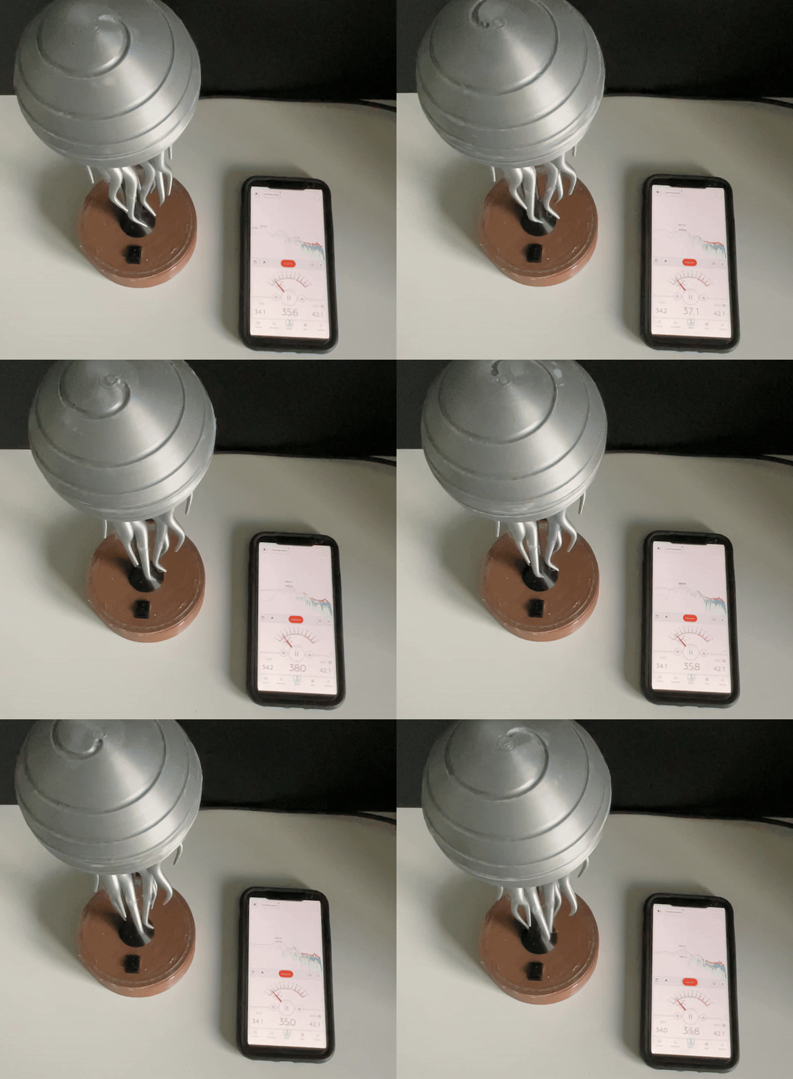
When designing my jellyfish sculpture, one of my priorities was to make it as quiet as possible. Noise levels can affect the experience of enjoying the sculpture, especially in peaceful settings. To gauge how quiet my design was, I decided to measure sound levels using my phone. While a professional microphone or sound meter would provide more accurate results, my phone was sufficient for getting a rough idea.
I achieved an average sound level of 33 dB, which is quite low. For context, this is similar to the sound of a whisper or the quiet ambiance of a library, making it suitable for tranquil environments.
Understanding Decibels
Decibels (dB) are a unit used to measure sound intensity. Here’s a simple breakdown of what different dB levels represent:
- 30 dB: Quiet library
- 33 dB: Whisper or rustling leaves
- 60 dB: Normal conversation
- 70 dB: Office noise
- 50-70 dB: Air conditioning unit
A sound level of an average of 33 dB indicates that the sculpture operates quietly, ensuring it can be enjoyed without distraction.
Reducing Noise Further
To make the sculpture even quieter, I considered several strategies:
- Use Ball Bearings: These can reduce friction between moving parts, leading to smoother operation and less noise.
- Different Gear Types: Experimenting with various types of gears can result in smoother movement. Some gears are designed to minimize noise while still being effective.
- Quieter Motor Options: Selecting a quieter motor could significantly decrease the overall sound level. For instance, stepper motors are known for their smooth operation and can be quieter than traditional motors.
By implementing these changes, I could further enhance the serene experience of interacting with the jellyfish sculpture.
Downloads
Next Step/conclusion.
I really enjoyed this project and learned a great deal throughout the process. There’s not much improvement needed on the design itself; the only noise primarily came from the motor, not the 3D-printed gears. With more resources, I might consider using ball bearings to enhance the sculpture's movement, as they would further reduce friction for smoother operation. Additionally, resin-printed gears would offer superior quality and strength, and they can be printed at smaller scales, providing more design flexibility. If I had more time in CAD, I could refine the design even further.
Another idea for improvement could be to use a stepper motor, which would provide more torque and operate more quietly than the current motor.
I want to express my gratitude to everyone who took the time to read this. A special thanks to Autodesk for providing Fusion 360, which is free for students and has been invaluable for my modeling work. Throughout this project, I deepened my understanding of modeling and gear mechanics, knowledge that will benefit me in future engineering endeavors.
If you have any questions, comments, or ideas, I would love to hear from you! I would love to see if you guys have any ideas or if you guys create this yourselves. Again, thank you for reading this all the way through as I had lots of fun making and writing this out!
