MeLion Growbox System
by Matejic in Circuits > Microcontrollers
15481 Views, 284 Favorites, 0 Comments
MeLion Growbox System
Acknowledgment
First of all I would like to thank Audrey and Penolopy Bulnick for their outstanding efforts to help me get my Intel Edison kit despite all of the troubles I’ve had with customs service in my country.
If it was not for them, I probably would not have had this kit delivered to me.
Basic description
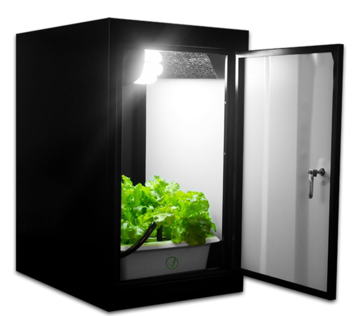
MeLion GrowBox is a system that automates some of the operations required to grow plants indoor using a growbox. A grow box is a partially or completely enclosed system for raising plants indoors or in small areas. Grow boxes are used for a number of reasons, including lack of available outdoor space or the desire to grow vegetables, herbs or flowers during cold weather months. They can also help protect plants against pests or disease.
Grow boxes may be soil-based or hydroponic.
It automates the following operations:
1. Irrigation
2. Heating
3. Lighting
Description of the system
As previously said, MeLion GrowBox is used to automate operations of a grow box. To achieve this it uses a variety of sensors to get the current state of the most important parameters – moisture, temperature and light. Using those parameters together with custom set breakpoints the system turns specific features on or off. For example, you can set the desired moisture level of the soil and when the level drops below it, controller activates the irrigation pump until the level is over the breakpoint.
Likewise, you can set a pair of breakpoints (low and high) for air temperature. When temperature drops below the low breakpoint the heating is turned on until the temperature is over the high breakpoint.
The goal of this system is to minimize the need of manual overseeing and operation of a growbox and also to achieve ideal conditions for the plant at all times.
Components
Components used:
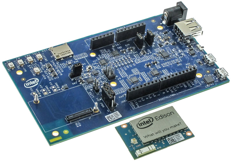
1. Intel Edison/Arduino Breaking Board
2. Grove Moisture sensor
3. Grove Digital Light Sensor
4. Custom built temperature sensor
5. Grove 6V mini water pump
6. Custom built relay module board with 3 relays
7. Flat foil heater
8. LED strips
9. Growbox
10. Android phone with Blynk app
Making Custom Intel Edison Shield With Transfer Methode
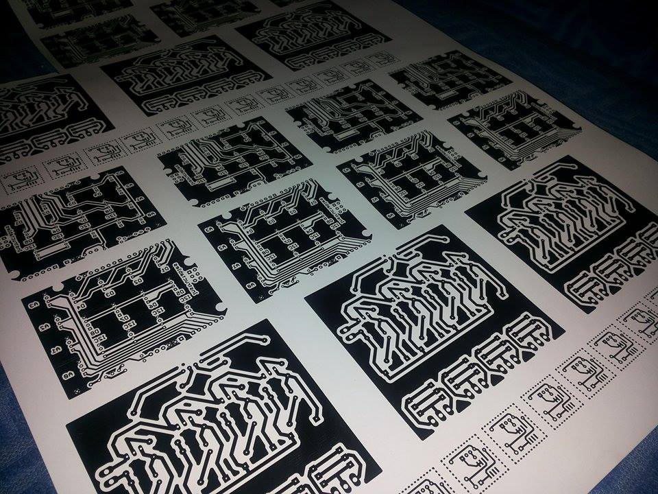
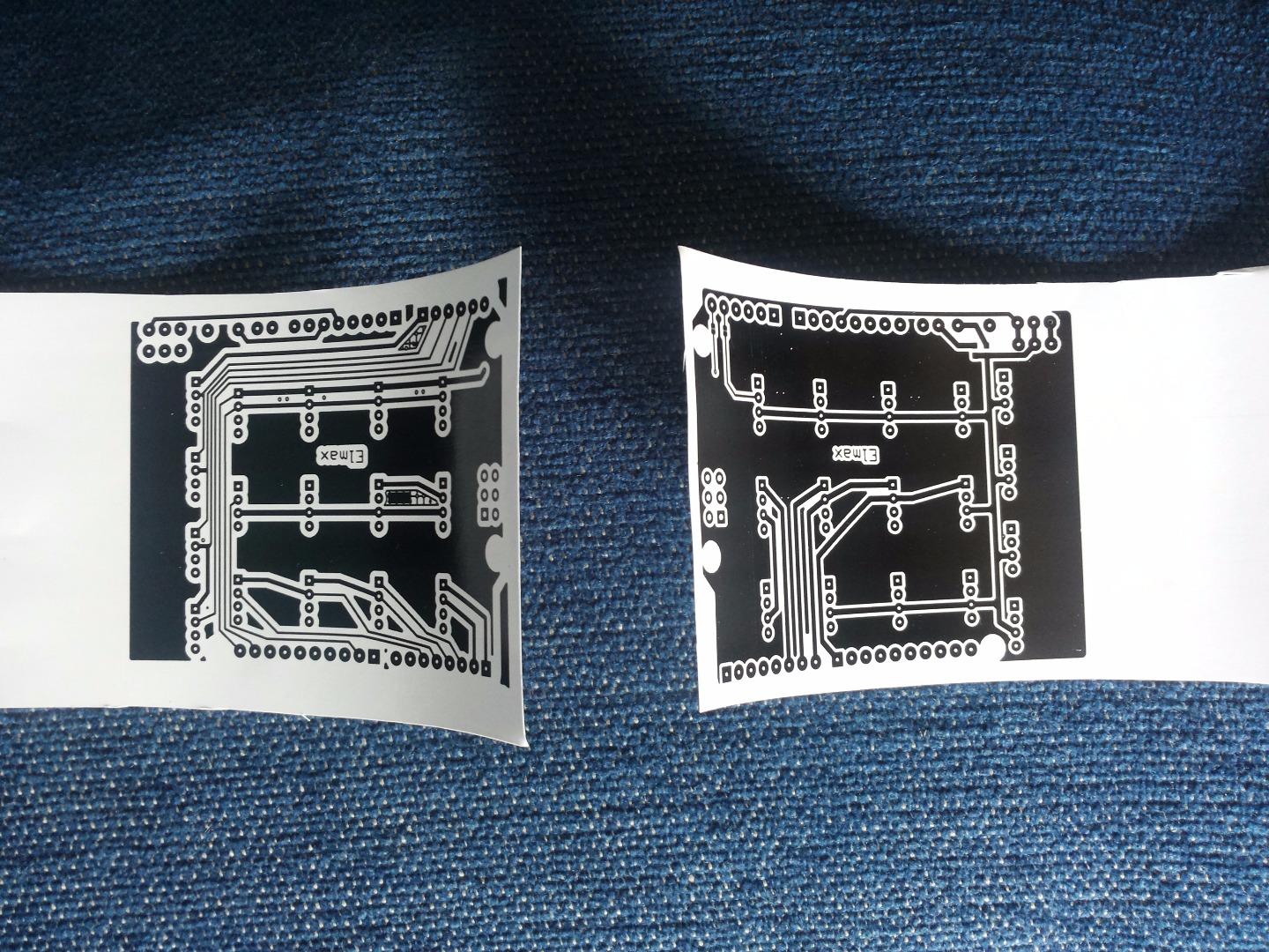
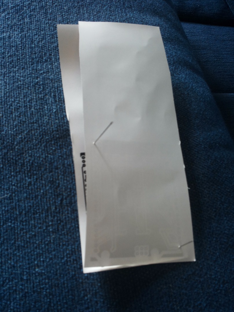
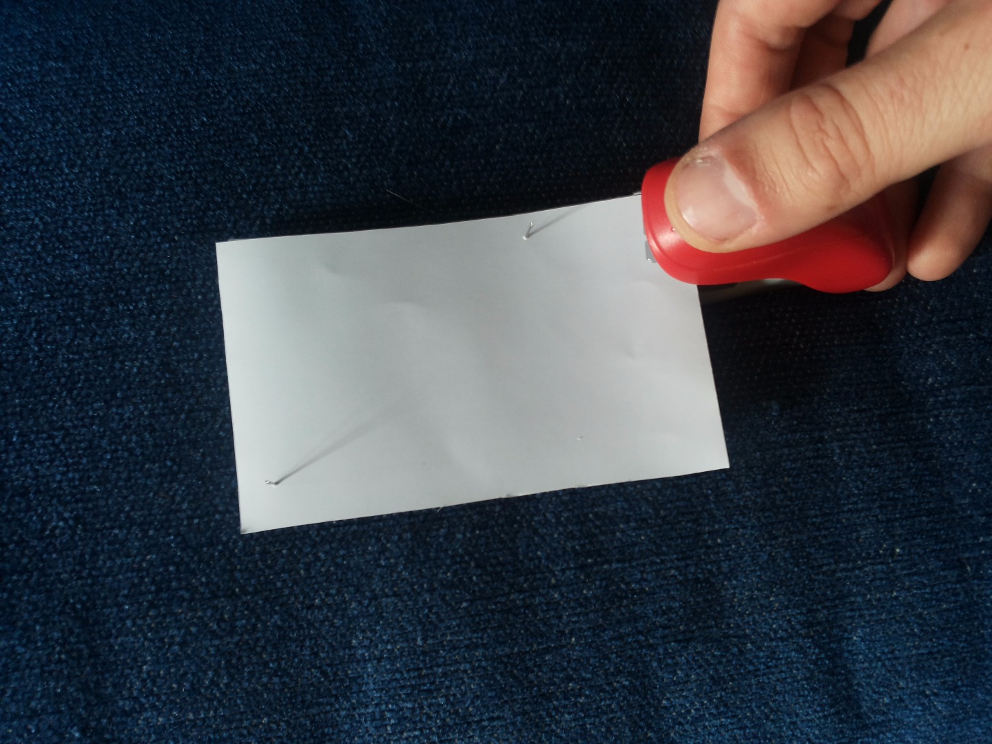

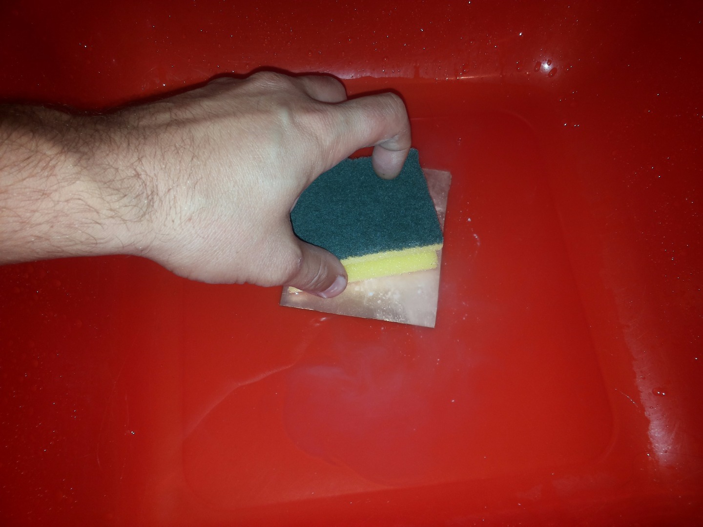
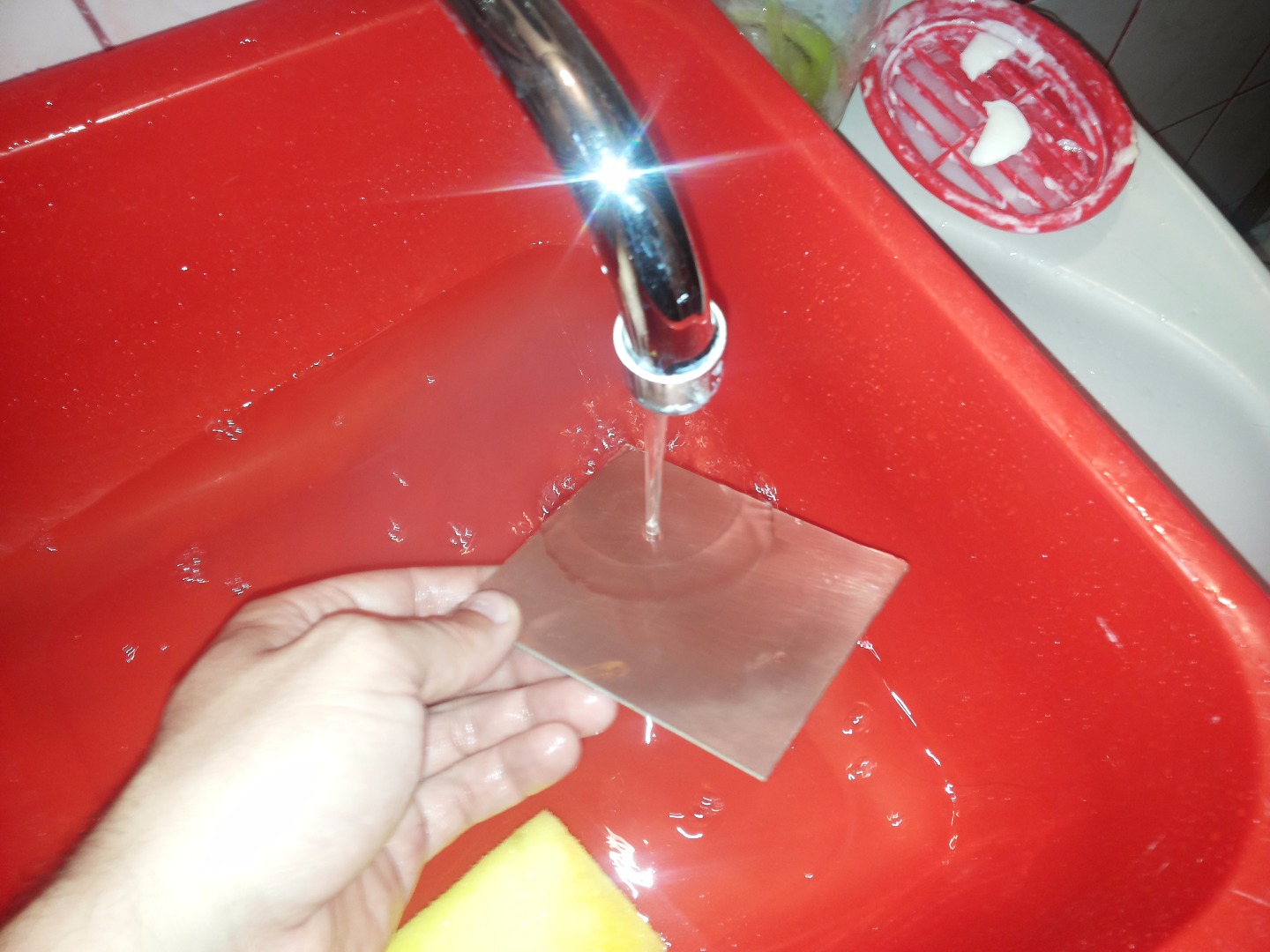
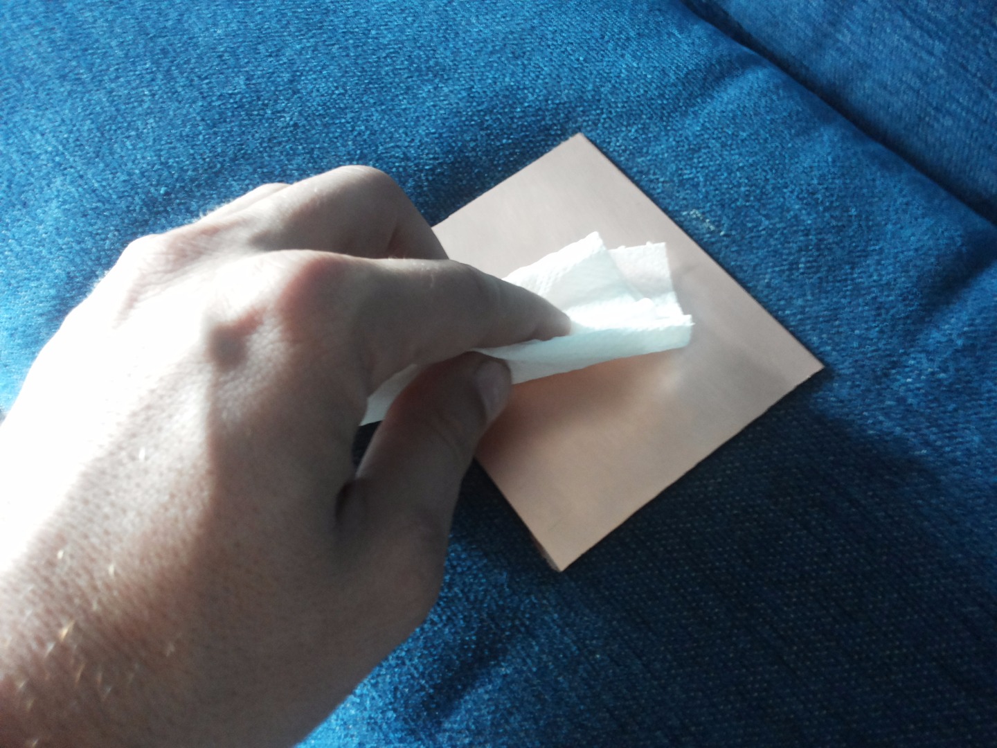
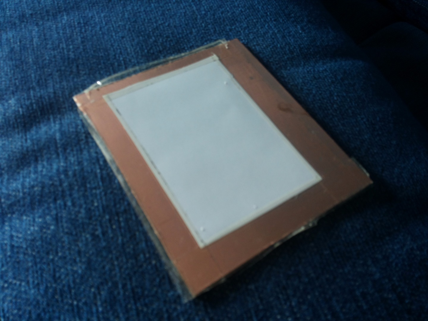
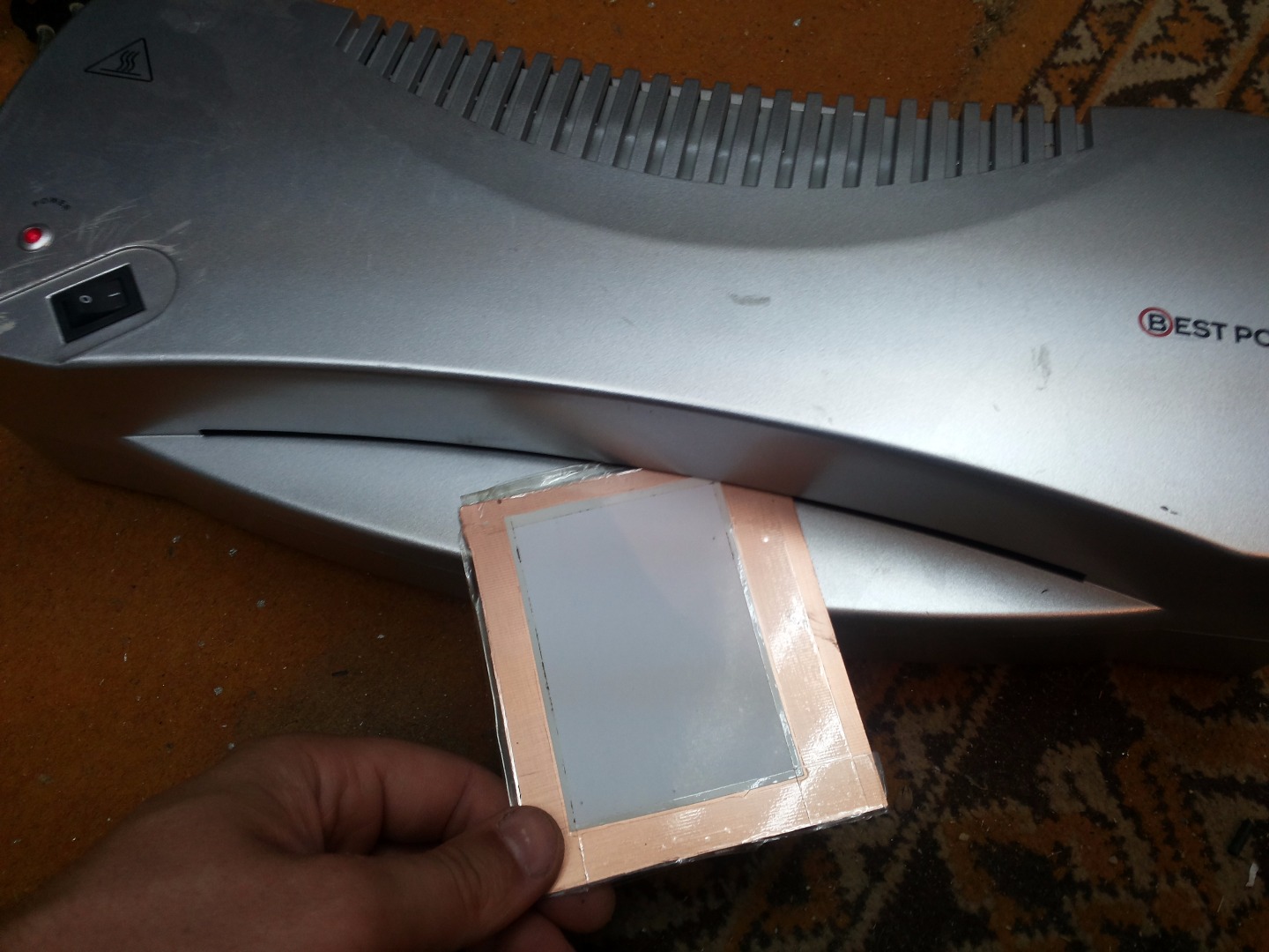
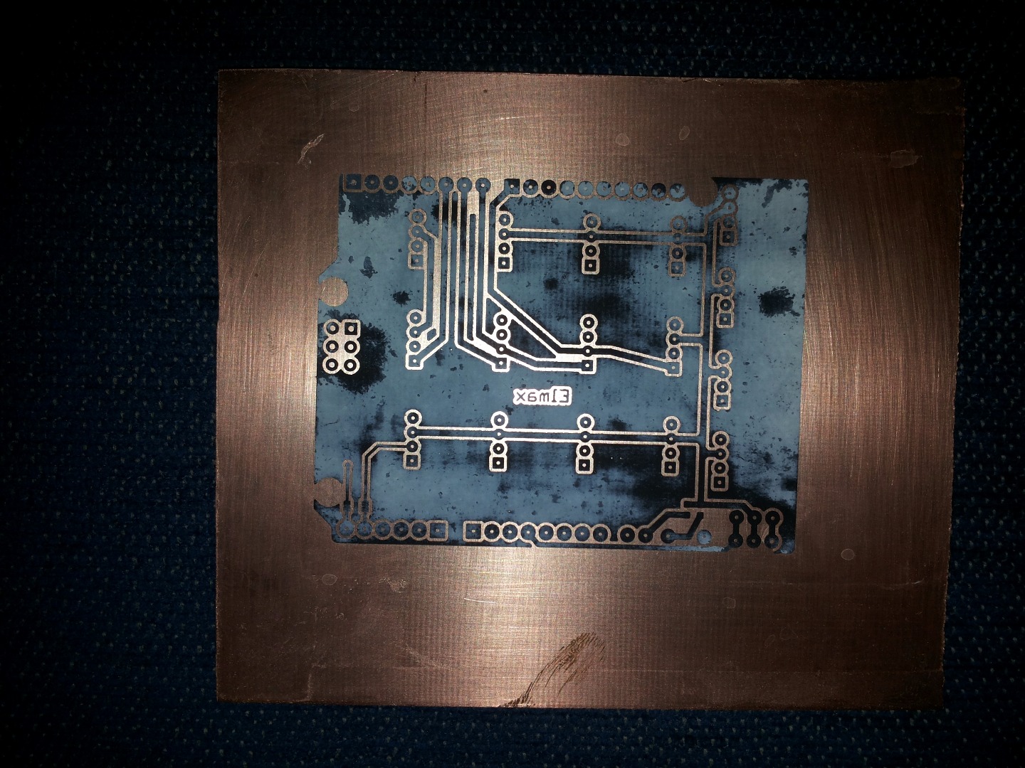
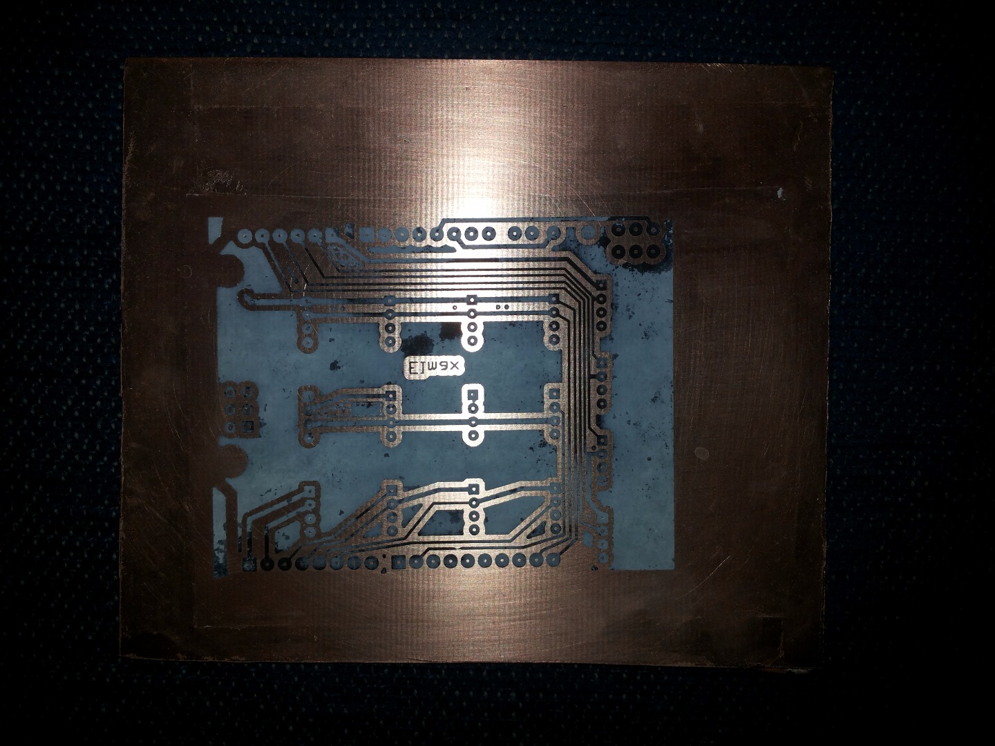
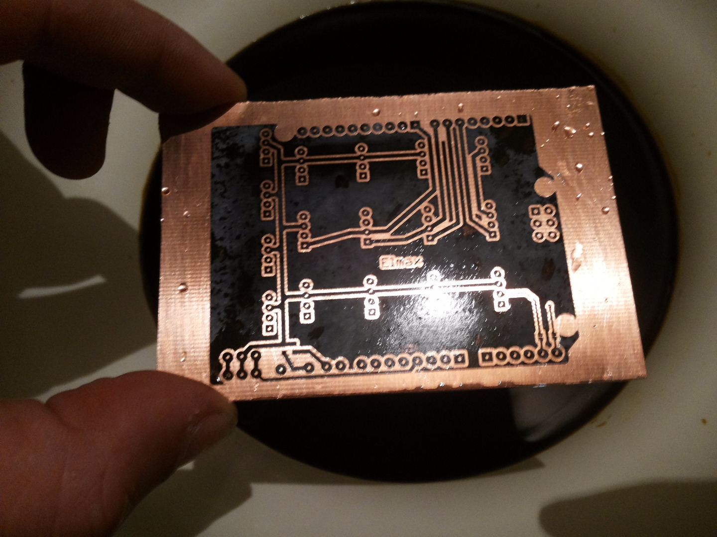
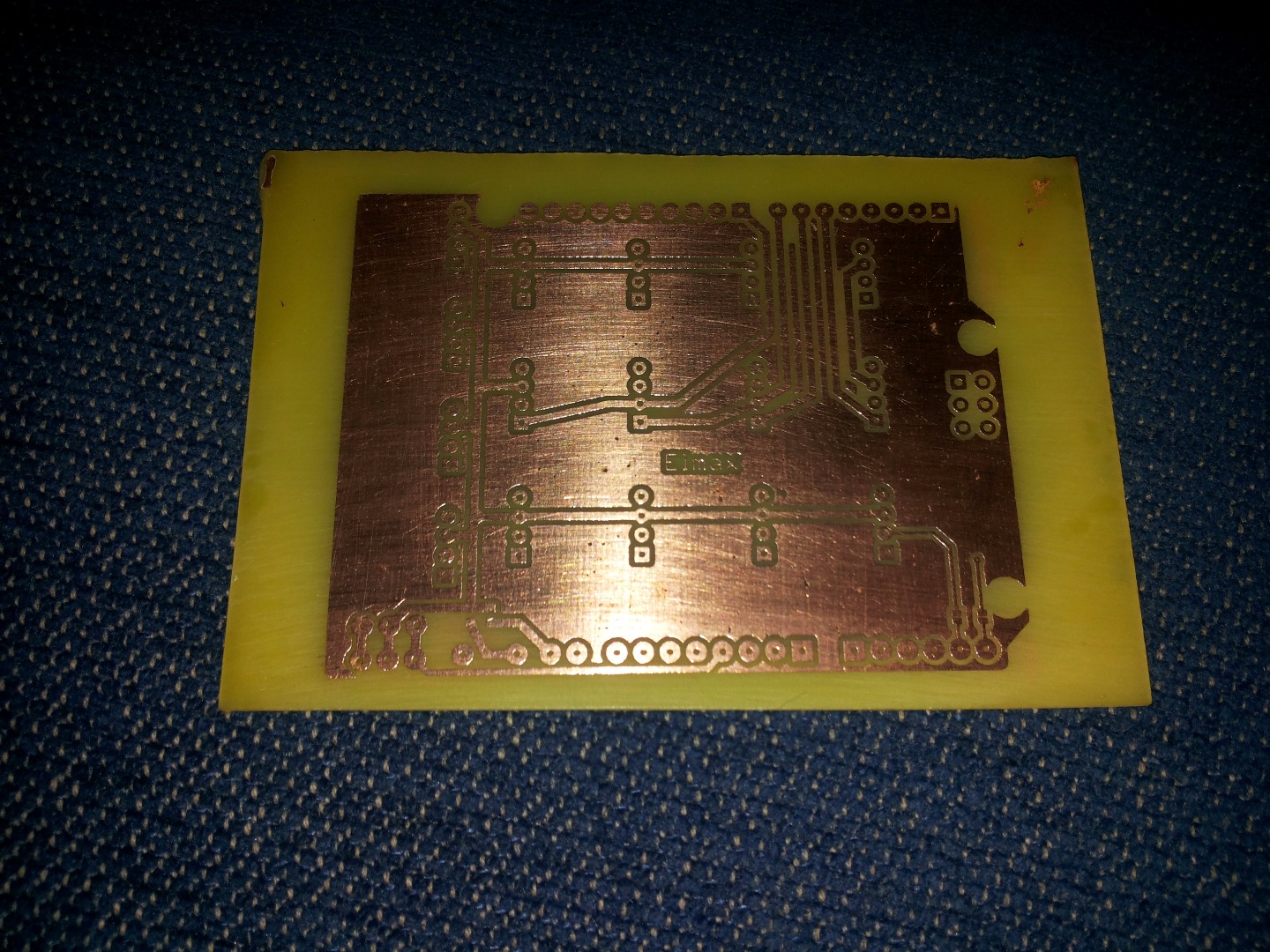
For making custom Intel Edison shield you need next components:
1. PCB board about 100 x 80 mm
2. Cl3Fe Fe-Chloride
3. Laser printed paper
4. Needle or stapler
5. Laminator
Print the mirror side of the top and normal side with the pcb layers. Then use needles to fix the both sides facing towards each other. You can use stapler to fix it or drill the holes on the same spot to secure the paper on the PCB. Take the PCB and insert in the laminator about 10 times changing the side ( I took of the thermistor and set other one to be able to raise the temperature to 190 degrees Celsius. Take the PCB and put it in a bowl of warm water until it is separated from PCB. Then heat the Fe-Chloride on about 40 degrees Celsius and put PCB in them. Move to PCB so the copper can began to be separated from PCB. Remove the remaining toner with the PCB and that's it.
Making Custom Built Relay Module Board and Temperature Sensor
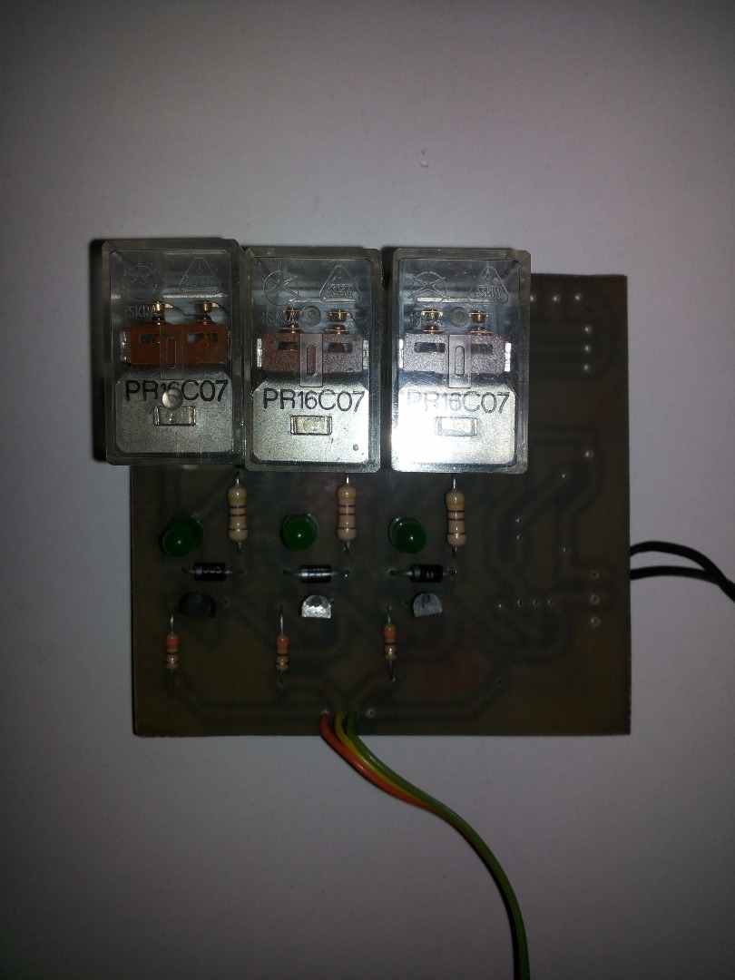
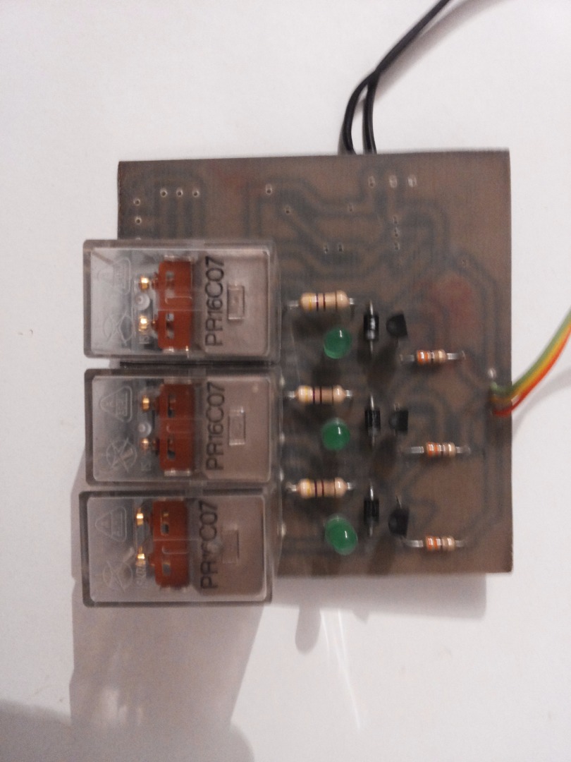
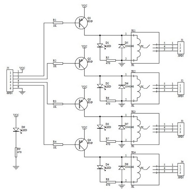
Relay module board - custom builded needs:
1. Printed PCB
2. Relays
3. Resistors
4. Diodes
5. Transistors
5. Optional LED
When I make this relay board I use schematics like from the picture. For transistors I use BC556, diode 1n4005 (that i have home), relays with 12V coil.
Connect these components as you get the picture.
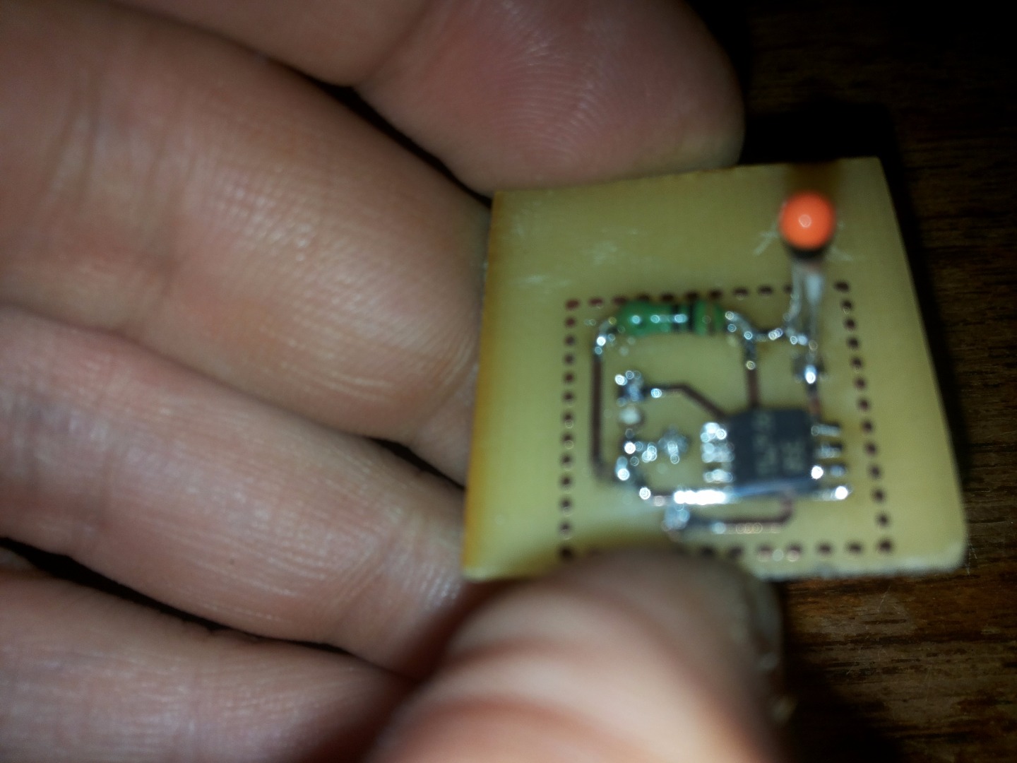
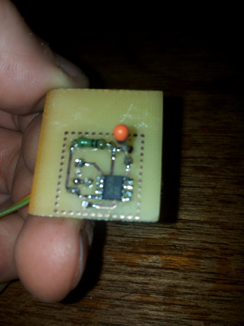
Analog temperature sensor - custom builded needs:
1. Printed PCB
2. IC LM358
3. Thermistor 10K
4. Resistor 10K
When you connecting the components pay attention to which side you facing the LM358 IC.
Testing and Connecting the Sensors
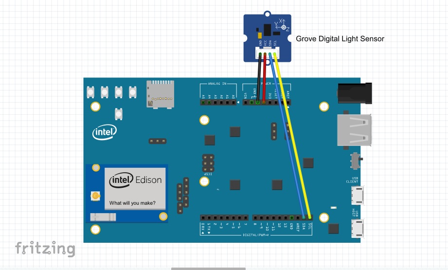
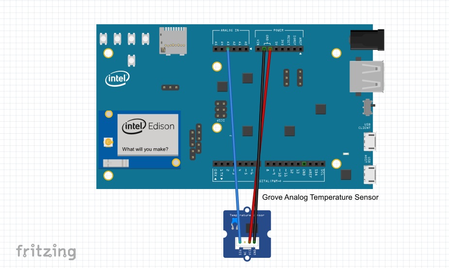
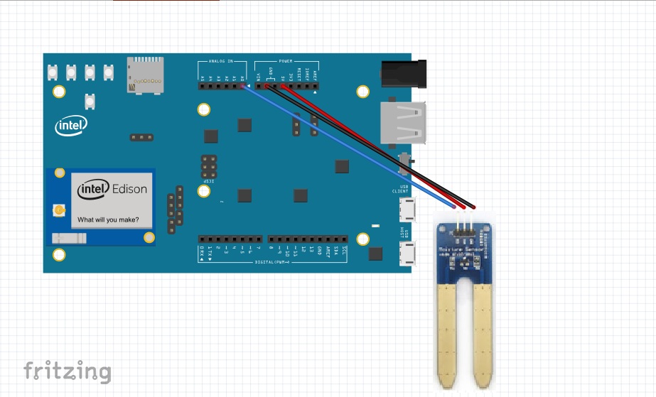
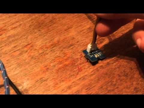
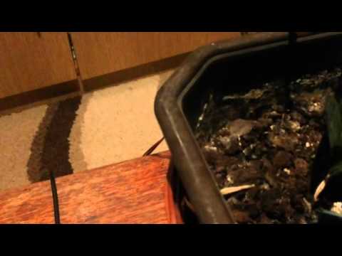

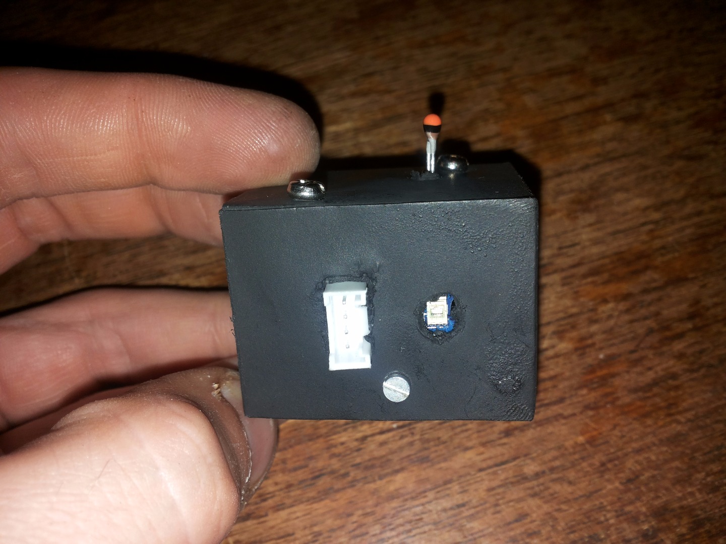
Before the connection of all components in my growbox system i'd like to check out for sure whether all the sensors work and how they should be calibrated.
Before the test started I decided to test each sensor separately, and subsequently to merge them all into one and put it in a cardboard box. It box will be connected humidity sensor, temperature sensor and digital light sensor.
For testing all these sensors I use Arduino IDE. For analog sensors you don't need any special library but for Grove Digital Light Sensor you must use Grove_Digital_Light_Sensor.zip to put it in Arduino libraries folder (for me thats C:\Users\***\Documents\Arduino\libraries\)
Connect sensor like from the pictures above.
Here you can see video where testing Grove Digital Light sensor, Grove Moisture Sensor and custom built Analog Temperature sensor.
Setting Up the System

To get MeLion GrowBox system up and running you need to follow
these steps:
1. Setup the Intel Edison/Arduino Breaking Board*
(for that you need to install and use Putty to configure the Intel Edison Board. You also need to connect Intel Edison on the WiFi. All this steps you can find on this link).
2. Install Blynk application on your smartphone
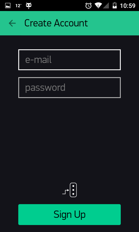
3. Register new account from within the application
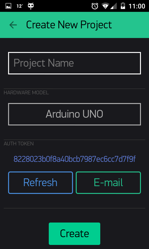
4. Create new project
5. (Optional) email the auth token to your email address
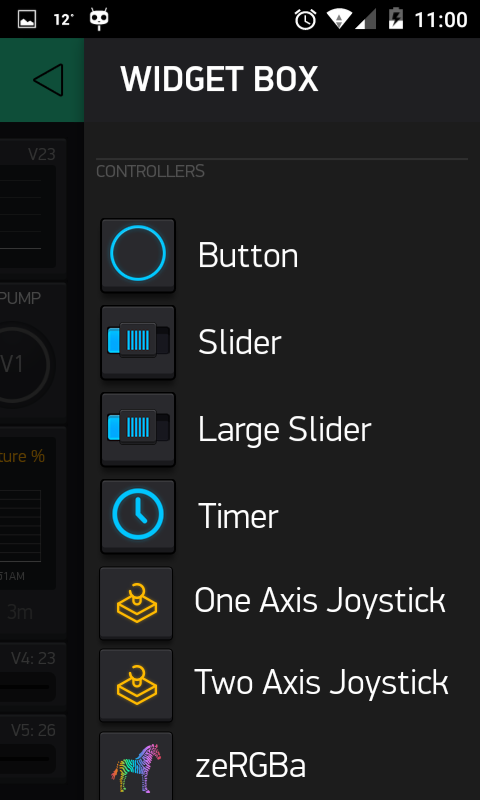
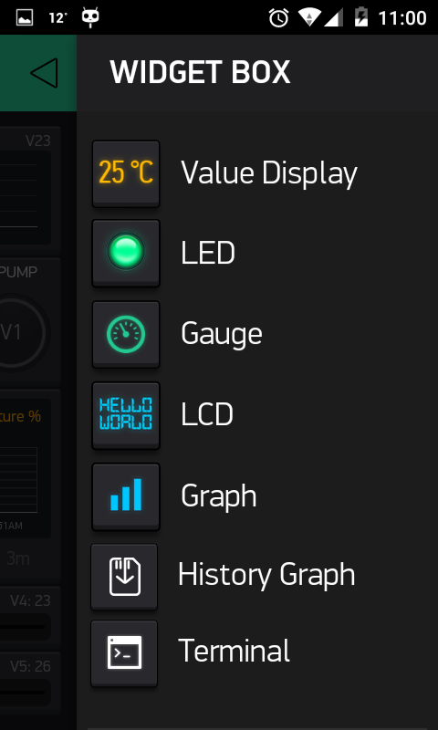
6. Add components/widgets to your Blynk project like described below
7. Download Blynk library and import it into Arduino IDE
8. Download Grove digital light library - Digital_Light_TSL2561 and import into Arduino IDE
9. Download the provided MeLion_GrowBox_v_0_1.ino file and open in Arduino IDE
10. Edit parts of the code where you define Blynk auth token and your WiFi credentials
11. Connect all of the parts to your Intel Edison/Arduino Breaking Board
12. Upload MeLion GrowBox code to your Intel Edison/Arduino Breaking Board using Arduino IDE
(Please note that Grove Digital Light Sensor halts the program if it is disconnected so please make sure it is firmly attached)
13. Using the Blynk app set the parameters as you see fitting
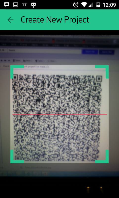
14. Use my QR code so you don't need to setup all widgets in your Blynk app.
Blynk Application Explanation
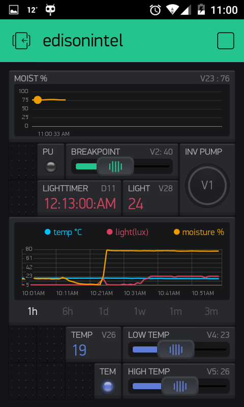
Moisture graph
This graph shows the current moisture value.
Value shown is in percentage, thus its range is 0-100.
Virtual pin #23 is used to send moisture value from board to Blynk app.
Pump LED
This led turns on when pump is turned on (irrigation is in progress).
Virtual pin #25 is used to send signal to Blynk when pump is on.
Breakpoint (for moisture)
This slider widget is used to set the value of soil moisture percentage that is used to turn on the irrigation pump. When moisture value drops below this value pump is turned on and when value is raised over the value pump is turned off.
Since it takes some time for the moisture of soil around the sensor to absorb the water coming from the irrigation system, value will actually keep rising a little longer after the pump is turned on, thus prolonging the time needed for moisture value to drop below the breakpoint again.
Virtual pin #2 is used to get moisture value.
Inv (Invertor) Pump
This button inverts the current state of pump.
So, if the pump is currently running and you press the button, the pump will stop.
Likewise, if the pump is currently not running and you press the button, the pump will start running.
This is handy if you want to manually turn on irrigation or if you want to access your plant but the irrigation is getting in the way.
Virtual pin #1 is used to send this operation signal to the board.
Lighttimer
This timer widget is used to set when the lights in the growbox are turned on and off.
This allows you to simulate different day/night periods for the plants.
You simply set the desired time period and application turns output of digital pin #4 to either HIGH or LOW.
Light
This display widget shows the current light level inside the growbox.
Virtual pin #28 is used to get this value.
History Graph Widget
This widget is used to display values of temperature, moisture and light over a period of time.
Your can change the period displayed using options on the widget.
Temp (value display widget)
This widget shows the current temperature value in degrees Celsius.
Virtual pin #26.
Temp LED
This LED shows if heating is currently turned on or off.
Virtual pin #24.
Low temp and High temp
These two sliders are used to set breakpoints for heating.
Since heating that I use has less “inertia” than irrigation system I use two breakpoints here.
When temperature drops below the low breakpoint heating is turned on.
Heating keeps running until the high breakpoint is reached.
Virtual pins #4 and #5 are used here.
Analog pins
A0 - connected to Moisture sensor
A3 - connected to Analog temperature sensor
Digital pins
D2 - connected on relay module for Heater
D3 - connected on relay module for Water pump
D4 - connected on relay module for LED strips light
Connecting MeLion Growbox System
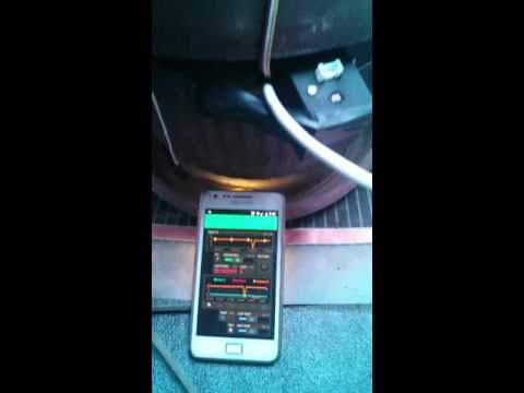
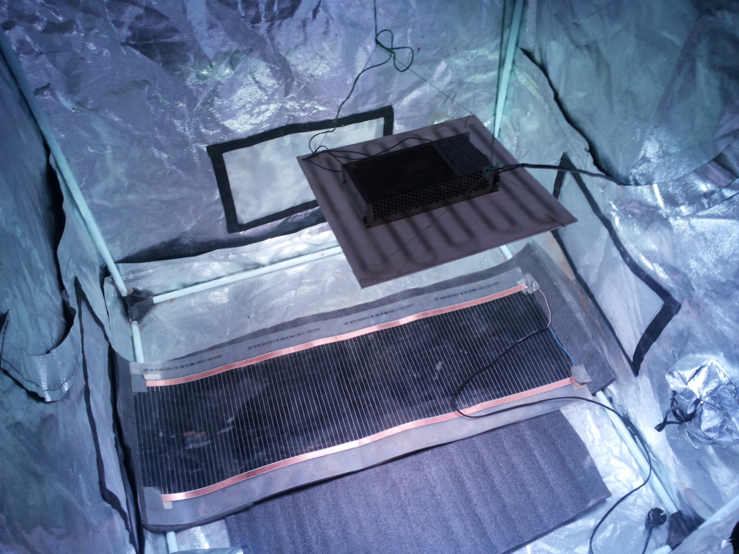
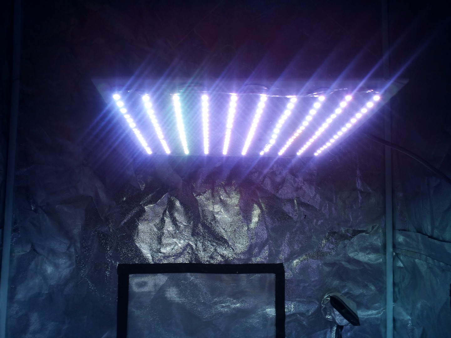
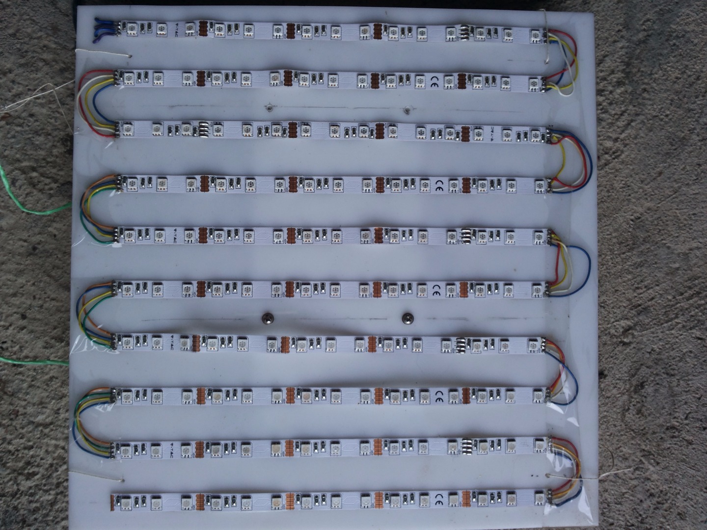
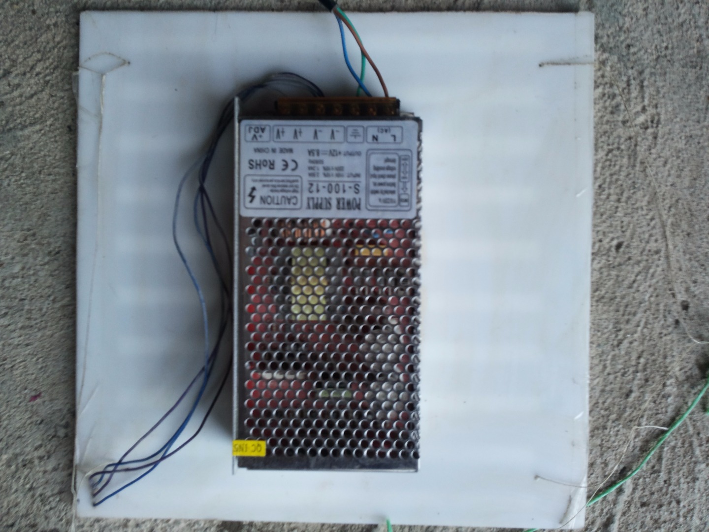
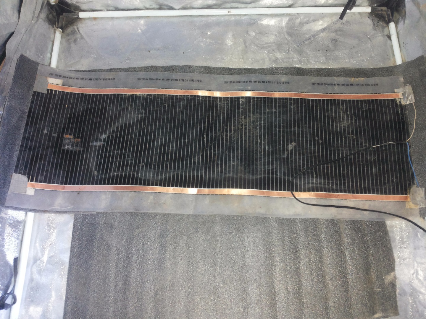
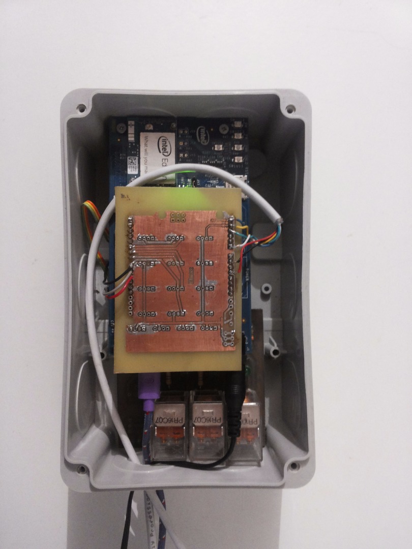
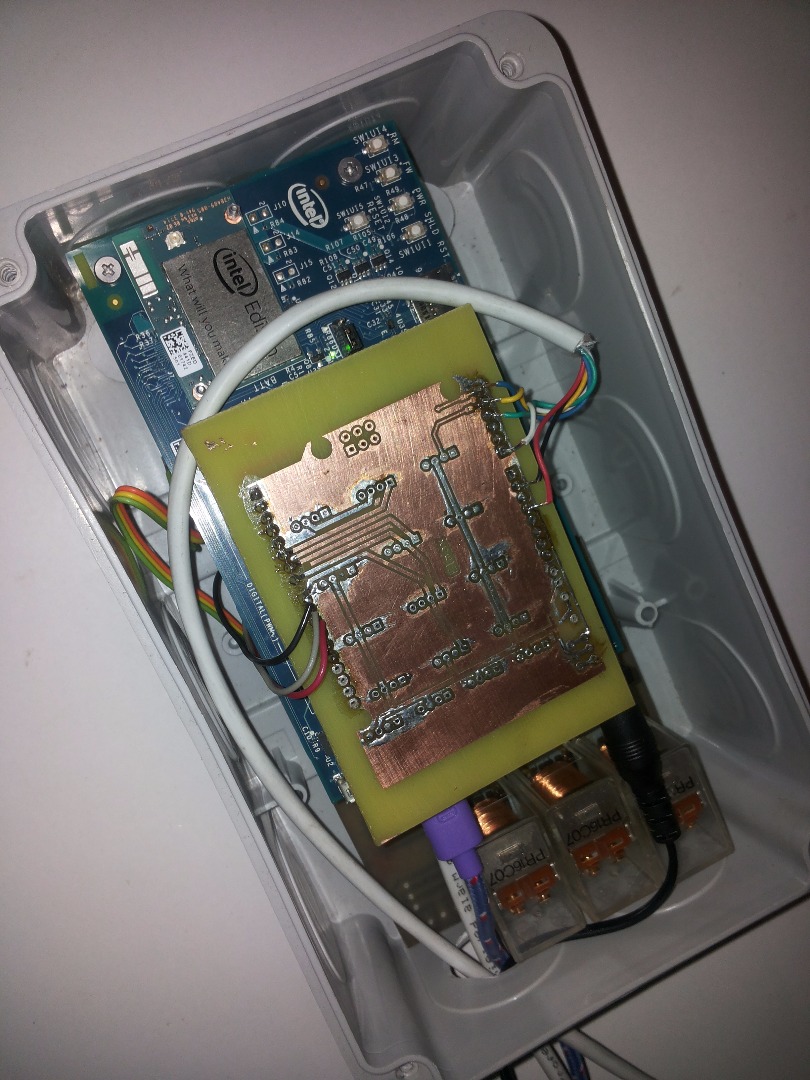
First of all you must connect:
1. LED strips on plastic plates connect on power and on relay module
2. Flat Heater on relay module.
3. Mini water pump on relay module
4. Sensors for temperature, moisture and light
5. Setup Intel Edison Arduno Breaking board with relay module and shield.
6. Start up Blynk app
7. Enjoy watching your plant grow :)
Conclusion
As you have seen, it is relatively easy to assemble MeLion.
GrowBox system and get it up and running.
It can help you grow your plants more easily and provide them with optimal growth conditions.
The system can and will be further improved, so all of your feedback is more than welcome.
My idea was to bring agriculture closer to ordinary people. I hope this system will help at least some of them and inspire them to further develop the system and share their experiences and ideas.
I hope you like my instructables so please VOTE for me for Intel Invitational contest.
Thanks :)