Max MSP Ambient Loop Generator
by MotorCityHammer in Circuits > Audio
2131 Views, 5 Favorites, 0 Comments
Max MSP Ambient Loop Generator
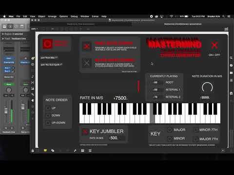
This is a tutorial on how to get started making an ambient loop generator in Max MSP.
This tutorial expects that you have a basic understanding of Max MSP, DAW interfaces, and signal processing. If you want to use the program designed in this tutorial, go ahead and download it, free to use (but not to sell or re-publish)!
The program that we'll be designing has TWO main portions:
1) A multi-signal processor
2) A semi-randomized note generator
The note generator runs slowly along a key/scale in semi-random patterns, feeding MIDI data into a DAW, which in turn sends audio back into Max to be processed.
Here is a link to the final patch file: https://drive.google.com/open?id=1XIkIAbqlHvIiCmelkIV2kY4P6CGvKEBM
Supplies
- Basic Max MSP and MIDI knowledge
- Max MSP
- Audio Interface (we're using Logic Pro X)
- Soundflower
- (Optional) Some good software instrument plugins for your DAW
Setting Up Soundflower With Max and Your DAW
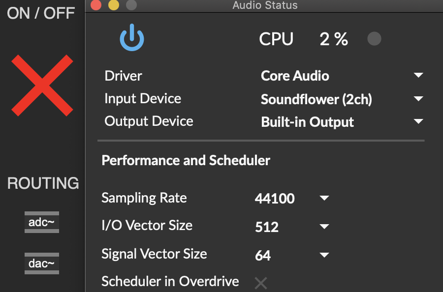
Soundflower is a program which helps to send audio between programs on Mac. We'll be using this to get audio from our DAW into Max.
Using Soundflower with your DAW couldn't be any easier! Simply download Soundflower, and it will become available to use as an audio output and input. If we create an adc~ (audio input) and dac~ (audio output) objects, we can see that Soundflower 2ch and Soundflower 64ch become usable audio pathways. We'll be using Soundflower 2ch (2 channel) for this program.
In Max, add a toggle to turn your input on and off, and a gain slider for volume, and you'll be on your way.
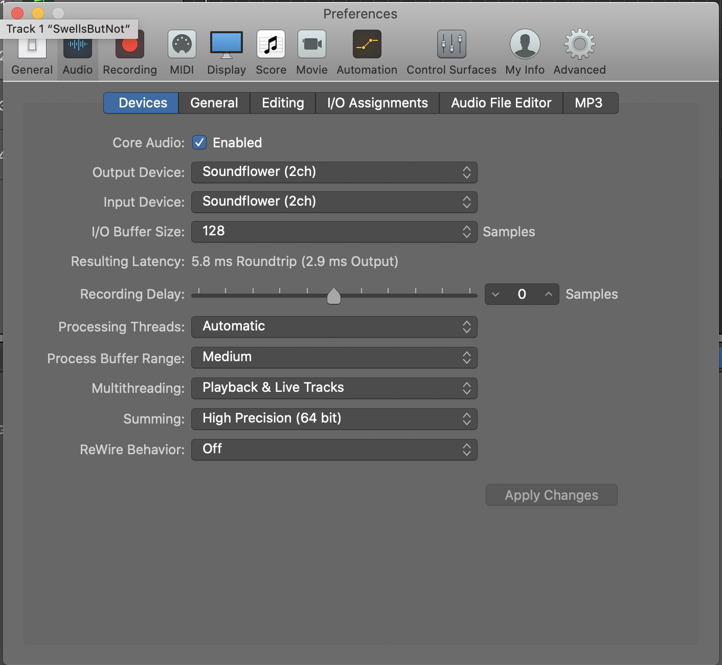
In your DAW, under preferences > audio you will see audio input and audio output. We'll be using Soundflower 2ch as audio output.
Decide Your Signal Processing Path.

In simple terms, will your audio be distorted in a bunch of different channels, or all in one straight line?
We decided to use parallel audio processing - our signal will be distorted on multiple different channels. This gives us the benefit of clearer overall audio and more control for our signal, but pushes a lot of volume into the master gain, resulting in some clipping. We decided that more control was worth some distorted audio, since this will create ambient loops anyway!
Additionally, you'll need to decide what effects you'd like to create. We'll be demonstrating some effect types here if you want ideas.
Adding a Dry Mix.
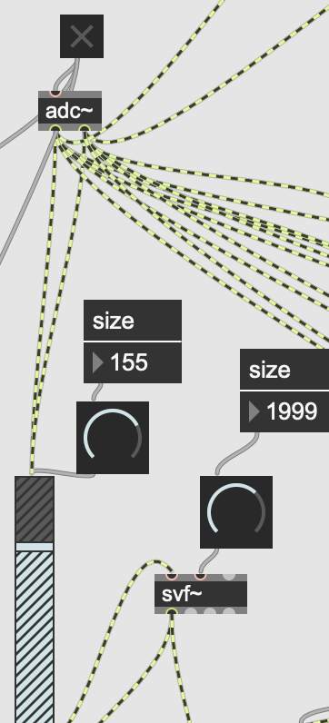

We first added a "dry mix" so that we could have a separate, unaffected audio signal. This was done by running the adc~ output into a gain slider (with a dial to make it easy to view), into an svf~ filter with a dial to adjust lowpass filtering, and then into master gain and out to the dac~. Having a dry mix can be pretty handy, so we suggest it if you wanna keep things somewhat clear sounding and easy to test!
We might've caught your eye a bit there - we'll be running all of our effects into separate svf~ filters to have tone dials for each signal channel. This makes it easy to clear up the audio space when a particular effect is too high frequency. We made all of our svf~ lowpass filters (by hooking up to the lowpass output), so they progressively cut off high frequencies by turning down the dial. However, svf~ also has bandpass (selective frequency), highpass (remove lows), and other useful filters. Experiment to see what you like and need, or even use multiple filters!
Shifting Pitch With a Pitchshifter.
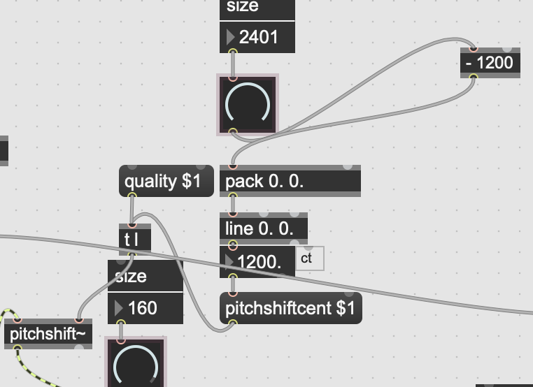

For a simple, easy to use pitchshifter, copy the pitchshifter code from the pitchshifter help guide in Max. Our code is very similar, but removes features like glide and multiple audio quality settings to cut down on clutter. Running your audio into this (from adc~ for parallel sound, or from the dry mix for series sound) allows you to use a dial to adjust the level of pitch shifting.
As with the dry mix, we added a gain slider and an svf~ object to allow for volume control and EQ shaping.
DISTORTION!
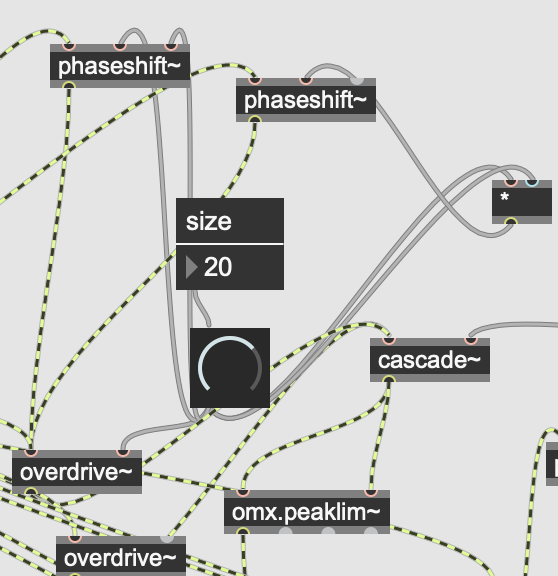

Using the overdrive~ object is the simplest way to add distortion. You can run that into a gain slider and a filter and call it a day. However, we took it a couple steps further. Firstly, we ran the left and right audio paths into separate phaseshift~ objects - these place the left and right audio paths out of phase, "thickening" the audio like how a chorus pedal might.
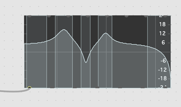
Additionally, we sent the resulting audio into a cascade~ object with a filtergraph attached. This allows you to distort the audio more or less in certain frequencies, and with as many filter bands as you'd like. Our distortion filtergraph was modeled after the distortion of a 1980's Boss HM-2 Heavy Metal pedal.
At this point, we also began adding omx.peaklim~ objects after especially noisy effects - this object limits the audio signal coming through it like a compressor would, making it easier to keep the final audio path from clipping.
The Power of Drone.
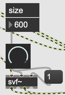

We also felt it necessary to add a "droning" frequency to our patch. While this could have been accomplished with a cycle object to create a simple oscillator, it wouldn't have been very adaptive to volume or frequency changes in the original audio. Therefore, we used an svf~ filter to create an ultra resonant audio path. By running audio into an svf~ filter, and setting resonance to 1, we create a droning frequency that moves in and out as our audio path does, and can then be adjusted for loudness, tone, and frequency. Adjusting the attached dial will adjust the droning frequency.
Entering the Bizarre: Ring Modulation.
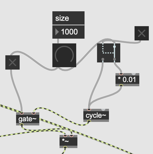

Now, we move on by adding ring modulation! This fun and cool effect is extremely simple to make, and very misunderstood because it sounds... a little funky. This is accomplished by attaching a dial to a *~ object in the right inlet, and in the left inlet attaching our dial. We took this a step further - when our ring modulator is all the way down, a gate closes off its number signal, and so the ring mod signal is totally cut off. Additionally, it can also be toggled to output to another * object which reduces the frequency by a specified amount. This way, we can have a "fine", tremolo-type ring mod, and a faster, weird sounding ring modulation. Like the other effects, this was run into a gain slider and an svf~ filter.
Delay and Signal Degrading... Degrad... Deg... D.....
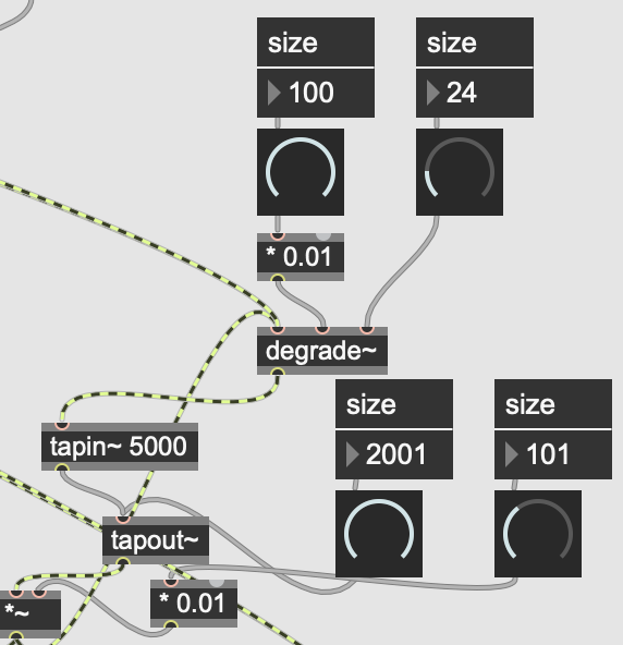
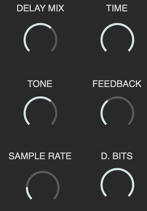
Here we are creating a delay with time control, a feedback dial, a tone dial, and sample degrading. This allows us to mimic an analog delay by progressively making the signal quieter and more distorted. To do this, we use connected tapin~ and tapout~ objects. We write 5000 after tapin~ to make sure it has 5000ms of memory time. Adding a degrade~ object lets us progressively destroy the signal. Then, we run audio from adc~ to our degrade~ object, into tapin~, into tapout~, and simultaneously back into degrade~ from a *~ and out of *~ to our gain control. Doing this allows us to attach a dial to adjust the volume of delay going back into itself and to have a delayed signal coming from the *~ object to our outputs. Additionally, placing the degrade object before tapin~ allows us to add more and more and more sample reduction as the signal is delayed. Check our picture and code for a clear view of how this was all done.
Belton Brick Style Reverb.
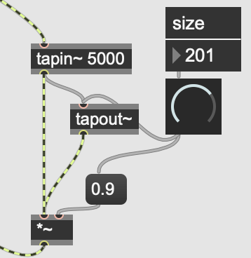

A belton brick reverb refers to a reverb equipped with an Accu-Bell BTDR Digi-log chip designed by Brian Neunaber of Neunaber Effects. This chip allows for simple spring reverbs using cascading delay lines. To emulate this, we've coded another delay, with one dial to adjust the time and feedback. The time will never cross 100ms, and the feedback is capped at 80%. This simple delay gives an easy spring reverb sound! Out into a gain and tone control once more.
Random Stereo Tremolo.
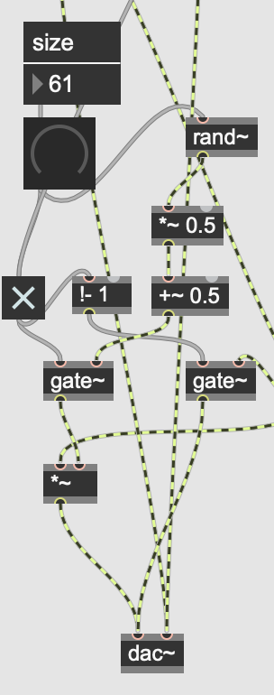

Our final signal effect! Here we've created the same code used before for the ring modulator, with a couple twists: the depth of the tremolo is randomized, and there is a tremolo for the left and right channel. Additionally, we set this unit up in series, so that all effects now come before it, so every signal is effected by the tremolos.
To do this, we mimic the ring mod code from earlier, with some changes: the signal now runs into two gates which open when the other is closed. This allows the signal to be either affected or unnafected, rather than affected or off only. This was done with the !- object. Our dial runs into a rand~ object, then *~ and a +~, and down to another *~ in the right inlet and the audio in the left. Here we have a randomized tremolo that turns on when the dial is up, and down when it's off!
This does not need a gain control or tone control, so it just goes straight to the dac~ object.
Oscilloscoping!
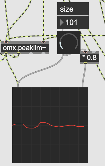
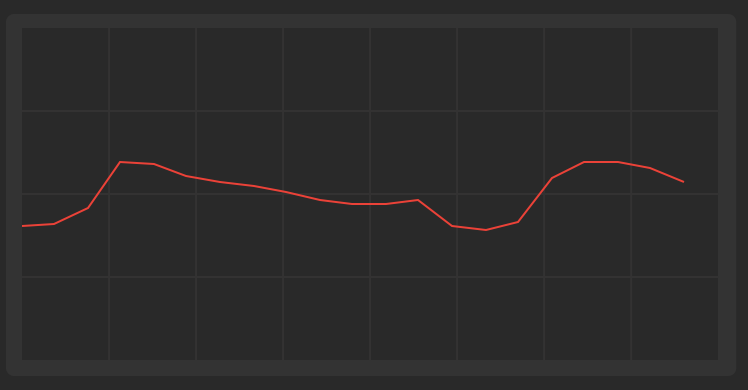
Lastly, we add a scope~ object connected to the audio output from the master gain control. We also added a dial to adjust its sensitivity!
Presenting the Signal Processing Module.
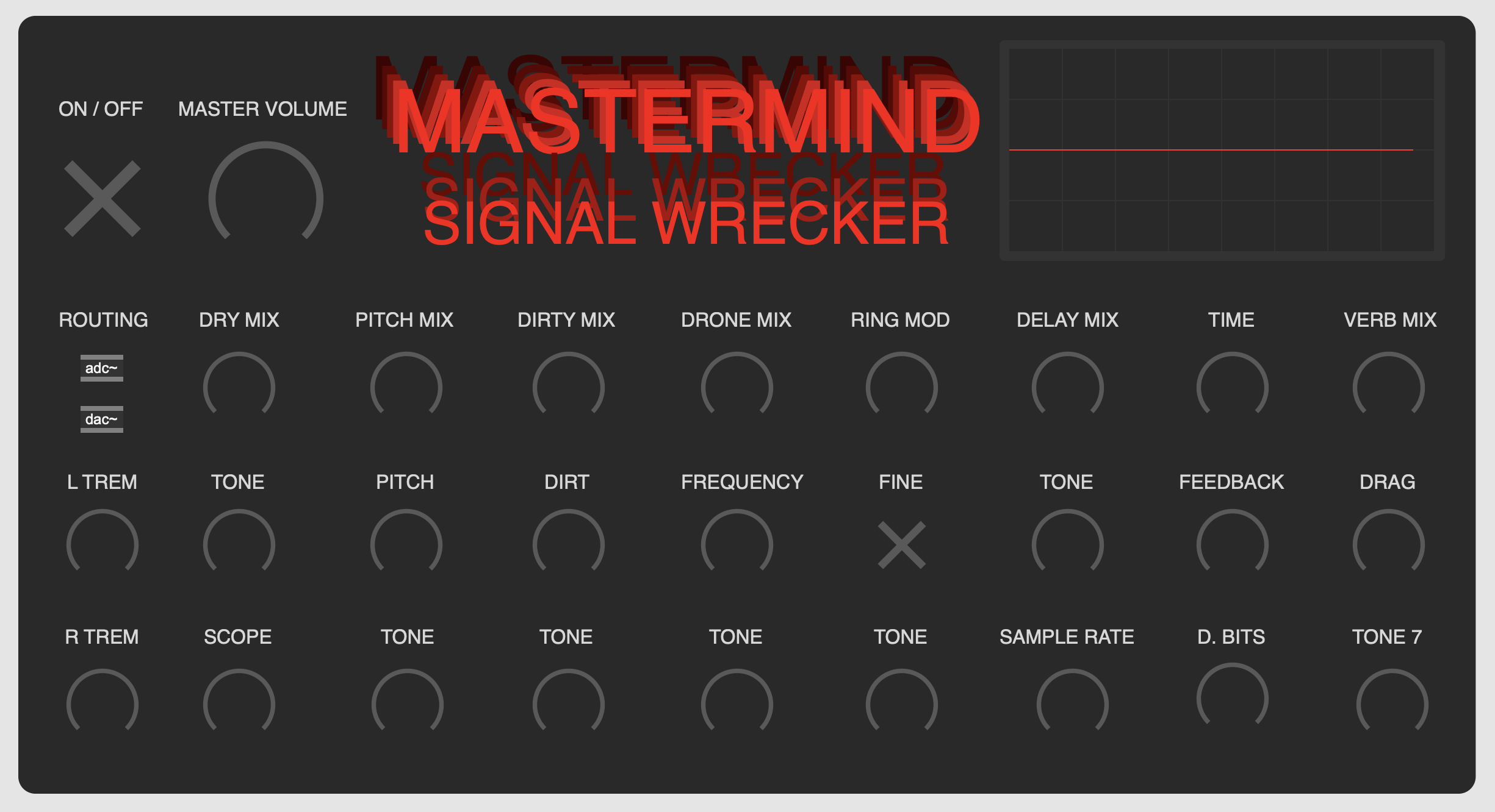
We finish off this section by giving our code some flair in the presentation mode. Just add individual dials and comment boxes to the presentation mode, and you'll be good to go! We gave ours some extra flair with colored boxes and various font and artsy design decisions. Additionally, the design was based off of guitar pedal designs: dials in labeled rows and sections to make the signal path simple to understand. Have fun with this part!
Section 2: the Chord Generator
We now have a fully functioning signal processor in Max, we just need some audio to feed in to it. By using Soundflower, we can route all the sound being outputted through the signal processor, so long as the source is your computer!
In order to create our own ambient loops however, we will have to make another Max patch. Thanks to the power of MIDI, the finished patch will effectively serve as a novel MIDI controller for your DAW, sending notes directly to it allowing you to use any instrument of your choosing or design! As opposed to an external MIDI controller, with the power of max we can create a MIDI controller that can play all by itself, allowing you to modulate it with the signal processor with ease.
For unique note generation, we will be using an arpeggiator to generate triads, and later on we will look at how to put together an algorithm that will allow the arpeggiator to jump between chords.
Getting Notes to Feed Into the Arpeggiator
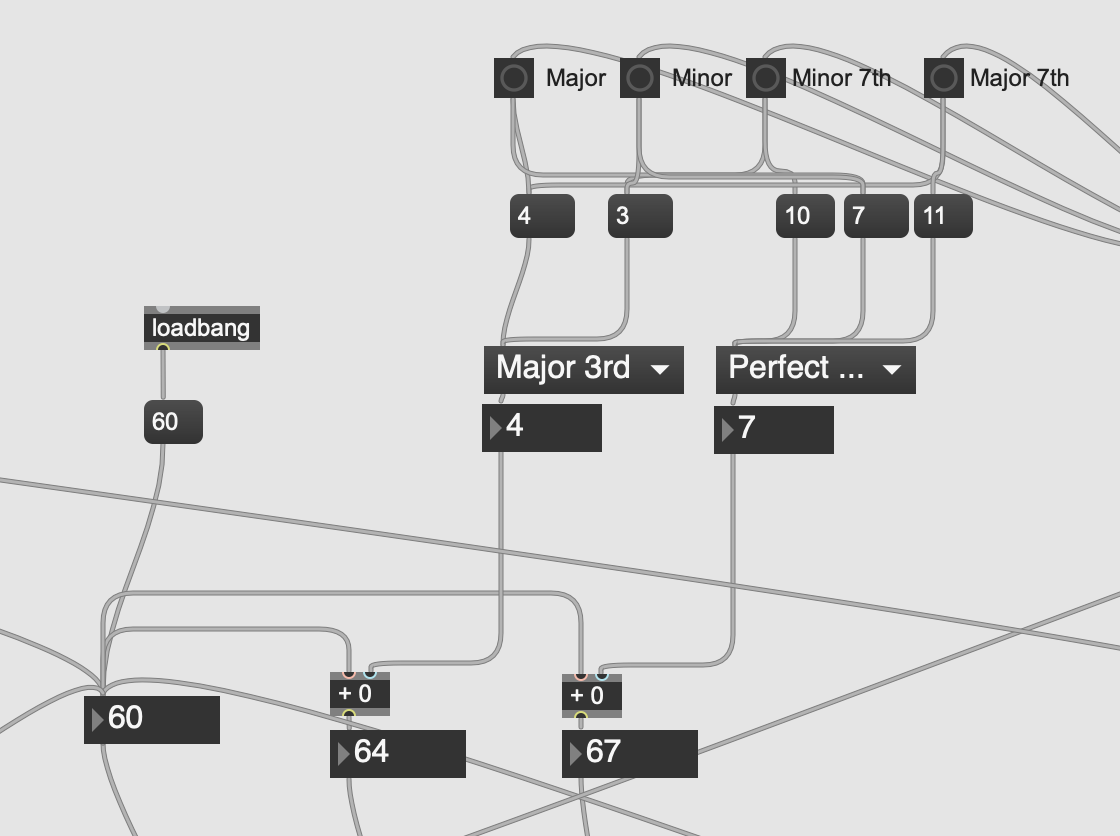
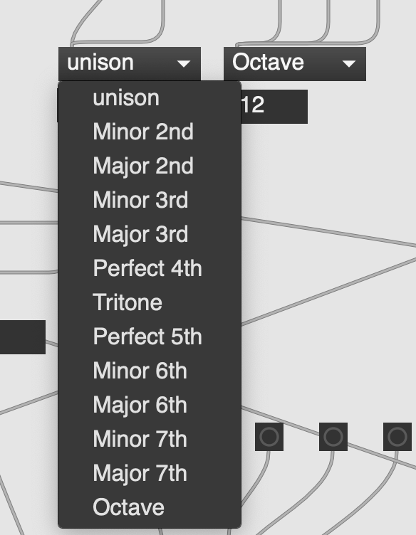
Before we can put an arpeggiator together, we need to be able to generate the chords for it to sequence through. In MIDI, every note on the keyboard corresponds to a number, with middle C being 60. Fortunately, the numbers are sequential, so by applying some music theory, we can generate the correct intervals that correspond to various key signatures.
The key signatures you use are up to you, however you can also follow along with the 4 key signatures we selected. Later on we will add to this part of the code to allow it to cycle through the key signatures on its own, so we selected Major, Minor, Major 7ths, and Minor 7ths to help preserve tonality as the program cycles through chords.
Referring to the first picture, the bulk of this section is just the math that corresponds to the intervals of these keys. Starting with the leftmost box labelled '60', thats the root. Whenever the root changes, the intervals will change correspondingly based on the current key. For example, if the major key is selected, the corresponding intervals are 4 and 7. That then run through the +0 boxes, which will add that interval to the root, and provide you with the 3 notes to make a major chord, from any root!
Arpeggiating Those Chords
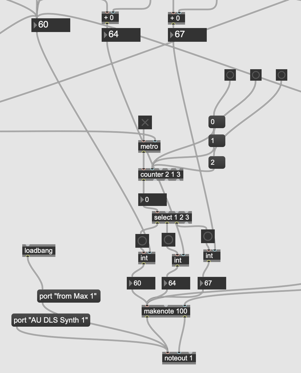
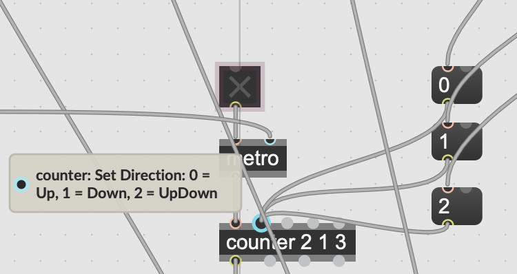
Refer to the photo above for the code for the Arpeggiator. The counter object and the attached 0, 1, and 2 object boxes are going to allow you to control the direction of the arpeggiator from Up, Down, and UpDown.
As shown above, the interval generator that we just put together is being routed to the 'int' boxes, so as the counter and select boxes run, it will be going through the chord from the other chunk of code. This then runs through the 'makenote' and 'noteout' box to finally turn these MIDI numbers into sound!
Take note of the of the 'port "from Max 1"' object thats connected to the 'noteout' box, as this is what allows you to send the MIDI information from Max into your DAW.
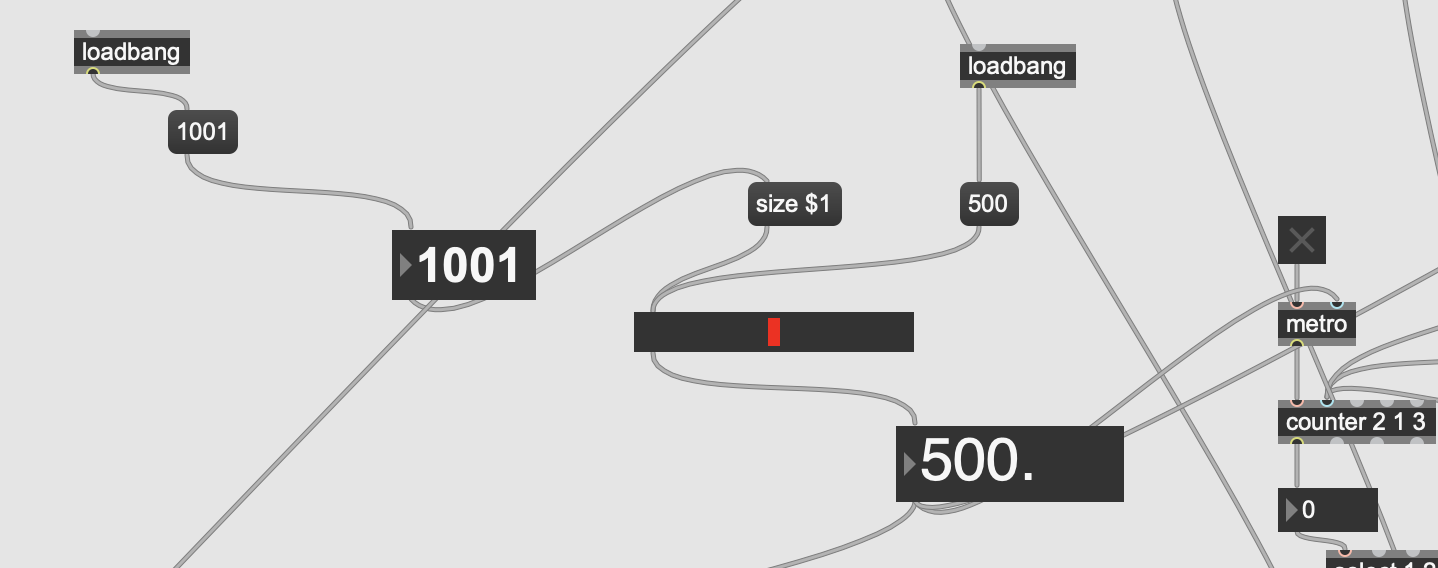
The 'metro' object determines how much time is between each interval in milliseconds. I have it default to 500ms, and if you follow the attached code, using the slider object you can adjust how many milliseconds are between each interval
The 'Key Jumbler'
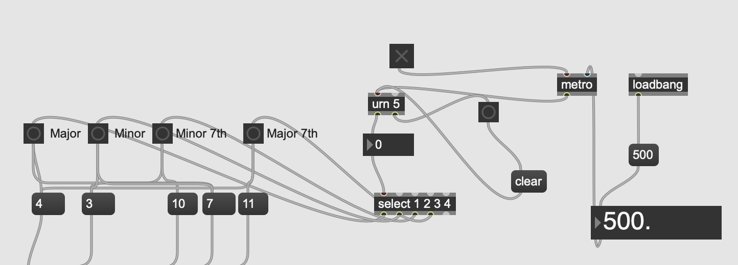
Pictured above is the piece of code that will allow the program to automatically cycle through the key signatures, allowing you to create spontaneous chords as you select different root notes.
The 'select' object is functioning very similarly as the one in the arpeggiator section, however instead of a specific sequence, we are using the 'urn' box to randomly cycle through the keys. What makes the 'urn' box different from 'random' is that it will not repeat a number until it has gone through the whole range, which in turn provides us with an even distribution of jumps between different the different keys.
Making the Magic Happen With Autonomous Note Generation
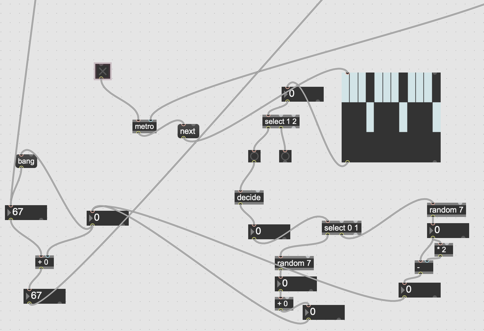
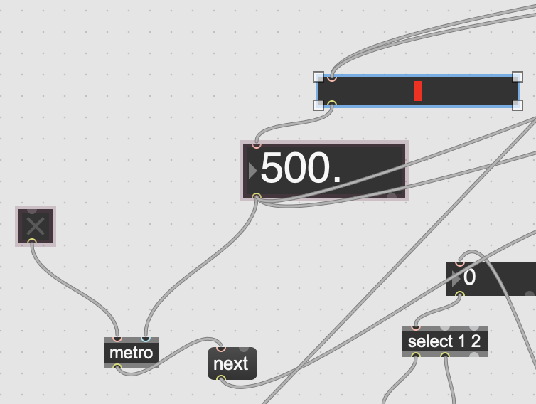
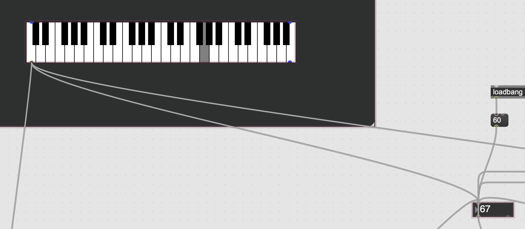
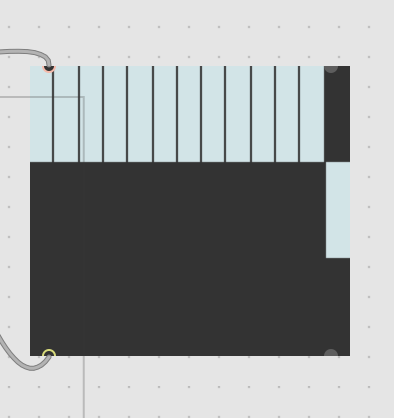
This chunk of code is what brings this patch to being able to run autonomously. If we refer back to the chord generator from the beginning of this section, changing the root will automatically fill in the following intervals, so we can use that to generate unique chord progressions!
The key item here is the 'itable', or the large square with the small blue rectangles inside. By attaching this to metro parameter from the arpeggiator (the box set to 500), we can control the exact point in the arpeggiator sequence that the chord changes. Since the Arpeggiator runs in sets of 3, the size of the itable is set to 12, to account for 4 cycles, and the range is set to 2, with 2 serving as 'no' and 1 serving as 'yes' for whether or not to change the chord. With the sequence in the main code, the arpeggiator would one through one triad, then a new chord would be generated and it would run through that triad, and so on.
The 'random' boxes determine how far the new root is from the original, currently I have it configured so that it can go up to half an octave up or down.
In the full picture of the code, seen off to the left the 67 number box on the bottom is attached to root number box from the chord generator, so whatever number ends up being generated from the itable and its attached algorithm will go to the chord generator, and then into the arpeggiator where it will play the newly selected chord. The 67 number box above it thats running into the '+0' box is attached to the piano object pictured above, which is also attached to the root number box from the chord generator. This is so that when the algorithm from this chunk of code generates a number, it also gets selected on the piano so it will trigger that note to play.
In the final code, this section appears twice, with the only difference being the itable. Refer to the separately attached itable for how to make it so that a new chord is generated after the arpeggiator repeats a sequence 4 times.
Finishing Touches
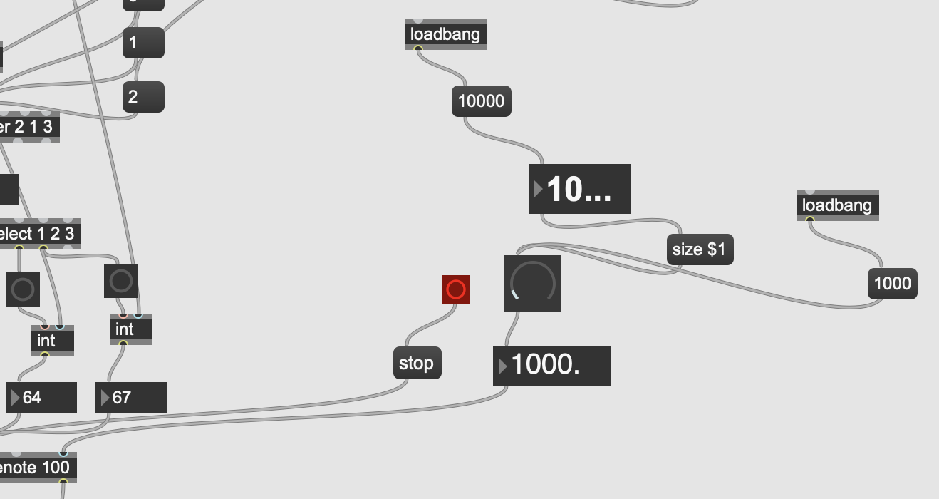
You should now have a fully working self playing arpeggiator! However, if you want to add a bit more control, the piece of code pictured above will allow you control the duration of the notes being played, so you can get long drawn out notes perfect for a slow, droning, ambient loop.
Also attached is a 'stop' object, which is particularly helpful when you are running Max through a DAW. In a case where Max starts having issues communicating the MIDI data, you can override it and stop it without completely closing down Max or your DAW.
Wrapping It All Up
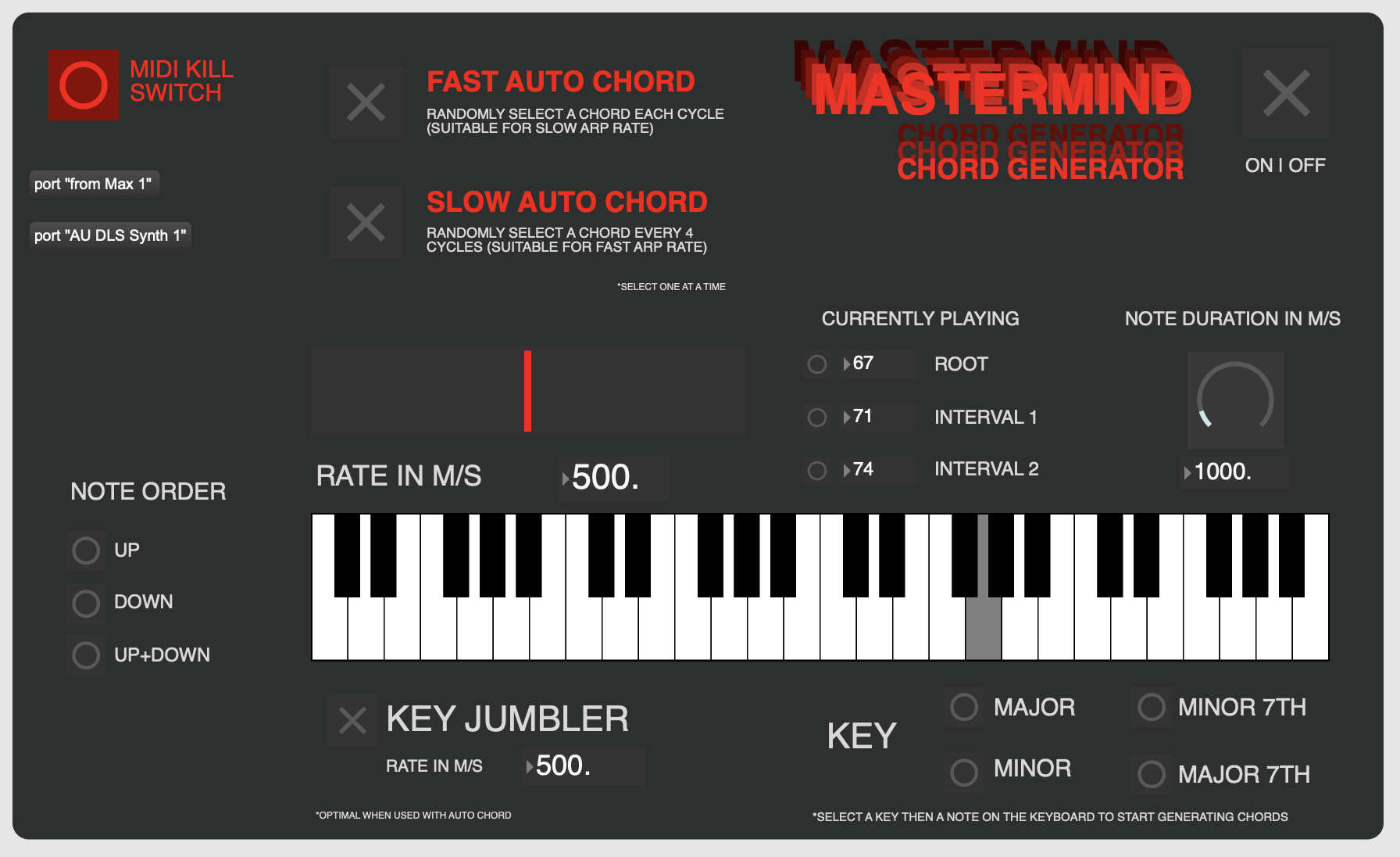
The program is now functionally complete, all thats left to do is organize everything into presentation mode. There isn't one end all be all solution to this, its entirely dependent on what you want to be able to control from a surface level.
My selection covers the essentials of everything I want to be able to easily modulate, so you can add to it or take away from it as you see fit.
All that's left to do now is to get familiar with these two patches, and start creating some music!
Enjoy!