Materializer: Interactive Drawing Interface for Digital Fabrication
by merttoka in Workshop > 3D Printing
885 Views, 10 Favorites, 0 Comments
Materializer: Interactive Drawing Interface for Digital Fabrication
Developed as the final project of MAT 594X - Computational Fabrication, shelter-in-place edition (Spring 2020), by Jennifer Jacobs.
Materializer is an interactive drawing system for 3D printing with direct user input. Its drawing interface allows users to sketch freely on 2D surfaces that stack on top of each other and create a 2.5D canvas. It features two fabrication modes: (1) send print instructions whenever a stroke is completed, and (2) batch-print only the 'selected' strokes.
The first mode is useful for getting familiar with the system. Sketching is an expressive and rapid interaction that offers a gentle slope system to the user. I wanted to retain this notion as much as possible by providing a quick response to the user input, and printing the stroke whenever it is finished. The user discovers the affordances and limitations of the system with this mode (How accurate are the lines? Can I control the precision parameters? How's the print quality? etc.). And, the second mode is a more pragmatic take on the sketching idea. In this mode, we can sketch freely, 'select' multiple strokes and send them to the printer as a batch job. This allows us to continue working on other parts of the sketch while a set of strokes is being printed. This mode will sort the strokes in ascending-Z order before starting the print.
This system could contribute to the field of HCI by
- motivating and enabling novices to learn more about CAM pipelines, and empowering experts by freely sketching on a 2.5D canvas to fabricate prototypes
- creating new affordances by breaking out of the fabrication pipeline: multi-material prints with Ender 3 Pro, non-linear GCode scheduling on arbitrary layers, etc. (see Step 3)
- releasing two open-source software:
- The back-end is a general-purpose controller for 3D-printer hot-ends implemented in Python. It listens to some OSC commands to author nozzle movement. This implies a 3D printer can also be used remotely.
- The front-end is implemented in Processing. It handles the virtual representation of the printer hardware along with a multi-layered canvas interface and basic interface level features (nothing is extensively tested yet).
Supplies
Inspiration and Background
.jpg)
.jpg)
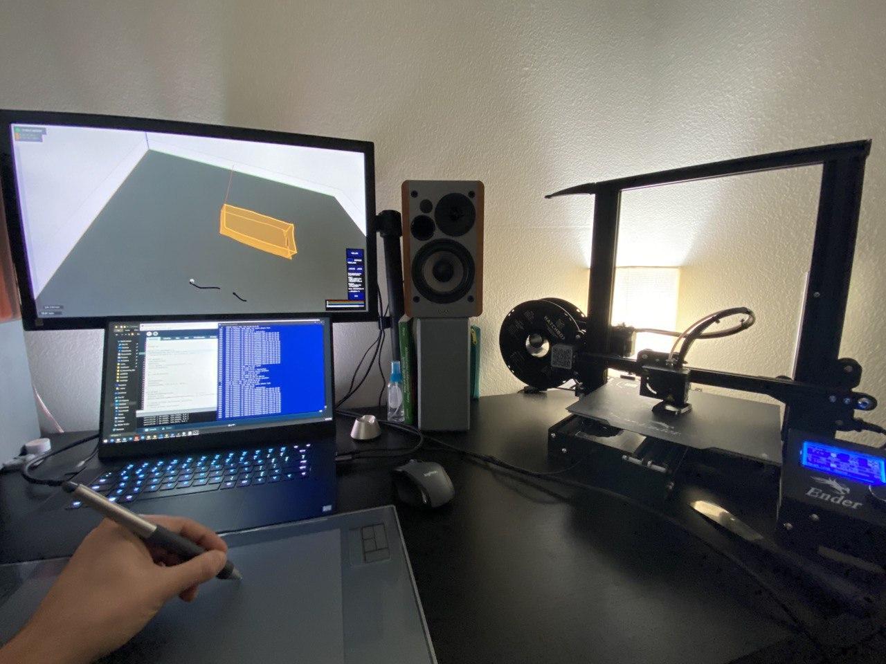
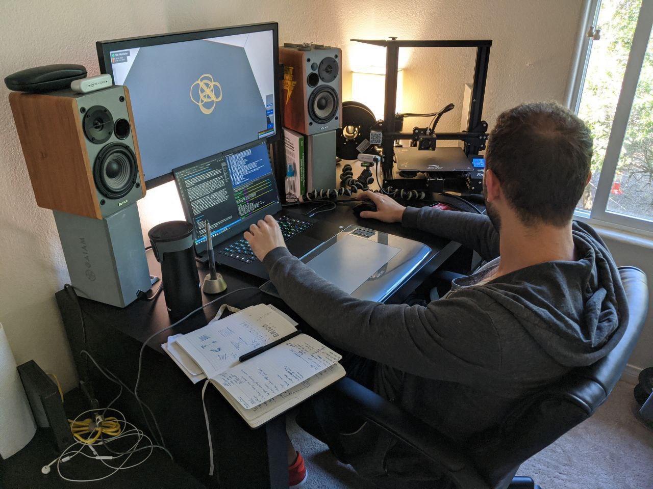
Before the COVID-19 matured into a pandemic, we signed up for this class, anticipating access to fabrication studios. However, shelter-in-place orders made it harder, and every student was lucky enough to receive a loaner FDM printer, Creality Ender 3 Pro. This way, we had personal access to these printers and enabled us to explore digital fabrication with more confidence.
During this quarantine, weekly assignments kept me busy with design and geometry from both the research and aesthetic perspectives. These assignments definitely proved useful in restoring my sanity. Revisiting CAD was exciting as I haven't worked with it for more than 10 years, better yet this time I can use computational geometry for fabrication.
The CAD plays an important role in Computer-Aided Modeling (CAM) pipelines as tools need precise path information to fabricate structurally meaningful objects. Throughout the quarter, we talked about various implications of CAM pipelines on craftsmanship and agency and discussed systems that question the nature of this divide. Cheatle [1] and Zoran [2] take two different approaches (cautious and embracing, respectively) on incorporating digital fabrication into craft studios. On a different note, Jacobs [3] investigates the creative potential of drawing interfaces with scriptable brush definitions.
A number of researches report their findings with interactive fabrication systems that examine the gap between traditional "passive" CAD pipeline and more "active" methods of interaction. Turn-by-wire [4], all three systems described by Willis, et. al. [5], and Shaper Origin [6] enable makers to actively participate in the design and fabrication process by examining various ways of trading precision over user control. Devendorf [7] explains a setup where people collect their desired material from the environment (found-objects) and follows a GCode-operated laser pointer to fabricate their desired model. And, finally, Peng [8] augments the interactive fabrication by introducing AR views and collaboration with a robot arm while actively participating in the design process.
These publications/products and my non-finished assignment about GCodes inspired me to create Materializer, to investigate an interactive fabrication system that offers new affordances and proves useful for teaching novices about fabrication technologies.
Software Development: Drawing Interface and Back-end
Front-end:
The sketching interface is responsible for issuing nozzle movement commands according to strokes drawn on the interface (see the repository for details about keyboard shortcuts).
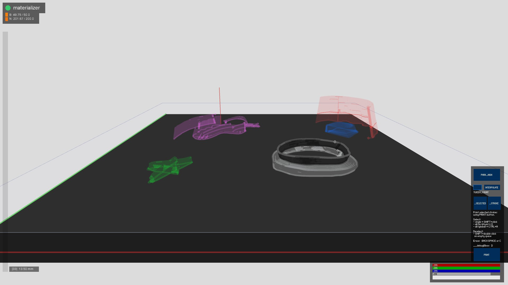
The "on-demand printing" mode described in the introduction (as opposed to "immediate" mode) requires a framework that allows the selection of objects. Likely I had already used selection in 3D space in Processing before. I adapted the code snippet here and added boundary boxes for the current drawing layer and all lines that form the strokes. If selection becomes a problem, the debug view ('D') will show the bounding boxes.
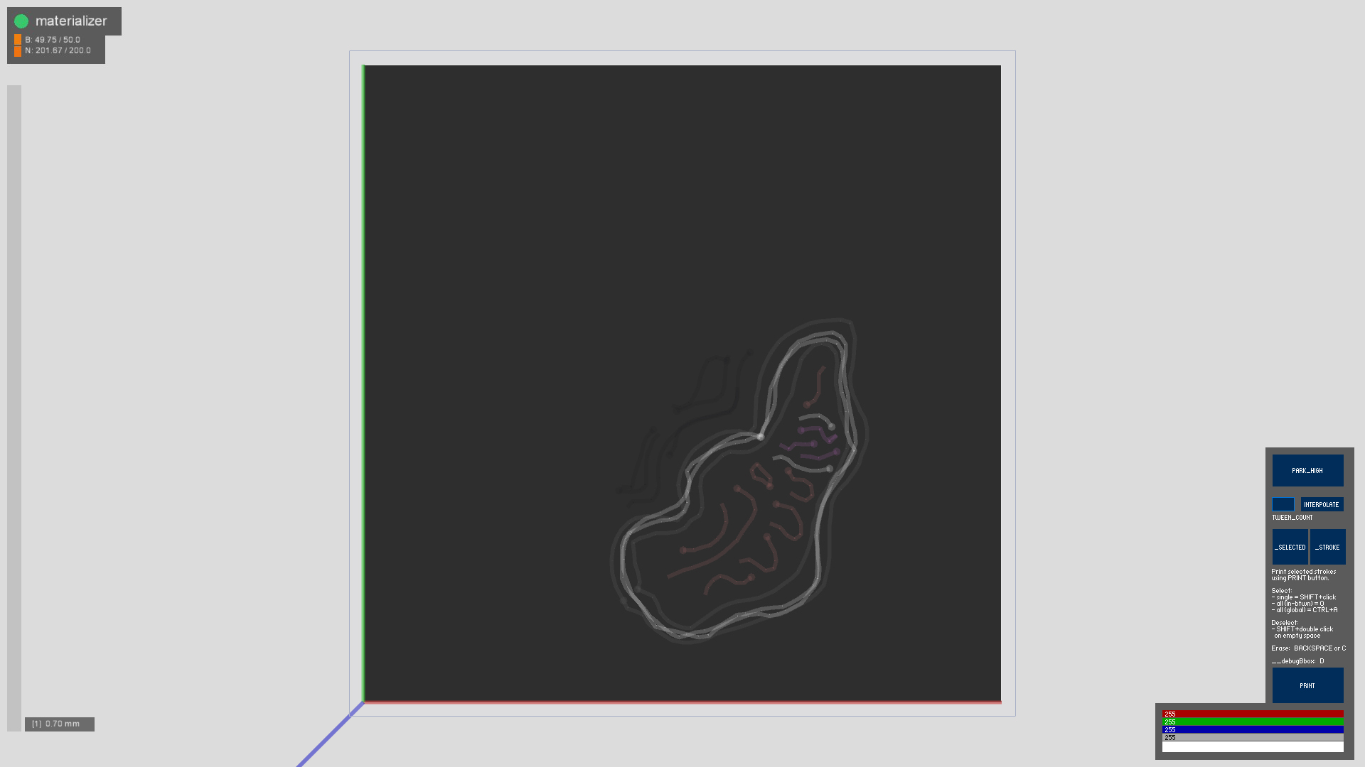
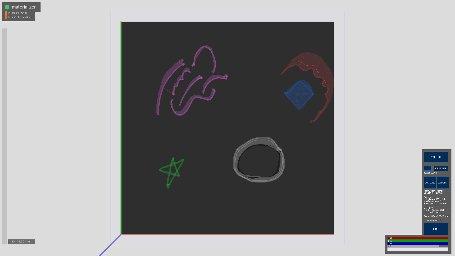
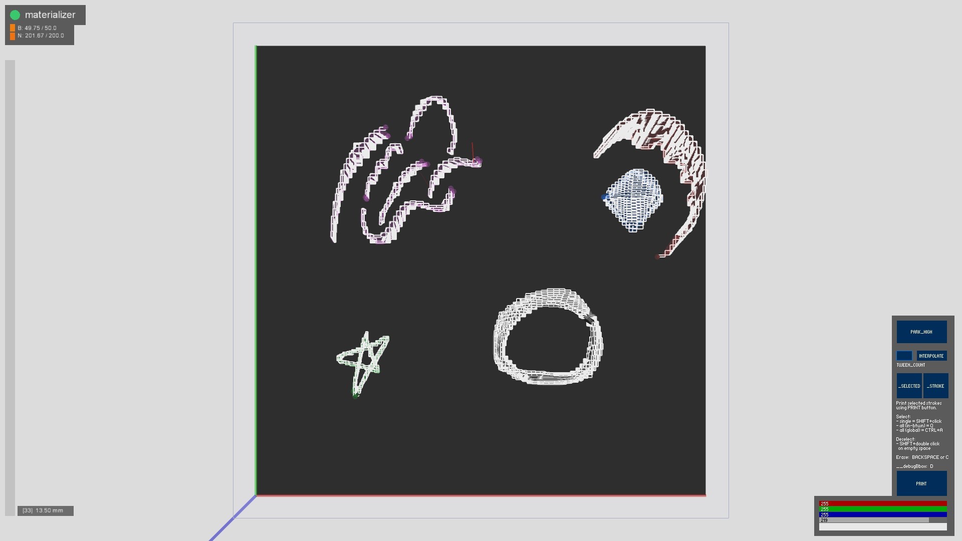
Since the drawing primitives of this interface are the strokes (i.e. lines or curves), creating surfaces or aligning layers was a challenge. I found generating interpolated lines between two strokes useful, and fairly easy to implement. When I think about a 3D shape in this system, I think about its lower and upper bounds in any direction; or the pieces of that geometry that can be broken down into parts that can be described this way. In Figure 1, the hand-drawn curves are highlighted. The rest of the 3D structure is generated by interpolating in-between 'selected' tuples of highlighted curves by aligning the maximum amount of lines determined by the layer height (I used 0.3-0.4mm). These line interpolations can then be printed in batch mode to receive well-aligned layers and clean extrusion.
One important thing to keep in mind that the drawing order of the lines matters. Each stroke is marked with a dot at the end that denotes the end of the stroke. Interpolation currently acts in accordance with this limitation, so interpolating strokes with the opposite direction will cause overlapping lines.
The latest major breakthrough in implementation was a fix in the GCode scheduler. I realized that I am transmitting GCode lines to the printer way to fast. This problem was causing unstable performance and non-ideal extrusion. Currently, a multi-threaded scheduler literally waits for the nozzle to arrive at the start position, calculates the amount of time needed to print a specific line (length/(rate/60) seconds), and sleeps for the duration before sending the new vertex position. Unfortunately, this bug fix happened after the class presentations but it definitely empowered me to build more into the software.
The Backend:
The backend system is responsible for a general-purpose network-based control of the 3D Printer nozzle head. It listens to these keys and OSC messages and governs the details of the printer. It can also interpret messages coming from the printer and relay it to the desired software (temperature readings, nozzle position, is connected). This system does not currently schedule the GCode commands as it needs more application-level information.
There are many more settings/implementation details worth mentioning here. I will add those later.
Use Cases
.jpg)
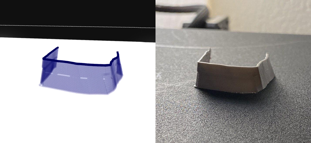
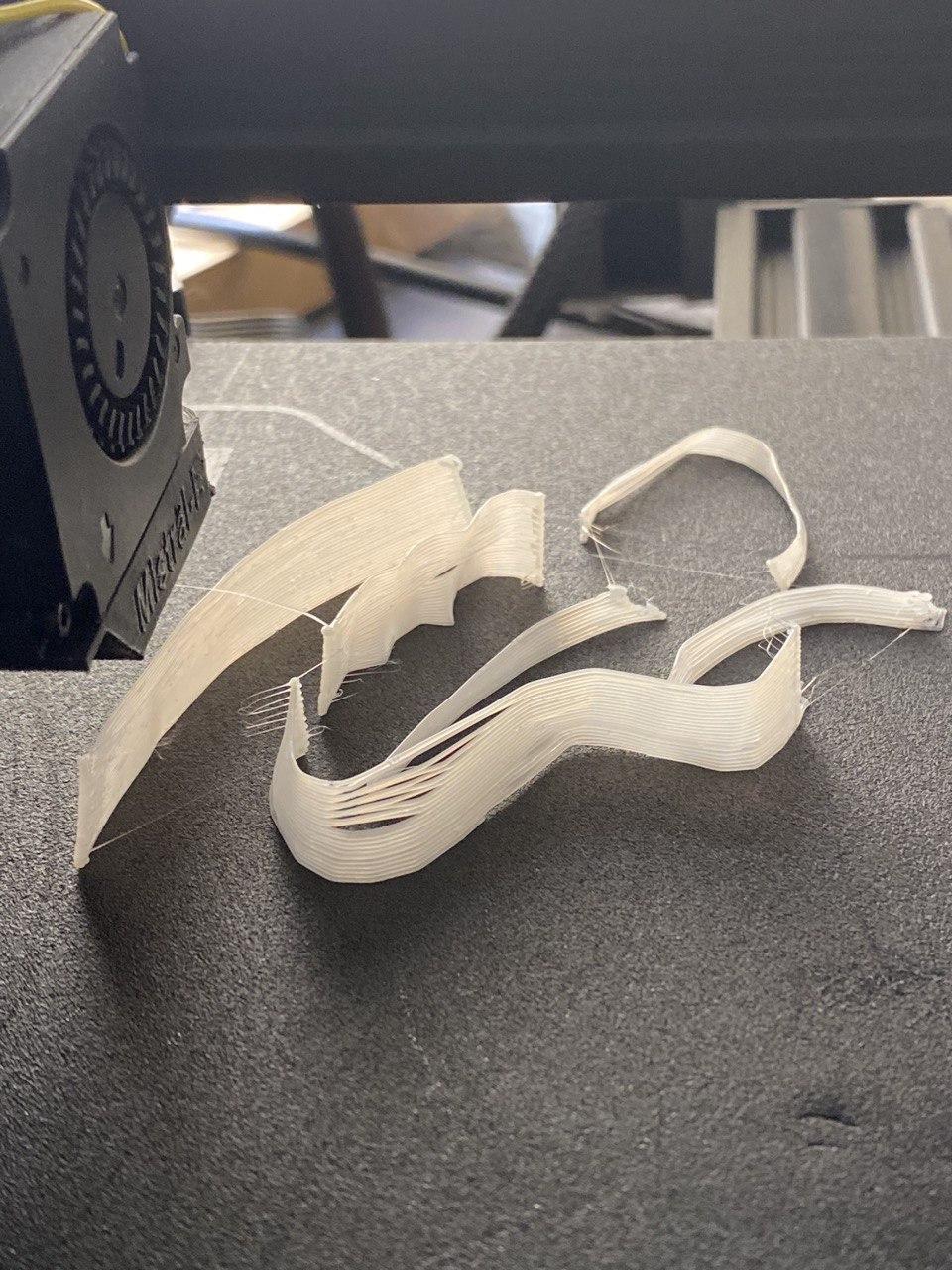
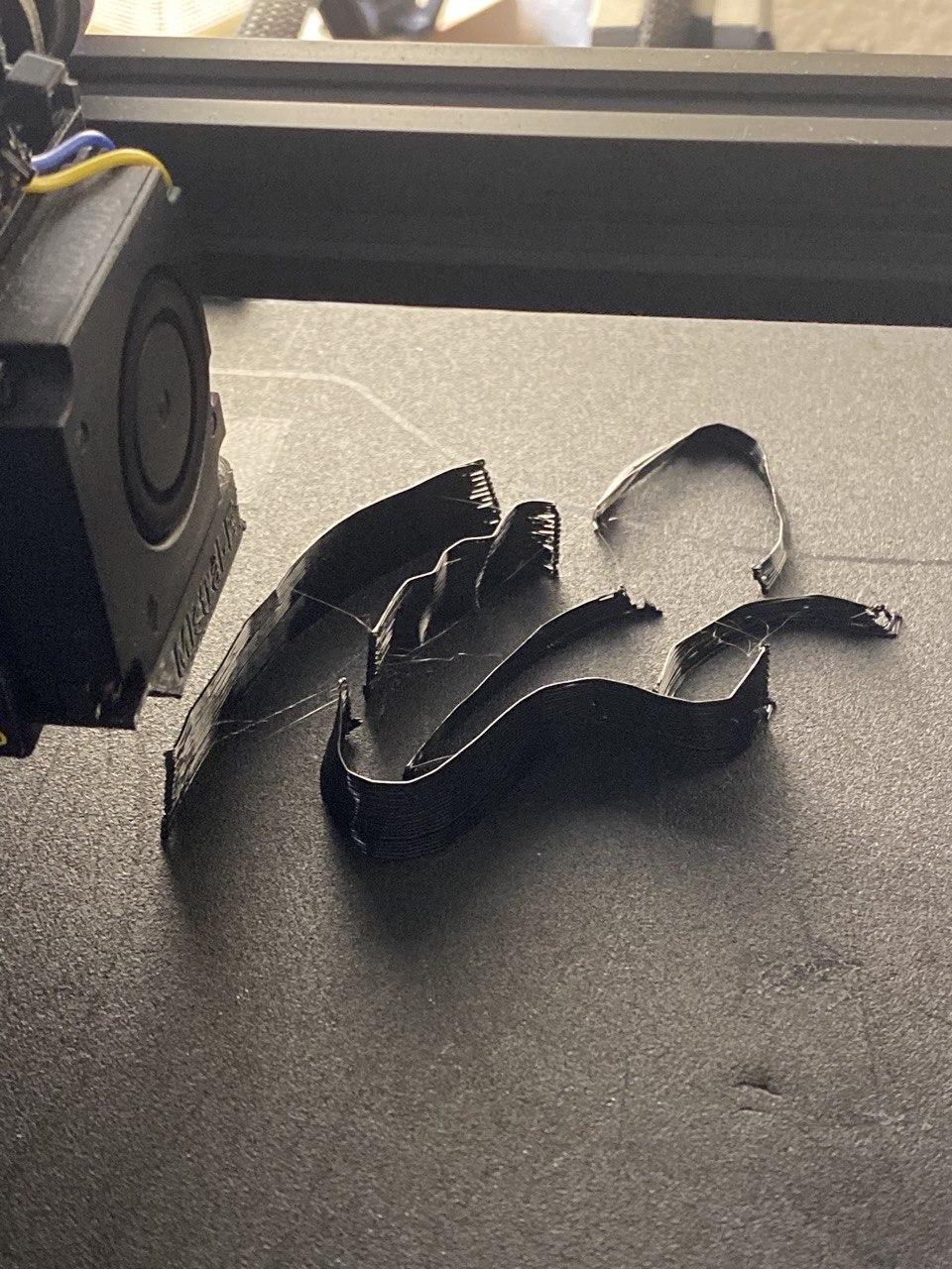
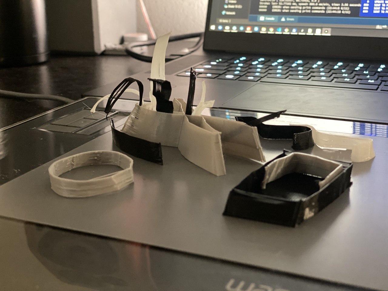
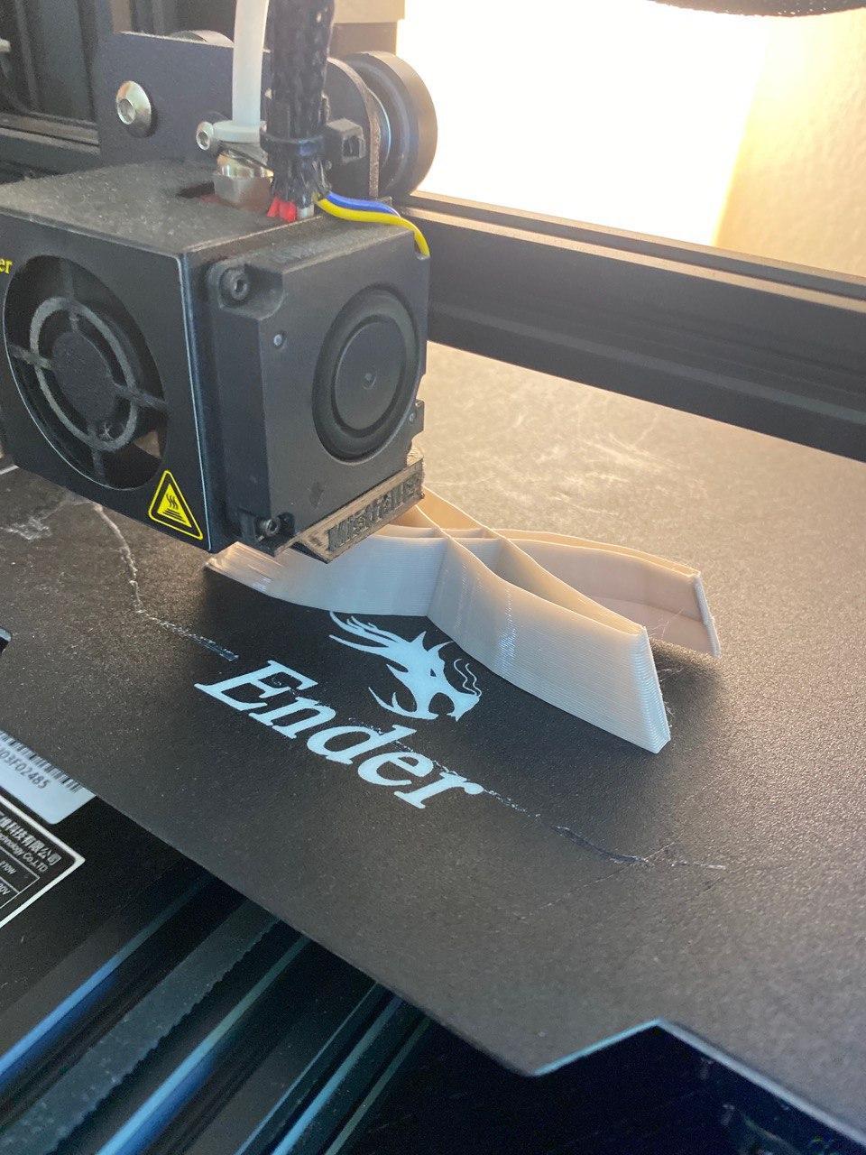
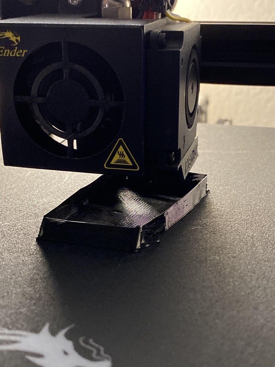
Materializer is built to experiment with non-traditional fabrication pipelines. The interactive nature of the system enables us to operate on an arbitrary height of the 3D printer. This feature provides us the ability to use the whole printer bed as our canvas and sketch/print simultaneously.
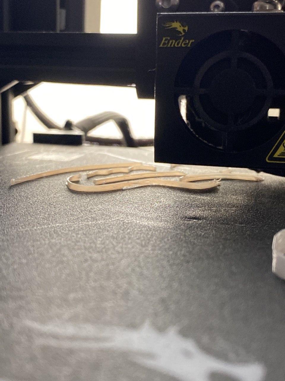
The other property that emerges from the workflow is manually switching the filament spool with a different color for multi-colored artifacts. I haven't had time to finish a prototype using this method, but this procedure should work: (1) print a part of the model with one color, (2) send extruder away from the model, (3) change the filament spool, (4) extrude on the side to remove initial material, (5) select the color of new filament on the interface, (6) sketch and print the rest of the model with new filament color.
I used the following parameters for my prints:
- 0.3 mm layer height
- 600 mm/min first layer rate
- 800 mm/min normal rate
- 3000 mm/min for non-extrusion movements
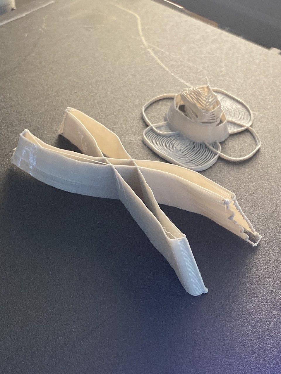
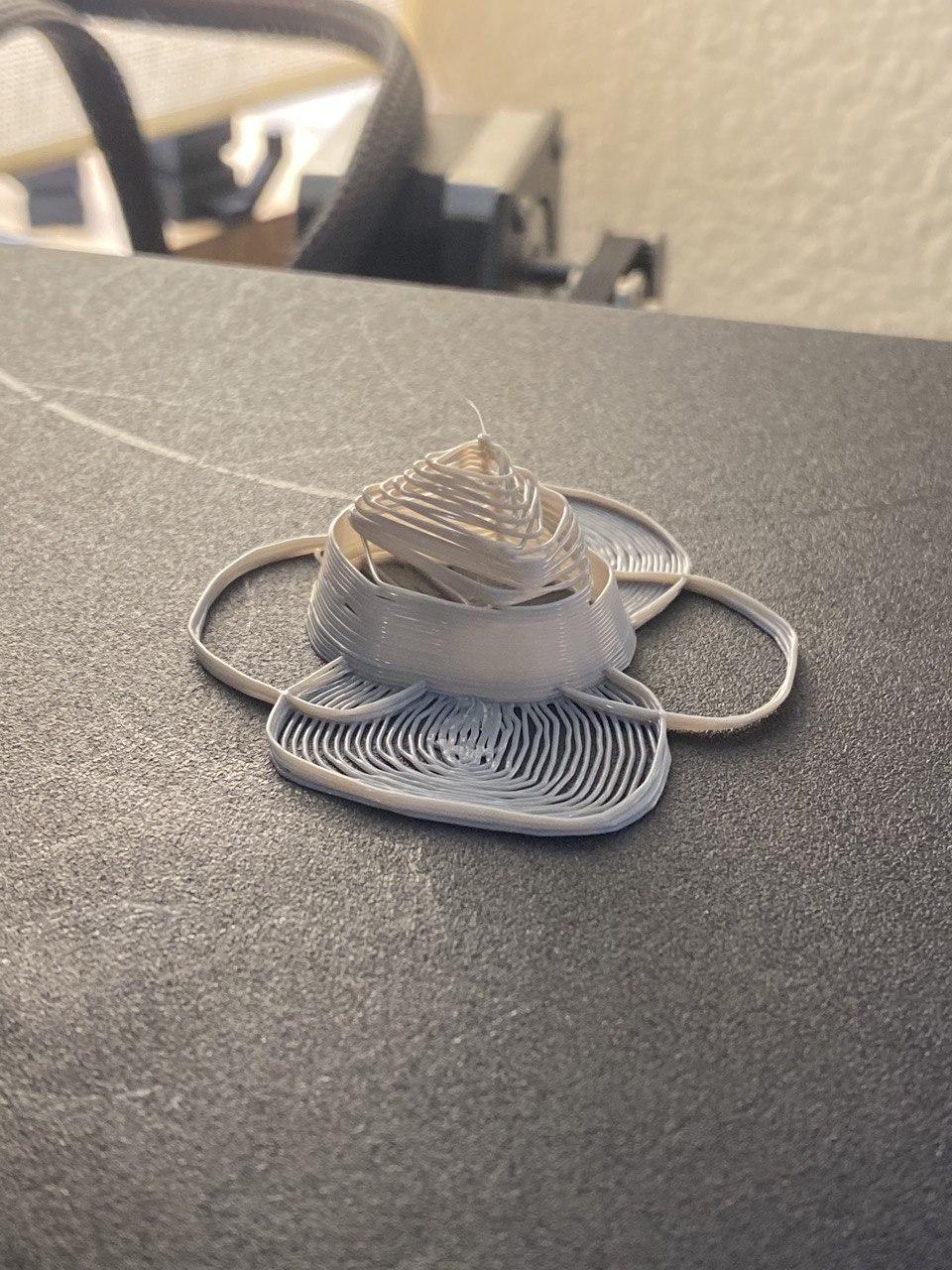
As it is clearly visible from the examples, the 3D form emerges nicely but the details are lost. The lack of precision due to reducing the number of stroke vertices also contributes to not-aligned parts. Once I implement the layer alignment and spatial searching, the system can use this information to modulate parameters like fan speed and printing rate.
Discussion, Limitations & Future Work
Discussion:
- The software needs user testing to evaluate possible contributions.
- I found slowing down and working on a prototype with immediate mode calming and therapeutic, yet it sacrifices from the precision a lot. An alignment feature is needed. Yet I also found the aesthetics of working with imprecise geometry (sketches) and extruding them in the Z dimension to get close-to-perfect layer alignment in for the height.
- Since this final project is developed in a limited time, the software development cycle has informed by practical ideas and personal inspirations rather than relying on a need-finding study. Future iterations of the system could benefit from such an investigation.
Limitations:
- Allowing one type of primitive (line) is limiting.
- The interface is not expressive enough yet: Native iPad version with multi-touch and Apple Pencil support would be interesting.
- When interpolating two curves on the same XY plane, I use the closest distance of the shapes to decide how many strokes are needed. Since the curves can be completely arbitrary, this method does not necessarily result in a completed surface.
- No layer alignment on "immediate" printing mode limits its usability.
Future Work:
- "Immediate mode" needs to work while the user is drawing the stroke, not after
- Check layers in all directions for better calculating the adhesion and supports requirements (spatial search)
- Detect nozzle collision with A* pathfinding algorithm
- Save/Load