MatLab Lung Segmentation
By: Phuc Lam, Paul Yeung, Eric Reyes
-------------------------------------------------------------------------
Acknowing that errors in lungs segmentation will produce false information regarding the identification of a disease area and can directly affect the diagnosis process. Modern computer-aid techniques failed to deliver accurate results when lung diseases have challenging shapes. These abnormal shapes can be caused by pleural effusions, consolidations, etc. Applying the lung segmentation technique, in which the boundaries of the lung are isolated from surrounding thoracic tissue, our app can identify the boundaries with the user's input thresholds to give fully customizable views of the shapes of the lungs,
The purpose of this MatLab project is to create a user-friendly interactive lung segmentation app to detect pathologic conditions of the lungs' X-ray images. Our aim is to create a more effective way to illustrate and identify abnormal lungs in order to give doctors and radiologists a more reliable way to diagnose lung diseases. Using the app designer tool in MatLab, the program is designed to work specifically with chest x-ray and computed tomography (CT) scans, but it is also tested to work with MRI scans.
The instructions below contain our noise filtering technique ( low-pass Wiener filter) as well the image threshold (by using the intensity histogram of the grayscale image) and using a morphological gradient ( the difference between the dilation and the erosion of an image) to identify a region of interest. The instruction will then explain how we integrate all the elements into the graphic user interface (GUI).
-------------------------------------------------------------------------
Note:
1). This project is inspired by a research paper: "Segmentation and Image Analysis of Abnormal Lungs at CT: Current Approaches, Challenges, and Future Trends". Which can be found here
2). We are using X-ray images from NIH: Clinical Center. Link can be found here
3). App designer help can be found here
4). Before running the code: you need to change the Dir path (in line 34) to your file directory and type of image ( line 35 ) (we are analyzing *.png).
Downloads
Step 1: Loading Image
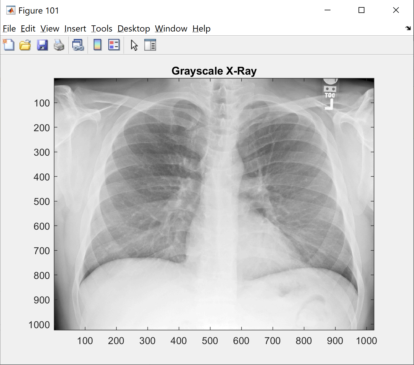
This step will show you the original picture in gray scale. Change the 'name_of_picture.png' to your image name
-------------------------------------------------------------------------
clear; clc; close all;
%% Loading images
raw_x_ray='name_of_picture.png';
I=imread(raw_x_ray);
figure(101);
imshow(I);
colormap(gray);
title('Grayscale X-Ray');
Step 2: Noise Filtering and Histogram
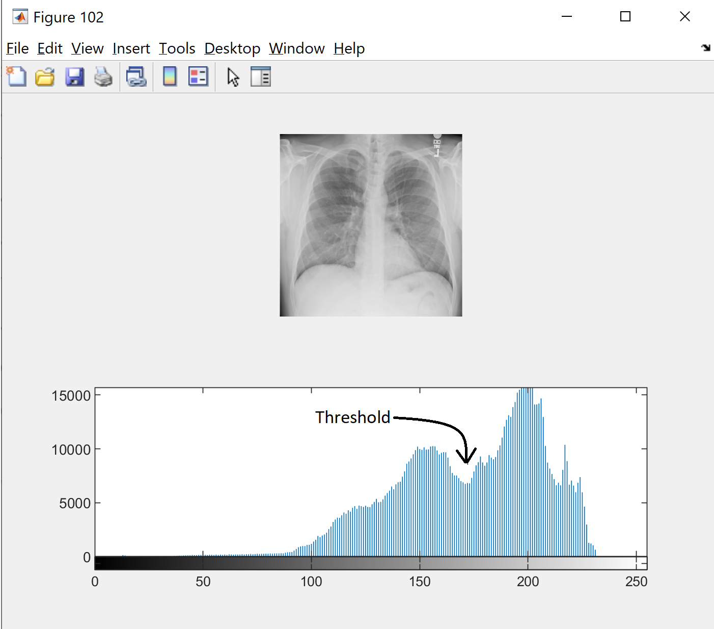
In order to find the threshold for the gray scale image, we look at the histogram to see if a distinct modes. Read more here
-------------------------------------------------------------------------
I=wiener2(I, [5 5]);
figure(102);
subplot(2,1,1);
imshow(I);
subplot(2,1,2);
imhist(I, 256);
Step 3: Setting Thresholds
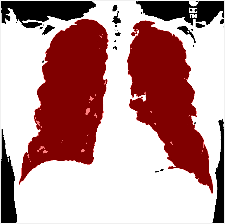
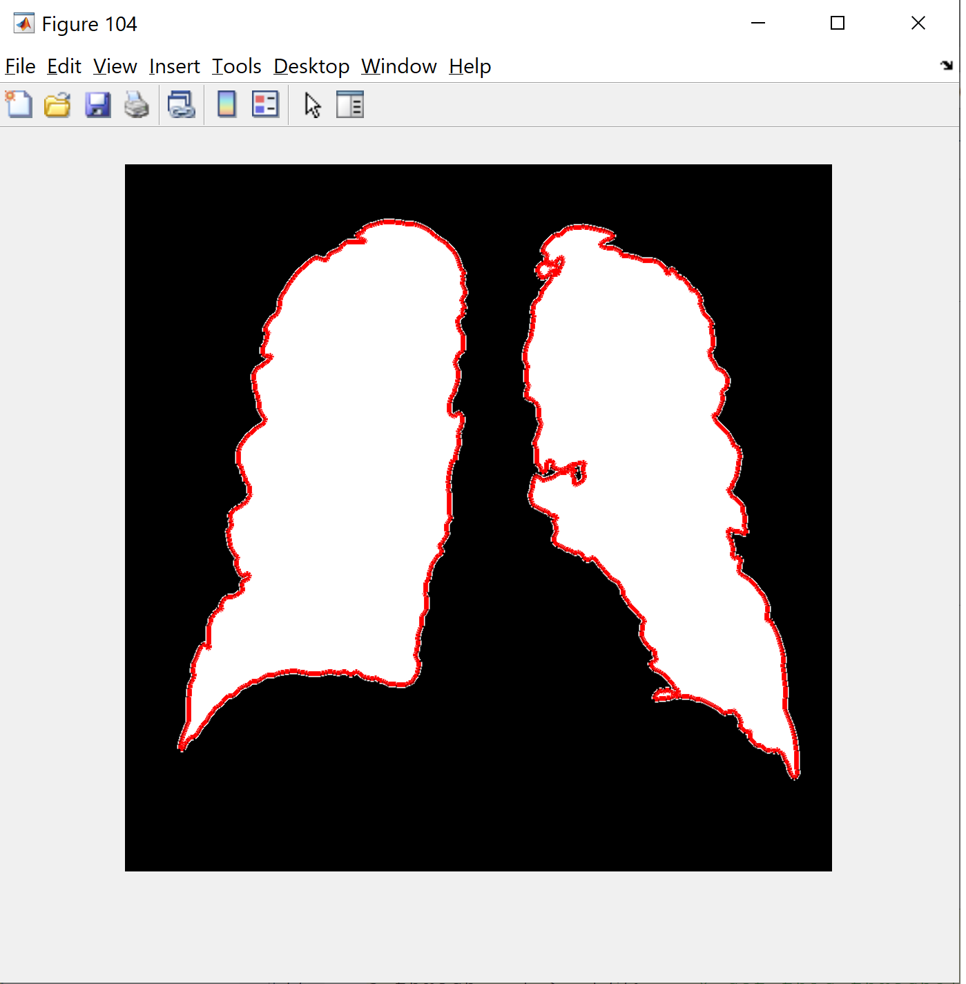
This step allows you to set the threshold according to the histogram. morphologicalGradient will highlight the region of interest in red, and the function visboundaries overlays the outlined and filtered image of the lung in red.
By using regionprops, we can exact the arrays of solidility and sort them in descending. Next i binarize the gray sclae image and apply the morphlogical gradient method and mLoren Shurasking to highlight the region of interest (ROI). The next step is to invert the image so the lung ROI is white in the black background. I use the function showMaskAsOverlay to display 2 mask. Note: the code is inspired from Loren Shure, link.
Lasly, i create red outline by using the bwbwboundaries and masking the filter image and the boundaries.
-------------------------------------------------------------------------
a_thresh = I >= 172; % set this threshold
[labelImage, numberOfBlobs] = bwlabel(a_thresh);
props = regionprops(a_thresh,'all');
sortedSolidity = sort([props.Solidity], 'descend');
SB = sortedSolidity(1);
if SB == 1 % SB only accept solidity == 1 filter out bones
binaryImage = imbinarize(I); figure(103);
imshow(binaryImage); colormap(gray);
SE = strel('square',3);
morphologicalGradient = imsubtract(imdilate(binaryImage, SE),imerode(binaryImage, SE));
mask = imbinarize(morphologicalGradient,0.03);
SE = strel('square',2);
mask = imclose(mask, SE);
mask = imfill(mask,'holes');
mask = bwareafilt(mask,2); % control number of area show
notMask = ~mask;
mask = mask | bwpropfilt(notMask,'Area',[-Inf, 5000 - eps(5000)]);
showMaskAsOverlay(0.5,mask,'r'); % you have to download app/function showMaskAsOverlay
BW2 = imfill(binaryImage,'holes');
new_image = BW2 ;
new_image(~mask) = 0; % invert background and holes
B=bwboundaries(new_image); % can only accept 2 dimensions
figure(104);
imshow(new_image);
hold on
visboundaries(B);
end
Creating GUI
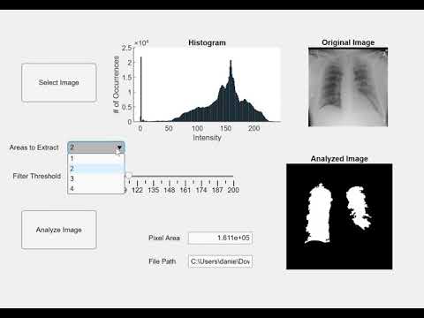
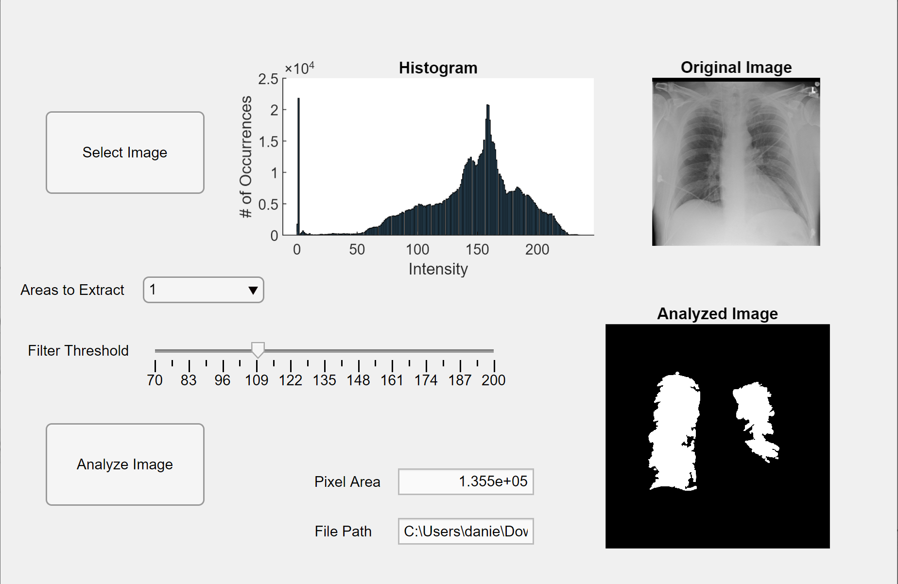
Now, we integrate the prior code into a MATLAB app. Open the App Designer in MATLAB (New > App). First, we design the interface by click-hold-and dragging in three axes into the center workspace. Next, we click-hold-drag two buttons, one edit field (text), one edit field (numeric), one slider, and one drop-down menu. Two axes will each display the preview and analyzed the image, and the third axes will display a histogram of pixels for the preview “selected” image. The edit field (text) box will display the file path of the selected image, and the edit field (numeric) will display the detected pixel area of the lungs.
Now switch from design view into code view in App Designer. Enter in the code the code for properties by clicking the red “Properties” button with a plus sign by it. Initialize the properties I, threshold, and regionsToExtract as in the code provided below. Next, right-click a button in the upper right side of the workspace (the Component Browser) and go from Callbacks>Go to… callback. Add the code for “function SelectImageButtonPushed(app, event).” This code allows you to select an image to analyze from your computer using uigetfile. After selecting an image, a preview image will appear under the axes accompanied by a histogram. Then, right-click the other button and repeat the same procedure to create a callback function.
Add in the code underneath “function AnalyzeImageButtonPushed(app, event).” This code will perform the pixel counting and blob detection on the preview image upon the analyze image button (whichever one you right-clicked for this code). After programming the buttons, we will now program the slider and the drop-down menu. Right-click the slider, create a callback function and add in the code beneath “function FilterThresholdSliderValueChanged(app, event)” until the end. This allows the slider to adjust the gray-intensity threshold.
Create a callback function for the drop down menu, and add in the code beneath “function AreastoExtractDropDownValueChanged(app, event)” to allow the drop down menu to modify the number of blobs displayed on the analyzed image axes. Now, click each entity in the Component Browser and change their properties to your liking, such as changing names of the entities, removing axes, and changing the scaling. Drag and drop the entities of the Component Browser in Design View to a functional and easy-to-understand layout. You now have an app in MATLAB that can analyze images of lungs for pixel area!
-------------------------------------------------------------------------
properties (Access = private)
I = []; % image file
threshold = 257; %threshold for binarizing gray intensity
regionsToExtract = 2;
end
function SelectImageButtonPushed(app, event)
clc;
Dir = 'C:\Users\danie\Downloads\images_004\images'; %define invariate file "prefix"
[imageExt, path] = uigetfile('*.png'); %grab the variable part of the image name
imageName = [Dir filesep imageExt]; %concatenate invariate and variable straings
app.I = imread(imageName); %read the image
imshow(app.I,'parent',app.UIAxes); %display the image
app.FilePathEditField.Value = path ; %display file path of where original image came from
end
function AnalyzeImageButtonPushed(app, event)
originalImage = app.I;
originalImage = wiener2(app.I, [5 5]); %dot-removal filter
histogram(app.AxesHistogram,app.I, 256); %display histogram of image
a_thresh = originalImage >= app.threshold; % set this threshold
labelImage = bwlabel(a_thresh);
props = regionprops(a_thresh,'all');
sortedSolidity = sort([props.Solidity], 'descend');
SB = sortedSolidity(1);
if SB == 1 % SB only accept solidity ==1 filter out bones
SE = strel('square',3);
morphologicalGradient = imsubtract(imdilate(labelImage, SE),imerode(labelImage, SE));
mask = imbinarize(morphologicalGradient,0.03);
SE = strel('square',2);
mask = imclose(mask, SE);
mask = imfill(mask,'holes');
mask = bwareafilt(mask,app.regionsToExtract);
% control number of area show
notMask = ~mask;
mask = mask | bwpropfilt(notMask,'Area',[-Inf, 5000 - eps(5000)]);
BW2 = imfill(labelImage,'holes');
new_image = BW2 ;
new_image(~mask) = 0;
B = bwboundaries(new_image); % can only accept 2 dimensions imshow(new_image,'parent',app.UIAxes2);
hold(app.UIAxes2,'on');
visboundaries(B);
set(gca,'YDir','reverse');
lungArea = bwarea(new_image);
app.PixelAreaEditField.Value = lungArea;
end
end
function FilterThresholdSliderValueChanged(app, event)
app.threshold = app.FilterThresholdSlider.Value;
end
function AreastoExtractDropDownValueChanged(app, event)
stringNumber = app.AreastoExtractDropDown.Value;
app.regionsToExtract = str2double(stringNumber);
end
end
Video Demo
