Master-Slave Communication Between Arduino Boards Using HC-05 Bluetooth Modules

by Rachana Jain in Circuits > Arduino

135 Views, 2 Favorites, 0 Comments

Master-Slave Communication Between Arduino Boards Using HC-05 Bluetooth Modules
Master and Slave communication between two Arduino Boards using HC-05 Bluetooth Modules .png

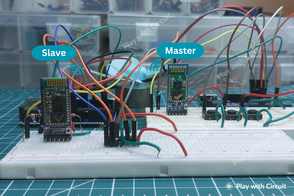
Bluetooth communication is a popular method for wirelessly connecting electronic devices. In this instructable, we’ll demonstrate how to configure two HC-05 Bluetooth modules as master and slave and establish communication between two Arduino boards.

This tutorial includes:

  1. Configuring HC-05 modules using AT commands
  2. Wiring diagrams for master and slave circuits
  3. Arduino codes for master and slave boards
  4. Step-by-step explanation of master-slave communication

Supplies

2 x Arduino UNO boards

2 x HC-05 Bluetooth modules

2 x Breadboards

Jumper wires

4 x1k and 2k resistors

12V Supply Adapter

DC Fan

3 Push Buttons

Configuring the HC-05 Bluetooth Modules Using AT Commands
Slide1.JPG

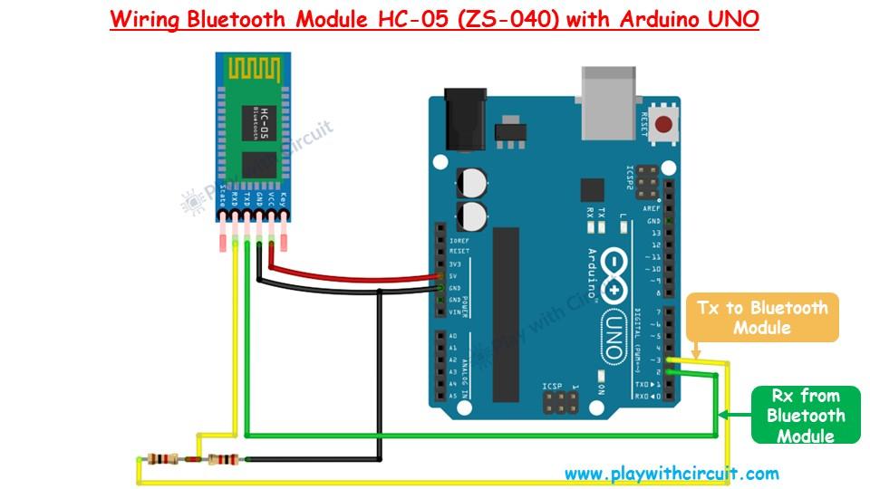
To configure the HC-05 Bluetooth modules, we first need to connect them to a PC via an Arduino board and use the Serial Monitor in the Arduino IDE to send AT commands. The connection setup between the HC-05 module and Arduino UNO is shown in image.

The HC-05 module communicates through a serial UART interface, but Arduino UNO's built-in serial interface is used for uploading code. To resolve this, we reassign Arduino pins 2 and 3 as software-based Tx and Rx communication lines.

Voltage Level Conversion for HC-05 Rx Pin

The Rx pin of the HC-05 module is not 5V tolerant, so a voltage divider circuit is used to step down the voltage to 3.3V. This is achieved using two resistors (1kΩ and 2kΩ) in the following manner:

  1. Connect a 1kΩ resistor and a 2kΩ resistor in series.
  2. The junction of the resistors outputs 3.3V, suitable for the Rx pin of the HC-05.

The module’s Vcc and Gnd pins are connected to the 5V and Gnd pins of the Arduino, respectively.

Code

This code facilitates communication with Bluetooth Module HC-05 and we will be able to configure the Bluetooth module using Arduino’s Serial Monitor.

To ensure this code functions correctly, follow these steps to put the Bluetooth module into Command Mode:

  1. Press and hold the button located on the Bluetooth module above the EN (Enable) pin before powering up the module.
  2. While continuing to hold the button, power on the module.
  3. Keep the button pressed for at least 2 seconds after powering up, then release it.
/*
Interfacing HC-05 (ZS-040) Bluetooth Module with Arduino UNO using pin 2(Rx) and 3(Tx)
by www.playwithcircuit.com
For this code to work make sure to press the button on the Bluetooth module above the Enable pin before powering the module and press it for at least 2 sec after powering up the module then release it. This will put the Bluetooth module in Command Mode.
*/
// Include Soft Serial Library. This library makes DIO pins as Serial Pins
#include <SoftwareSerial.h>
//Create software serial object to communicate with HC-05
SoftwareSerial BT_Serial(2, 3); // Now pin 2 and pin 3 of Arduino are Serial Rx & Tx pin respectively.
char serialInputArray[100];
int counter = 0; // Counter for getting data from bluetooth module
void setup() {
// Open serial communication at baudrate 9600
Serial.begin(9600);
delay(100); // delay before sending the data
Serial.println("Initializing Bluetooth Module in Command Mode\n");
// Open the soft Serial port and set the data rate for the SoftwareSerial port at 38400 to communicate with Bluetooth Module in Command Mode
BT_Serial.begin(38400);
delay(100);
// Send data to HC-05 Bluetooth Module
BT_Serial.print("AT");
printCRLF_Bluetooth();
// Check if data is available on Bluetooth Serial Port
do {
delay(10);
// If counter is greater than 300 i.e., 3000 ms has passed then break out of Loop
if (counter++ > 300) {
break;
}
} while (BT_Serial.available() == 0);
// If counter is greater than 300 i.e., 3000 ms has passed and data is not received
if (counter > 300) {
errorMsg();
} else {
counter = 0;
do {
serialInputArray[counter++] = BT_Serial.read();
delay(10); // delay for 10 ms for getting response if the Module is slow
} while (BT_Serial.available() != 0);
if (memcmp(serialInputArray, "OK", 2) == 0) {
Serial.print("Bluetooth Module is Successfully Initialized in Command Mode\n");
} else {
errorMsg();
}
}
}
void loop() { // run over and over
counter = 0;
memset(serialInputArray, 0x00, 100);
// Get Data From Serial Terminal
do {
// Wait Here for getting cmd from Serial Terminal
} while (Serial.available() == 0);
Serial.readBytesUntil(0x0D, serialInputArray, 100); // this '0x0D' is not added to buffer serialInputArray[]
// Flush Data available in Serial buffer of Arduino
flush();
//Return that Data to PC
printCRLF();
Serial.print("Cmd :");
Serial.print(serialInputArray);
printCRLF();
// Send data to HC-05 Bluetooth Module
BT_Serial.print(serialInputArray);
printCRLF_Bluetooth();
// Wait for at least 3 seconds to get data
do {
delay(10);
// If counter is greater than 300 i.e., 3000 ms has passed then break out of Loop
if (counter++ > 300) {
break;
}
} while (BT_Serial.available() == 0);
// If counter is greater than 300 i.e., 3000 ms has passed and data is not received
if (counter > 300) {
Serial.print("RSP :Invalid Command");
printCRLF();
} else {
Serial.print("RSP :");
// Get Data From HC-05 and push to Serial Monitor
do {
Serial.write(BT_Serial.read());
delay(10); // delay for 10 ms for getting response if the module is slow
} while (BT_Serial.available() != 0);
}
}
// This function sends "\n\r" after Every Command to Bluetooth
void printCRLF_Bluetooth() {
BT_Serial.write(13); // Carriage Return '\r'
BT_Serial.write(10); // Line Feed '\n'
}
// This function sends "\n\r" after Every Command to Serial Terminal
void printCRLF() {
Serial.write(13); // Carriage Return '\r'
Serial.write(10); // Line Feed '\n'
}
// Flush Data available in Serial buffer of Arduino
void flush() {
do {
Serial.read();
delay(10);
} while (Serial.available() != 0);
}
// Error MSG when Communication with Bluetooth Module is not possible
void errorMsg() {
Serial.print("Bluetooth Module is not Initialized in Command Mode, press button on Bluetooth Module\n");
Serial.print("and then restart the Arduino and Module supply. Press it for at least 2 secs after powering up the module then release it.\n");
Serial.print("This will put the Bluetooth module in Command Mode\n");
Serial.print("Check the connections, maybe connections are faulty\n");
Serial.print("If Everything is OK then Module may be faulty\n");
printCRLF();
while (1);
}

Putting Bluetooth Module in Command Mode

To assign the HC-05 Bluetooth module a specific role (Slave or Master), it must first be put into Command Mode to accept AT commands. Follow these steps carefully:

Step 1: Wire the Bluetooth Module

Connect the HC-05 module to the Arduino UNO as per the circuit diagram. Ensure proper connections, including the voltage divider for the module's Rx pin, and upload the code to the Arduino.

Step 2: Disconnect the USB Cable

Once the code is successfully uploaded, disconnect the USB cable from the Laptop/PC to ensure the Arduino restarts properly during the next steps.

Step 3: Configure the Serial Monitor Settings

  1. Open the Serial Monitor in the Arduino IDE.
  2. Set the baud rate to 9600,n,8,1 (9600 baud rate, no parity, 8 data bits, 1 stop bit).
  3. Choose the "Both NL & CR" option for Line Ending.

Step 4: Press the Button on the Bluetooth Module

  1. Hold down the button on the HC-05 module (located above the Enable pin).
  2. While holding the button, reconnect the USB cable to the Laptop/PC to power the Arduino.

Step 5: Wait for Confirmation

Keep the button pressed until a message appears in the Serial Monitor indicating that the module is in Command Mode.

This confirms that the module is ready to receive AT commands for configuring its role as Master or Slave.

Configuring the Bluetooth Module for the Slave Role

Once the HC-05 module successfully enters Command Mode, follow these steps to configure it as a Slave:

Step 1: Test Communication

  1. Open the Serial Monitor in the Arduino IDE.
  2. Type AT and press Enter.
  3. The module should respond with OK, indicating successful communication between the module and the Arduino.

Step 2: Change the Module Name

  1. To rename the module, type: AT+NAME=SLAVE
  2. Press Enter.
  3. The response should be OK, confirming the name change.

Step 3: Set the Role to Slave

  1. To assign the module the Slave role, type: AT+ROLE=0
  2. Press Enter.
  3. The module will respond with OK, confirming the role assignment.

Step 4: Set Connection Mode

  1. To set connection mode, type “AT+CMODE=0” and press Enter 
  2. You should receive “OK” as a response.

Step 5: Retrieve the Module Address

  1. To get the module's unique address, type: AT+ADDR?
  2. Press Enter.
  3. The address will be displayed in hexadecimal format (e.g., 1234:56:7890AB).
  4. Note down this address, as it is required for configuring the Master module.

Step 6: Disconnect the Slave Module

  1. Once the configuration is complete, disconnect the USB cable from the PC/Laptop.
  2. Remove the Slave HC-05 module from the circuit to prevent interference during the Master configuration process.

The HC-05 module is now configured as a Slave and ready to pair with a Master module for communication.

Configuring the Bluetooth Module for the Master Role

Follow these steps to configure another HC-05 module for the Master role:

Step 1: Enter Command Mode

Connect the HC-05 module to the circuit, and place it into Command Mode the same way as done for the Slave module. The slow blinking LED confirms that the module is in Command Mode.

Step 2: Verify Communication

  1. Open the Serial Monitor in the Arduino IDE.
  2. Type AT and press Enter.
  3. If the communication is successful, the module will respond with OK.

Step 3: Rename the Module

  1. To set the module's name, type: AT+NAME=MASTER
  2. Press Enter.
  3. The response OK confirms the name has been updated successfully.

Step 4: Assign the Role as Master

  1. To configure the module as the Master, type: AT+ROLE=1
  2. Press Enter.
  3. If successful, the module will reply with OK.

Step 5: Set Fixed Connection Mode

  1. To ensure the module connects to a specific address, type: AT+CMODE=0
  2. Press Enter.
  3. The module will respond with OK, indicating the connection mode is set to fixed.

Step 6: Pair the Master with the Slave

  1. Type the following command, replacing the address with the actual address of your Slave module:
  2. AT+BIND=0021,13,03BB60
  3. Replace 0021,13,03BB60 with the address of the Slave module.
  4. In this example, the Slave address is 21:13:3bb60.
  5. Press Enter.
  6. The module will respond with OK, confirming the pairing.

Step 7: Verify the Paired Address

  1. To check if the correct address is bound, type: AT+BIND?
  2. Press Enter.
  3. The response should display the bound address. If all zeroes or an incorrect address is displayed, repeat Step 6.

Step 8: Disconnect the Module

  1. Remove the USB cable from the PC/Laptop.
  2. Safely detach the Master HC-05 module from the circuit.

Your Master module is now configured and ready for communication with the Slave module.

Master-Slave Communication Between Two Arduino Boards Using HC-05 Bluetooth Modules
Slide5.PNG
Wiring-Diagram-of-Slave-Arduino.png

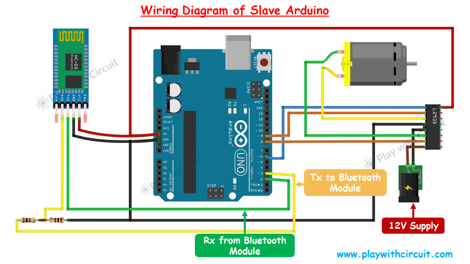
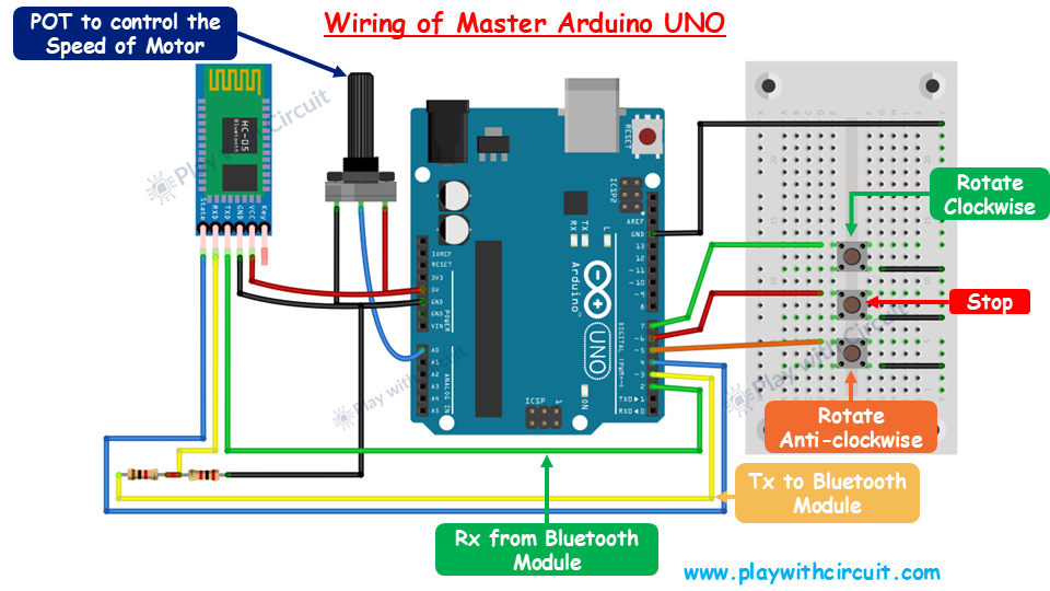
Now, let’s establish wireless communication between two Arduino UNO boards using the HC-05 Bluetooth modules.

We will set up two separate circuits: one for the Master device and another for the Slave device. The Master device will send commands to the Slave device, and the Slave device will execute the received commands and send a response back to the Master.

Master Arduino Code

This code allows the user to control the motor’s direction (clockwise or anticlockwise) and speed using buttons and a potentiometer connected to the Master Arduino. 

/*
Interfacing HC-05 (ZS-040) Bluetooth Module with Slave Arduino UNO using pin 2(Rx) and 3(Tx) and Control the Motor using another Arduino UNO, which acts as Master
by www.playwithcircuit.com
This is the Master Arduino Code.
*/
// Include Soft Serial Library. This library makes DIO pins as Serial Pins
#include <SoftwareSerial.h>
//Create software serial object to communicate with HC-05
// Now pin 2 and pin 3 of Arduino are Serial Rx & Tx pin Respectively
SoftwareSerial BTSerial(2, 3);
// Define MACROS related to communication
#define START_CHAR '*'
#define END_CHAR '#'
#define MAX_BUFFFER 8
// Define the pins connected to buttons or POT to control the Motor connected with Slave
// button to Rotate motor in Clockwise Direction
#define ROTATE_CLOCKWISE 7
// button to Stop motor
#define ROTATE_STOP 6
// button to Rotate motor in Anticlockwise Direction
#define ROTATE_ANTI_CLOCKWISE 5
// Pot to control motor's Speed
#define ROTATE_SPEED A0
// LED to Indicate successful communication
#define LED_GREEN 13
// State Pin to check if module is connected to Slave
// if state pin is high it means Master module is connected to Slave module
#define STATE_PIN 4
// Declare variables related to communication with Arduino Master
char serialInput;
int dataIndex = 0;
int rspSize = 0;
bool bo_cmd_ok = false;
// Whether the string receiving is completed.
bool dataRcvd = false;
// To receive Raw response
char dataBuffer[MAX_BUFFFER] = { 0 };
// To save exact response
char rspBuffer[MAX_BUFFFER] = { 0 };
// Alive command
const char aliveCmd[MAX_BUFFFER] = {START_CHAR, 'A', 'L', 'I', 'V', 'E', END_CHAR, 0x00};
// Standard OK response
const char stdRsp[5] = {START_CHAR, 'O', 'K', END_CHAR, 0x00};
// Declare variable related to motor control
int motor_Speed = 0;
int motor_direction = 0;
// Function to clear bluetooth Buffer
void flushBTRcv();
// Function to receive Slave's Response
int checkResponse(void);
// Inline function to check if button is pressed packed with debouncing logic
inline bool chkButtonState(int pinNum, int checkState, int debounceDelay) {
if (((digitalRead(pinNum) == checkState) ? true : false) == true) {
delay(debounceDelay);
return (((digitalRead(pinNum) == checkState) ? true : false) == true);
} else {
return false;
}
}
void setup() {
int retVal = 1;
// Initialize motor control pins as INPUTS
pinMode(ROTATE_CLOCKWISE, INPUT_PULLUP);
pinMode(ROTATE_STOP, INPUT_PULLUP);
pinMode(ROTATE_ANTI_CLOCKWISE, INPUT_PULLUP);
pinMode(ROTATE_SPEED, INPUT);
pinMode(STATE_PIN, INPUT_PULLUP);
// Initialize Status LED as OUTPUT and Turn it OFF
pinMode(LED_GREEN, OUTPUT);
digitalWrite(LED_GREEN, LOW);
// Begin the soft Serial port and set the data rate for the SoftwareSerial port at 9600 to communicate with Bluetooth Module in Data Mode
BTSerial.begin(9600);
// wait for state pin to turn HIGH else remain in this loop
while(chkButtonState(STATE_PIN,LOW,0));
do {
// provide a delay of 200 ms
delay(200);
//! Send Alive Command
BTSerial.print(aliveCmd);
retVal = checkResponse();
if (retVal == 1) {
// Turn Green LED OFF
digitalWrite(LED_GREEN, LOW);
} else {
// Turn GREEN LED ON
digitalWrite(LED_GREEN, HIGH);
break;
}
} while (retVal);
}
void loop() {
// variable to read POT input
int potValue = 0;
// return value of function checkResponse()
int retVal = 1;
// Read Motor Direction
// check if Clockwise rotation button is pressed
if (chkButtonState(ROTATE_CLOCKWISE, LOW, 20) == true) {
motor_direction = 1;
}
// check if Anticlockwise rotation button is pressed
else if (chkButtonState(ROTATE_ANTI_CLOCKWISE, LOW, 20) == true) {
motor_direction = 2;
}
// check if Stop rotation button is pressed
else if (chkButtonState(ROTATE_STOP, LOW, 20) == true) {
motor_direction = 0;
}
// Read the value from the potentiometer
potValue = analogRead(ROTATE_SPEED);
motor_Speed = map(potValue, 0, 1023, 0, 255);
//Send Motor Control command to Slave
BTSerial.print(START_CHAR);
BTSerial.print(motor_direction);
BTSerial.print(',');
BTSerial.print(motor_Speed);
BTSerial.print(END_CHAR);
// Check Response
retVal = checkResponse();
if (retVal == 1) {
// Turn Green OFF
digitalWrite(LED_GREEN, LOW);
} else {
// Turn GREEN LED ON
digitalWrite(LED_GREEN, HIGH);
}
// Send next command after 100 ms
delay(100);
}
// Flush Extra character from BT Rx buffer
void flushBTRcv() {
char ret_char;
while (BTSerial.available() > 0) {
ret_char = BTSerial.read();
}
}
// This function is used to receive "*OK#" response from Slave
// If exact response is received it returns 0 else it returns 1
int checkResponse(void) {
int retVal = 1;
int counter = 0;
delay(10); // delay to get first character
// Get Data From HC-05
while (BTSerial.available()) {
// get the new byte
serialInput = BTSerial.read();
dataBuffer[dataIndex++] = serialInput;
// If the incoming character is a END_CHAR character, set a flag so the main loop can do something about it
if ((serialInput == END_CHAR) || (dataIndex == MAX_BUFFFER)) {
dataIndex = 0;
dataRcvd = true;
flushBTRcv();
}
delay(10); // 10 ms delay after receiving every character
if (counter++ > 350) { // this provides delay of 3500 ms or 3.5 seconds
dataRcvd = false;
dataIndex = 0;
flushBTRcv();
break;
}
}
if (dataRcvd == true) {
rspSize = 0;
// Check for start and end character
memset(rspBuffer, 0x00, sizeof(rspBuffer));
// Extract command from RAW data sent
for (int i = 0; i < MAX_BUFFFER; i++) {
if (dataBuffer[i] == START_CHAR) {
for (int j = 0; j < MAX_BUFFFER; j++) {
rspBuffer[j] = dataBuffer[j + i];
rspSize++;
if (rspBuffer[j] == END_CHAR) {
bo_cmd_ok = true;
break;
}
}
}
}
if (bo_cmd_ok == true) {
//! check for Command's Response if its OK it means Slave is connected to Master
if (memcmp(rspBuffer, stdRsp, 4) == 0) {
// Reply OK
retVal = 0;
} else {
retVal = 1;
}
} else {
retVal = 1;
}
dataRcvd = false;
bo_cmd_ok = false;
memset(dataBuffer, 0x00, sizeof(dataBuffer));
} else {
retVal = 1;
}
// reset array and variables
memset(dataBuffer, 0x00, sizeof(dataBuffer));
bo_cmd_ok = false;
dataRcvd =false;
// return result
return retVal;
}

Slave Arduino Code

This code is designed for the Slave Arduino that controls a motor (fan) using commands received from a Master Arduino via an HC-05 Bluetooth module. 

/*
Interfacing HC-05 (ZS-040) Bluetooth Module with Slave Arduino UNO using pin 2(Rx) and 3(Tx) and Control the Fan connected to Motor using another Arduino UNO, which acts as Master
by www.playwithcircuit.com
This is Slave Arduino Code.
*/
// Include Soft Serial Library, this library makes DIO pins as Serial Pins
#include <SoftwareSerial.h>
//Create software serial object to communicate with HC-05
SoftwareSerial BTSerial(2,3); // Now pin 2 and pin 3 of Arduino are Serial Rx & Tx pin respectively
// Define MACROS related to communication
#define START_CHAR '*'
#define END_CHAR '#'
#define MAX_BUFFFER 14
#define MAX_INDEX 2
#define MOTOR_DIRECTION_INDEX 0
#define MOTOR_SPEED_INDEX 1
// Define the pins connected to the L293D IC
#define MOTOR_EN 6 // Enable pin for Motor A
#define MOTOR_IN1 9 // Input 1 for Motor A
#define MOTOR_IN2 8 // Input 2 for Motor A
// Declare variables related to communication with Master Arduino
char serialInput;
int dataIndex = 0;
char databuffer[MAX_BUFFFER] = { 0 };
char cmdbuffer[MAX_BUFFFER] = { 0 };
bool dataRcvd = false; // whether the string receiving is completed.
char char_array[MAX_INDEX][4] = { 0 };
int int_array[MAX_INDEX] = { 0 };
int index;
int cmdsize = 0;
bool bo_cmd_ok = false;
int row = 0;
int row_index = 0;
// Alive command
const char aliveCmd[8] = { START_CHAR, 'A', 'L', 'I', 'V', 'E', END_CHAR, 0x00 };
// Standard OK response
const char stdRsp[5] = { START_CHAR, 'O', 'K', END_CHAR, 0x00 };
// Declare variables related to motor control
int motorSpeed = 0;
char previous_direction = 0; // to store previous direction
bool one_time_flag = true;
int AsciitoInt(char* char_array);
void flushBTRcv();
void setup() {
// Initialize motor control pins as outputs
pinMode(MOTOR_EN, OUTPUT);
pinMode(MOTOR_IN1, OUTPUT);
pinMode(MOTOR_IN2, OUTPUT);
// Begin the soft Serial port and set the data rate for the SoftwareSerial port at 9600 to communicate with Bluetooth Module in Data Mode
BTSerial.begin(9600);
// provide stability delay of 200 ms
delay(200);
// Set initial motor speed to zero
analogWrite(MOTOR_EN, 0);
}
void loop() {
// Get Data From HC-05
while (BTSerial.available()) {
// get the new byte
serialInput = BTSerial.read();
databuffer[dataIndex++] = serialInput;
delay(10); // delay of 10 ms to get next character
// if the incoming character is a END_CHAR character or databuffer is full
// set a flag to true so that buffer shall not overflow
if ((serialInput == END_CHAR) || (dataIndex == MAX_BUFFFER)) {
dataIndex = 0;
dataRcvd = true;
flushBTRcv();
}
}
if (dataRcvd == true) {
cmdsize = 0;
// Check for start and end character
memset(cmdbuffer, 0x00, sizeof(cmdbuffer));
// Extract command from RAW data sent
for (int i = 0; i < MAX_BUFFFER; i++) {
if (databuffer[i] == START_CHAR) {
for (int j = 0; j < MAX_BUFFFER; j++) {
cmdbuffer[j] = databuffer[j + i];
cmdsize++;
if (cmdbuffer[j] == END_CHAR) {
bo_cmd_ok = true;
break;
}
}
}
if (bo_cmd_ok == true) {
break;
}
}
dataRcvd = false;
memset(databuffer, 0x00, sizeof(databuffer));
if (bo_cmd_ok == true) {
//! check for Alive Command
if (memcmp(cmdbuffer, aliveCmd, 7) == 0) {
// Reply OK
BTSerial.print(stdRsp);
bo_cmd_ok = false;
}
}
}
// if command is successfully extracted from data buffer and saved in command buffer
if (bo_cmd_ok == true) {
// Reset all variables and array
index = 0;
row = 0;
row_index = 0;
bo_cmd_ok = false;
memset(char_array, 0x00, sizeof(char_array));
memset(int_array, 0x00, sizeof(int_array));
// as index 0 is the start character hence it is incremented by 1
index++;
// save two different commands in character array, one is motor status and another is motor speed
for (; index < cmdsize; index++) {
if (cmdbuffer[index] == ',' || cmdbuffer[index] == '#') {
row++;
row_index = 0;
continue;
} else {
char_array[row][row_index++] = cmdbuffer[index];
}
}
for (int i = 0; i < MAX_INDEX; i++) {
int_array[i] = AsciitoInt(&char_array[i][0]);
}
// Fan Motor Control
if (int_array[MOTOR_DIRECTION_INDEX] == 1) { // Clockwise case
// this is done when suddenly direction changes then due to inertia it should not break
if (previous_direction == 2) {
digitalWrite(MOTOR_IN1, LOW);
digitalWrite(MOTOR_IN2, LOW);
analogWrite(MOTOR_EN, 0);
delay(1000);
}
motorSpeed = map(int_array[MOTOR_SPEED_INDEX], 0, 255, 20, 255);
digitalWrite(MOTOR_IN1, HIGH);
digitalWrite(MOTOR_IN2, LOW);
analogWrite(MOTOR_EN, motorSpeed);
one_time_flag = true;
previous_direction = int_array[MOTOR_DIRECTION_INDEX];
// Reply OK
BTSerial.print(stdRsp);
} else if (int_array[MOTOR_DIRECTION_INDEX] == 2) { // Anticlockwise case
// This is done when suddenly direction changes then due to inertia it should not break
if (previous_direction == 1) {
digitalWrite(MOTOR_IN1, LOW);
digitalWrite(MOTOR_IN2, LOW);
analogWrite(MOTOR_EN, 0);
delay(1000);
}
motorSpeed = map(int_array[MOTOR_SPEED_INDEX], 0, 255, 20, 255);
digitalWrite(MOTOR_IN1, LOW);
digitalWrite(MOTOR_IN2, HIGH);
analogWrite(MOTOR_EN, motorSpeed);
one_time_flag = true;
previous_direction = int_array[MOTOR_DIRECTION_INDEX];
// Reply OK
BTSerial.print(stdRsp);
} else if (int_array[MOTOR_DIRECTION_INDEX] == 0) { // Stop case
digitalWrite(MOTOR_IN1, LOW);
digitalWrite(MOTOR_IN2, LOW);
analogWrite(MOTOR_EN, 0);
if (one_time_flag == true) {
delay(1000);
one_time_flag = false;
}
previous_direction = int_array[MOTOR_DIRECTION_INDEX];
// Reply OK
BTSerial.print(stdRsp);
} else {
// do nothing in case of wrong value and do not reply
}
}
}
// Convert ASCII character received into integer
int AsciitoInt(char* char_array) {
int ret_val = 0;
int arra_len = strlen(char_array);
for (int i = 0; i < arra_len; i++) {
ret_val += (char_array[i] - 0x30);
ret_val *= 10;
}
return (ret_val / 10);
}
// Flush Extra character from BT Rx buffer
void flushBTRcv() {
char ret_char;
while (BTSerial.available() > 0) {
ret_char = BTSerial.read();
}
}


To learn more checkout full article: Wireless Communication between two Arduino Boards using HC-05 Bluetooth Modules