Martian Message Reader

Welcome! This here is your guide to constructing your very own Martian Message Reader. While this may sound ludicrous now, it will prove very useful later. We must assume that the invading Martians will overrun our defenses in no time; we need a secure way to store and transmit information. We implemented such a system on the Basys3 FPGA wherein the user enters up to 40 characters of input to be stored and later displayed on the board's 7-segment display.
Create the Black Body Diagram

The best way to start is with the Black Body Diagram to get a sense of the inputs and outputs at the top level. Since we want to display more than one character at a time on the 7-segment display, it is imperative that we have ClockIn signal. The next important input is the message itself which is a 5-bit bus representing a number from 0-26; the number corresponds to one character of input ( a letter or a space). The last input is Control, a 3-bit bus. Each bit has a purpose which will be explained later. The outputs for the device are as follows: the anodes and cathodes on the 7-segment display, an LED that lights up when a message is stored, and LED that lights up when the message is full, and finally an LED that represents the pulse of the clock that governs the circuit's operation (more on that later).
Create the State Machine Model
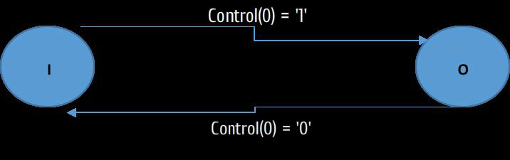
Although the implementation is surprisingly tricky at first, the basic operations of the circuit are not terribly complicated. The circuit has two modes of operation: when bit 0 of Control is a 0, the board is input mode and is to record a message; when bit 0 of Control is a 1, the board is to output a message. Within these modes are other operations dictated by bits 1 and 2 of Control: setting bit 1 to a 1 while in input mode stores a character, setting bit 1 to a 1 while in output mode cycles to the next screen, and setting bit 2 to a 1 resets the circuit and clears any stored message.
Starting the Code
To start the VHDL code you need to make a series of definitions. These definitions can be taken straight from the black box diagram. This is where the black box diagram proves most useful. The format for these definitions is as follows:
entity MartianMessageReader is
Port ( MessageIn : in STD_LOGIC_VECTOR (4 downto 0); -- character input
Control : in STD_LOGIC_VECTOR (2 downto 0); -- specifies state
ClockIn : in STD_LOGIC; -- the clock signal is the breath of the circuit
AnodeOut : out STD_LOGIC_VECTOR (3 downto 0); -- 7-seg disp output
CathodeOut : out STD_LOGIC_VECTOR (6 downto 0); -- 7-seg disp output
MessageStored : out std_logic; -- LED
MessageFull : out std_logic; -- LED
PossibleChange : out std_logic); -- LED
end MartianMessageReader;
If you scroll back up to the black box diagram, you can see that they are exactly the same.
Clock Signal
The clock signal is probably the most important part of the entire thing. The clock signal allows for the 7 Segment Display to work without flickering or operating too fast for any output to be seen by our slow human eyes. The Basys3 Board has a built-in clock signal which operates at 100MHz. This is far too fast for the 7 segment display, resulting in outputs even stranger than the Martians. To solve this problem a clock divider is necessary to specify the operating frequency.
ClockDiv : process (ClockIn) is
variable count : unsigned (17 downto 0) := "000000000000000000";
begin
if (rising_edge(ClockIn)) then
count := count + 1;
if (count = "110000110101000000") then
count := "000000000000000000";
Clock1 <= not Clock1;
end if;
end if;
end process ClockDiv;
GovernClock : process (ClockIn) is
variable count : unsigned (26 downto 0) := "000000000000000000000000000";
begin
if (rising_edge(ClockIn)) then
count := count + 1;
if (count = "101111101011110000100000000") then
count := "000000000000000000000000000";
ClockGovernor <= not ClockGovernor;
end if;
end if;
end process GovernClock;
As you can see above, there are two clock divider processes running. The purpose of the first clock divider is specifying the frequency of the 7-segment display; the second clock divider serves still a more fundamental purpose. To keep the storage variables stable, we need to make sure VHDL synthesizes the design with memory superior to latches; we accomplish this by placing all the logic in the main process under an if (rising_edge) statement so that a change can only occur on the pulse of the clock. The second clock divider sets the frequency of this clock at a manageable level. The rising edge of the clock is synchronized with the PossibleChange LED so that the user can set the character input as desired and then change the control inputs between LED pulses: when the LED flashes, the user knows the change was recorded, and can change the control inputs accordingly before the next rising edge.
Input If Block
The entire process needs to be governed by a clock. As discussed in the previous section, the use of a clock regulating the whole thing is necessary to ensure stability of the data. With everything under an if (rising_edge) statement, VHDL synthesizes everything correctly and all is grand. Following is the logic for the input if block:
if (rising_edge(ClockGovernor)) then
if (control(0) = '0' and control(1) = '1' and inputindex < 10) then -- board is in input mode & ready to store & is currently storing fewer than the maximum in the array of screens
ScreenStorage(inputindex)(lettercount) := MessageIn;
lettercount := lettercount + 1;
MessageStored <= '1';
if (lettercount = 1) then screencount := screencount + 1;
end if;
if (lettercount = 4) then
inputindex := inputindex + 1;
lettercount := 0;
if (inputindex = 10) then MessageFull <= '1';
end if;
end if;
end if;
As you can see, the input logic consists of a series of nested ifs; the ifs ensure that input only happens when 1) Control is in the right configuration and 2) the message is not full. The board stores the message one character at a time in a 2-d array (discussed shortly).
Output If Block
The second block of ifs handles the output. The board takes the stored message and passes it to the 7-segment display driver via the internal signal CharCode. It is crucial that the if loops related to the output process be under the same if(rising_edge(Clock)) as the input if loops. This ensures that everything occurs on the rising edge and we avoid mysterious, nasty timing issues.
Here is the code:
if (control(0) = '1') then -- output mode
if (outputindex = screencount) then outputindex := 0;
end if;
CharCode(19 downto 15) <= ScreenStorage(outputindex)(0);
CharCode(14 downto 10) <= ScreenStorage(outputindex)(1);
CharCode(9 downto 5) <= ScreenStorage(outputindex)(2);
CharCode(4 downto 0) <= ScreenStorage(outputindex)(3);
if (control(1) = '1') then outputindex := outputindex + 1;
end if;
end if;
The internal signal CharCode is wired up to the 7-segment display driver; the driver expects a single input corresponding to each screen of 4 characters of output it is to display. The way we have implemented it, each of the 4 characters is represented as 5 bits of the CharCode signal; hence, the CharCode signal is a concatenation of all 4 numbers representing a complete screen of output. The board displays the output one screen at a time, cycling through screens while bit 1 of control is high.
Defining the 7 Segment Display Driver
The 7 segment display driver must be implemented as a component which must be defined in the structural portion of the code. Following is the definition for the 7-segment display.
component SevenSegmentDisplayDriver
port ( CharNumber : in std_logic_vector(19 downto 0);
Clock7 : in std_logic;
AnodeBus : out ST.lpD_LOGIC_VECTOR(3 downto 0);
CathodeBus : out std_logic_vector(6 downto 0));
end component;
The component definition is out of the way; the next important step is defining the subparts. Here is where you need to make the connection between the top level module and the subparts. In the case only one subpart is needed. Following is the syntax to define the subpart.
SevSegDisp: SevenSegmentDisplayDriver port map (CharNumber => CharCode, Clock7 => Clock1, AnodeBus => AnodeOut, CathodeBus => CathodeOut);
7 Segment Display

Here is where things can differ depending on what exactly you want to be displayed on the display. As noted in the picture above each segment is represented a bit in a seven bit bus. Now it is your responsibility to code the relevant combinations, depending on the application. We are storing and displaying character strung together in words or phrases; we decided to display a code corresponding to a letter of the alphabet, or nothing for a space. 0-9 is A-E; a - f correspond to F-K; past that we displayed the letter itself if convenient, and a special character if not. Everything is one-to-one, and anyone with access to the code could decode the message. Following is the code to drive the display:
begin
process (Clock7) is
variable digit : unsigned (1 downto 0) := "00";
begin
if (rising_edge(Clock7)) then
if (digit = "00") then
AnodeBus <= "0111";
case CharNumber(19 downto 15) is
when "00000" => CathodeBus <= "1000000";
when "00001" => CathodeBus <= "1111001";
when "00010" => CathodeBus <= "0100100";
when "00011" => CathodeBus <= "0110000";
when "00100" => CathodeBus <= "0011001";
when "00101" => CathodeBus <= "0010010";
when "00110" => CathodeBus <= "0000010";
when "00111" => CathodeBus <= "1111000";
when "01000" => CathodeBus <= "0000000";
when "01001" => CathodeBus <= "0010000";
when "01010" => CathodeBus <= "0001000";
when "01011" => CathodeBus <= "0000011";
when "01100" => CathodeBus <= "1000110";
when "01101" => CathodeBus <= "0100001";
when "01110" => CathodeBus <= "0000110";
when "01111" => CathodeBus <= "0001110";
when "10000" => CathodeBus <= "0110110";
when "10001" => CathodeBus <= "0001001";
when "10010" => CathodeBus <= "0011011";
when "10011" => CathodeBus <= "1110001";
when "10100" => CathodeBus <= "1000111";
when "10101" => CathodeBus <= "1001000";
when "10110" => CathodeBus <= "0001100";
when "10111" => CathodeBus <= "1000001";
when "11000" => CathodeBus <= "0101101";
when "11001" => CathodeBus <= "1100100";
when others => CathodeBus <= "1111111";
end case;
elsif (digit = "01") then
AnodeBus <= "1011";
case CharNumber(14 downto 10) is
when "00000" => CathodeBus <= "1000000";
when "00001" => CathodeBus <= "1111001";
when "00010" => CathodeBus <= "0100100";
when "00011" => CathodeBus <= "0110000";
when "00100" => CathodeBus <= "0011001";
when "00101" => CathodeBus <= "0010010";
when "00110" => CathodeBus <= "0000010";
when "00111" => CathodeBus <= "1111000";
when "01000" => CathodeBus <= "0000000";
when "01001" => CathodeBus <= "0010000";
when "01010" => CathodeBus <= "0001000";
when "01011" => CathodeBus <= "0000011";
when "01100" => CathodeBus <= "1000110";
when "01101" => CathodeBus <= "0100001";
when "01110" => CathodeBus <= "0000110";
when "01111" => CathodeBus <= "0001110";
when "10000" => CathodeBus <= "0110110";
when "10001" => CathodeBus <= "0001001";
when "10010" => CathodeBus <= "0011011";
when "10011" => CathodeBus <= "1110001";
when "10100" => CathodeBus <= "1000111";
when "10101" => CathodeBus <= "1001000";
when "10110" => CathodeBus <= "0001100";
when "10111" => CathodeBus <= "1000001";
when "11000" => CathodeBus <= "0101101";
when "11001" => CathodeBus <= "1100100";
when others => CathodeBus <= "1111111";
end case;
elsif (digit = "10") then
AnodeBus <= "1101";
case CharNumber(9 downto 5) is
when "00000" => CathodeBus <= "1000000";
when "00001" => CathodeBus <= "1111001";
when "00010" => CathodeBus <= "0100100";
when "00011" => CathodeBus <= "0110000";
when "00100" => CathodeBus <= "0011001";
when "00101" => CathodeBus <= "0010010";
when "00110" => CathodeBus <= "0000010";
when "00111" => CathodeBus <= "1111000";
when "01000" => CathodeBus <= "0000000";
when "01001" => CathodeBus <= "0010000";
when "01010" => CathodeBus <= "0001000";
when "01011" => CathodeBus <= "0000011";
when "01100" => CathodeBus <= "1000110";
when "01101" => CathodeBus <= "0100001";
when "01110" => CathodeBus <= "0000110";
when "01111" => CathodeBus <= "0001110";
when "10000" => CathodeBus <= "0110110";
when "10001" => CathodeBus <= "0001001";
when "10010" => CathodeBus <= "0011011";
when "10011" => CathodeBus <= "1110001";
when "10100" => CathodeBus <= "1000111";
when "10101" => CathodeBus <= "1001000";
when "10110" => CathodeBus <= "0001100";
when "10111" => CathodeBus <= "1000001";
when "11000" => CathodeBus <= "0101101";
when "11001" => CathodeBus <= "1100100";
when others => CathodeBus <= "1111111";
end case;
elsif (digit = "11") then
AnodeBus <= "1110";
case CharNumber(4 downto 0) is
when "00000" => CathodeBus <= "1000000";
when "00001" => CathodeBus <= "1111001";
when "00010" => CathodeBus <= "0100100";
when "00011" => CathodeBus <= "0110000";
when "00100" => CathodeBus <= "0011001";
when "00101" => CathodeBus <= "0010010";
when "00110" => CathodeBus <= "0000010";
when "00111" => CathodeBus <= "1111000";
when "01000" => CathodeBus <= "0000000";
when "01001" => CathodeBus <= "0010000";
when "01010" => CathodeBus <= "0001000";
when "01011" => CathodeBus <= "0000011";
when "01100" => CathodeBus <= "1000110";
when "01101" => CathodeBus <= "0100001";
when "01110" => CathodeBus <= "0000110";
when "01111" => CathodeBus <= "0001110";
when "10000" => CathodeBus <= "0110110";
when "10001" => CathodeBus <= "0001001";
when "10010" => CathodeBus <= "0011011";
when "10011" => CathodeBus <= "1110001";
when "10100" => CathodeBus <= "1000111";
when "10101" => CathodeBus <= "1001000";
when "10110" => CathodeBus <= "0001100";
when "10111" => CathodeBus <= "1000001";
when "11000" => CathodeBus <= "0101101";
when "11001" => CathodeBus <= "1100100";
when others => CathodeBus <= "1111111";
end case;
end if;
digit := digit + 1;
end if;
end process;
end Behavioral;
Schematic

This is the schematic of the Martian Message Reader. In other words, this is the actual hardware that VHDL synthesized to give us the behavior described by our code. Intense, to say the least. We now know that this problem can be solved structurally with fiftyeleven muxes, comparators, and registers. Thanks to behavioral code, we do not need to spend the rest of our lives wiring them up.
Entire Code
We have broken down the code behind a Martian Message reader into its parts. Here is the whole code in all its glory:
library IEEE;
use IEEE.STD_LOGIC_1164.ALL;
use IEEE.NUMERIC_STD.ALL;
entity MartianMessageReader is
Port ( MessageIn : in STD_LOGIC_VECTOR (4 downto 0);
Control : in STD_LOGIC_VECTOR (2 downto 0);
ClockIn : in STD_LOGIC;
AnodeOut : out STD_LOGIC_VECTOR (3 downto 0);
CathodeOut : out STD_LOGIC_VECTOR (6 downto 0);
MessageStored : out std_logic;
MessageFull : out std_logic;
PossibleChange : out std_logic);
end MartianMessageReader;
architecture Behavioral of MartianMessageReader is
component SevenSegmentDisplayDriver port ( CharNumber : in std_logic_vector(19 downto 0);
Clock7 : in std_logic;
AnodeBus : out ST.lpD_LOGIC_VECTOR(3 downto 0);
CathodeBus : out std_logic_vector(6 downto 0));
end component;
type LetterArray is array (3 downto 0) of std_logic_vector(4 downto 0);
type ScreenArray is array (9 downto 0) of LetterArray; -- The message is stored as an array of arrays of -- vectors; each 5-bit vectorrepresents 1 character
signal CharCode : std_logic_vector(19 downto 0) := "11111111111111111111" ; --this is the input to the 7- --segment display driver. We --initialize it to start off holding --all spaces, or nothing
signal Clock1 : std_logic := '0'; -- clock for the 7-segment display
signal ClockGovernor : std_logic := '0'; -- clock to run the whole show
begin
SevSegDisp: SevenSegmentDisplayDriver port map (CharNumber => CharCode, Clock7 => Clock1, AnodeBus => AnodeOut, CathodeBus => CathodeOut);
PossibleChange <= ClockGovernor;
ClockDiv : process (ClockIn) is
variable count : unsigned (17 downto 0) := "000000000000000000";
begin
if (rising_edge(ClockIn)) then
count := count + 1;
if (count = "110000110101000000") then count := "000000000000000000";
Clock1 <= not Clock1;
end if;
end if;
end process ClockDiv;
GovernClock : process (ClockIn) is
variable count : unsigned (26 downto 0) := "000000000000000000000000000";
begin
if (rising_edge(ClockIn)) then
count := count + 1;
if (count = "101111101011110000100000000") then count := "000000000000000000000000000";
ClockGovernor <= not ClockGovernor;
end if;
end if;
end process GovernClock;
EmergencyInfoStorageSystem : process(control, ClockGovernor) is
variable ScreenStorage : ScreenArray := (others => (others => "11111")); -- initialize array to hold all spaces; --it's important to initialize --EVERYTHING so there are no --surprises
variable lettercount : integer := 0;
variable screencount : integer := 0;
variable inputindex : integer := 0;
variable outputindex : integer := 0;
begin
if (rising_edge(ClockGovernor)) then
if (control(0) = '0' and control(1) = '1' and inputindex < 10) then -- board is in input mode & ready to store -- & is currently storing fewer than the -- maximum in the array of screens
ScreenStorage(inputindex)(lettercount) := MessageIn;
lettercount := lettercount + 1;
MessageStored <= '1';
if (lettercount = 1) then screencount := screencount + 1;
end if;
if (lettercount = 4) then
inputindex := inputindex + 1;
lettercount := 0;
if (inputindex = 10) then MessageFull <= '1';
end if;
end if;
end if;
if (control(0) = '1') then -- output mode
if (outputindex = screencount) then outputindex := 0;
end if;
CharCode(19 downto 15) <= ScreenStorage(outputindex)(0);
CharCode(14 downto 10) <= ScreenStorage(outputindex)(1);
CharCode(9 downto 5) <= ScreenStorage(outputindex)(2);
CharCode(4 downto 0) <= ScreenStorage(outputindex)(3);
if (control(1) = '1') then outputindex := outputindex + 1;
end if;
end if;
if (control(2) = '1') then -- reset mechanism
MessageStored <= '0';
MessageFull <= '0';
lettercount := 0;
screencount := 0;
inputindex := 0;
outputindex := 0;
ScreenStorage := (others => (others => "11111"));
CharCode <= "11111111111111111111";
end if;
end if;
end process EmergencyInfoStorageSystem;
end Behavioral;
SUBPART:
library IEEE;
use IEEE.STD_LOGIC_1164.ALL;
use IEEE.NUMERIC_STD.ALL;
entity SevenSegmentDisplayDriver is
Port ( CharNumber : in STD_LOGIC_VECTOR (19 downto 0);
Clock7 : in STD_LOGIC;
AnodeBus : out STD_LOGIC_VECTOR (3 downto 0);
CathodeBus : out STD_LOGIC_VECTOR (6 downto 0));
end SevenSegmentDisplayDriver;
architecture Behavioral of SevenSegmentDisplayDriver is
begin
process (Clocbegin
process (Clock7) is
variable digit : unsigned (1 downto 0) := "00";
begin
if (rising_edge(Clock7)) then
if (digit = "00") then
AnodeBus <= "0111";
case CharNumber(19 downto 15) is
when "00000" => CathodeBus <= "1000000";
when "00001" => CathodeBus <= "1111001";
when "00010" => CathodeBus <= "0100100";
when "00011" => CathodeBus <= "0110000";
when "00100" => CathodeBus <= "0011001";
when "00101" => CathodeBus <= "0010010";
when "00110" => CathodeBus <= "0000010";
when "00111" => CathodeBus <= "1111000";
when "01000" => CathodeBus <= "0000000";
when "01001" => CathodeBus <= "0010000";
when "01010" => CathodeBus <= "0001000";
when "01011" => CathodeBus <= "0000011";
when "01100" => CathodeBus <= "1000110";
when "01101" => CathodeBus <= "0100001";
when "01110" => CathodeBus <= "0000110";
when "01111" => CathodeBus <= "0001110";
when "10000" => CathodeBus <= "0110110";
when "10001" => CathodeBus <= "0001001";
when "10010" => CathodeBus <= "0011011";
when "10011" => CathodeBus <= "1110001";
when "10100" => CathodeBus <= "1000111";
when "10101" => CathodeBus <= "1001000";
when "10110" => CathodeBus <= "0001100";
when "10111" => CathodeBus <= "1000001";
when "11000" => CathodeBus <= "0101101";
when "11001" => CathodeBus <= "1100100";
when others => CathodeBus <= "1111111";
end case;
elsif (digit = "01") then
AnodeBus <= "1011";
case CharNumber(14 downto 10) is
when "00000" => CathodeBus <= "1000000";
when "00001" => CathodeBus <= "1111001";
when "00010" => CathodeBus <= "0100100";
when "00011" => CathodeBus <= "0110000";
when "00100" => CathodeBus <= "0011001";
when "00101" => CathodeBus <= "0010010";
when "00110" => CathodeBus <= "0000010";
when "00111" => CathodeBus <= "1111000";
when "01000" => CathodeBus <= "0000000";
when "01001" => CathodeBus <= "0010000";
when "01010" => CathodeBus <= "0001000";
when "01011" => CathodeBus <= "0000011";
when "01100" => CathodeBus <= "1000110";
when "01101" => CathodeBus <= "0100001";
when "01110" => CathodeBus <= "0000110";
when "01111" => CathodeBus <= "0001110";
when "10000" => CathodeBus <= "0110110";
when "10001" => CathodeBus <= "0001001";
when "10010" => CathodeBus <= "0011011";
when "10011" => CathodeBus <= "1110001";
when "10100" => CathodeBus <= "1000111";
when "10101" => CathodeBus <= "1001000";
when "10110" => CathodeBus <= "0001100";
when "10111" => CathodeBus <= "1000001";
when "11000" => CathodeBus <= "0101101";
when "11001" => CathodeBus <= "1100100";
when others => CathodeBus <= "1111111";
end case;
elsif (digit = "10") then
AnodeBus <= "1101";
case CharNumber(9 downto 5) is
when "00000" => CathodeBus <= "1000000";
when "00001" => CathodeBus <= "1111001";
when "00010" => CathodeBus <= "0100100";
when "00011" => CathodeBus <= "0110000";
when "00100" => CathodeBus <= "0011001";
when "00101" => CathodeBus <= "0010010";
when "00110" => CathodeBus <= "0000010";
when "00111" => CathodeBus <= "1111000";
when "01000" => CathodeBus <= "0000000";
when "01001" => CathodeBus <= "0010000";
when "01010" => CathodeBus <= "0001000";
when "01011" => CathodeBus <= "0000011";
when "01100" => CathodeBus <= "1000110";
when "01101" => CathodeBus <= "0100001";
when "01110" => CathodeBus <= "0000110";
when "01111" => CathodeBus <= "0001110";
when "10000" => CathodeBus <= "0110110";
when "10001" => CathodeBus <= "0001001";
when "10010" => CathodeBus <= "0011011";
when "10011" => CathodeBus <= "1110001";
when "10100" => CathodeBus <= "1000111";
when "10101" => CathodeBus <= "1001000";
when "10110" => CathodeBus <= "0001100";
when "10111" => CathodeBus <= "1000001";
when "11000" => CathodeBus <= "0101101";
when "11001" => CathodeBus <= "1100100";
when others => CathodeBus <= "1111111";
end case;
elsif (digit = "11") then
AnodeBus <= "1110";
case CharNumber(4 downto 0) is
when "00000" => CathodeBus <= "1000000";
when "00001" => CathodeBus <= "1111001";
when "00010" => CathodeBus <= "0100100";
when "00011" => CathodeBus <= "0110000";
when "00100" => CathodeBus <= "0011001";
when "00101" => CathodeBus <= "0010010";
when "00110" => CathodeBus <= "0000010";
when "00111" => CathodeBus <= "1111000";
when "01000" => CathodeBus <= "0000000";
when "01001" => CathodeBus <= "0010000";
when "01010" => CathodeBus <= "0001000";
when "01011" => CathodeBus <= "0000011";
when "01100" => CathodeBus <= "1000110";
when "01101" => CathodeBus <= "0100001";
when "01110" => CathodeBus <= "0000110";
when "01111" => CathodeBus <= "0001110";
when "10000" => CathodeBus <= "0110110";
when "10001" => CathodeBus <= "0001001";
when "10010" => CathodeBus <= "0011011";
when "10011" => CathodeBus <= "1110001";
when "10100" => CathodeBus <= "1000111";
when "10101" => CathodeBus <= "1001000";
when "10110" => CathodeBus <= "0001100";
when "10111" => CathodeBus <= "1000001";
when "11000" => CathodeBus <= "0101101";
when "11001" => CathodeBus <= "1100100";
when others => CathodeBus <= "1111111";
end case;
end if;
digit := digit + 1;
end if;
end process;
end Behavioral;
Signals/Other Definitions
Signals are very helpful in VHDL coding because they allow you to connect various parts of the code together. For example if you were to have multiple process blocks, using signals would be very beneficial because those signals would structurally connect those process blocks together. Variables, on the other hand, can be manipulated within various process blocks. The interesting part about variables is that when you have multiple process blocks, you cannot use the same variable in multiple process blocks; their scope is always local. They're very useful for timing purposes since assignment happens immediately instead of at the end of the process. Finally, we need to define the array. An array is handy for storing and displaying the output since arrays are easy to cycle through with an index. Following is the code for those definitions.
type LetterArray is array (3 downto 0) of std_logic_vector(4 downto 0);
type ScreenArray is array (9 downto 0) of LetterArray;
signal CharCode : std_logic_vector(19 downto 0) := "11111111111111111111" ;
signal Clock1 : std_logic := '0';
signal ClockGovernor : std_logic := '0';
VARIABLE DEFINITIONS ARE PLACED BEFORE THE PROCESS BLOCK
variable ScreenStorage : ScreenArray := (others => (others => "11111"));
variable lettercount : integer := 0;
variable screencount : integer := 0;
variable inputindex : integer := 0;
variable outputindex : integer := 0;