Marlin Based Bottle to Filament Machine
by tuenhidiy in Circuits > Arduino
9621 Views, 136 Favorites, 0 Comments
Marlin Based Bottle to Filament Machine


There are a lot of PET bottles filament maker projects on the Instructables and Youtube, and I wanted to make one like this as well. I made my own a bottle to filament machine without using 3D printed parts. So, check out my video and let’s get started.
Supplies

First of all, I would like to sincerely thank PCBWay for the sponsoring and supporting me on this project.

If you want to make the PCB, 3D printing & CNC machining for your project or buy high quality modules at low price, please visit the PCBWay website to get exciting discounts and coupons as follows:
⦾ Special Sales in PCBWay Store!
⦾ Full feature custom PCB prototype service.
⦾ Online 3D printing & CNC Machining service.
A. Main parts:
⦾ 1pcs x Arduino Mega 2560.
⦾ 1pcs x RAMPS 1.4 Controller. (Or RAMPS 1.6)
⦾ 1pcs x LCD 2004 including ribbon cables and PCB adapter for Ramps 1.4.
⦾ 2pcs x A4988 Stepper Driver Module. (Or 2pcs x DRV8825)
⦾ 2pcs x Stepper Motor NEMA 17.
⦾ 2pcs x GT2 Timing Pulley 16 Teeth.
⦾ 2pcs x GT2 Timing Pulley 60/80 Teeth.
⦾ 2pcs x GT2 6mm Closed Timing Belt 400mm.
⦾ 1pcs x Round Shaft Diameter 5mm, Length 150mm.
⦾ 1pcs x Round Shaft Diameter 8mm, Length 100mm.
⦾ 1pcs x Round Shaft Diameter 8mm, Length 200mm.
⦾ 5pcs x Ball Flanged Shielded Bearings 8 x 22 x 7mm.
⦾ 2pcs x Horizontal Bearings 8mm.
⦾ 2pcs x Ball Bearings 5mm.
⦾ 2pcs x V-Slot Aluminium Profile 2020, length 400mm.
⦾ 3pcs x V-Slot Aluminium Profile 2020, length 200mm.
⦾ 1pcs x V-Slot Aluminium Profile 2020, length 250mm.
⦾ 2pcs x V-Slot Aluminium Profile 2020, length 100mm.
⦾ 1pcs x Bowden Hotend. We used only its heat block, heater, thermistor and nozzle.
⦾ 1pcs x Power Supply PSU 12 VDC.
⦾ 1 meter x PTEF Teflon Tube, inner diameter 2mm and outer diameter 4mm.
⦾ 2 meters x Two cores Power Cable 1.5/2.5 mm2 for main power supply and heat bed.
⦾ 2 meters x Cable Spiral Wrap, small size.
⦾ 1 meter x Cabe Tray 20x20.
⦾ Aluminium/ Arcrylic/ Wood plate dimesion (W x L) 120 x 400mm.
⦾ Some empty filament spools, ballpoint pen's springs, knife blades,
B. PVC pipes and fittings:
⦾ 2pcs x PVC Connecting Pipe Ø49mm.
⦾ 2pcs x PVC End Cap Ø21mm.
⦾ 7pcs x PVC End Cap Ø42mm.
⦾ 1pcs x PVC End Cap Ø114mm.
C. Tools:
⦾ Drilling machine.
⦾ PVC pipe cutter.
⦾ Gas torch/ Lighter.
Build a Frame
I used 4pcs x 2020 aluminum profiles to form a rectangular base with outer dimension 400x240mm.

To make the frame sturdy, I fixed it with M6 bolts at the 4 corners.

Assembly a Filament Winder
This was the most difficult part for me to make this machine. As we know, each timing belt pulley 80-teeth (or 60-teeth) has 2 holes to tighten the set screws and they fits M5 or M4 bolts.

I drilled a big holes on the Ø42 PVC endcap, fastened the pulley to the PVC endcap. Then I measured and drilled 2 small holes on the side of end cap, corresponding to the positions of 2 holes on the pulley. Two bolts M4 (or M5) were tightened through a PVC fitting to the pulley holes. I made two similar ones like that.


I inserted these endcaps into both ends of a PVC connecting pipe Ø49. It fitted tightly and I glued them together with super glue 502.


A PVC connecting pipe Ø49 has outer diameter around 58mm. So I used empty filament spools that have inner hole diameters around 58mm. Then I wrapped a layer of tape on the PVC fitting to make sure they were tight before glueing them together.
The size of PVC fittings may vary by country, please take note this.


I made another one similar to this, with only 1 small filament spool for this project. My winder was driven by 2 steppers motors via GT2 6mm closed timing belts 400mm and pulley ratio 16:80.

Modify a Heat Block
I did a step-by-step drilling using drill bits in order #6, #7 and #8mm on the heat block.

One small steel bracket was drilled to fix the nozzle to machine base.

One worn-out nozzle was drilled about 1.6mm hole. To mount the hotend, I use one insulator to minimize heat transfer from bracket to aluminium profiles.

Assembly a Roller
Firstly I made a roller using PVC fittings, at both ends it had 2 bearings like this.

In the middle, this roller had a groove to guide the filament and it worked well.

Finally I found a steel roller, maybe it came from a belt misalignment switch. It is better choice for cooling down the PET filament, and it looks much stronger.

I mounted this roller on the aluminium profile by 2pcs x horizontal bearings.

Build a Filament Uncoiler
I also made an uncoiler using PVC fittings, one shaft 8mm with length 100 mm, and 3 bearings
The method was similar to the previous step, only 2pcs x endcaps were reversed when inserted them into the connecting pipe.

I can stack 2 filament rolls on it.

RAMPS 1.6 and LCD 2004
I had some aluminium plates from radiator and it was time to use them.

I mounted one power supply 12VDC/ 10A, Arduino Mega 2560 and LCD 2004 on it.

I fixed this aluminium plate to machine frame, did cabling and connection. All cables were covered by cable tray 20x20mm and spiral cable wraps.

Marlin Configuration
My PET bottle filament machine is based on Marlin firmware 2.1.2. I have configured as follows:
1/ Parameters setting in "Configuration.h"
⦾ Motherboard
// Choose the name from boards.h that matches your setup
#ifndef MOTHERBOARD
  #define MOTHERBOARD BOARD_RAMPS_14_EFB
#endif
⦾ Extruder
// This defines the number of extruders
// :[0, 1, 2, 3, 4, 5, 6, 7, 8]
#define EXTRUDERS 1
// Generally expected filament diameter (1.75, 2.85, 3.0, ...). Used for Volumetric, Filament Width Sensor, etc.
#define DEFAULT_NOMINAL_FILAMENT_DIA 1.75
⦾ Thermal Settings
#define TEMP_SENSOR_0 1
⦾ Stepper Drivers
#define E0_DRIVER_TYPE A4988
#define E1_DRIVER_TYPE A4988
⦾ Movement Settings
#define DEFAULT_AXIS_STEPS_PER_UNIT   { 100, 100, 400, 100}
#define DEFAULT_MAX_FEEDRATE          { 100, 100, 5, 25 }
For dual extruders, the step/mm was calculated as follow:

⦾ LCD and SD support
#define LCD_LANGUAGE en
#define DISPLAY_CHARSET_HD44780 JAPANESE
#define LCD_INFO_SCREEN_STYLE 0
#define SDSUPPORT
#define SD_CHECK_AND_RETRY
//  Set this option if CLOCKWISE causes values to DECREASE
#define REVERSE_ENCODER_DIRECTION
#define SPEAKER
⦾ LCD / Controller Selection
#define REPRAP_DISCOUNT_SMART_CONTROLLER
⦾ Disable "Cold extrusion prevented" and "Too long extrusion prevented"
//#define PREVENT_COLD_EXTRUSION
//#define EXTRUDE_MINTEMP 170
//#define PREVENT_LENGTHY_EXTRUDE
//#define EXTRUDE_MAXLENGTH 200
2/ Parameters setting in "Configuration_adv.h"
⦾ Dual Extruders
Since my winder - E axis was driven by two synchronized stepper motors and they were mounted opposites each other, so I uncommented parameters "E_DUAL_STEPPER_DRIVERS" and "INVERT_E1_VS_E0_DIR" for their direction signals.
#define E_DUAL_STEPPER_DRIVERS
#if ENABLED(E_DUAL_STEPPER_DRIVERS)
  #define INVERT_E1_VS_E0_DIR       // E direction signals are opposites
#endif
⦾ Extruder feedrate when moving on the LCD
#define MANUAL_FEEDRATE { 50*60, 50*60, 4*60, 2*60 } // (mm/min) Feedrates for manual moves along X, Y, Z, E from panel
Take note the E manual feedrate "2*60" (mm/min), when we move the E axis on the LCD, the controller will apply this parameter.
Filament Runout Sensor
With the configuration in the previous step, I was able to run the machine in manual mode but I wanted to run machine using GCODE from the SD card. Of course, in this case, I can use "Pause/ Resume" or "Change Filament" on the LCD screen to change the bottle strip. But I like the use of a push button to simulate breaking or running out of filament.


RAMPS 1.6 use SERVO3_PIN for the first filament runout sensor. I connected a push button's NO contact to pin D4 and GND as shown in the picture below.

Filament runout sensor was configure in the Marlin as follow:
⦾ In the "Configuration.h"
When I press push button, pin D4 turn "LOW" indicating that filament is NOT present and call M600 to initiates the filament change procedure.
#define FILAMENT_RUNOUT_SENSOR
#if ENABLED(FILAMENT_RUNOUT_SENSOR)
  #define FIL_RUNOUT_ENABLED_DEFAULT true // Enable the sensor on startup. Override with M412 followed by M500.
  #define NUM_RUNOUT_SENSORS   1          // Number of sensors, up to one per extruder. Define a FIL_RUNOUT#_PIN for each.


  #define FIL_RUNOUT_STATE     LOW        // Pin state indicating that filament is NOT present.
  #define FIL_RUNOUT_PULLUP               // Use internal pullup for filament runout pins.

  #define FILAMENT_RUNOUT_SCRIPT "M600 T0"
Enable NOZZLE_PARK_FEATURE
#define NOZZLE_PARK_FEATURE
⦾ In the "Configuration_adv.h"
Enable ADVANCED_PAUSE_FEATURE
#define ADVANCED_PAUSE_FEATURE
There a lot of menu options to change, unload and load filament that we can tweak for our machine, for example: Setting the winder to a slower initial feedrate after we joint the bottle strip to winder's pulling rope and then, when this connection position reaches to roller or winder, the machine will switch to a faster working feedrate.
We can check the filament runout pin status with M119.
M119
Reporting endstop status
x_min: open
y_min: open
z_min: open
filament: TRIGGERED
My machine looks like this finally.

Gcode
My winder operates in "Extruder Relative Mode", we can set by GCODE with 2 following options:
⦾ Relative Mode (G91): all coordinates are interpreted as relative, adding onto the previous position.
⦾ Extruder Relative Mode (M83): the E coordinate is interpreted as relative, adding onto the previous E position. This command is used to override G90 and put the E axis into relative mode independent of the other axes.
Based on the estimated bottle strip length, I divided Extruder's moves into small segments, 1mm or 2mm, and copied out a few thousand same lines of code. The goal is to pause my machine by push button once it completes its last movement, initiate the bottle strip change procedure then resume the machine again.
I made my own two Gcode templates as follows:
⦾ GCode with temperature:
M104 S220 ;Set target temperature for the active hotend
M105 ;Get a temperature report
M109 S220 ;Wait for Hotend Temperature
M83 ;Relative extrusion mode
G92 E0 ;Reset Extruder
G1 E2 F120
..........
..........
..........
G1 E2 F120
M104 S0 ;Set target temperature for the active hotend
M84 E ;Disable E steppers
⦾ GCode with no (manual) temperature: I set and adjusted the temperature manually via the LCD screen.
M302 P1 ;Disable cold extrusion checking
M83 ;Relative extrusion mode
G92 E0 ;Reset Extruder
G1 E2 F120
..........
..........
..........
G1 E2 F120
M84 E ;Disable E steppers
By this way, I can create Gcode templates for many different types of bottles after some testings, which can mainly vary in feedrate and temperature. Or I can modify via "Tune" menu for adjusting the temperature and feedrate during running the machine from SD Card.
Bottle Cutter
I made a simple but effective bottle cutter for bottles smaller than 110mm in diameter. It was made up of two PVC endcaps Ø114 and Ø42mm. I cut small slits on the encaps' side with 8mm and 12mm high, compared to the bottom.


I fixed the small endcap to the big endcap with M5 bolt. The small one can be rotated around M5 bolt to adjust the gap. I also drilled 3 holes on the big endcap, corresponding to my fingers for easier holding.

It works well even with bottles that have ribs like this.

I also made another version of bottle cutter using aluminum profile 2020 and PVC fittings. It worked very well too.


It's easier to hold and had a 4mm round bar.

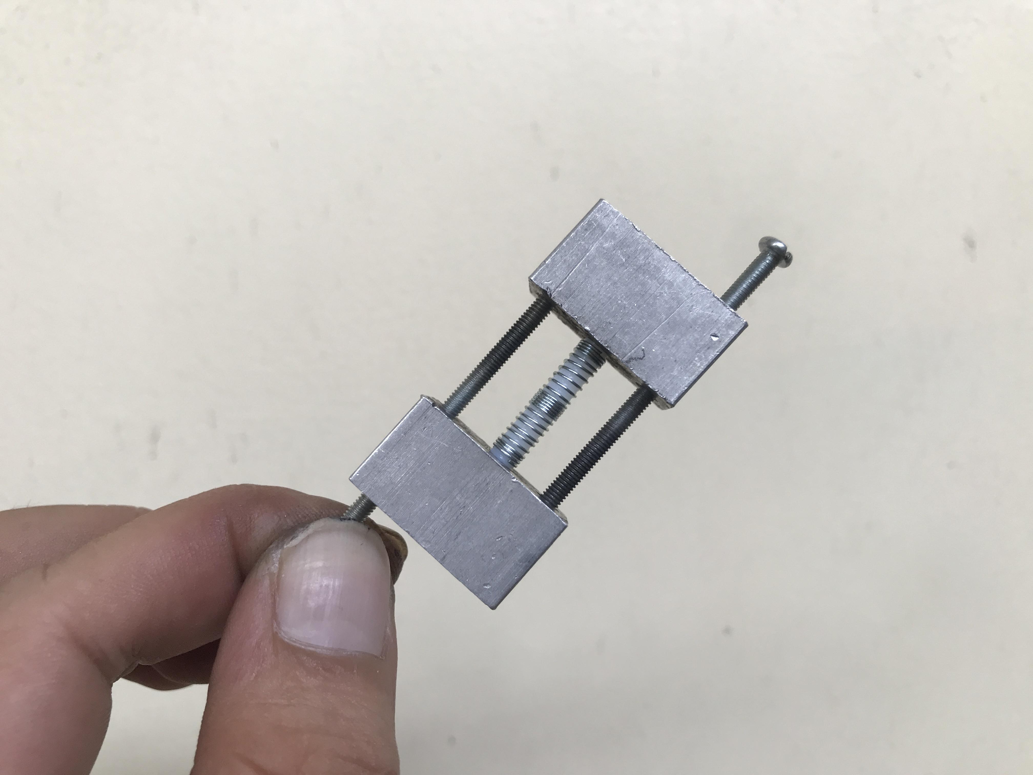
PET Filament Welding Tool
It was interesting when I made this tool. First I made the external threads on the PTEF teflon tube Ø4mm, using the spring that was taken from a ballpoint pen and rotated it into the threads.


I used 2 aluminum pieces and 2 bolts to fix the teflon tube. The teflon tube was also tightened to the aluminum piece through the M4 threaded hole. It worked well but I used a lighter so it heated slowly because the aluminum dissipated the heat. I believe it works great with a gas torch.

Finally I made this one, it's very simple, compact but worked really effective. It consists of:
⦾ An external threaded tefton tube,
⦾ Two ballpoint springs that are tightly compressed with a length equal to a lighter width 10 ~12mm. The density of spring turns is concentrated in the middle.
⦾ And two M4 nuts for holding the springs at both ends.
While heating the spring, I can hold a long teflon tip and spin it around. It's not hot enough at this moment, it's getting hot when we push the filament out.


After welding, we should use a plier to hold the M4 nut one side and push the PET filament to the opposite side. Remember to place the PET filament output facing to the ground otherwise it may fold due to gravity.

Testing
After downloading Marlin firmware to Arduino Mega 2560, I powered on and tested the winder movement first. I had to unscrewed the pulleys from two stepper motor shafts just to be safe.

From LCD screen, I checked "Runout Sensor" state and turn "ON" if it off.

I also checked the filament runout sensor status with M119 by pressing and releasing the button.

When a push button is pressed while the machine is running, the bottle strip change process takes place in the order below.

I used "filament purge" function in the "ADVANCED_PAUSE_FEATURE" to run the machine when I joined the bottle strip to winder's pulling rope. The purging feedrate and length at this time can be adjusted, as follow:
  #define ADVANCED_PAUSE_PURGE_FEEDRATE        2  // (mm/s) Extrude feedrate (after loading). Should be slower than load feedrate.
  #define ADVANCED_PAUSE_PURGE_LENGTH         50  // (mm) Length to extrude after loading.
The "Tune" menu is available on the LCD while the machine runs GCode from the SD Card. And Speed (Feedrate multiplier) and Nozzle (Nozzle temperature) items can be adjusted.

Below picture shows the PET filament output.


Improvement
I think this machine can be improved according to the following ideas:
⦾ Mounting a bottle cutter and real filament run-out sensor to the machine line.
⦾ Customize the LCD display, for example enable "CUSTOM_USER_MENUS" in Marlin and add some functions.
⦾ We can configure the power outputs for Hotend0, Hotend1, Fan/Bed on RAMPS 1.4 (or RAMPS 1.6) based on "Marlin-2.1.2\Marlin\src\core\boards.h"
#define BOARD_RAMPS_14_EFB            1020  // RAMPS 1.4 (Power outputs: Hotend, Fan, Bed)
#define BOARD_RAMPS_14_EEB            1021  // RAMPS 1.4 (Power outputs: Hotend0, Hotend1, Bed)
#define BOARD_RAMPS_14_EFF            1022  // RAMPS 1.4 (Power outputs: Hotend, Fan0, Fan1)
#define BOARD_RAMPS_14_EEF            1023  // RAMPS 1.4 (Power outputs: Hotend0, Hotend1, Fan)
#define BOARD_RAMPS_14_SF             1024  // RAMPS 1.4 (Power outputs: Spindle, Controller Fan)
These suffixed board names determine the Extruder / Bed / Fan assignments, for examples: _EEB stand for Extruder/ Extruder/ Bed at the power output terminals. I means with this machine I can extend to 2/3 hotends working at the same time, just simply mounting them on 2020 aluminium profile and my winder have enough space and strength to roll them. On the other hand, RAMPS 1.6 still has 3 unused stepper motors.
Conclusion


I am always impressed with projects that contribute significantly to environmental initiatives. I haven't collected enough plastic bottles to test print, but I'm sure it can be done because many people have done it sucessfully.
Thank you for reading my works!!!