Marblevator Baby Steps Revisited
by gzumwalt in Workshop > 3D Printing
4781 Views, 37 Favorites, 0 Comments
Marblevator Baby Steps Revisited
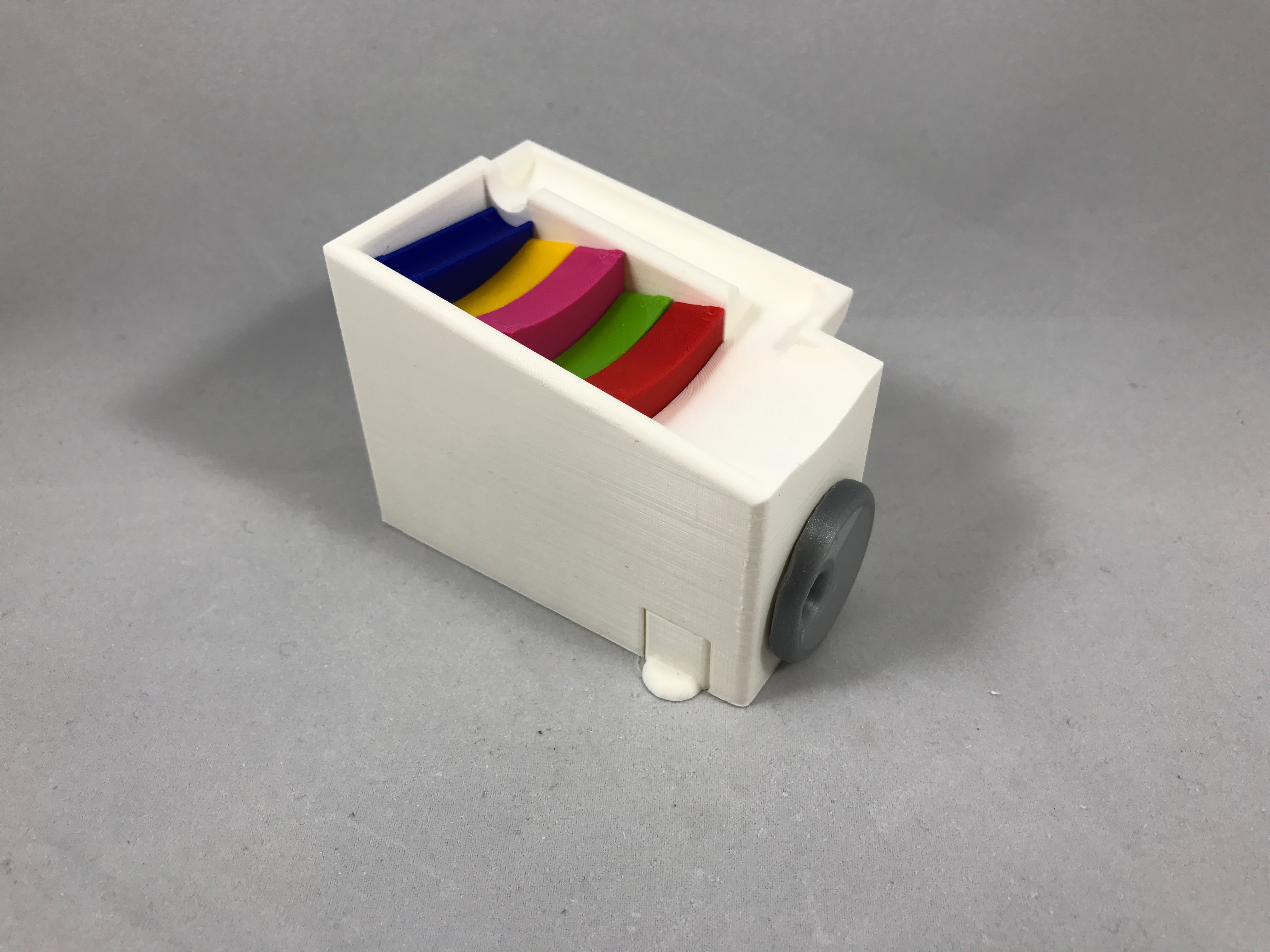
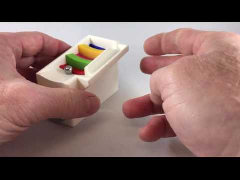
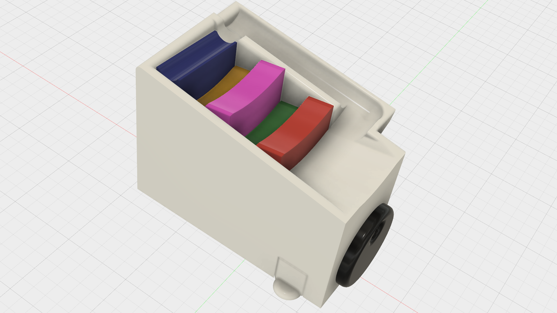
Marblevator Baby Steps Revisited is an improved design of my previous Marblevator Baby steps.
One of the improvements is that the stair steps ("Step 1.stl" through "Step 5.stl") no longer fall out when Marblevator Baby Steps Revisited is turned upside down (this improvement is thanks to grandkids and "how does it work" enthusiasts). Another is a small compartment designed to contain the "marbles" when not in use. Finally, the surfaces are smoother and more continuous than the previous design thanks to some of the design tools available in Autodesk Fusion 360.
The design features two operating knobs, one in the front and one in the rear. Either knob can be rotated in either direction to operate Marblevator Baby Steps Revisited, so it is easy for left and right handers to operate.
You will need to purchase at least one 8mm (5/16") diameter ball bearing to use as the marble.
I probably forgot a file or two or something, so if you have any questions, please feel free to ask.
Designed using Autodesk Fusion 360, sliced using Cura 2.3.1, and printed on both an Ultimaker 2+ Extended and an Ultimaker 3 Extended.
Print and Prepare the Parts.
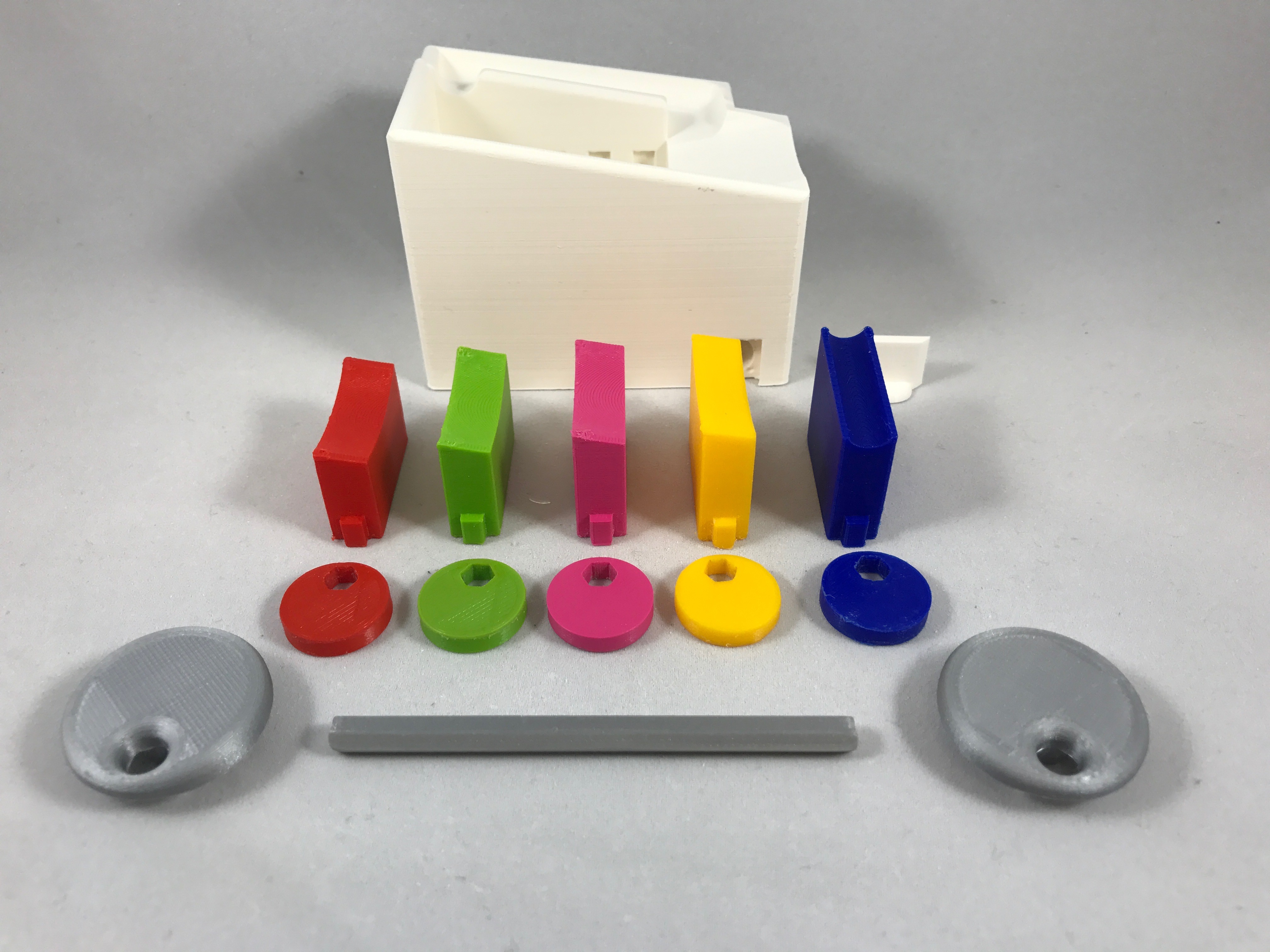
I printed my parts on an Ultimaker 2+ Extended and an Ultimaker 3 Extended using .1mm vertical resolution and 20% infill.
Print two "Knob.stl" and five "Cam Lobe.stl", and one each of the remaining parts.
Printing "Base.stl" with supports is optional. I printed one base with supports, and a second base without. With some cleanup, both worked fine.
Prior to assembly, test fit and trim, file, sand, etc. all parts as necessary for smooth movement of moving surfaces, and tight fit for non moving surfaces. Depending on the colors you chose and your printer settings, more or less trimming, filing and/or sanding may be required.
Carefully file all edges that contacted the build plate to make absolutely sure that all build plate "ooze" is removed and that all edges are smooth. I used a flat jewelers file and plenty of patience to perform this step.
Install the Steps.
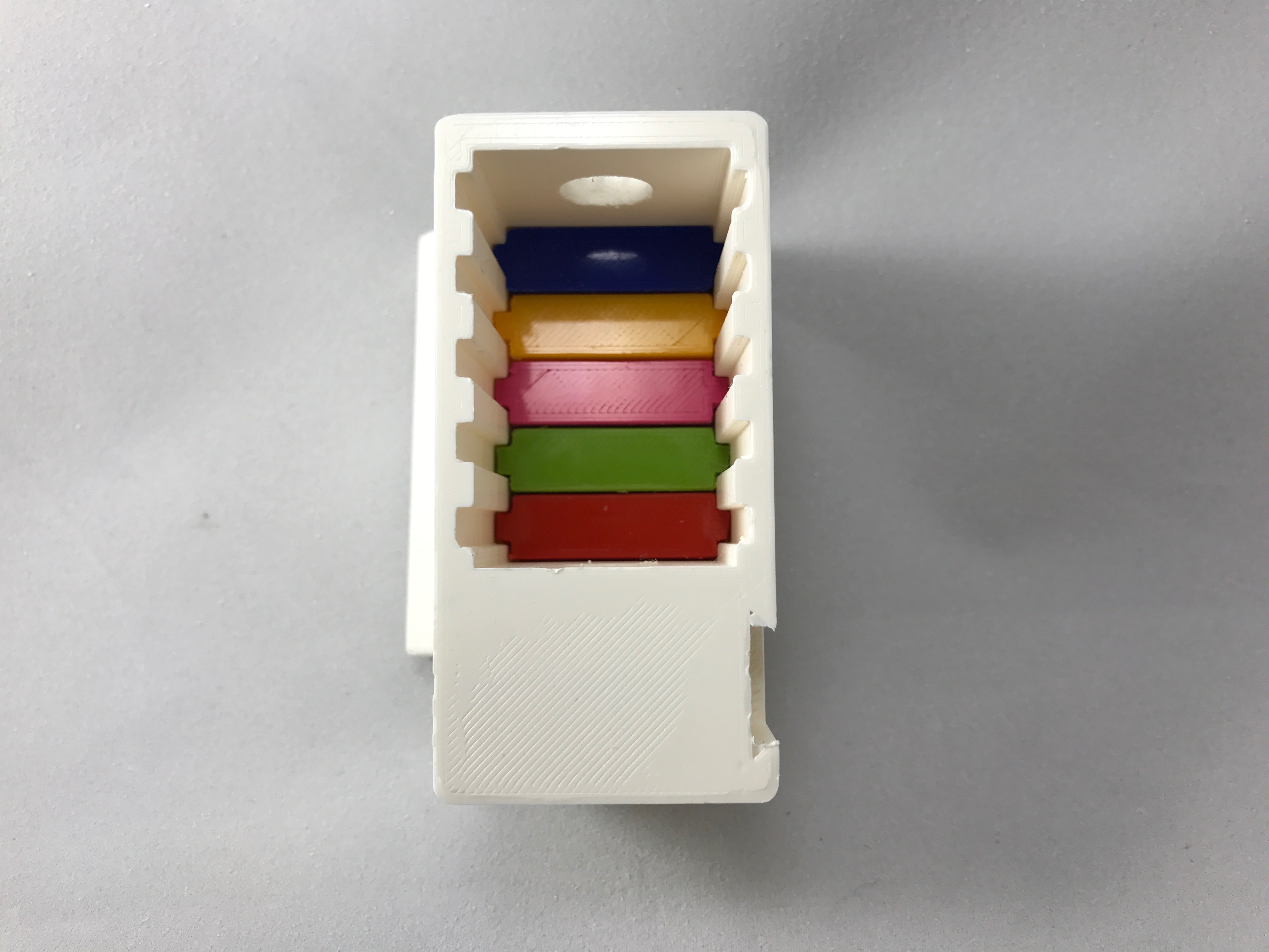
Slide each of the five steps into the respective guide slot in the bottom of "Base.stl", making certain that each step faces the correct direction and is in the correct position. "Step 1.stl" is installed in the slot nearest the short end of "Base.stl", and "Step 5.stl" is installed in the slot nearest the tall end of "Base.stl".
Assemble the Axle and Cam Lobes.
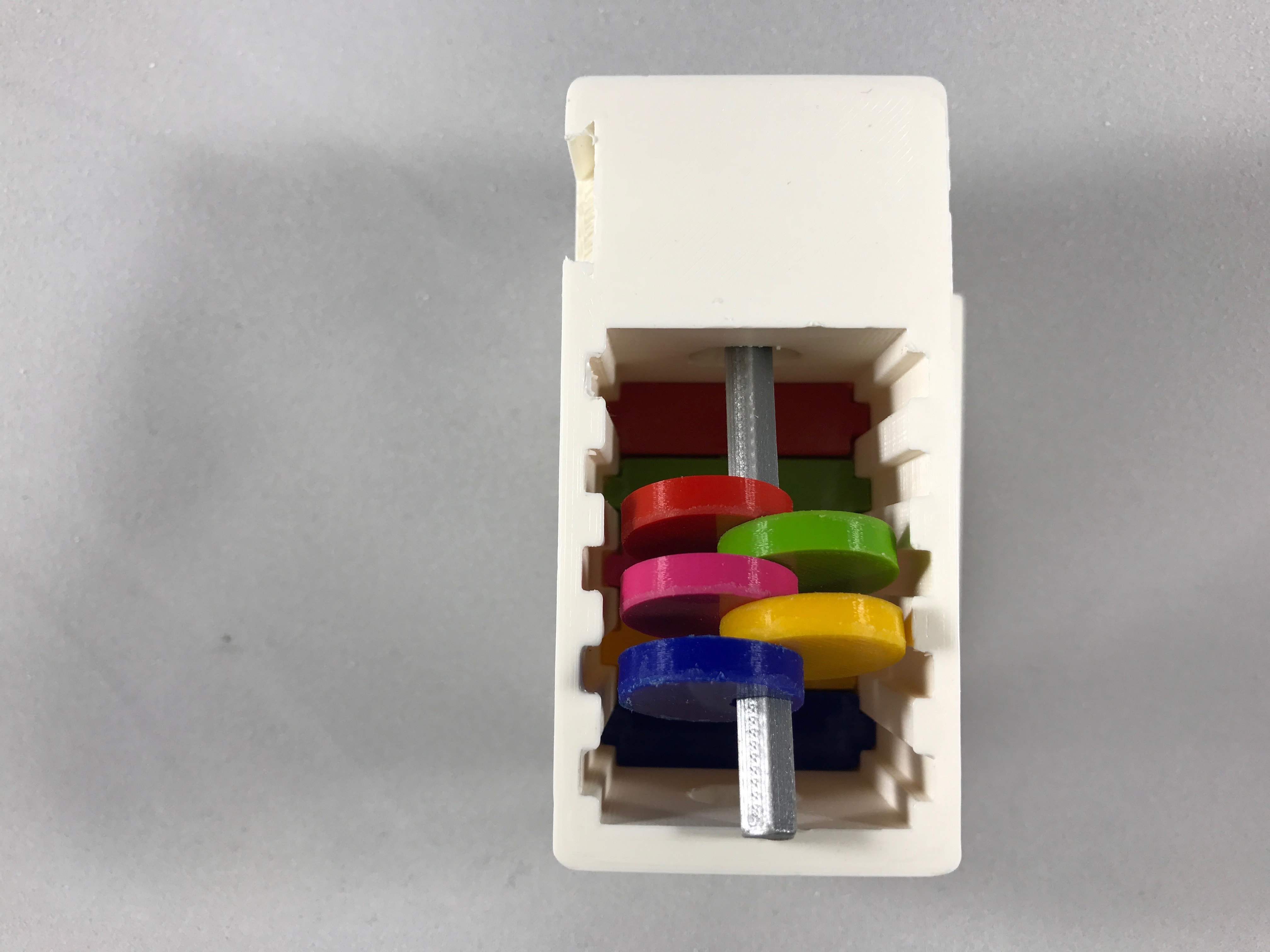
After the steps are installed, the axle and cam lobes are assembled in place. The assembly procedure occurs inside the bottom of "Base.stl" and is somewhat like threading beads on a needle.
Start by inserting "Cam Axle.stl" into the axle hole nearest the short end of "Base.stl".
Next, one by one, slide one "Cam Lobe.stl" onto "Axle.stl", alternating the orientation of each by 180 degrees. The position of each cam lobe on the axle will be set later.
Install the Knobs.
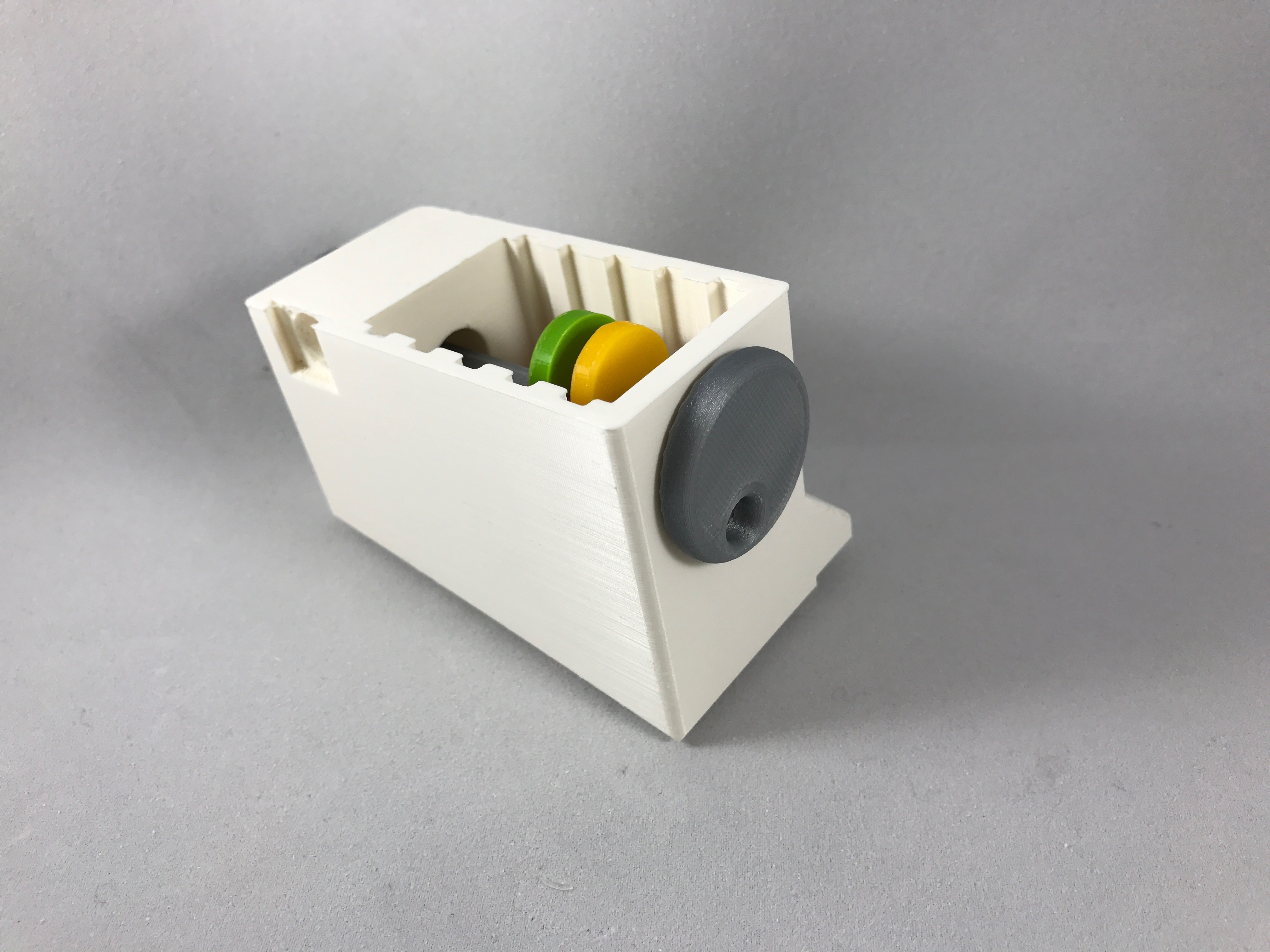
Press one "Knob.stl" onto each end of "Axle.stl".
Align the Cam Lobes.
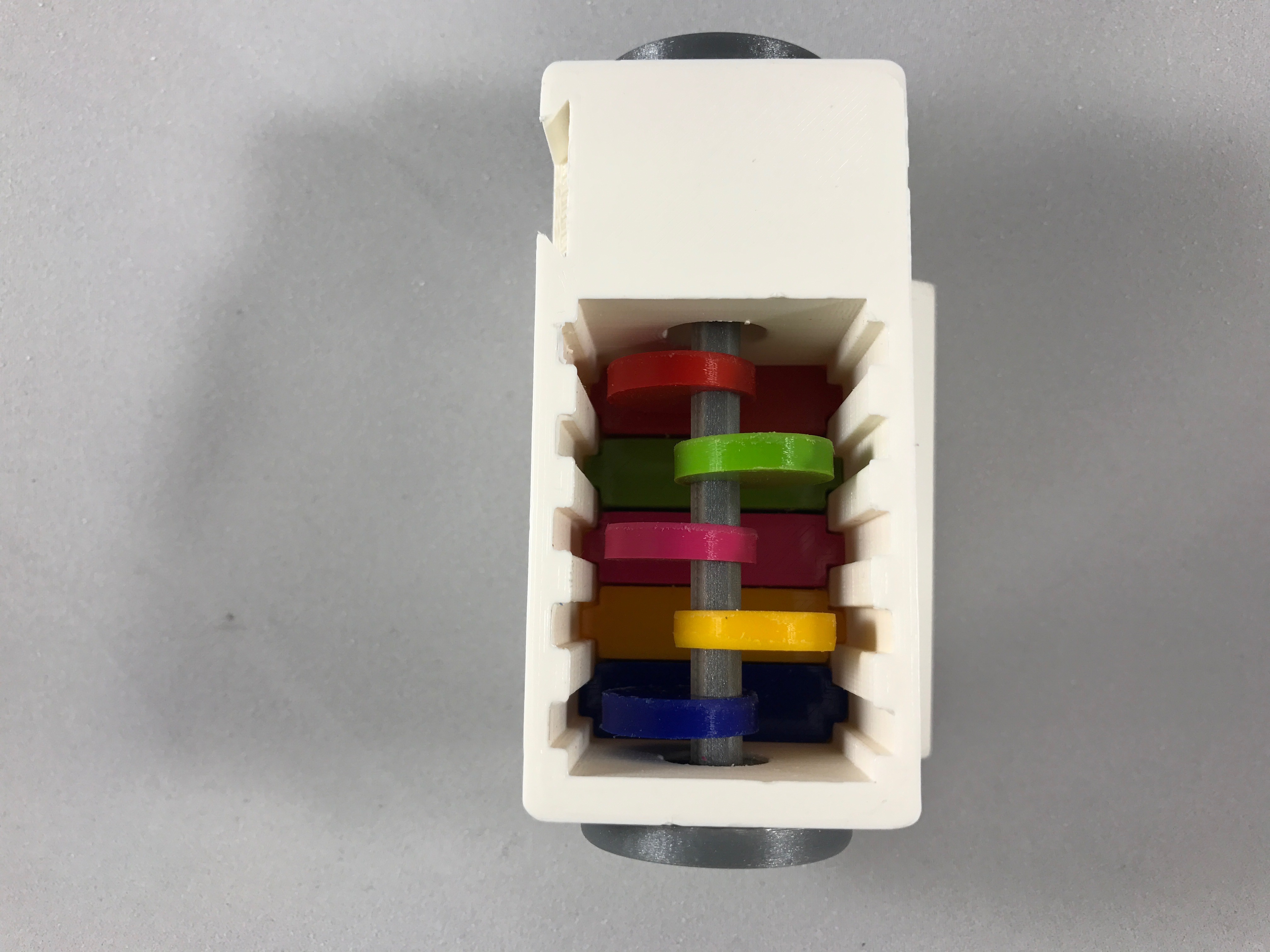
I used needle nose pliers to align the cam lobes with the steps.
Holding the front and rear knobs with one hand, slide each cam lobe into position directly above its respective step using needle nose pliers. It is important that each cam lobe only contacts its own step and not an adjacent step.
Install the Door.
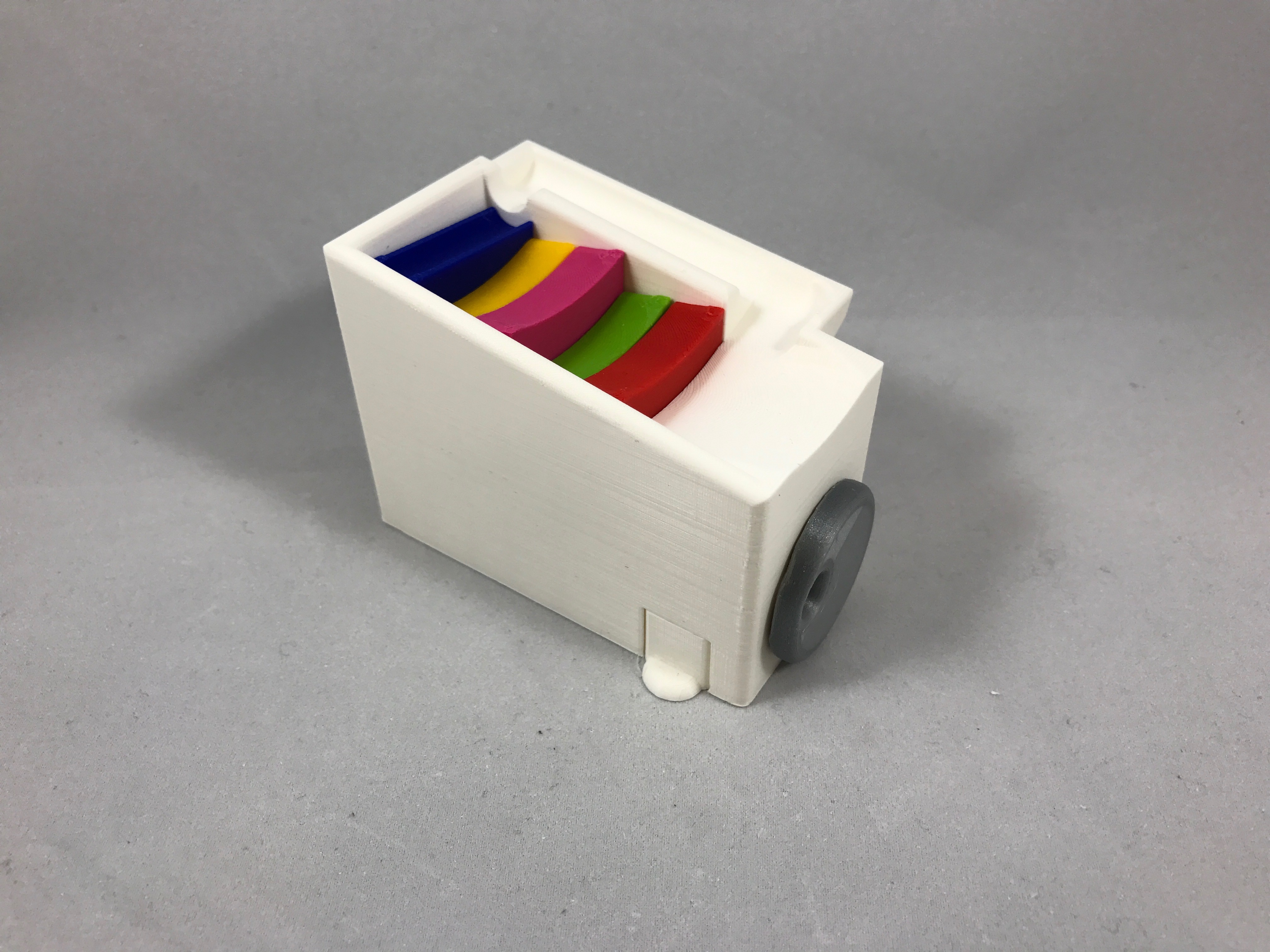
Slide "Door.stl" into position in the door opening in "Base.stl" and you are done!
Hope you like it!