Mapping the Depths
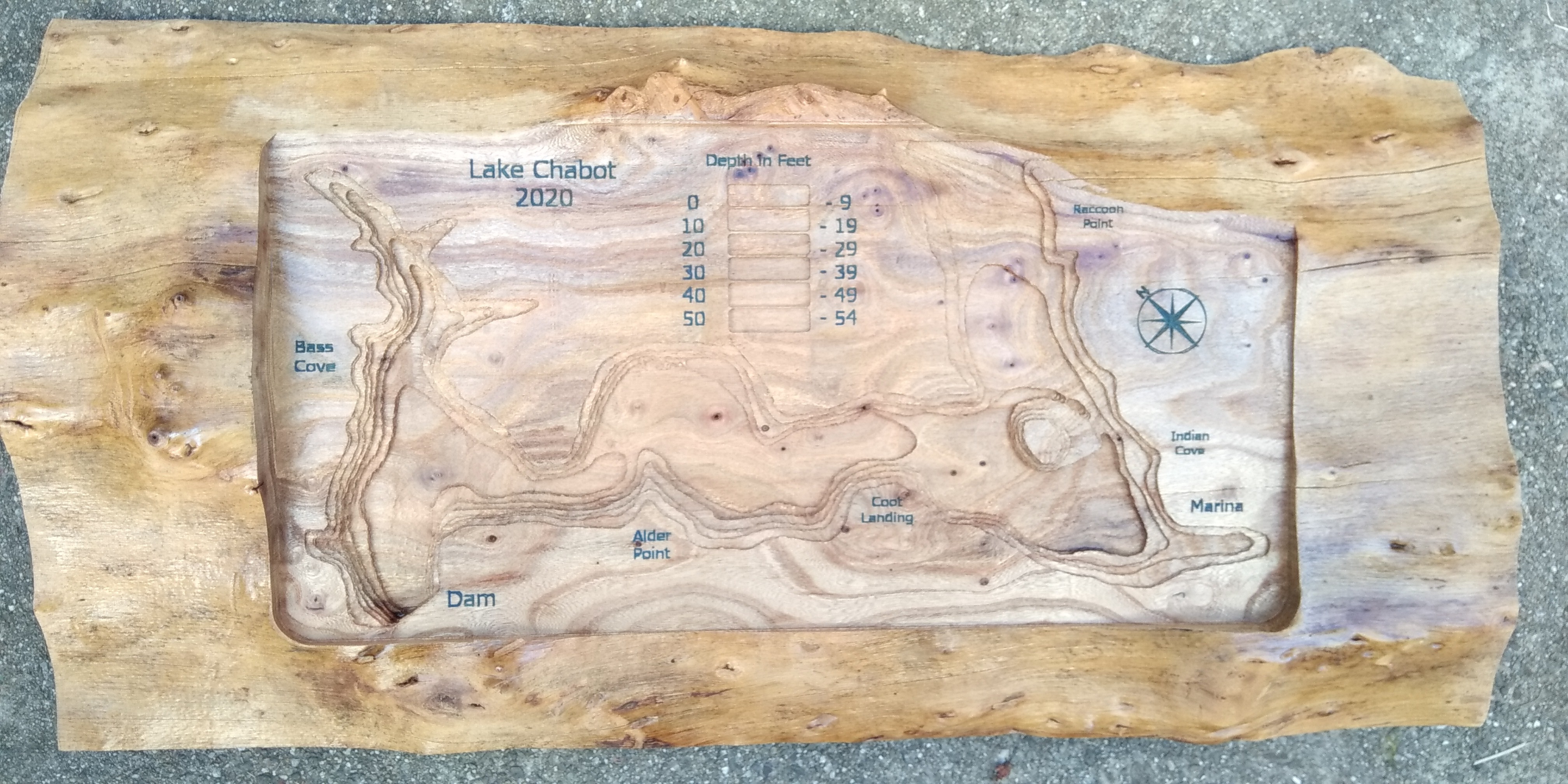
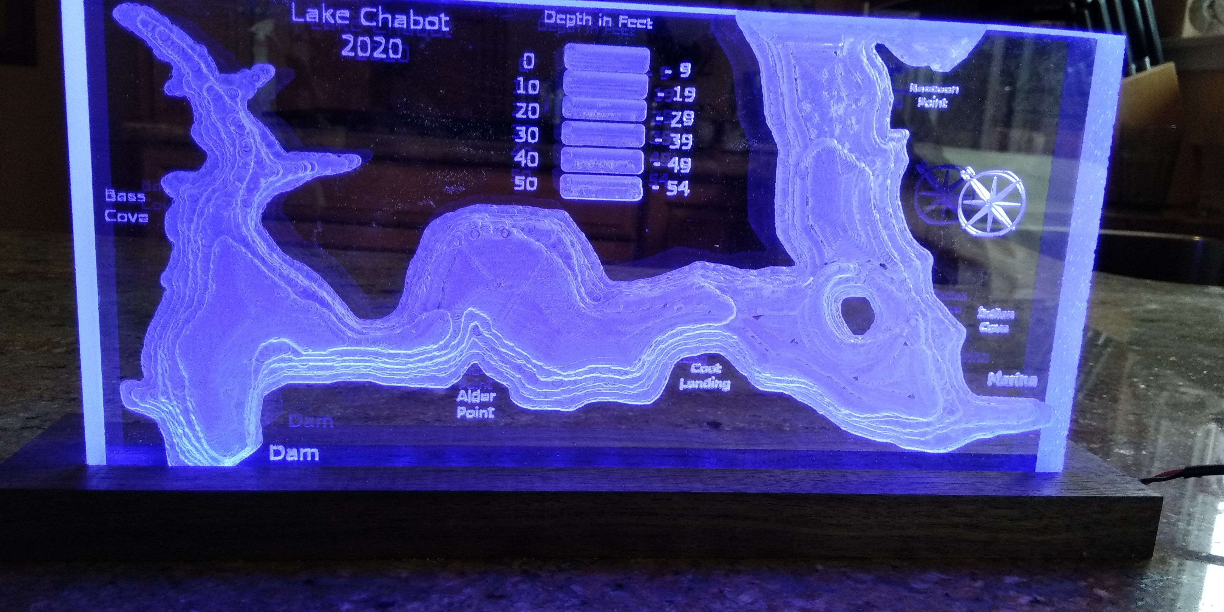
The motivation for this build grew out of the fun I was having trying various carvings on my new CNC machine. I was able to get depth maps of Lake Tahoe and San Francisco Bay from the internet. I worked with them so they’d be right for CNC carving and they came out nicely. But close to my house there is a lake/reservoir for which I could not find any depth information (Lake Chabot in Castro Valley, CA). I wanted to do a carving of its depths.
The only solution: measure the depths myself, create my own contour map, and change it to grayscale for carving. Here is how I went about it.
The Boat
The Boat
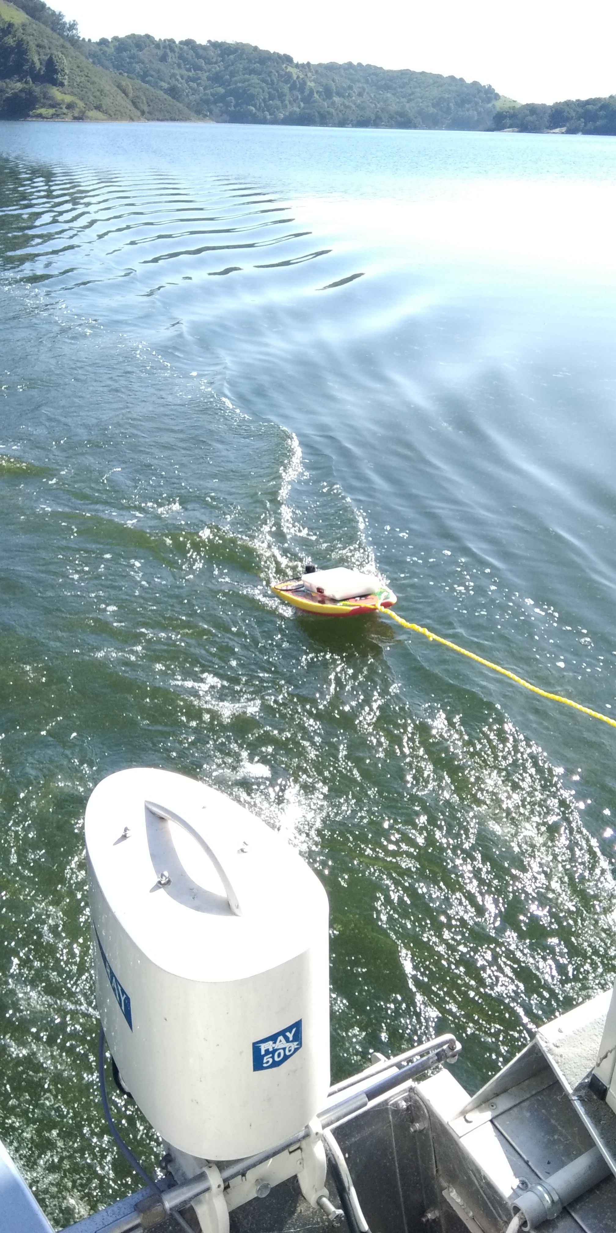
For gathering data points I would need to navigate all over the lake, logging depth and latitude and longitude. My initial approach was to build a robot boat which would navigate over a planned route and then come back to the dock. I had a lot of trouble getting it to steer straight, and it was very sensitive to the wind. In addition, it seemed to always leak. I eventually abandoned that idea in lieu of a small craft which could be towed behind a rental boat.
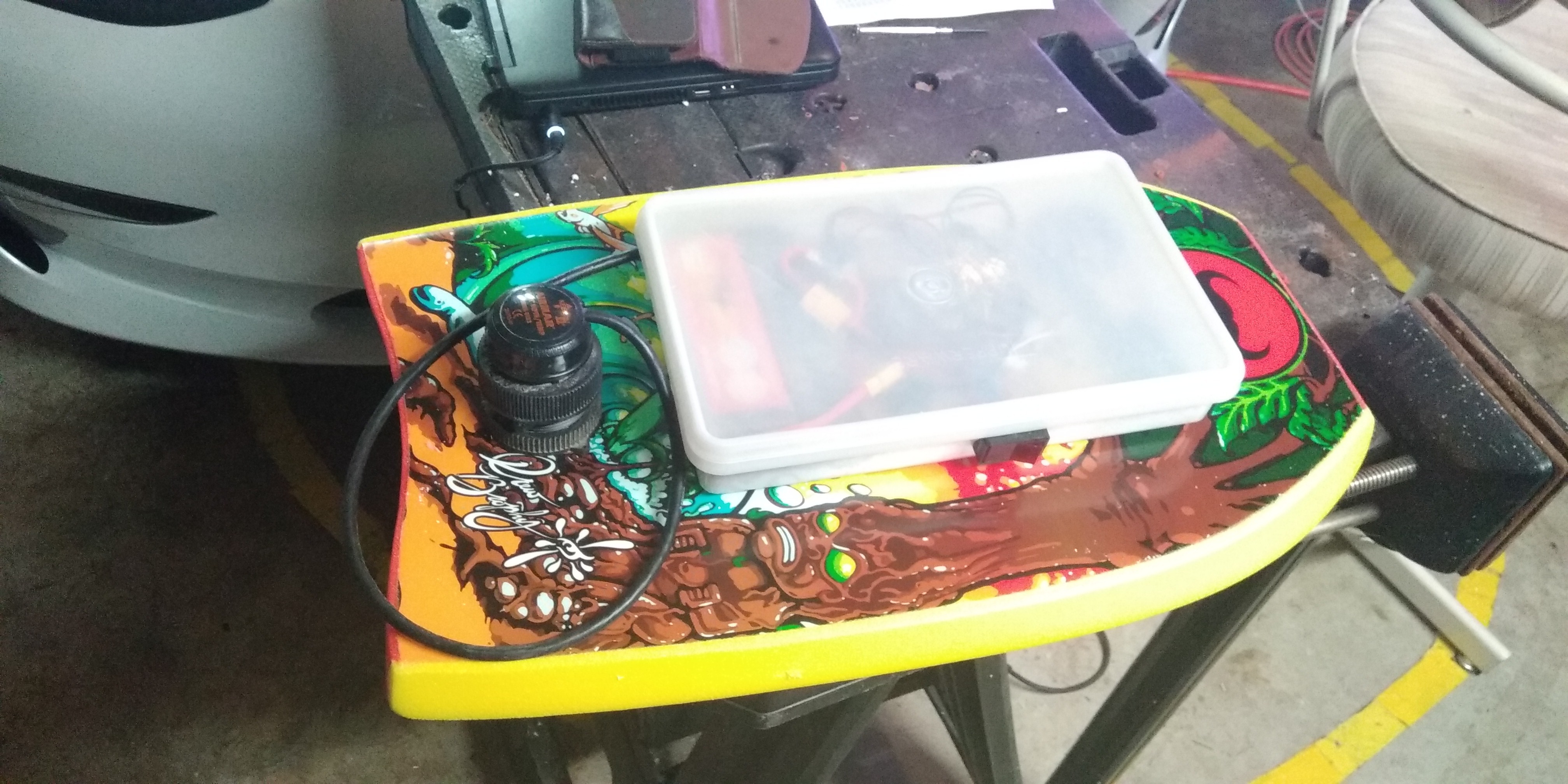
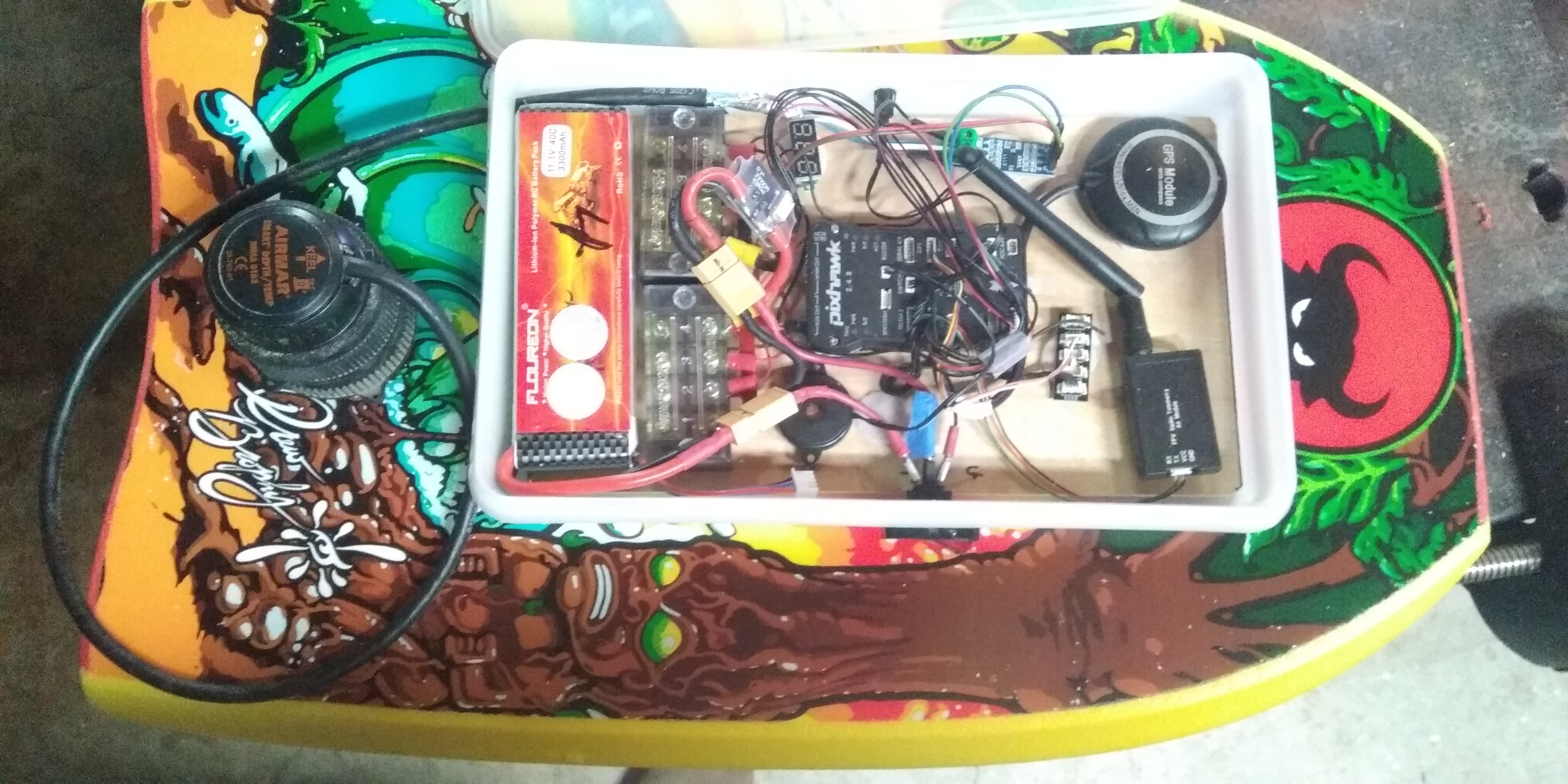
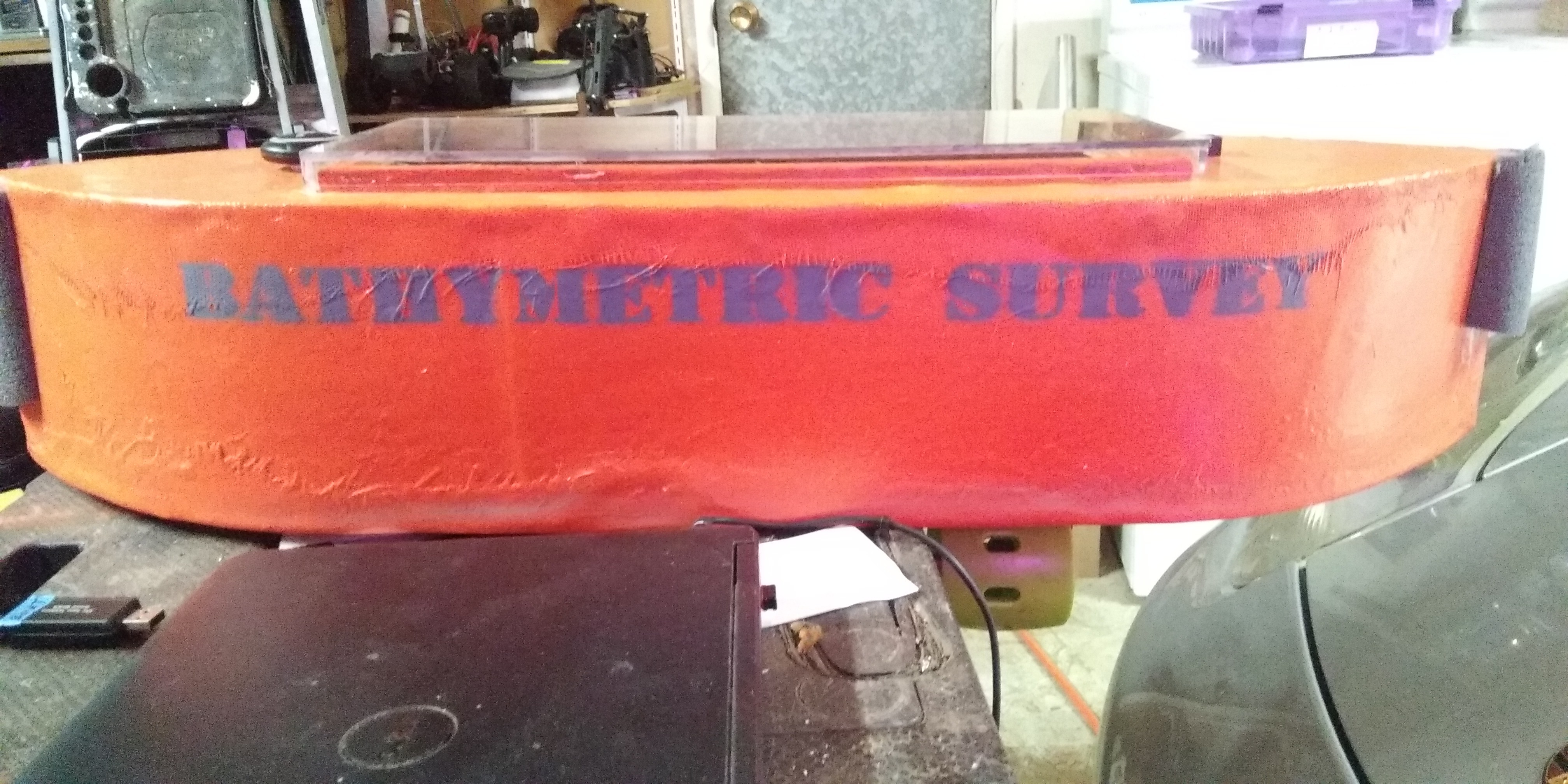
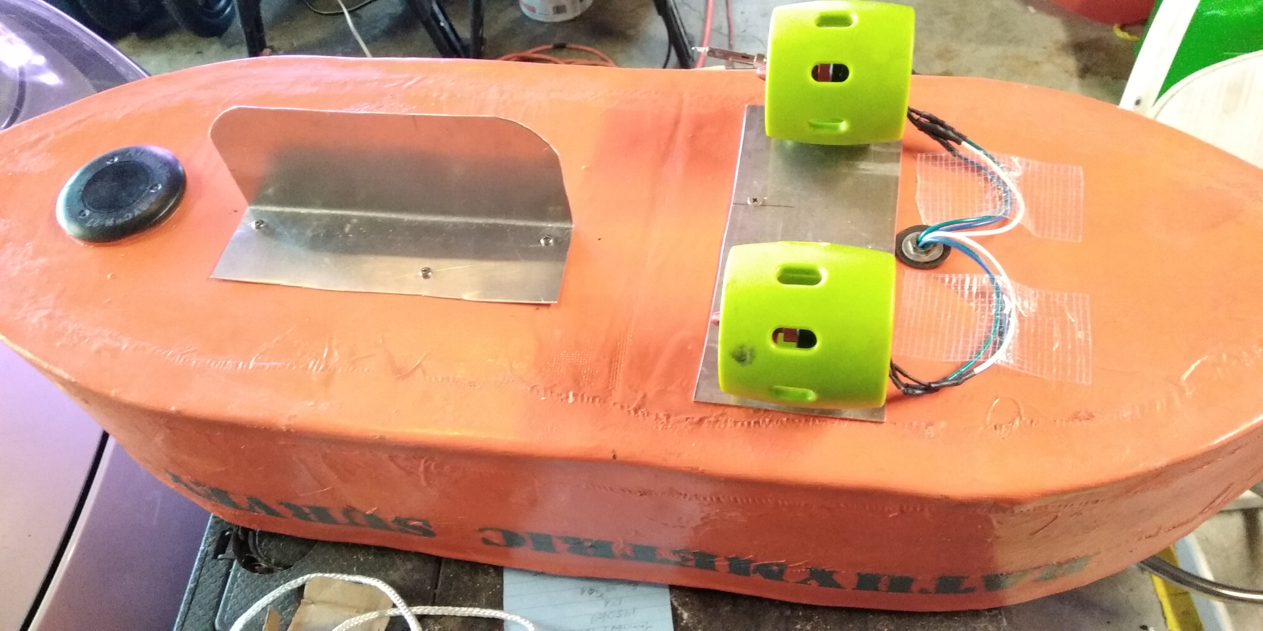
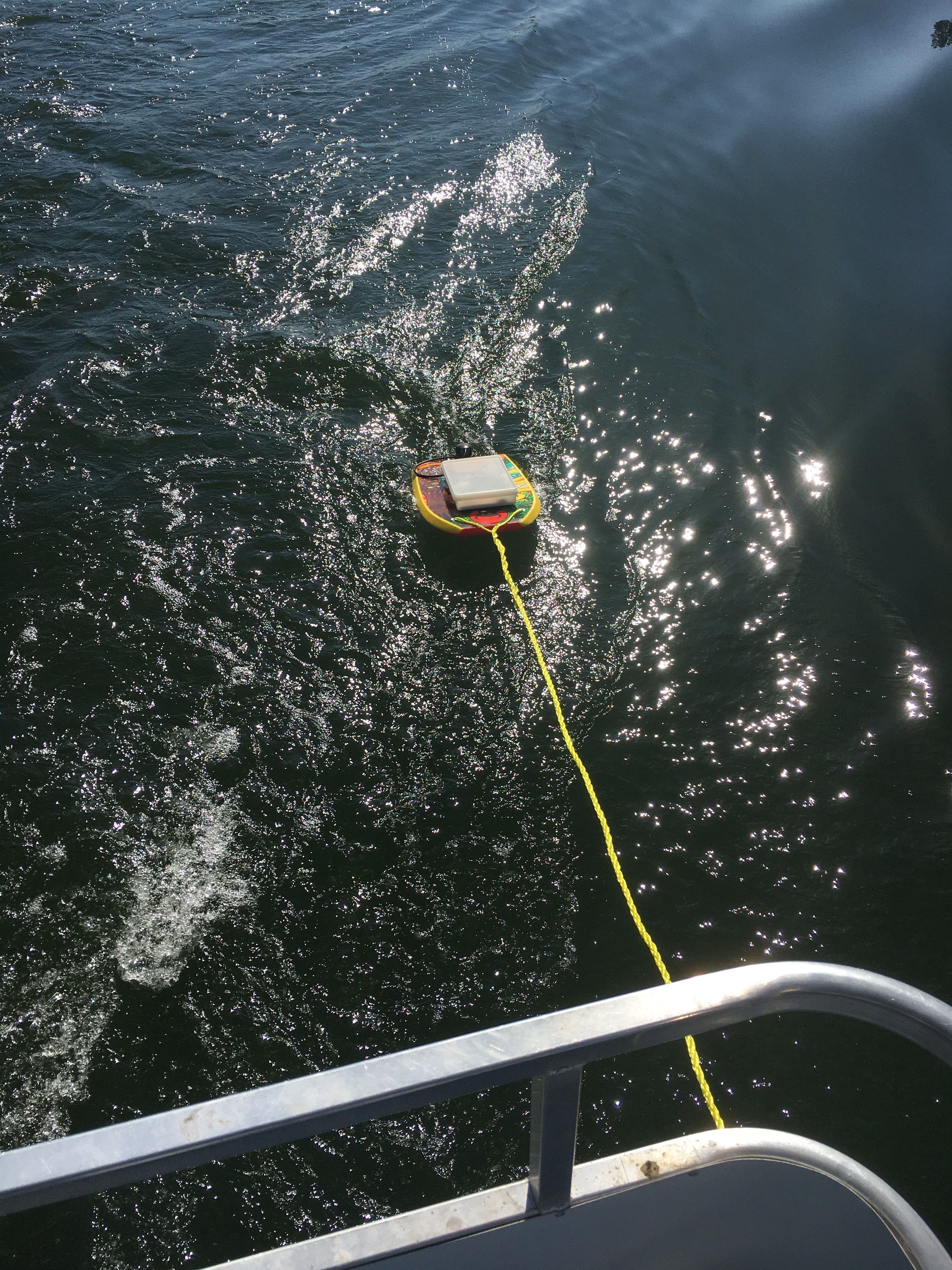
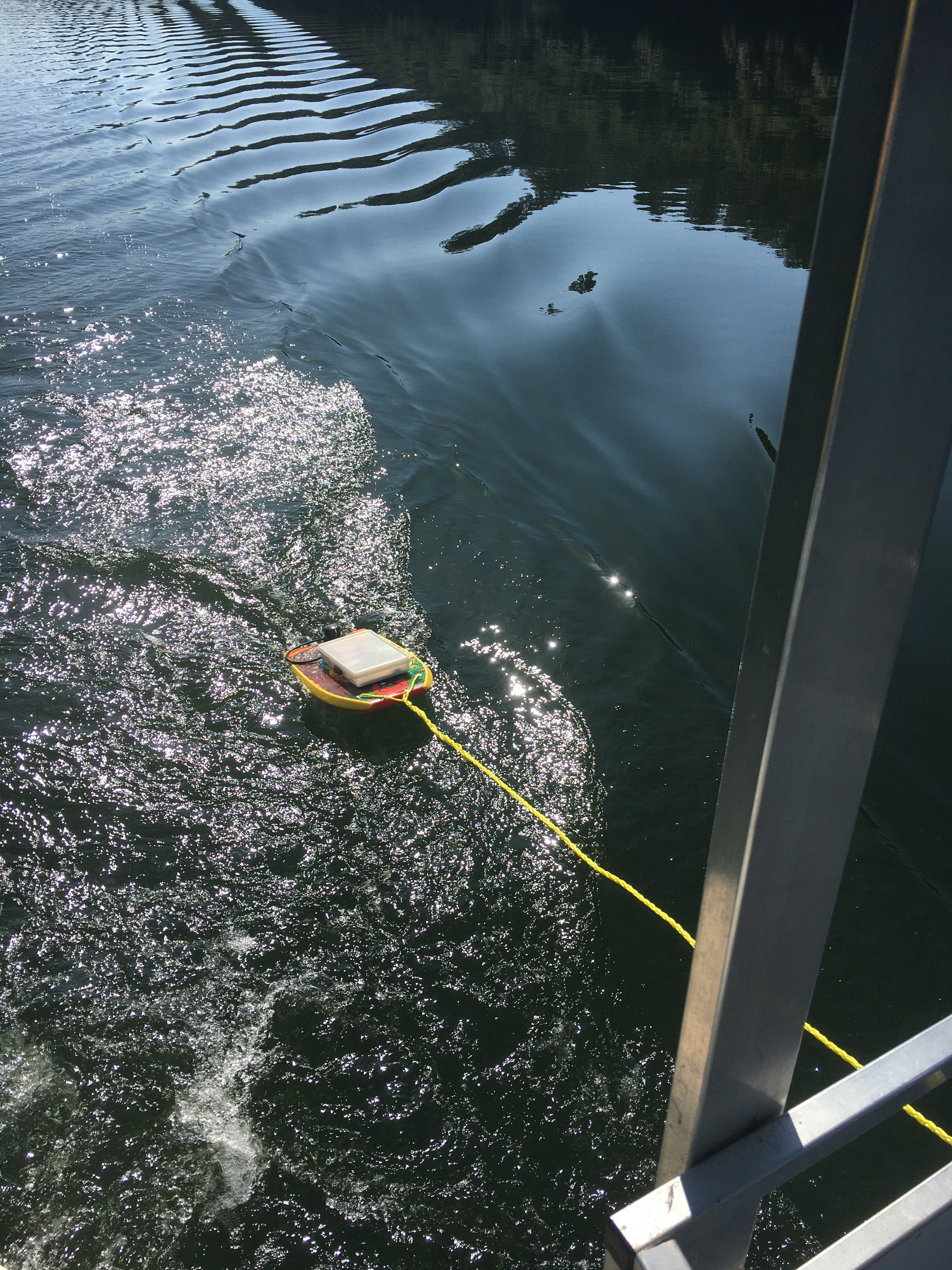
After the ill fated “robot boat”, the drag-behind boat was simple. I used a small boogie board, drilling a big hole for the depth sounder and attaching a Tupperware container on top for the electronics. This boat was much simpler than its predecessor and only a subset of the electronic components were needed.
Electronics and Electrics
- · Depth sounder (Airmar DT800 NMEA – produces NMEA depth sentences in RS458 signal protocol)
- · Pixhawk flight controller (configured for surface boat)
- · RS458 to TTL (serial) adaptor)
- · Power module (measures volts and amps) – not really needed
- · GPS/Compass (external) – compass no longer necessary
- · Beeper and voltage meter
- · 5A 12v automotive Lighted switch
- · Terminal blocks for 12v + and –
- · 3300 mah lipo battery (more than enough for electronics only)
Software
- · Mission Planner PC software
- · ArduRover (ArduBoat) Navigation firmware
- · Excel
- · Google My Maps
- · Google Earth
- · Photoshop
Gathering the Data
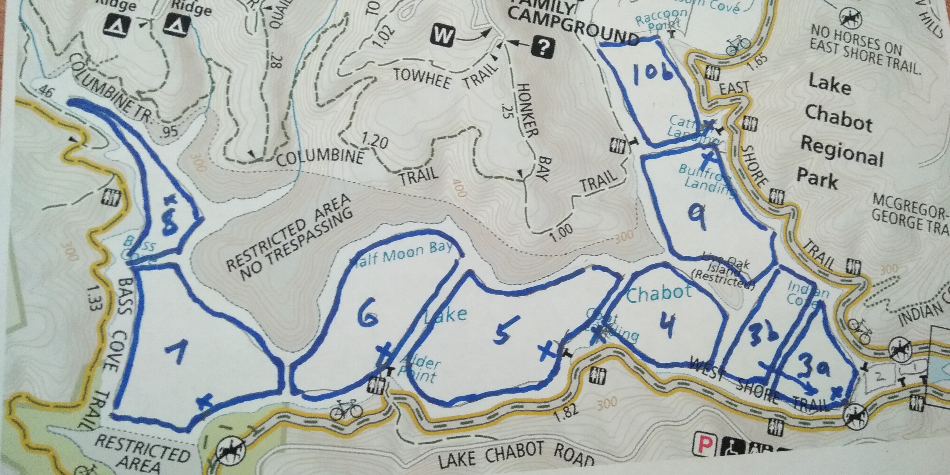
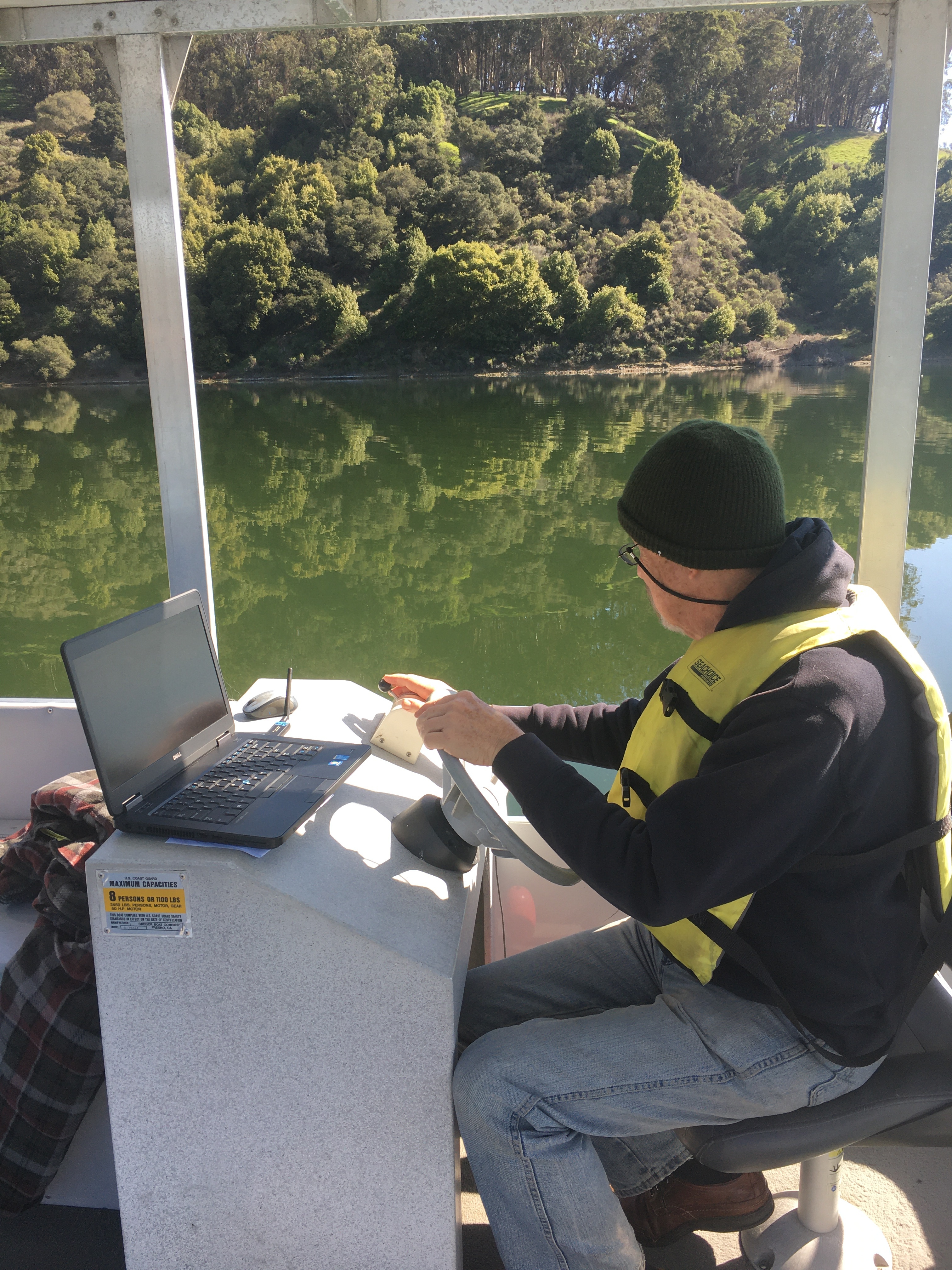
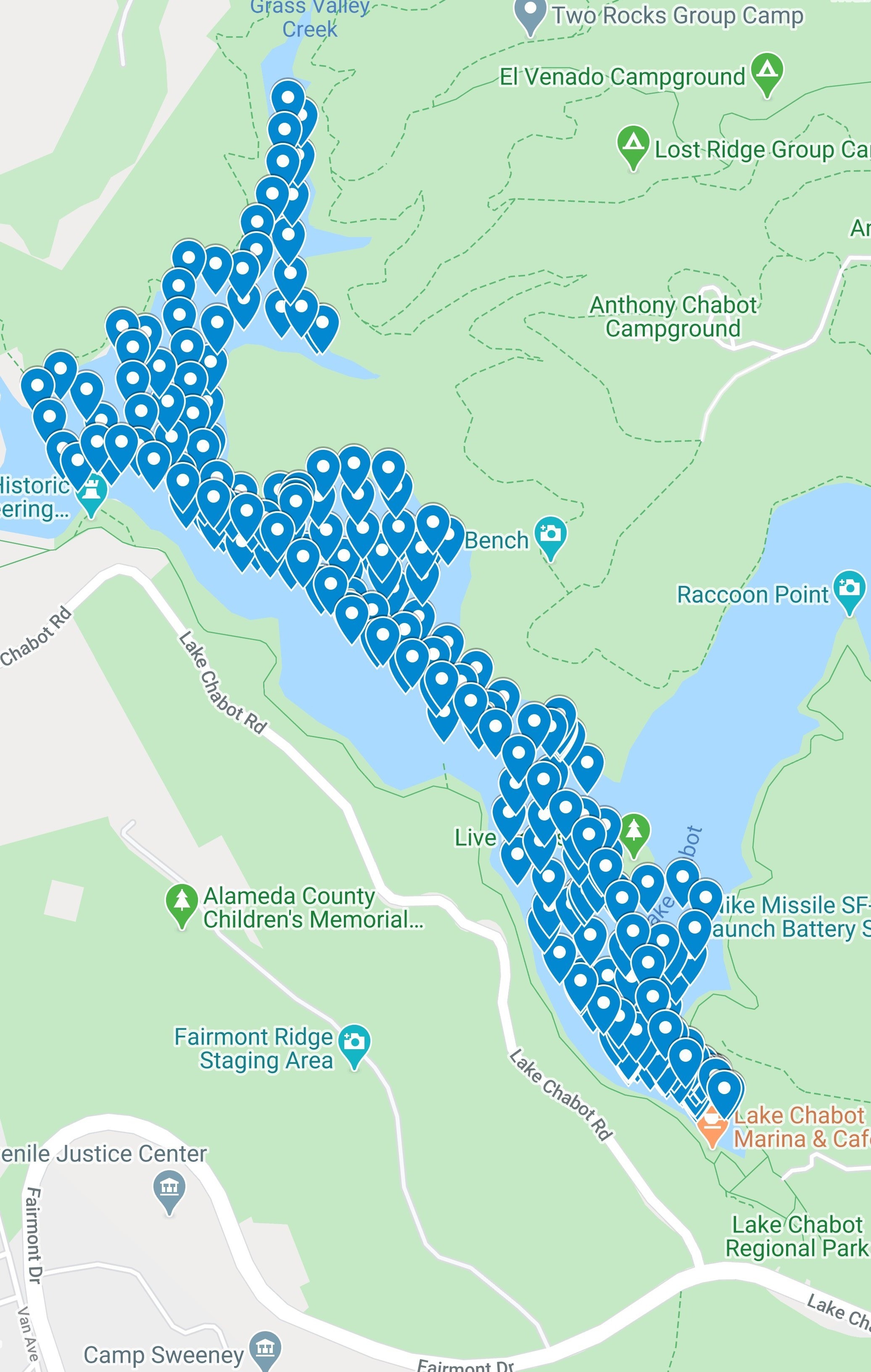
Lake Chabot is shaped roughly like a Vee, with the upper right arm being a very shallow area, often filled with reeds. If I tried to carve the whole lake, dry land would overwhelm the carved portion. So I decided to omit much of the upper right, turn the map 45 degrees and concentrate on the interesting portions.
My initial plan was made for the robot boat, but it formed the overall strategy for navigating the rental boat. It took a 2 ½ hour session to gather most of the data, and another ¾ hour session a few days later to gather the rest. I retrieved the DPTH data in CSV (comma delimited) format from the on-board log using Mission Planner and found I had over 16,000 data points. Now what?
Per comment from LukeB81 I've added raw data as CSV files. Note that Zero depth readings at the beginnings and ends of the voyages have been deleted. Also, my voyage paths were not totally comprehensive as one will find if locations are charted (i.e. Not every part of the lake was traversed.)
Massaging the Data
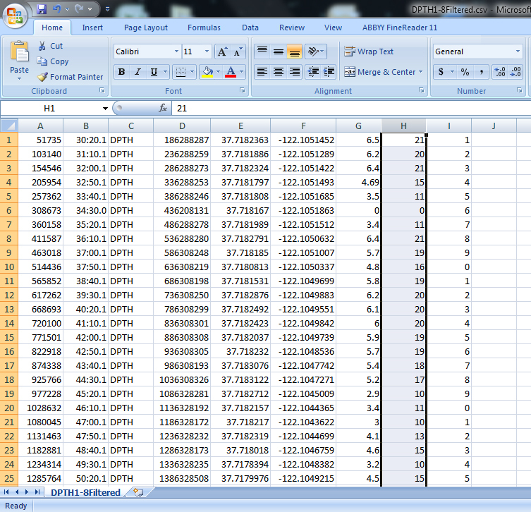
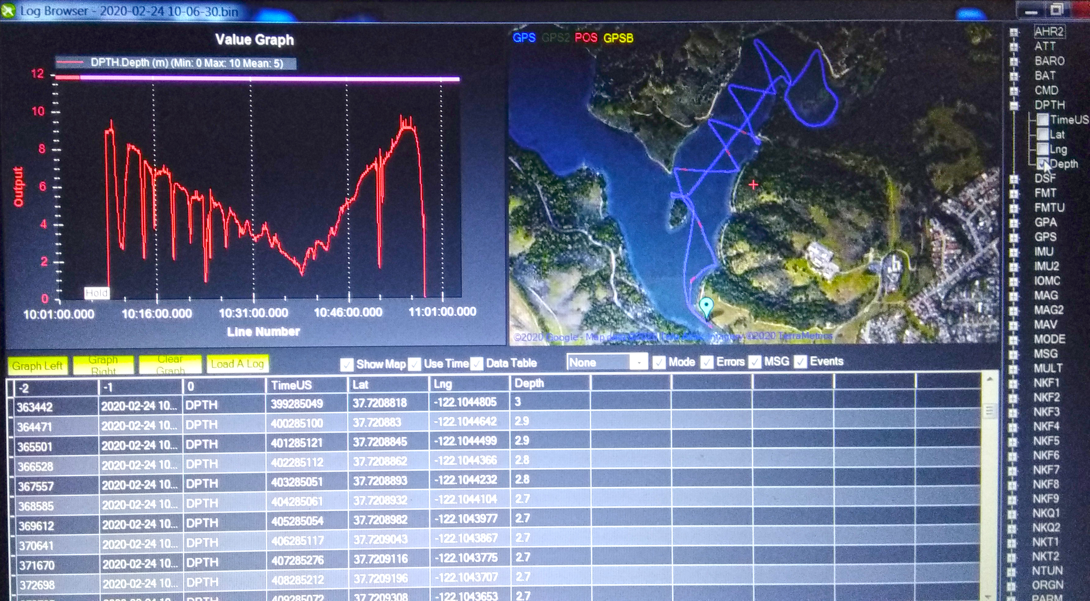
My initial hope was to use specialized software like Golden Software Surfer to draw the contours. It seemed like very capable software, but after trying all combinations and variations I still couldn’t get it to work for me. So the next plan was to draw the contours manually. But what to do with all that data. The depth sounder takes a reading every second. The resultant file of over 10,000 valid data points is way too many for any manual activity.
So I used Excel to winnow the data points down to fewer than 300. This left plenty for mapping purposes. Depth data was in Meters so I created an Excel column that showed Feet. I brought the slimmed down CSV file into Google My Maps and it showed the data points on the map. When you click or hover over each point, the depth shows.
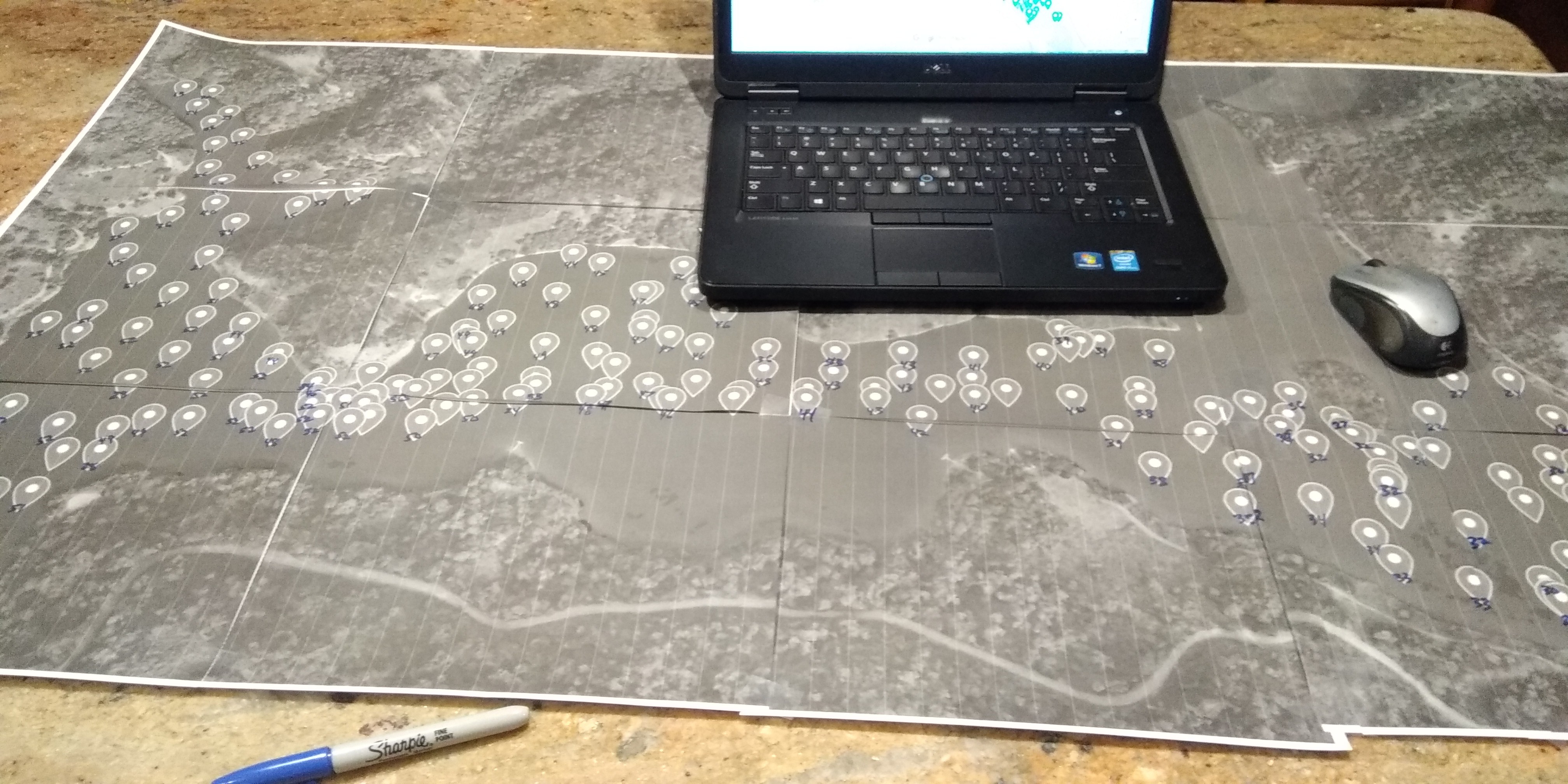
I printed out a large version of the “Google My Maps” map, taping together 12 pieces of letter sized paper. But enlarging the map also enlarged the data points, making them overlap and obscure each other. The next approach was to export the data from Google My Maps in KMZ (Google Earth) format. I printed out another large map using Google Earth and the data points stayed a manageable size.
The next step was to use the PC to hover over each data point and write the depth (in feet) on the large paper map. It didn’t take too long and it began to show the status of the lake. The lake was formed by a damming a valley over 100 years ago. It was remarkable how flat the bottom was. Years of silt had filled in any trace of a valley. The only trace of original topography was the very steep portions next to shore. This is Not a lake for wading.
Science Stops and Art Begins
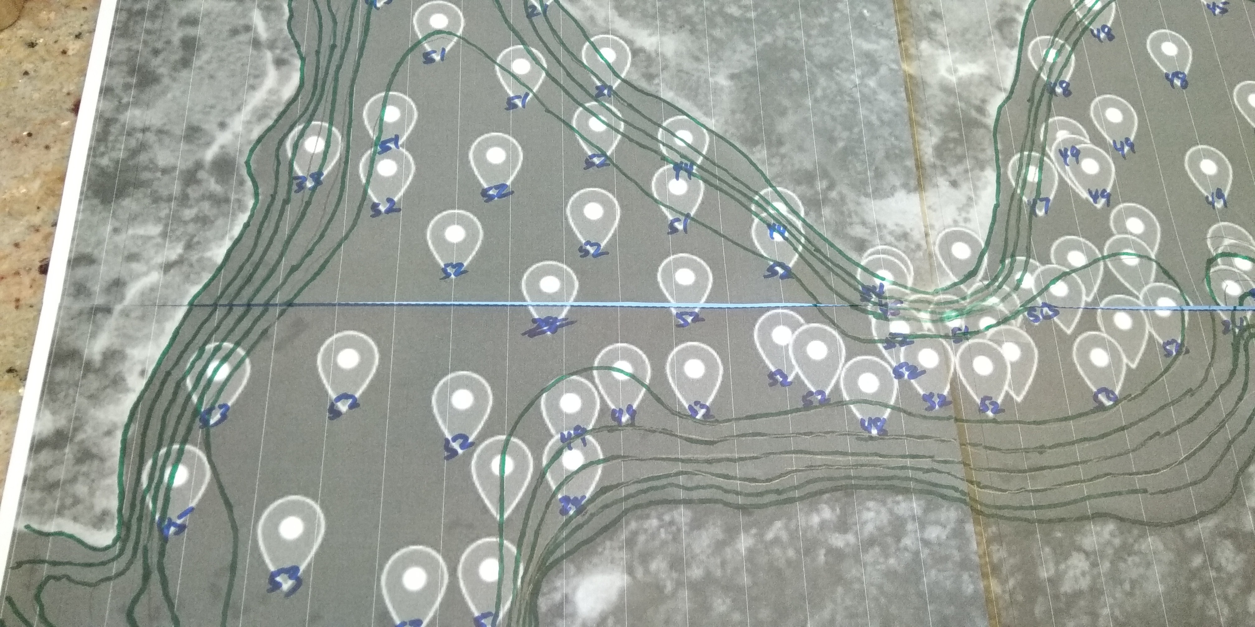
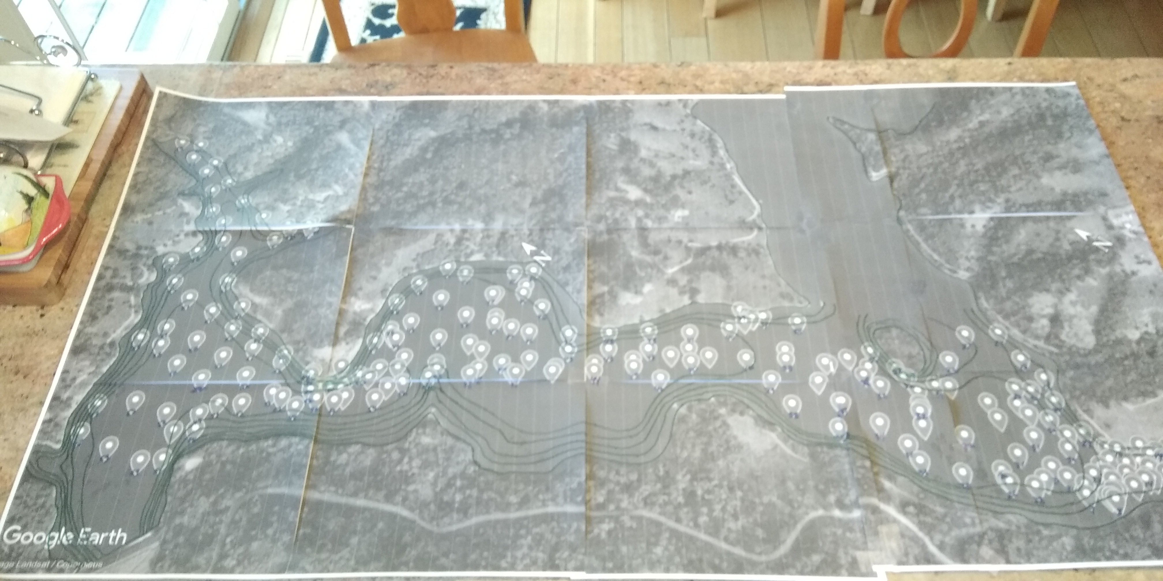
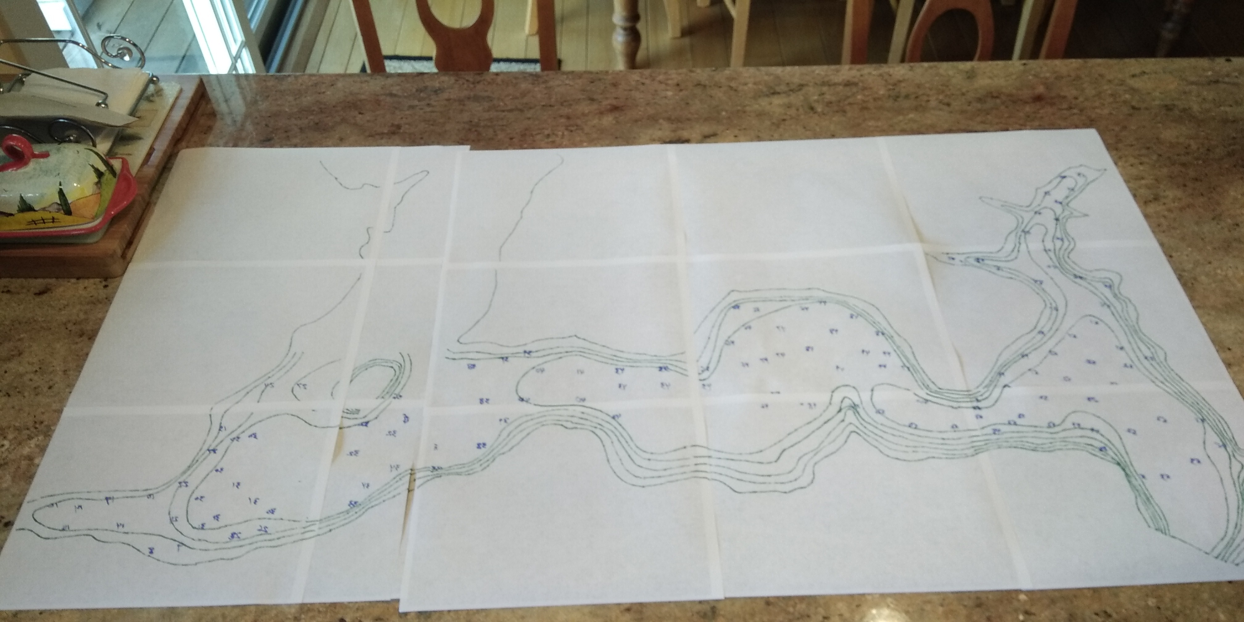
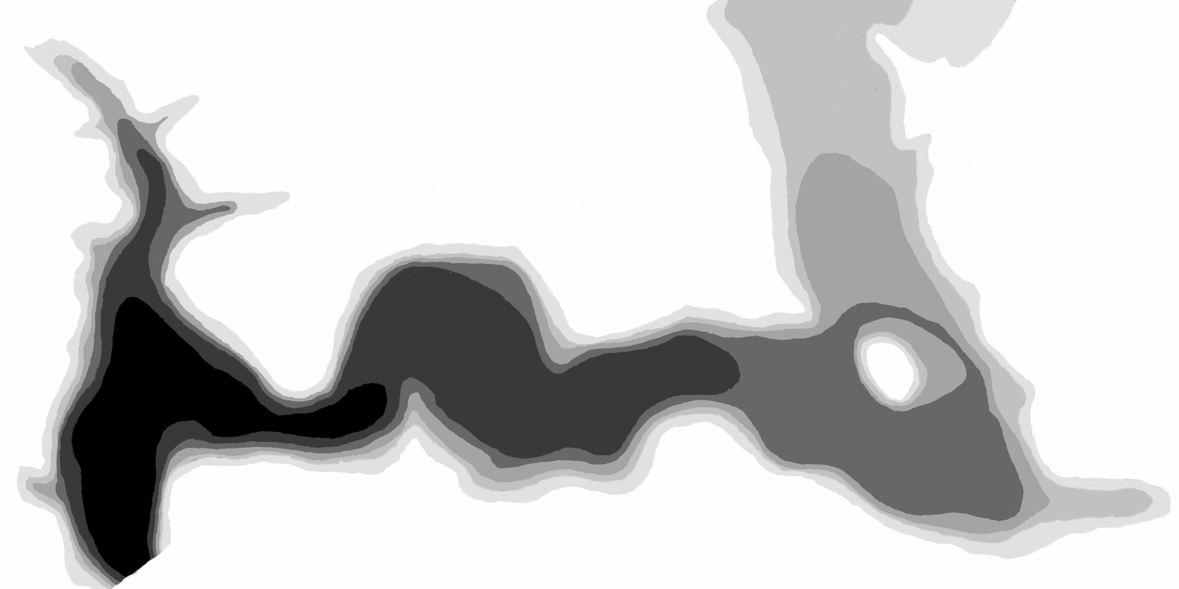
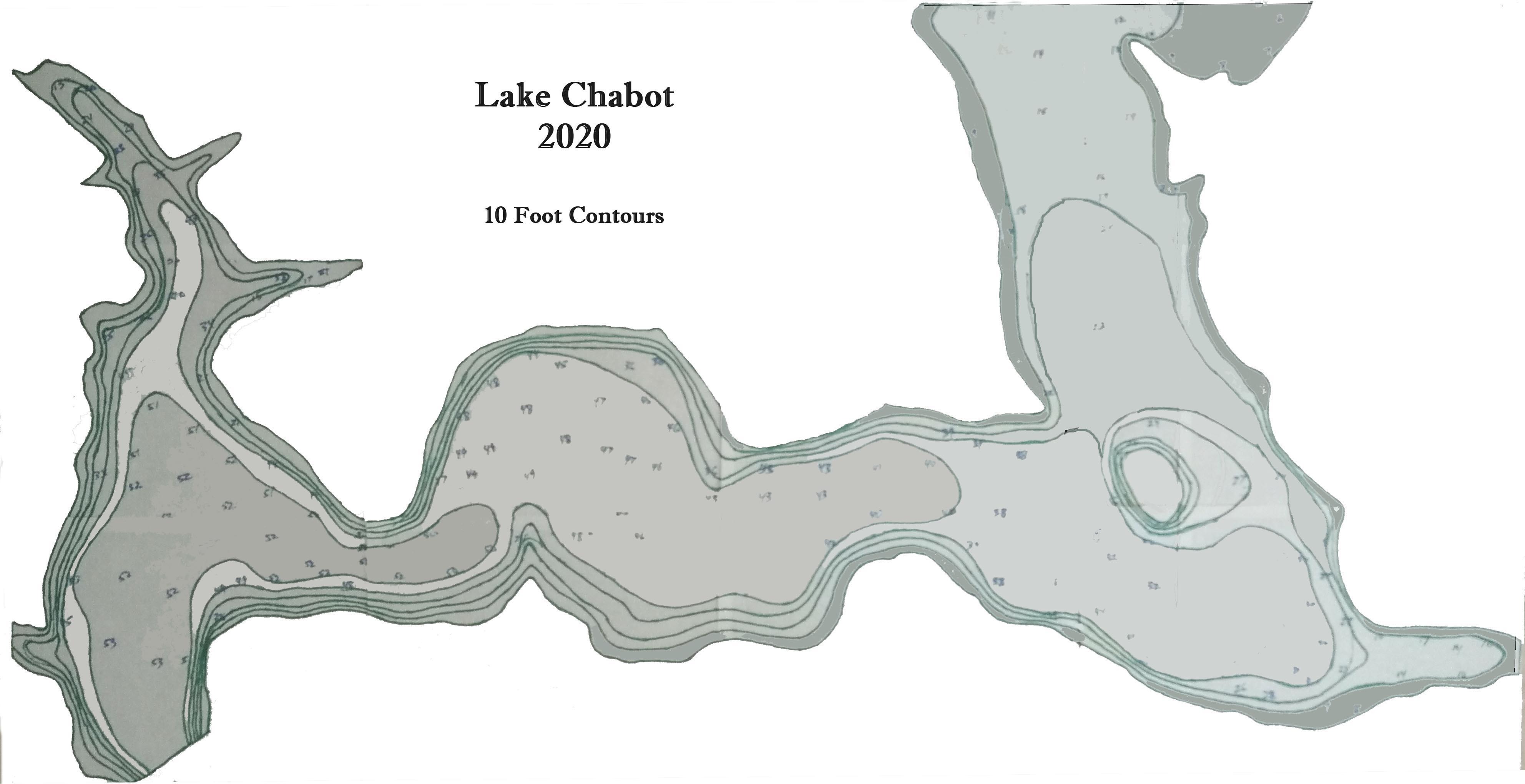
The deepest parts were just over 50 feet, so I decided that 10 foot intervals would make a manageable number of contours. I started with the deepest, drawing a contour to contain the 50 and over data points. Then contours to contain the data points in the 40s, 30s and so on. There was a certain amount of interpolation, interpretation, and guessing involved in this part. But I think the result is fairly accurate and based on real measurements. Now I had contours drawn on a very busy satellite view map.
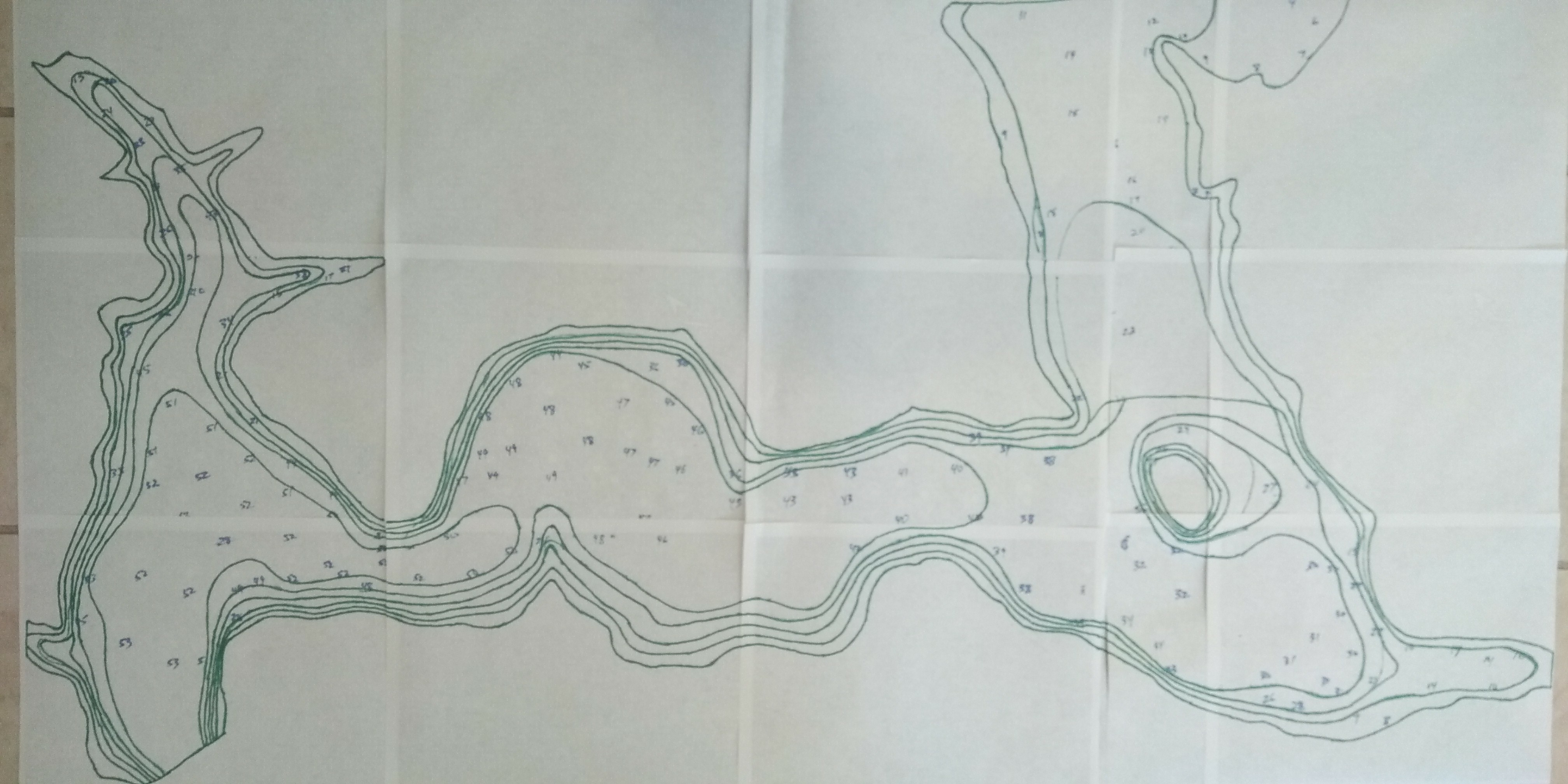
I turned over the paper map and by happy surprise, the Sharpie marker I used to draw contours had bled through showing the contours nicely on the white back side. Cool! I had planned on using tracing paper to make a map suitable for photography, but that wasn’t necessary. After connecting a few broken lines (where it was taped) I took a picture of the back side of the map and brought it into Photoshop.
This part was a bit tedious. In Photoshop, I used the Paintbucket tool to fill in contours, starting with black for the deepest, and with lightening shades of gray for successive shallower depths. I also used the Brush and Pencil tool to clean up portions where the Paintbucket result was not complete. The contour lines themselves had to be one of the shades of gray. In the end, I had a grayscale map ready for carving.
Carving Results
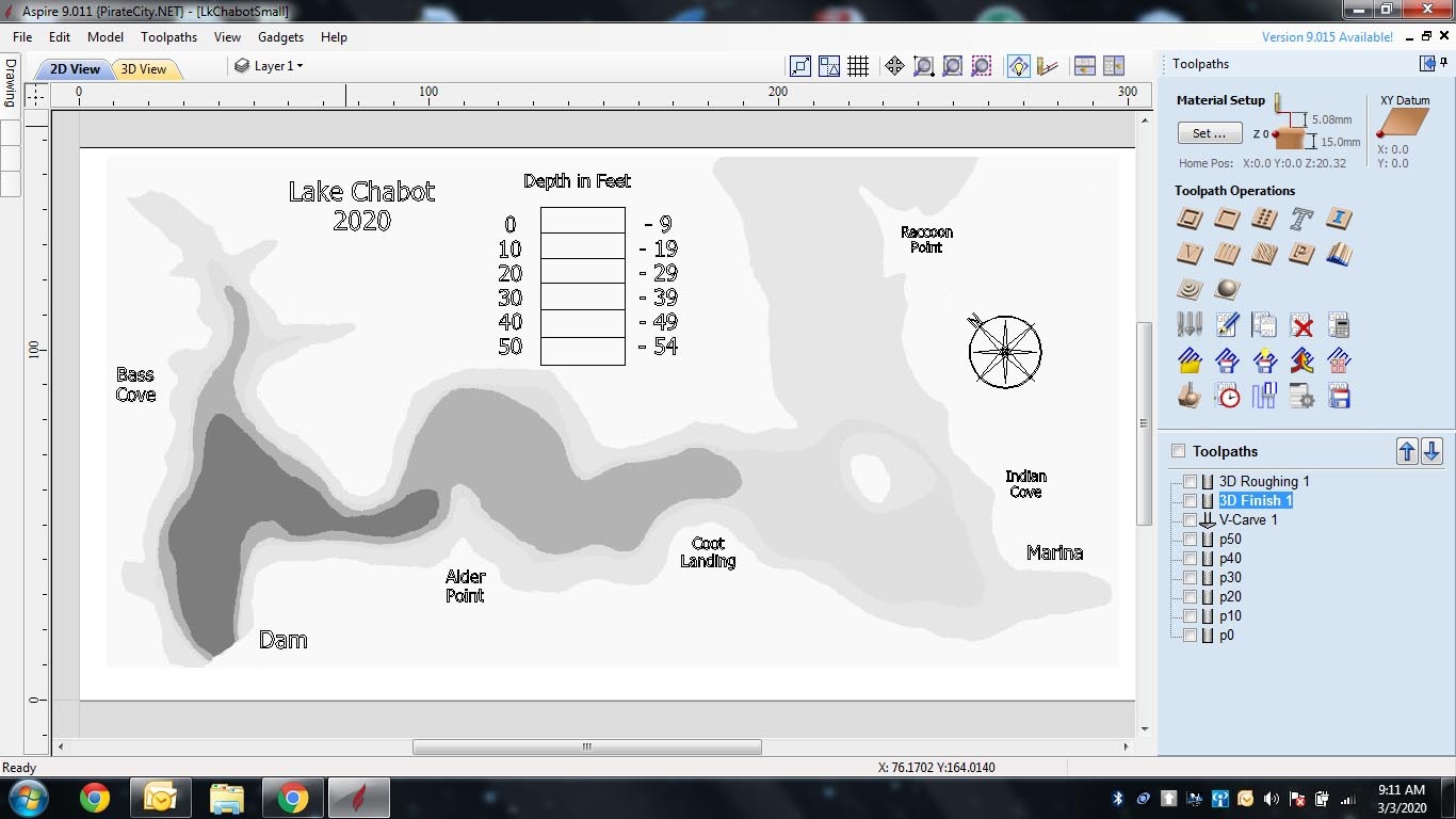
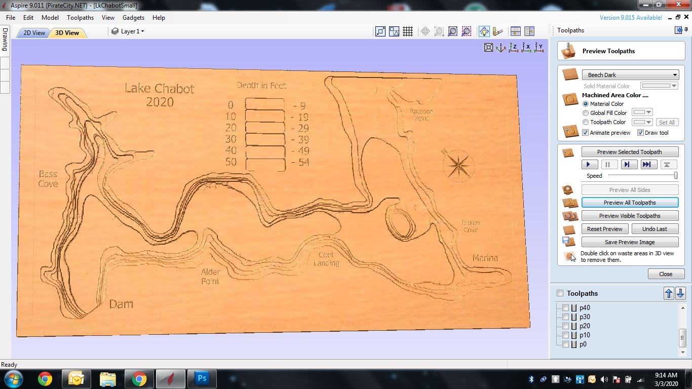
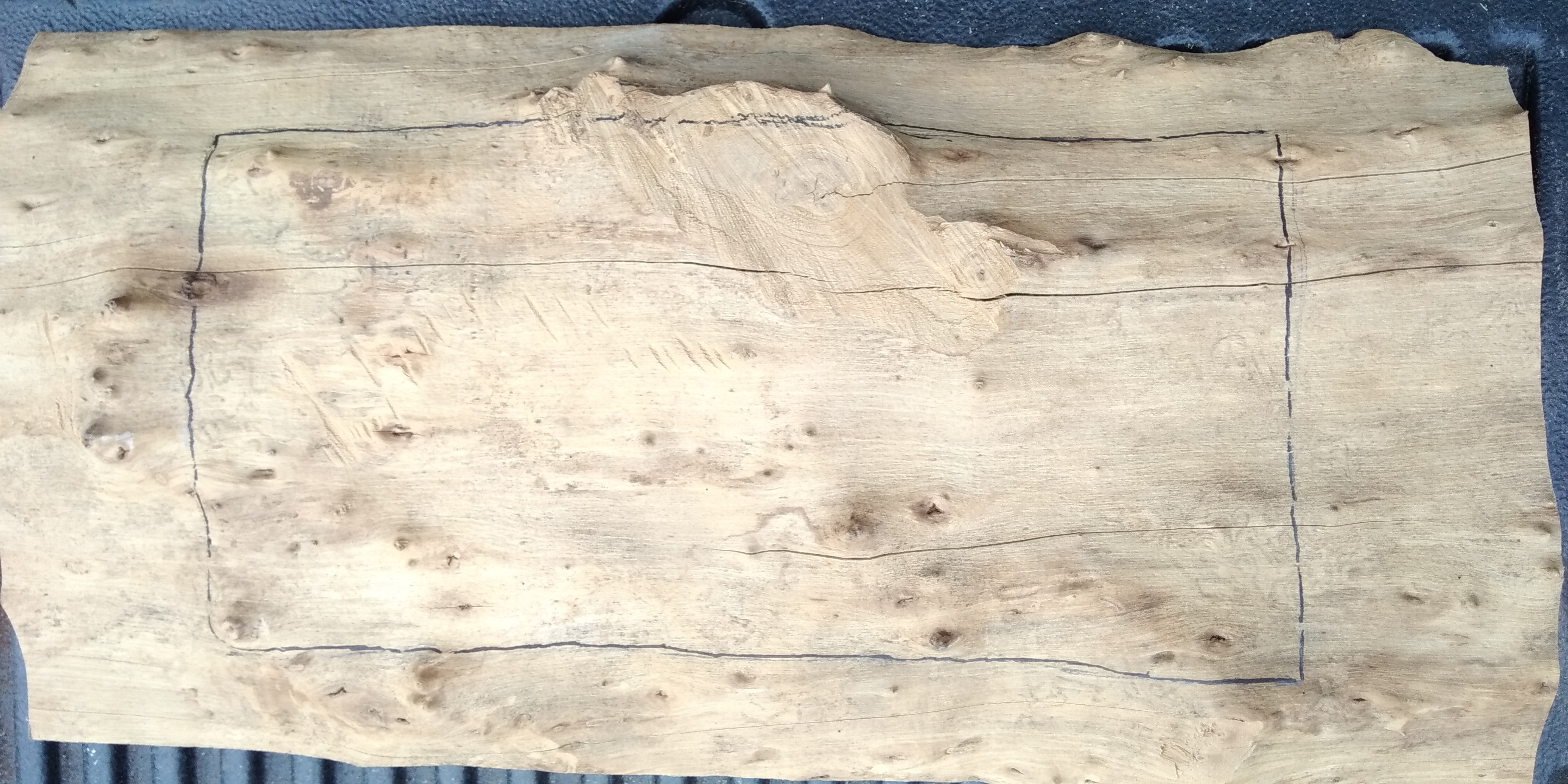
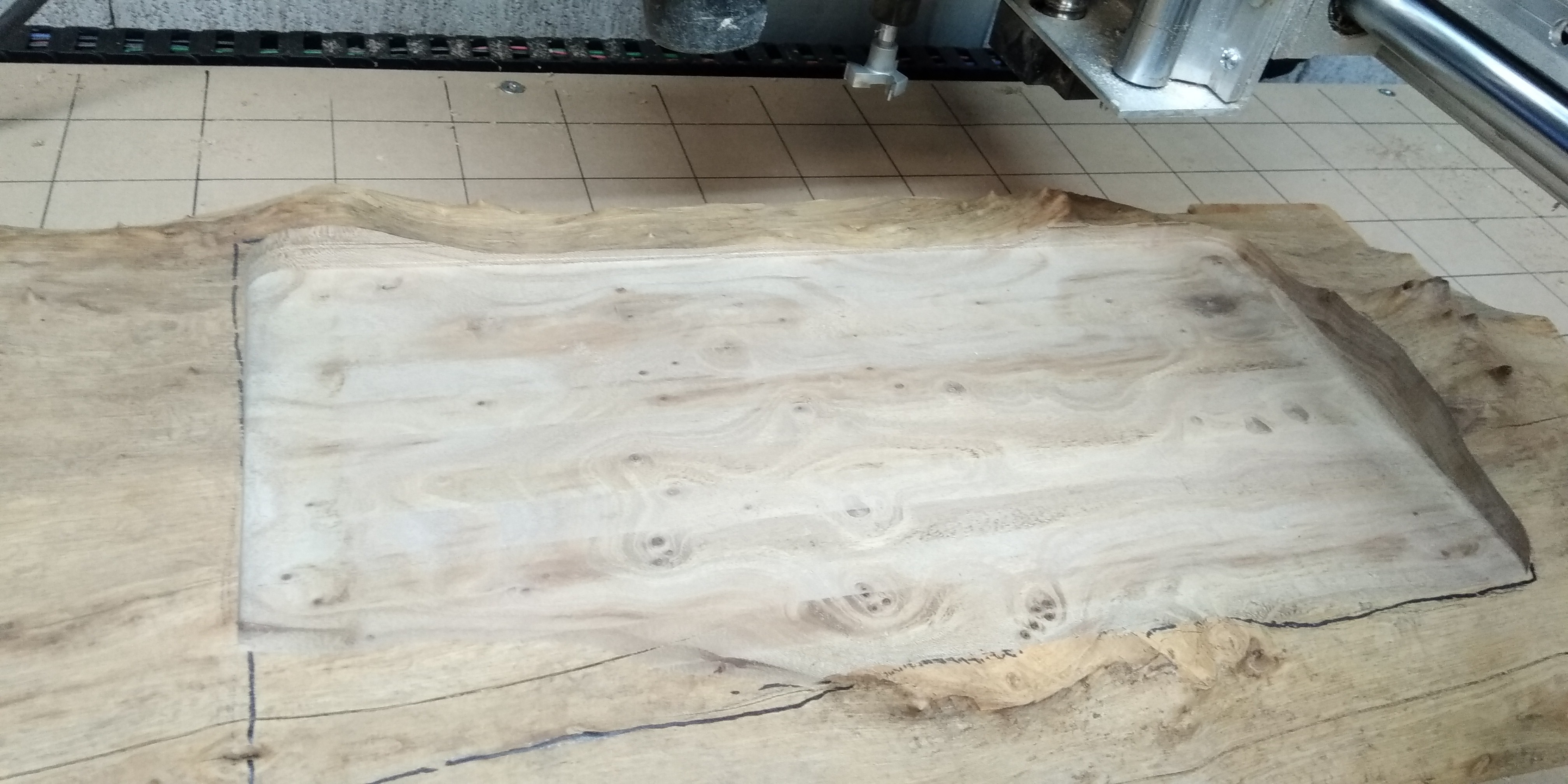
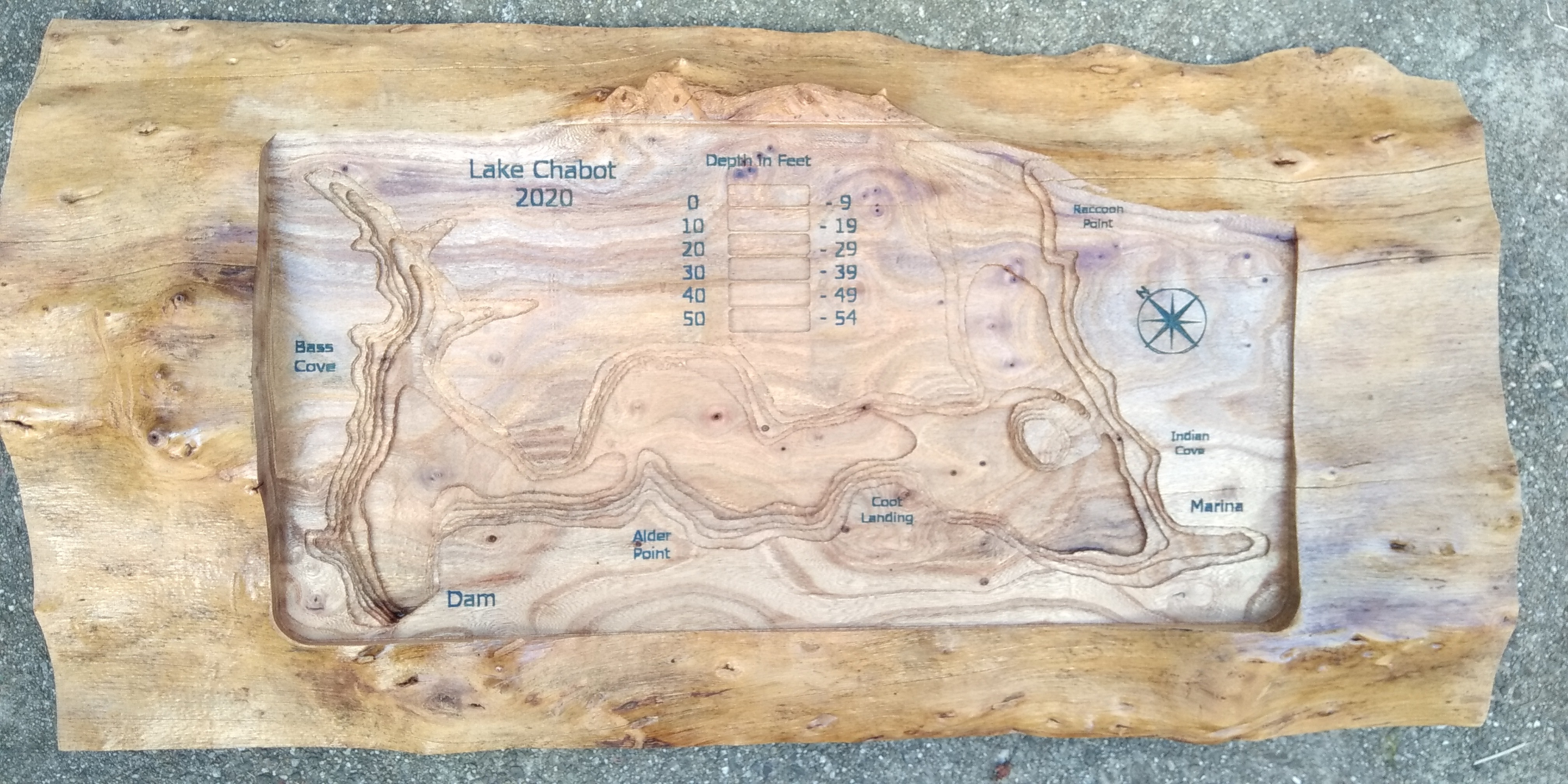
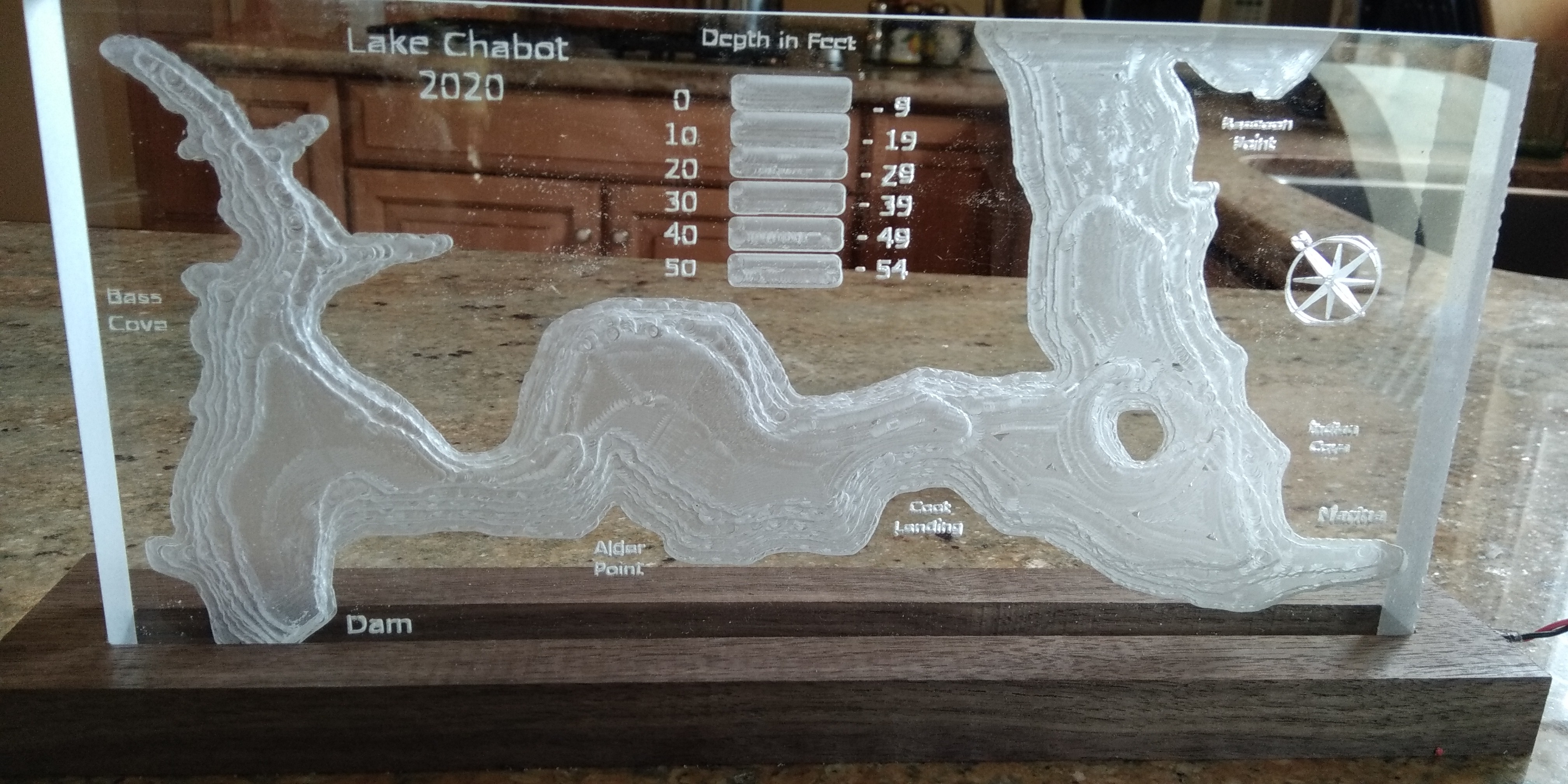
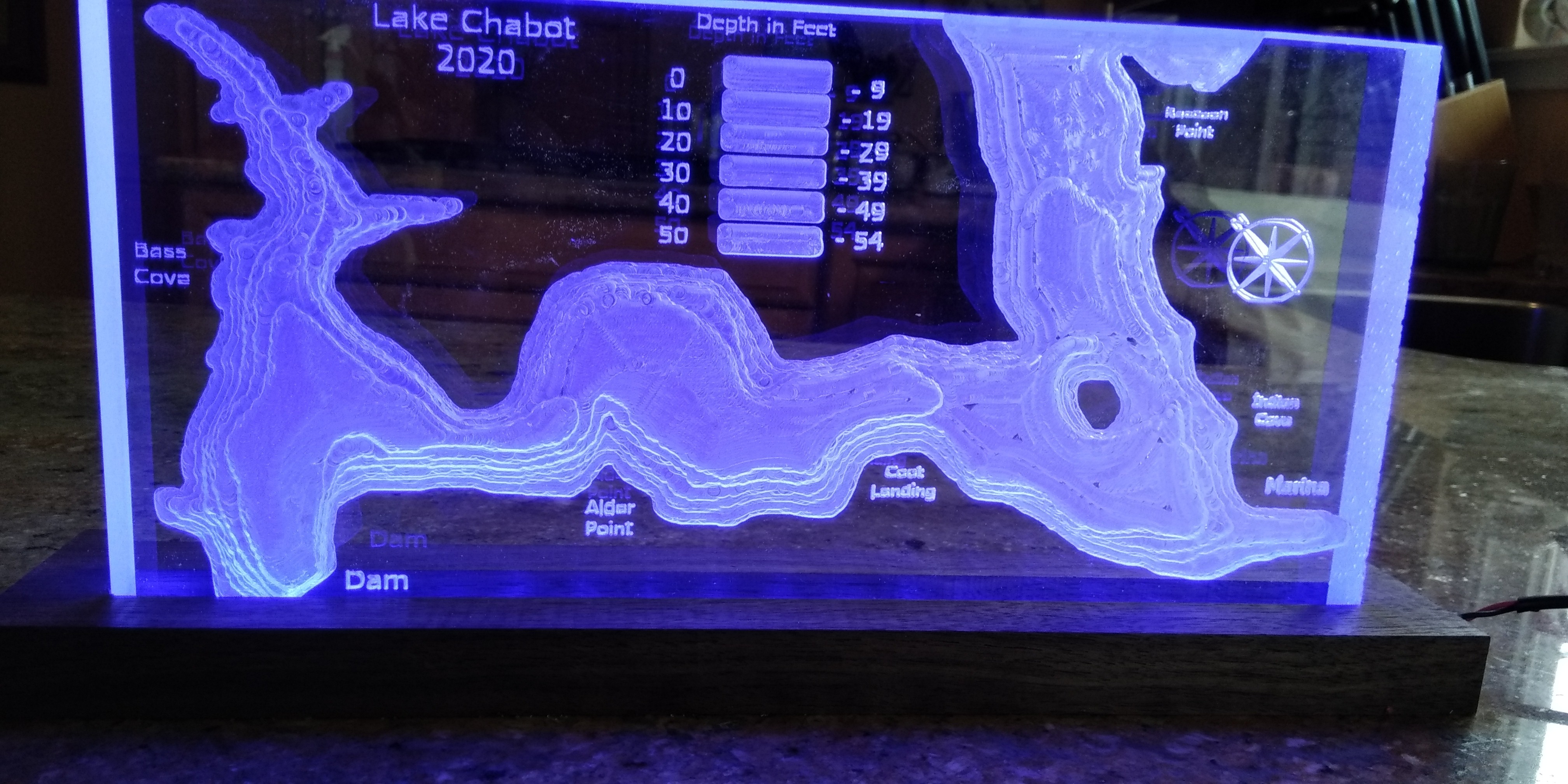
The CAM software I use is Vectric Aspire. The hows and whys of how one goes from grayscale image to G code for CNC don't fall in the scope of this Instructable. Suffice it to say that the software plots each shade of gray to be carved at a different depth. I added text to show major landmarks on the lake.
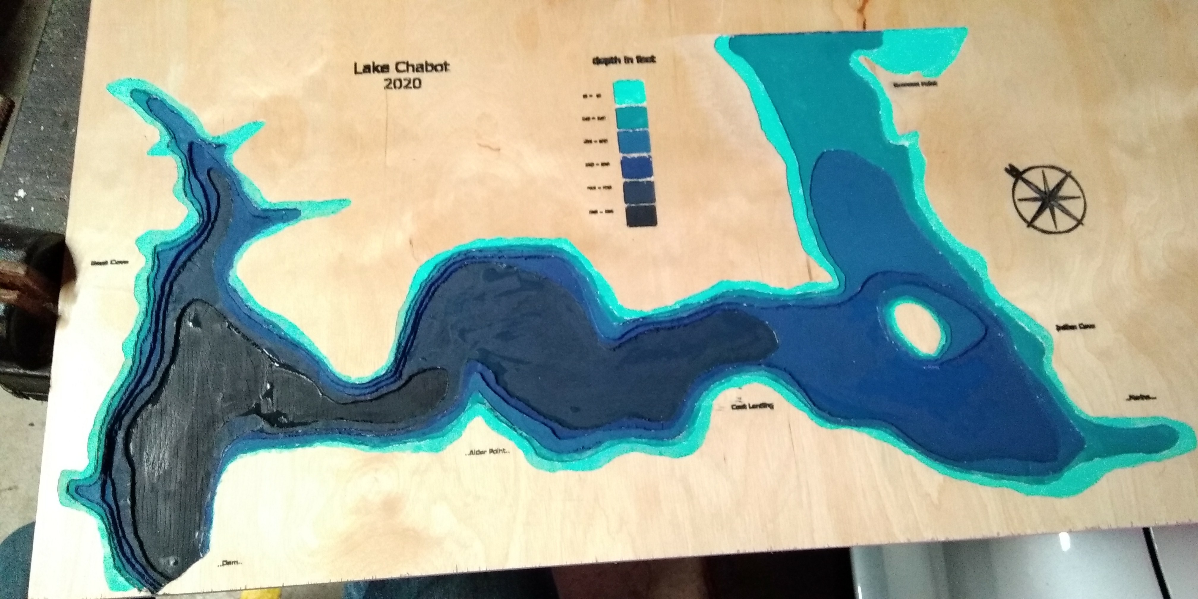
My first carving was on plywood and my notion was to paint each depth a different color. It came out rather funky in my opinion and took way too much work to mess with the paints. The next carving was on a log. Please see CNC Log Carving for my Instructable on this. It came out pretty well. I also did a carving on acrylic. The acrylic sits on a walnut base which is lit from the bottom.