Manga Reader ESP8266
.gif)


Greetings everyone,
So here's something fun: a MANGA READER made from scratch with custom PCBs and 3D printed parts.
The brain of this project is an ESP12F Module, which is an ESP8266-based WiFi Module connected to an ILI9225 LCD Screen to display black and white manga panels.
Manga is a style of Japanese comic books and graphic novels, typically aimed at a young adult or adult audience. It is characterized by its distinctive visual style, which often features exaggerated facial expressions, large eyes, and dynamic panel layouts. Manga covers a wide range of genres, including action, adventure, romance, comedy, drama, and more.
I've currently added a few pages of "Way of the House Husband" to the Manga reader device.
The ESP12F minimal setup is linked to a power management IC for power and an LCD screen, which is controlled by the ESP8266 board. The code contains sections of each slide/manga panel that are run in a sequential loop.
This instructables will explain how this entire concept came to be and how you can make it in a few simple steps, so let's get started.
Supplies
These were the materials used in this build-
- Custom PCB
- ESP12F Module
- ILI9225 2-inch LCD
- AMS1117
- M7 Diode SMA
- 10uF 1206 Package Capacitor
- 1uF 1206 Package Capacitor
- IP5303 Power Management IC
- 1uF 0805 Package Capacitors
- 10k 0805 Package Resistor
- 10k 0603 Package Resistor
- USB Micro Port
- SMD Button
- CON11 Header Pin for Adding LCD onto PCB
- M2 Screws
- Li-ion Cell 3.7V 2500mAh
- 3D Printed Body with LID
- NODEMCU
Concept/BREADBOARD SETUP
.gif)
.gif)

It all began with a straightforward Nodemcu and ILI9225 display setup that was being used to sequentially display a few images when the thought struck: what if we could display a series of comic panels—specifically, manga panels?
In order to test this, a few manga panels were downloaded and cropped to 176x220 pixels because the ILI9225 we're using comes in that size.
After resizing images, we run them through "Image to C Converter,"
It basically turns images into C code, which we include in the main code, which runs each image one by one in a loop.
We connect NODEMCU with the ILI9225 Display with the below pinout-
- VCC of display with Vin of NODEMCU
- GND to GND
- CLK to D5
- SDA to D7
- RS to D2
- RST to D4
- CS to D8
Next, we need to install this library in order to run the sketch.
Once everything is set up, we can upload the sketch to the NODEMCU Board to create a digital manga slide show!
Level 1 was this. In level 2, the ILI9225 display will be driven by a basic ESP12F setup, and battery functionality will be added to make the system portable and useful.
3D Design

In Fusion360, we first create a simple 75x95mm wide PCB model, then we create a rectangular enclosure around it that will support the PCB from the TOP side and contain a Li-ion cell from the bottom.
I exported the STL files for 3D printing the enclosure and its lid with Brown PLA with a 0.6mm nozzle and 0.2mm layer height.
For making the PCB, i used the model's DWG file which was later used in PCB Cad software to make board outline during the editing process.
STEP file of this model is attached if you want to make any edits.
PCB Design


This project's PCB design includes an ESP12F Minimal Setup connected to an ILI9225 Display.
The ESP12F's minimal setup consists of a few resistors pulling down GPIO15 to GND, pulling up the reset pin, EN pin, and GPIO0 to 3V.
An IP5303 IC setup, a power management IC that converts 3.7V of a lithium ion battery to 5V for charging a smartphone or powering any 5V device, is used to power the ESP setup.
The ESP8266 is a 3.3V device, so providing it with 5V will instantly fry the chip. To solve this problem, we added an AMS1117 3.3V Voltage Regulator setup that steps down 5V from the IP5303 to 3.3V to allow the ESP to function as intended.
Following the completion of the schematic, the board was created using the PCB Model DWG file and then sent to PCBWAY for manufacturing.
PCBWAY Service
.gif)
.gif)

After the PCB Design was completed, Gerber data was generated and then sent to PCBWAY for samples.
An order was placed for the PCBs with white soldermask and black silkscreen, as its looks pretty cool in general.
The PCBs were received within a week, and they were excellent, as expected.
Really love the quality of PCBs made by PCBWAY. There are other manufacturers available, but their service is always on another level.
check out PCBWay service for getting great PCB service at less cost.
PCB Assembly
.gif)
.gif)
.gif)
.gif)
.gif)
.gif)
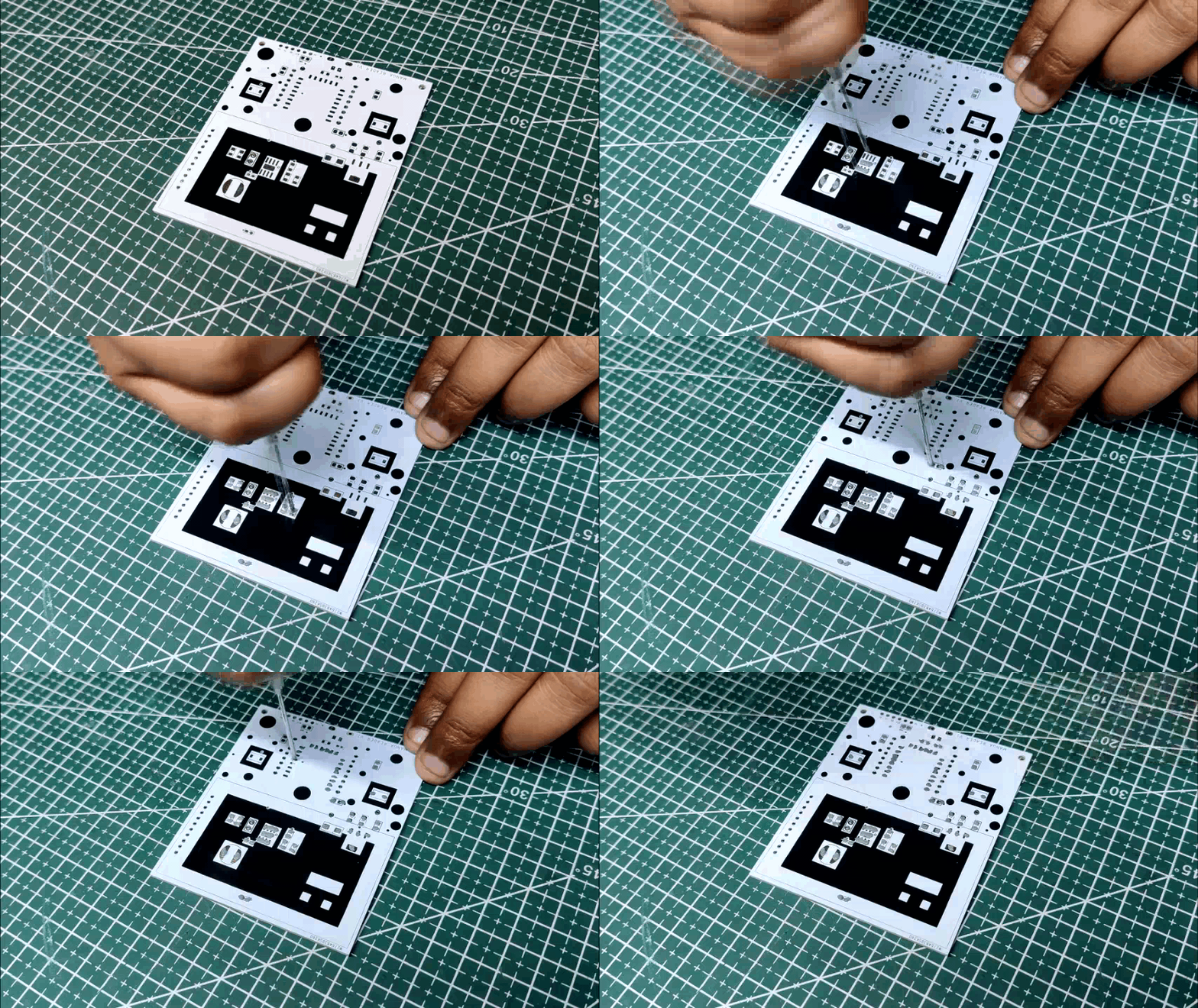
- Board Assembly Process begins by first adding solder paste to each component pad one by one.
- Next, using a tweezer, we pick and position each SMD component in its designated location.
- Following that, we carefully lifted the entire circuit board and set it down on the Mini SMT Hotplate, which heats the PCB from below up to the solder paste melting temperature. As soon as the PCB reaches that temperature, the solder paste melts, and all the components are connected to their pads.
- Next, we add the CON11 header pin to its pad and solder it using a regular soldering iron.
- The board assembly process is then finished by soldering the USB Micro port's pads to the PCB.
ILI9225 Display
.gif)
We are using the 2.0 Inch TFT Display which is powered by the ILI9225 Driver.
The ILI9225 is a driver IC (integrated circuit) used for controlling small to medium-sized TFT LCD (thin-film transistor liquid crystal display) panels. It supports displays with resolutions up to 176x220 pixels and 18-bit (262,144 colors) color depth.
In summary, the ILI9225 is a versatile and widely used driver IC for small to medium-sized TFT LCD displays, and it offers a range of display modes and features for controlling the display.
This display's very low refresh rate makes it unsuitable for running any project involving animation; instead, use the ILI9341 Display or a similar LCD if you want to run gifs or videos without stuttering.
Edit Done in PCB
.gif)
We made some PCB changes prior to flashing, including rewiring the LCD's pins with an ESP12F module.
We disconnected the traces below and added silver copper wire to connect the LCD pins to the ESP8266's I/O pins because some connections were made during the preparation of the schematic in a way that prevented the LCD from functioning.
- We cut the trace that connected CS to GND and connected it to GPIO15.
- We cut the trace from RST's connection to GPIO15 and connected it to GPIO2.
- RS was connected to SDA; we cut that connection, and then connected RS to GPIO4.
- We cut the traces connecting SDA to GPIO4 and added it to GPIO13.
- We cut the trace from CLK's connection to GPIO5 and added it to GPIO14.
The wiring is now correct after the aforementioned modifications, so we can test this board and flash the ESP12F with main code.
Programming the ESP12F With NODEMCU
.gif)
You might not be aware that any ESP board can be programmed using the NODEMCU Board.
By taking a NODEMCU board and connecting a jumper with its GND Pin and EN Pin, which puts the onboard ESP8266 of the NODEMCU into sleep mode, we may utilize the NODEMCU to program the external ESP12F module.
This enables us to connect an external ESP Board to NODEMCU; so essentially, we are turning off the ESP board on the NODEMCU and connecting a second ESP Board to a few of its pins.
You can read the article below for additional information about this process.
Power Source
.gif)
.gif)
We are using a 3.7V 2500mAh Lithium Ion cell as the power source, and we are connecting its positive and negative terminals to the IP5303 setup's battery con2 from the bottom side.
When we press the IP5303 IC's button, the entire setup comes on, and the manga reader starts to function and display a panel of manga.
The project is now finished; all that is left to do is incorporate the circuit into the 3D Enclosure.
Final Assembly
.gif)
.gif)
.gif)
.gif)
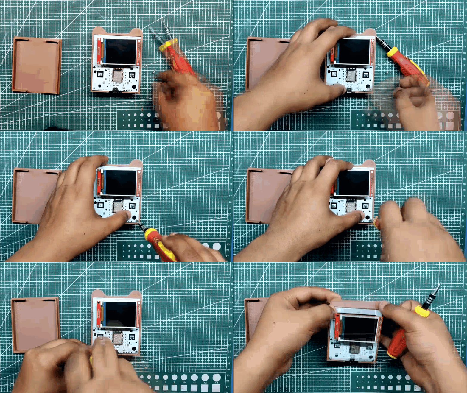
- The battery is first inserted into the enclosure from the top side before the PCB is added.
- Next, we insert two M2 screws to hold the PCB in place.
- The device is then turned, and hot glue is added to the lithium cell to hold it in place.
- Finally, a lid is added to the back of the enclosure and fastened with four M2 screws to complete the assembly process.
RESULT

.gif)
The Result of this built is a pocket manga reader that continuously loops through panels of manga; yes, the image quality is not the best and it required a tedious process of converting each image into C Code and then combining that code to make a single long code that is flashed into ESP8266 board.
The best thing about this device is its extreme overkillness and how we were able to create a display device that could be used for many XYZ things in addition to just displaying comics. This device is essentially a portable display with a WiFi module that can be used to do all sorts of things, from gathering weather information from the internet to getting the time, it has numerous uses.
Version 2 of this project will have a larger ILI9341 display and a slim form factor because the previous version's use of a li-ion cell, which has an 18mm diameter, made the device's body thicker. By switching to a lipo cell, however, we were able to make the device slightly slimmer.
Do leave a comment if you need any help regarding this project.
This is it for today folks.
Thanks PCBWAY for supporting this project, you guys can check them out if you need great PCB and stencil service for less cost and great quality.
And I'll be back with a new project pretty soon!