Making Your Own Metronome
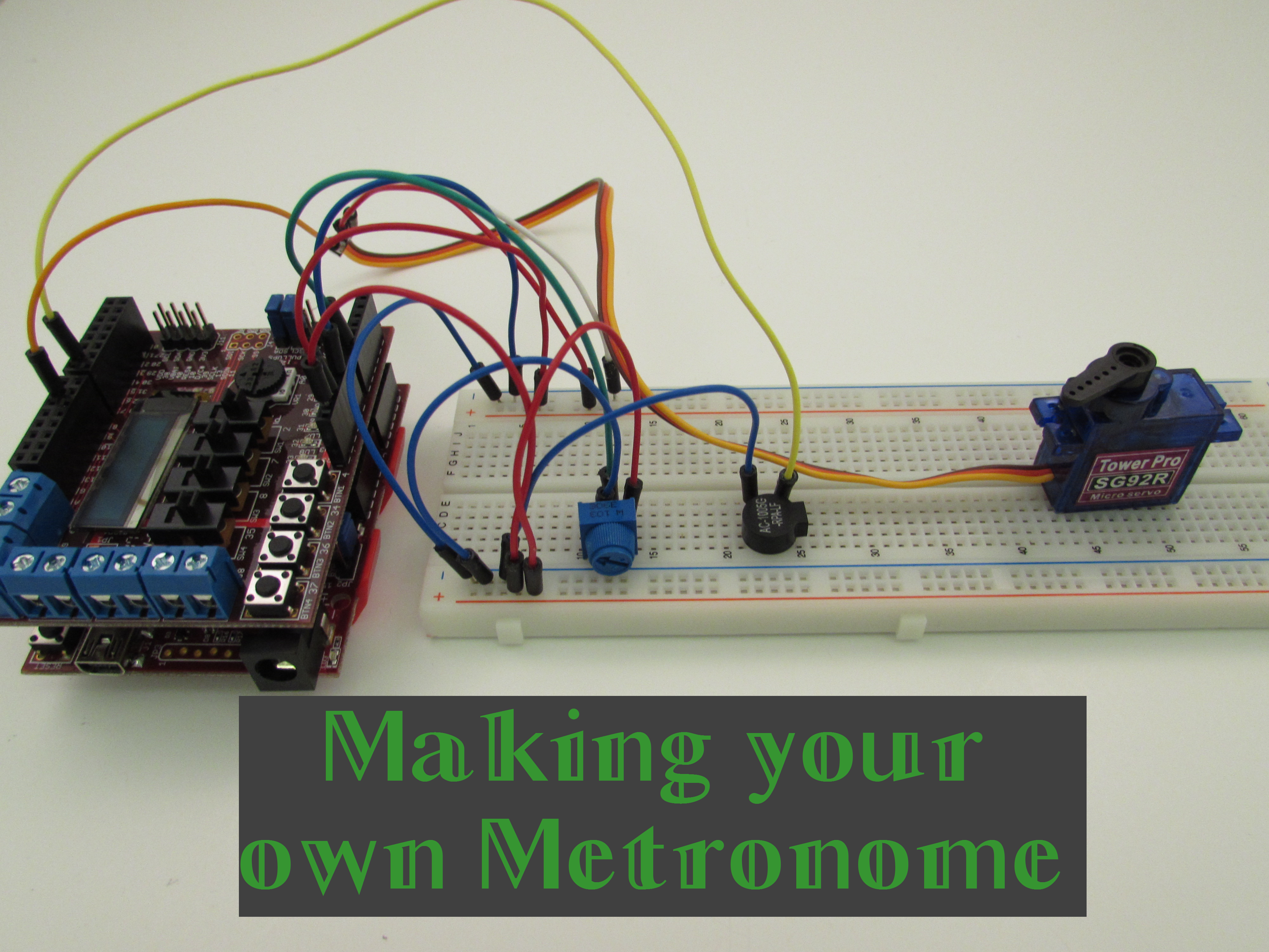
For those of you out there that have a soft spot for playing music, this instructable is for you. As the title suggests, we will be creating our own adjustable metronome with parts available from Digilent Inc.
We will be primarily focusing on setting up the circuit with a general overview on how some of the components operate without going into gross amounts of detail. Code to operate our circuit will also be provided.
What We Need
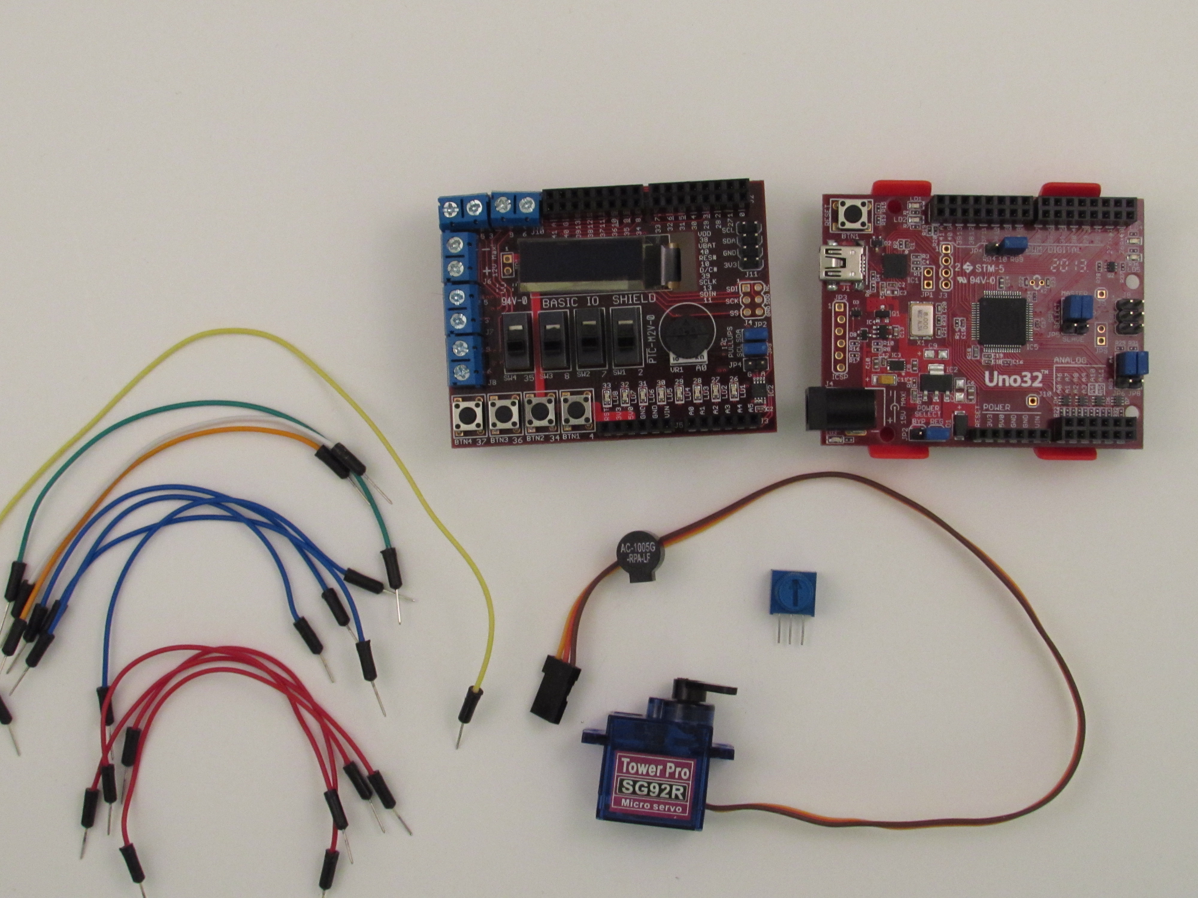
Naturally, we will be needing a few parts before we can get started building our metronome.
What we will be using is:
- AC-1005G-RPA-LF speaker buzzer
- 10k ohm potentiometer
- Tower Pro SG92R servo motor
- Breadboard (not pictured)
- Breadboard jumper wires
- chipKIT Uno32
- chipKIT Basic I/O Shield
All of these components, except for the chipKIT Uno32 and the Basic I/O Shield, are included in Digilent's chipKIT Starter Kit. The chipKIT Uno32 and the Basic I/O Shield are also available from Digilent Inc. It may be noted that the Basic I/O Shield is used for a much-improved visualization of the beats-per-minute that the metronome is currently running at, but is not crucial in terms of driving the metronome. However, we will presume that we are using the Basic I/O Shield in this instructable.
Assembling the Circuit- Initial Setup
Plug in the Basic I/O Shield on top of Uno32. Because the Basic I/O Shield and the Uno32 have the same form factor, the pins on the Basic I/O Shield are in the same location that they are on Uno32, so pins will fit quite nicely.
Then connect one of the ground pins on the Basic I/O Shield (labeled "GND") and connect it to the negative bus strip on the breadboard. Connect this negative bus strip with another negative bus strip. Now, connect the 3.3V pin on the Basic I/O Shield to one of the power bus strips and then connect the 5V pin on the Basic I/O Shield to different power bus strip.
Assembling the Circuit- the Servo Motor
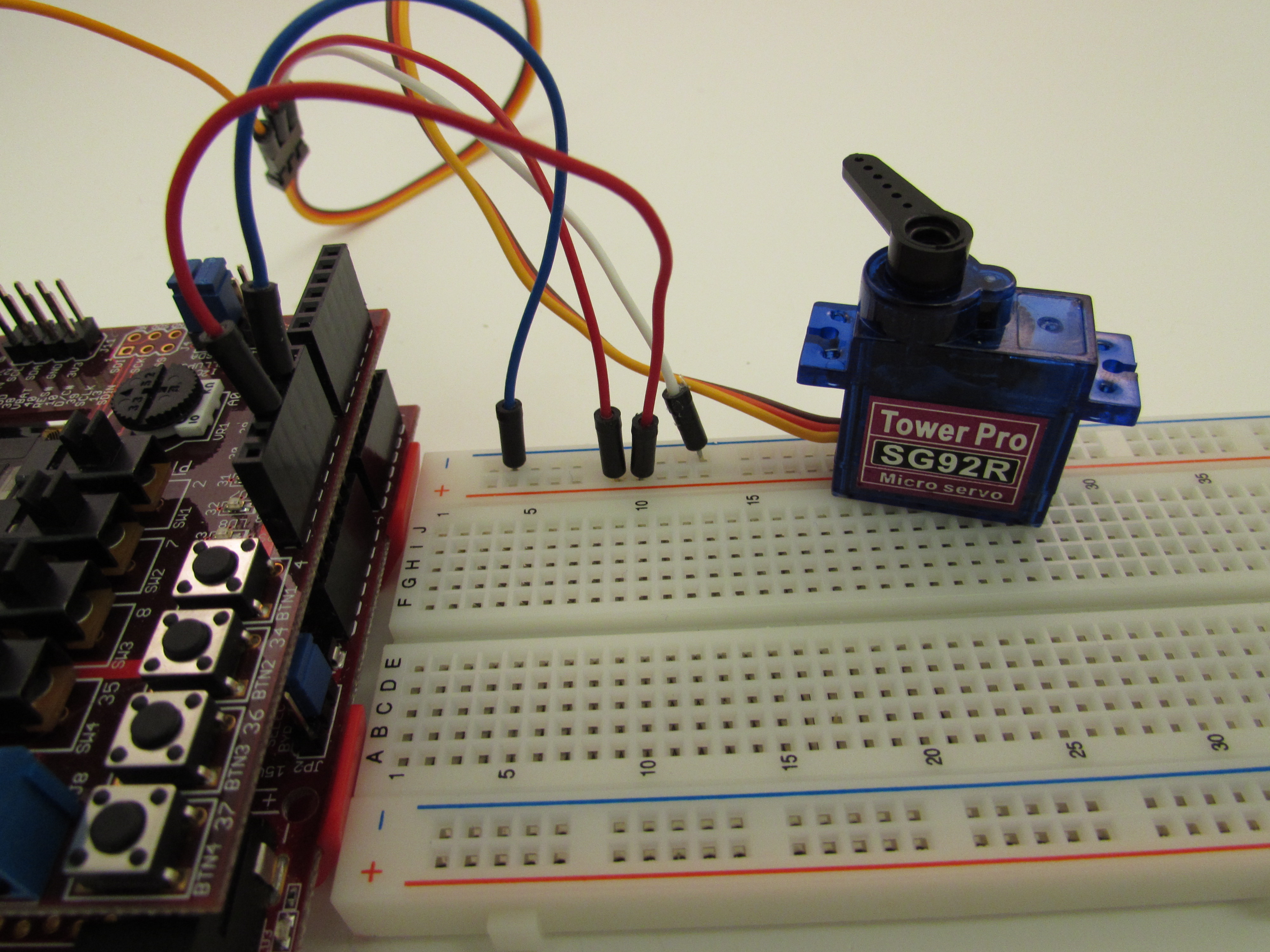
The servo motor is the key visual component for our metronome. For those of you that may not be familiar with servo motors, they are a type of motor that has precise control over where the servo arm is rotated. This is in contrast to a DC motor, which does not have precise control over the amount of rotation but can spin much much faster than servo motors.
Our particular servo motor is limited in its rotation angle between 0 and 180 degrees; perfect for a metronome. You will notice that our servo motor has three wires coming out of it; these are the ground wire (brown), the power supply wire (red-orange), and the control wire (yellow). Taking advantage of our numerous breadboard jumper wires, connect the ground wire to one of the negative bus strips on the breadboard and connect the power supply wire to the 5V bus strip.
Because our servo motor requires a pulse width modulation (PWM) signal, connect the control wire to one of the digital pins on the Basic I/O Shield capable of PWM; these are pins 3, 5, 6, or 9. In this particular circuit, we will be using pin 9. If you don't know what PWM is, that's okay. The servo library in our code will take care of the details for us.
Assembling the Circuit- the Potentiometer
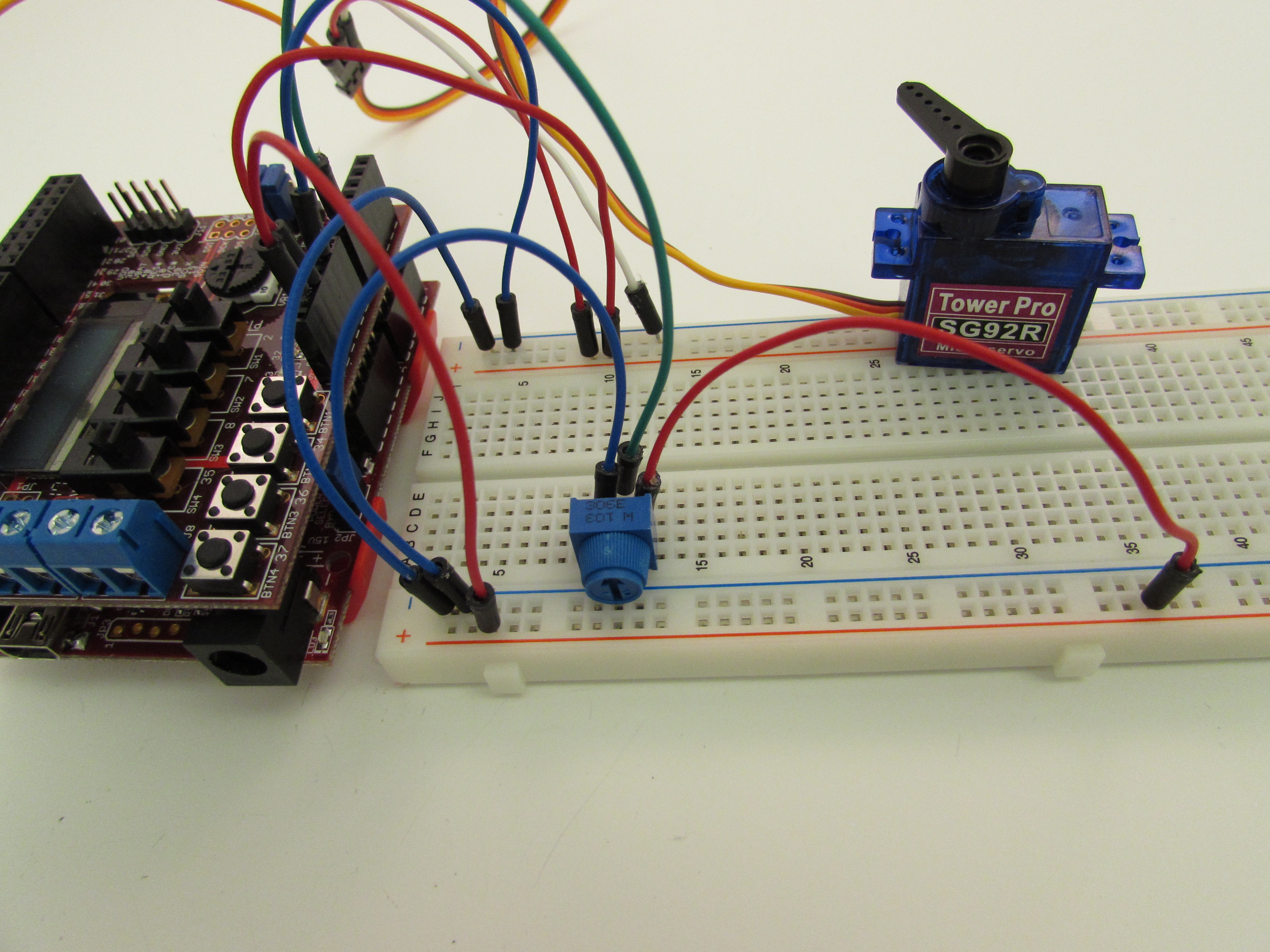
The potentiometer is going to be controlling how fast our metronome is moving. As a sneak preview, we will be adjusting our metronome speed between 50 beats-per-minute (bpm) and 200 bpm. The upper limit of 200 bpm is because our servo arm, according to Tower Pro's website, moves at a maximum rate of 60 degrees in every 0.1 seconds. A bit of math can be done to see this is equivalent to 200 bpm. The lower bound of 50 bpm is actually arbitrary, but 50 bpm is slower than a ticking clock, so any slower of a tempo would mean you most likely writing a dirge for your own funeral, which I imagine would not be terribly fun. Hence the lower bound of 50 bpm.
To wire up the potentiometer, first place it somewhere on the breadboard. Then with the dial portion facing towards you, connect the right most leg to the 3.3V bus line and wire the left most leg to a negative bus strip. The middle leg should be connected to an analog pin on the Basic I/O Shield, such as A0. This will be so that we can read how much resistance to current flow our potentiometer is providing, which in turn will dictate how fast our metronome will rotate between 0 and 180 degrees.
It is interesting to note that the servo arm itself, will always move at the same speed: 60 degrees for every 0.1 seconds. What we will be doing in our code to get the variation in tempo is adjusting how much the servo arm is to rotate. For example, if we tell the servo arm to rotate only 30 degrees in every 0.1 seconds, it will still move to those 30 degree increments at the 60 degree/ 0.1 second rate. But, because it will get to its destination in half the time allotted, the servo will stop moving for 0.05 seconds until it receives the next command to move another 30 degrees. This technique will allow us to achieve slower tempos and give the appearance that the servo arm is "moving slower".
Assembling the Circuit- the Speaker Buzzer
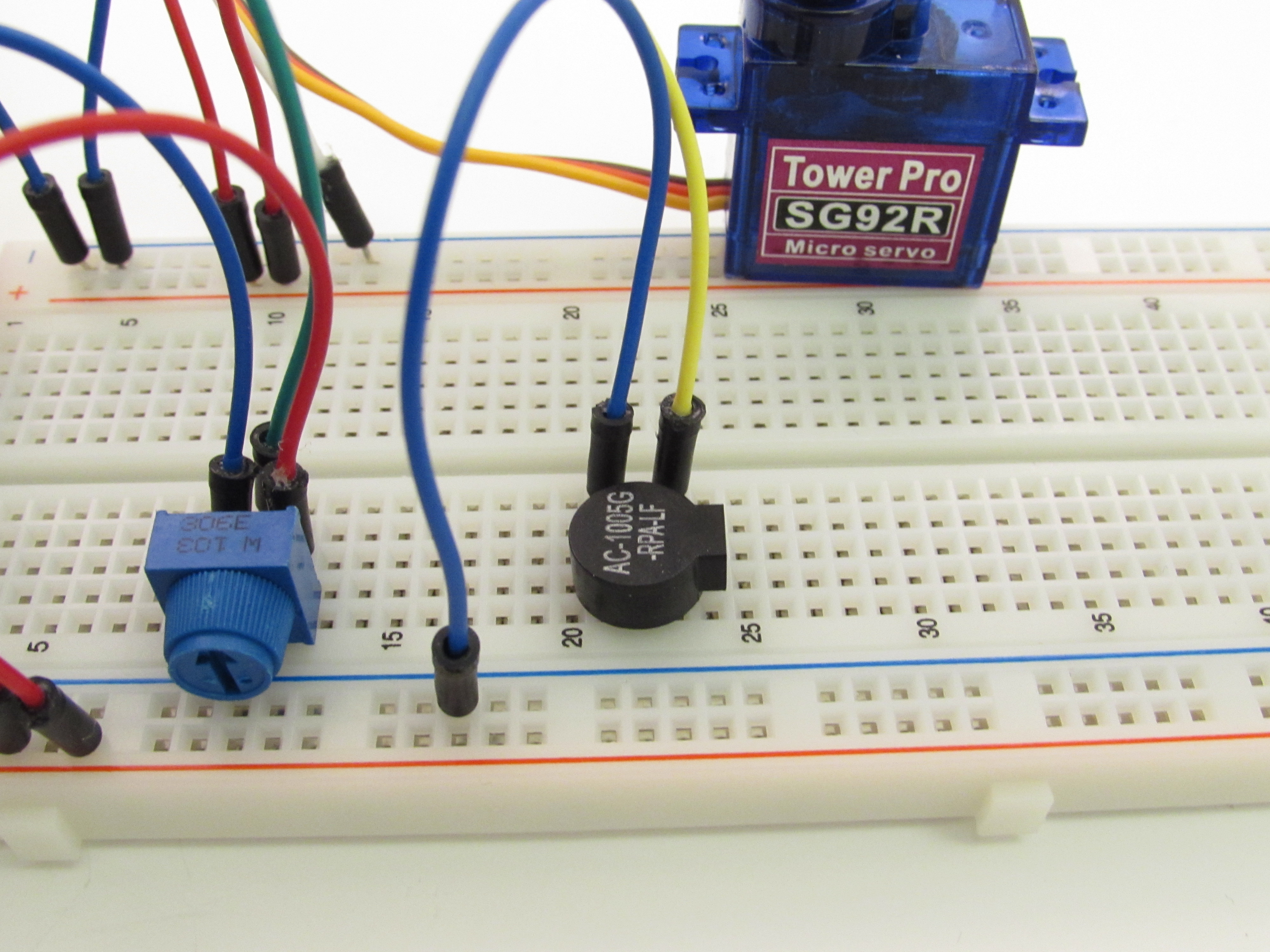
The speaker buzzer is what will create the traditional "tick" that is associated with metronomes. Speaker buzzers work because of the piezoelectric element inside of them. Piezoelectric elements, for those of you who may not know, are a type of material that changes its shape when an electric current is applied (or conversely for some piezoelectrics, produce an electric current when pressure is applied).
For speakers, this phenomenon can be taken advantage of by turning the current to the speaker buzzer on and off at a various rates to produce vibration of the element in the buzzer and thus produce sounds of different frequencies. According to the buzzer frequency response graph, this buzzer is the loudest when vibrating at a frequency between 2500 Hz and 2750 Hz. However, we do not want to have the servo motor visibly stopping while the speaker is buzzing at every 0 and 180 degree mark, so we will end up only allowing enough time for the speaker to produce an audible "click" which is more appropriate for a metronome anyway.
To wire the speaker, place the speaker buzzer on the breadboard in a similar fashion to the way you see it in the picture; you may have to bend the legs slightly to get it to fit in the breadboard. Then connect the leg that is farthest away from the "speaker mouth" to one of the negative bus strips. Connect the leg that is closest to the "speaker mouth" to one of the PWM capable pins on the Basic I/O Shield. We will be using pin 6 in this example.
For those of you that are familiar with speakers may know that we don't strictly need PWM to drive the speaker. The reason we are using one of those pins on the Basic I/O Shield is because all of the other digital pins that are not capable of PWM are directly tied to one of the other items on the shield, such as a button or switch, so it's simply easier to directly connect to the speaker. Anybody interested in what the other pins on the I/O Shield are connected to can check out the pinout table for the Basic I/O Shield.
Prepping for the Code
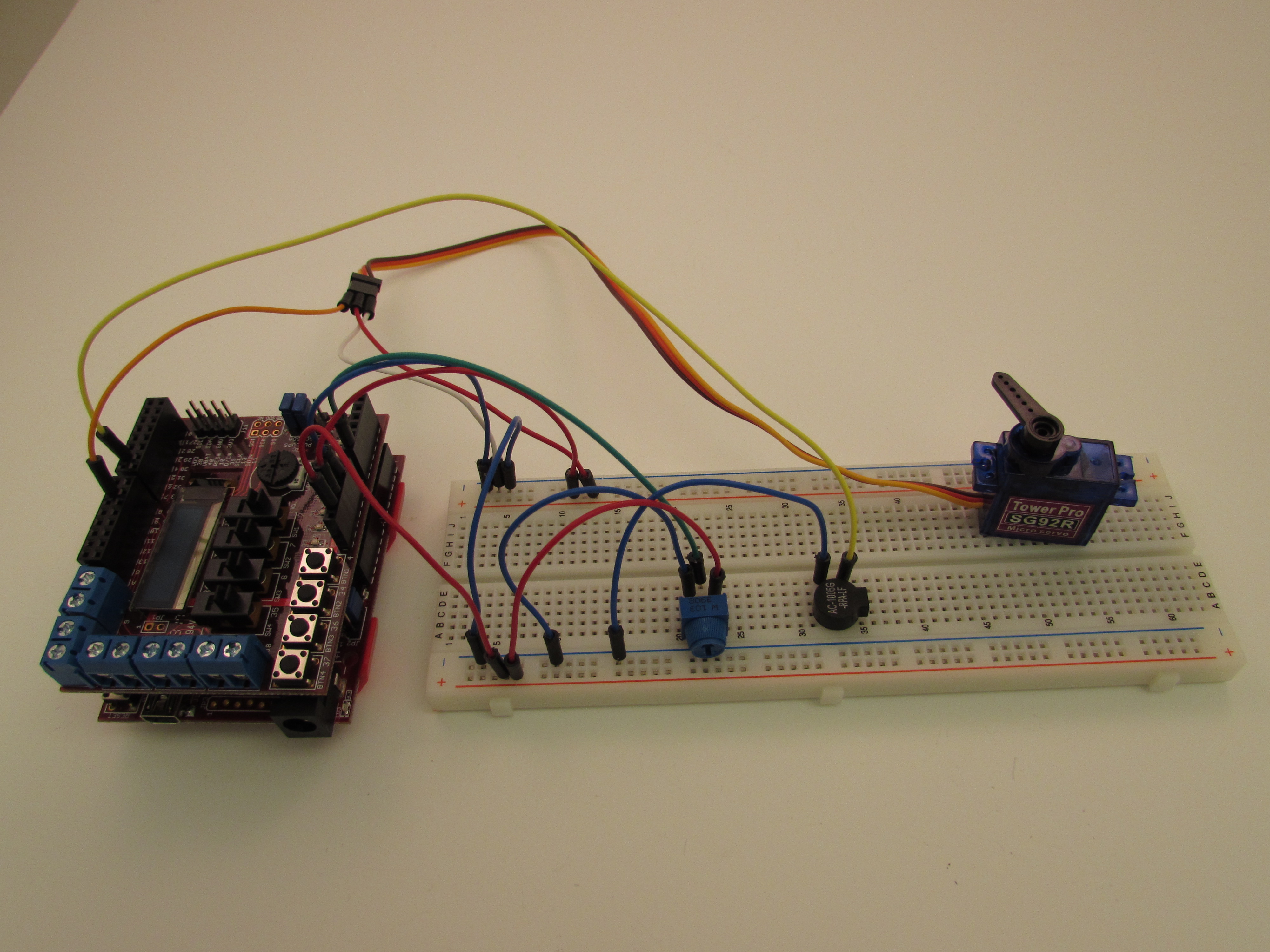
The final circuit should look similar (doesn't have to be exactly the same) to the one shown in the picture above.
To get the metronome up and running we need to have code to tell each component what to do and when to do it. If you do not have the free mpide software to compile and load the code onto the Uno32 you can get it here. Specific instructions on how to download the software are available on the Digilent Learn site. If you are unfamiliar with how code is utilized within mpide feel free to check out the link here.
The Code
As you can see just below this step, there is a text file of the code used to run the metronome. I won't go any great detail here on how the code works or was set up, but I will briefly explain where some of the math came from for changing the tempo since that is arguably one of the most important parts that makes this circuit a metronome.
Recall that the servo arm moves a maximum rate of 60 degrees for every 0.1 seconds. This is equivalent to 6 degrees for every 10 milliseconds and the same as 200 bpm. We (arbitrarily) wanted our lower bound to be at 50 bpm which is 1/4 the pace of 200 bpm. Because 6 degrees/ 10 milliseconds is our maximum rate, this means that our minimum rate must be 1/4 of the max rate, or 1.5 degrees/ 10 milliseconds.
Thus, our span between our upper and lower bounds is only 4.5 degrees. We want to adjust the rate in this range through the potentiometer. The analog reading of the potentiometer output can range from 0 (essentially no current flowing through the potentiometer) and 1023 (the maximum amount of current flowing through the potentiometer.
So, what we want to do is create a linear equation of the form y=mx+b to figure out how much of an angle change the servo should make based on how much current is flowing through the potentiometer. 'y' will be the angle change, 'm' is the slope or how much affect the potentiometer has on the angle change, 'x' is the value of the potentiometer, and 'b' is y-intercept or a type of correction factor for the angle change.
We can get our slope by dividing the span of the angle change, 4.5, by the maximum value that the potentiometer can have, 1023. This gets us the "scalar" value you see in the code. We can then multiply our scalar value by whatever the current potentiometer value is and add our correction factor which is the 1.5 degree lower bound. This concisely tells us how much of an angle (or tempo) change that the servo should make based on where the potentiometer is positioned.
Downloads
Operation
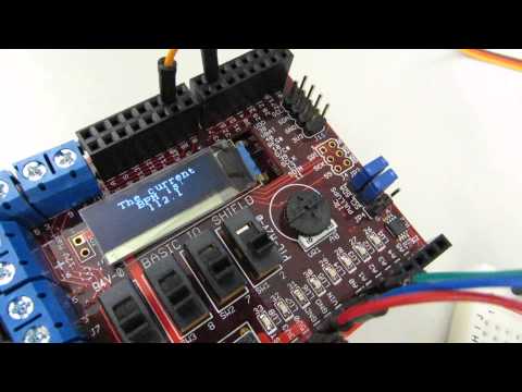
Check out the video to see a live demonstration of the metronome at work! I know the little speaker is hard to hear on the video with the servo motor going, but I promise it's there.
Feel free to ask any questions that you might have and have fun!