Making a Wheel in Inventor
by toa697 in Design > Digital Graphics
1745 Views, 0 Favorites, 0 Comments
Making a Wheel in Inventor
This is going to be a simple project for making a wheel in inventor.
Making a New Project
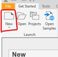
First things first is to click on the new project tab.
Choosing Part Format
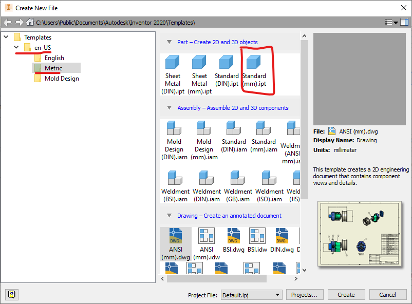
For this project we will be using the default mm part format.
Starting a Sketch
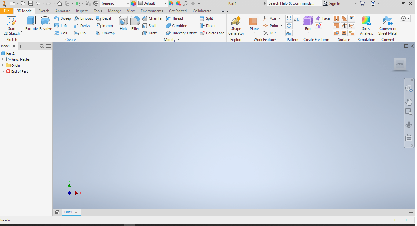
You can open a new sketch by clicking on the sketch button in the top left corner, or by pressing the 's' key.
Choosing the Plane
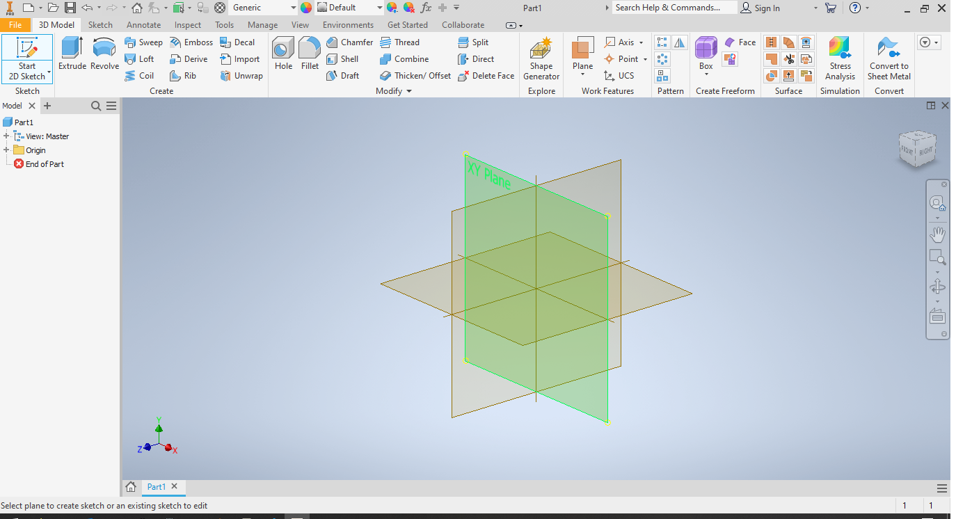
Choose the XY plane for this project, as highlighted in the image.
First Guide Line
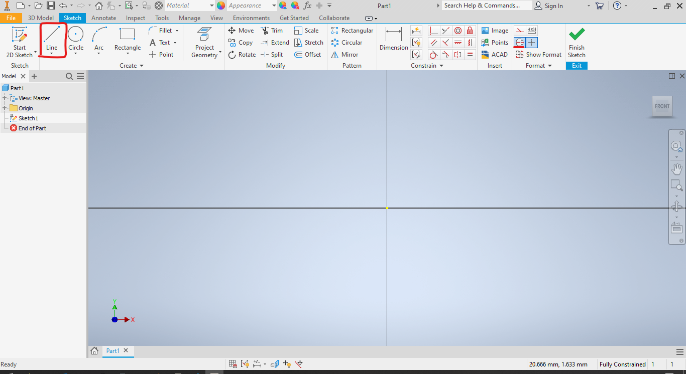
Select the line tool (highlighted top left) and the centerline option (highlighted top right).
Drawing the Guideline
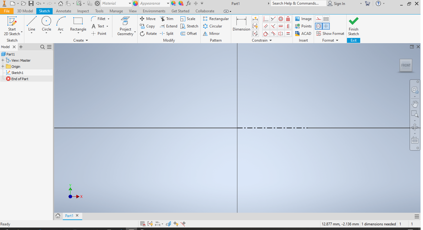
Draw the guideline, by first clicking on the centerpoint of the intersecting lines, and then across, still laying along one of the intersecting lines. After drawing this line, press escape to prevent any more lines being drawn.
Outlining the Object
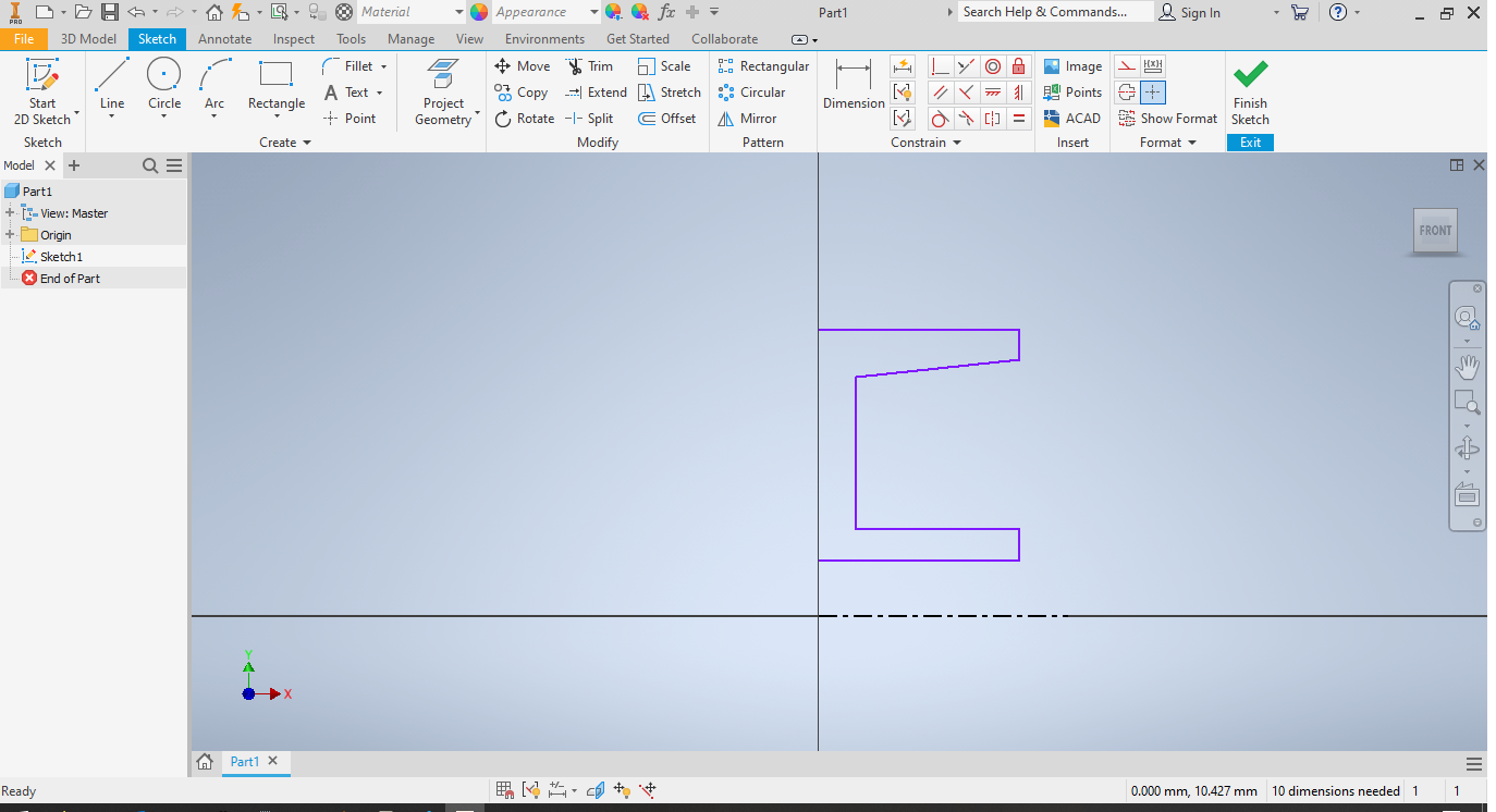
Next, click on the centerline toggle again to disable it. Now draw, starting at the vertical line, making sure that each right angle is snapped into place, and that the diagonal line is not snapped into place.
Exact sizes are not important right now, as they will be defined in a later step.
Second Guide Line
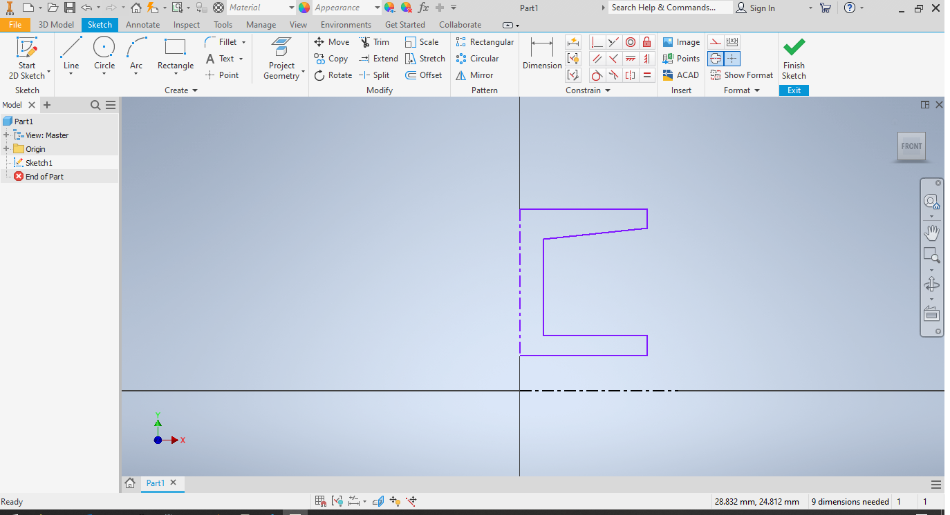
Then enable the centerline feature again to draw another guide line, this time down the middle of the sketch.
Select Mirror Tool
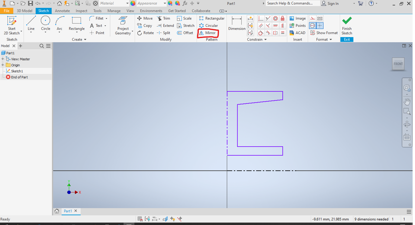
Click on the highlighted option for mirroring.
Select Mirrored Components
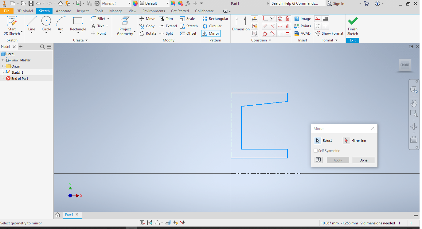
Click on the highlighted components, to select them as the ones that will be mirrored.
Select Mirror Line
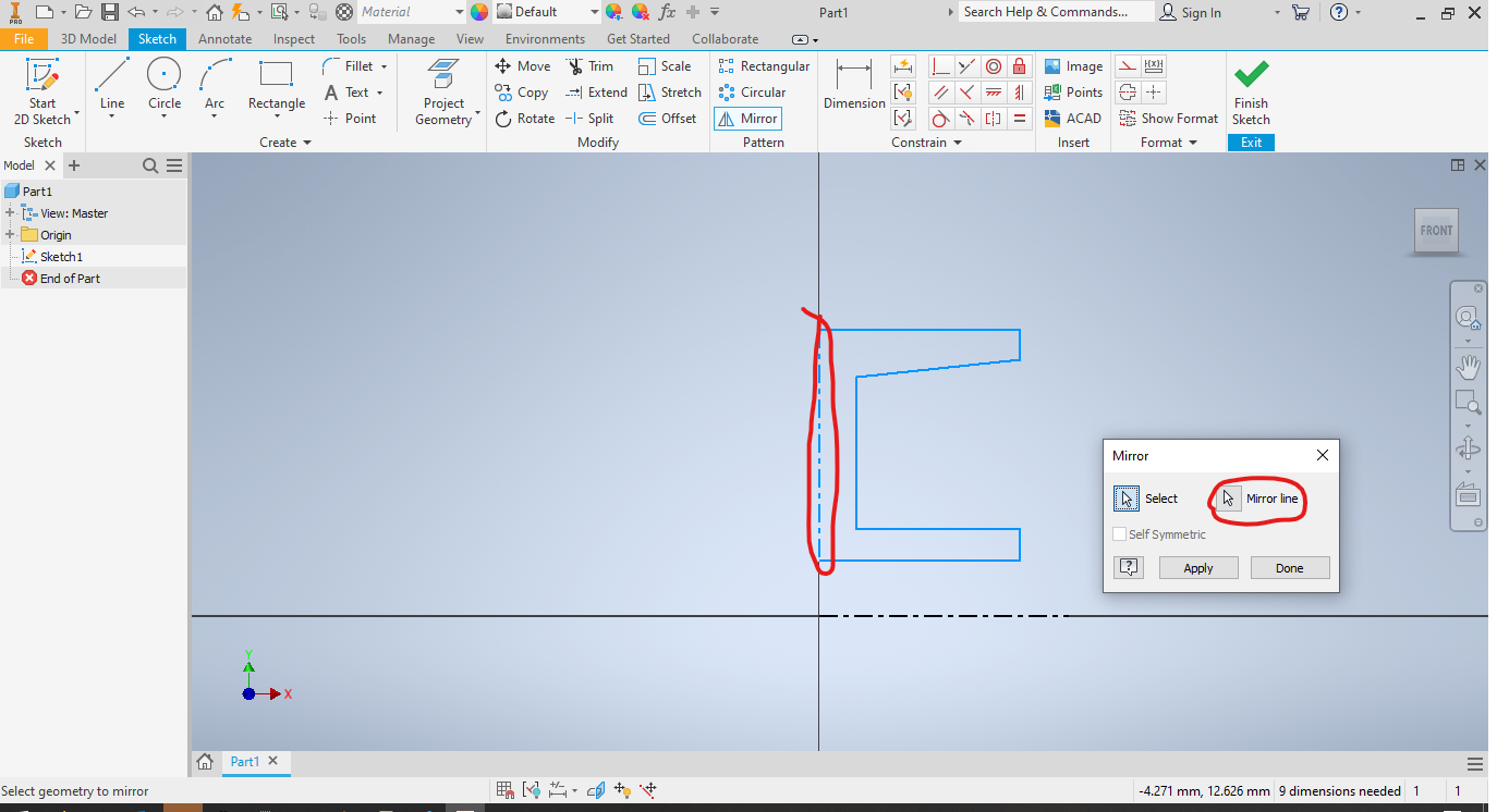
Click the highlighted mirror line button, and then select the guide line made earlier.
After this click on the apply button, to apply the operation.
Dimension Tool
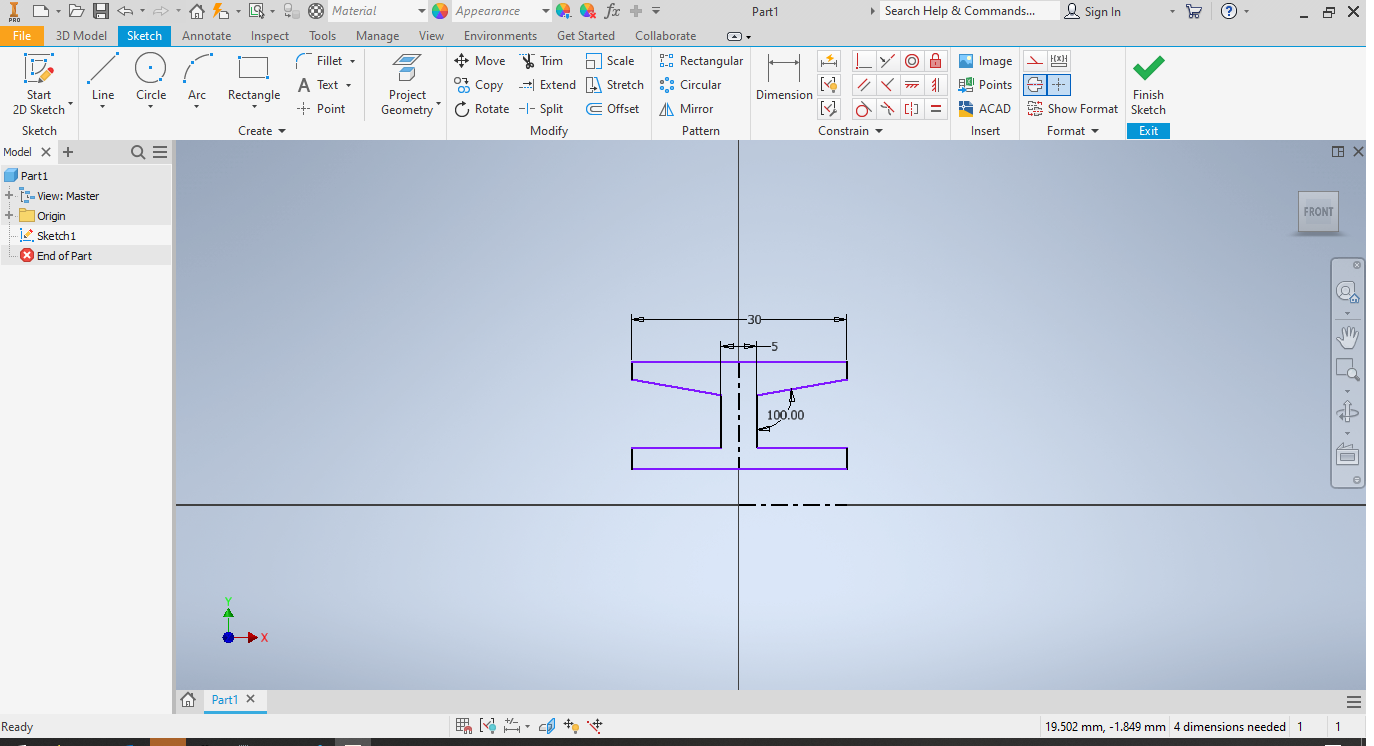
click on the dimension tool, and use it to set the following distances.
This can be done by clicking on two different lines that you want to make a measurement between.
Diameter Dimensions
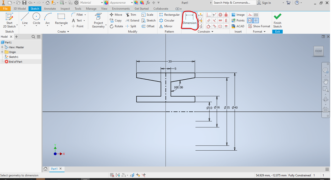
A different kind of dimension is made when one of the lines is a centerline. use it to create the following dimensions.
Alignment
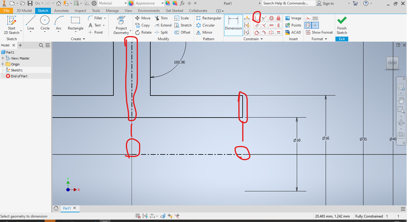
finish up the needed dimensions by using the highlighted coincident tool between the highligted set of lines and points.
Finished Sketch
press the 's' key to finish the sketch, it should now look like this.
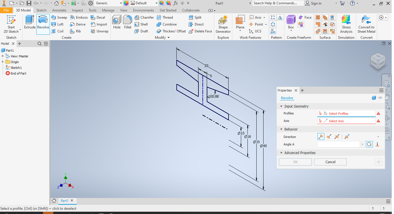
Revolve
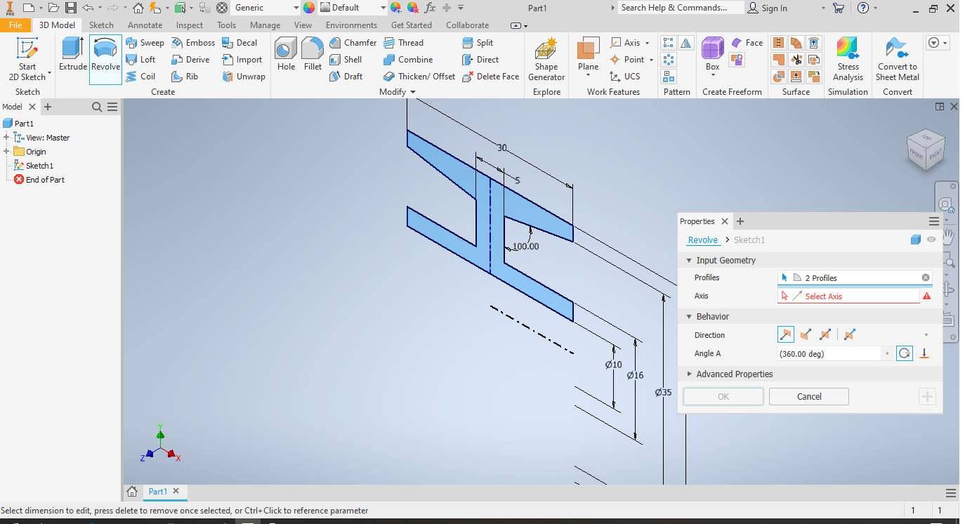
Select the revolve operation and select the highlighed blue sections.
Select the Axis of Rotation
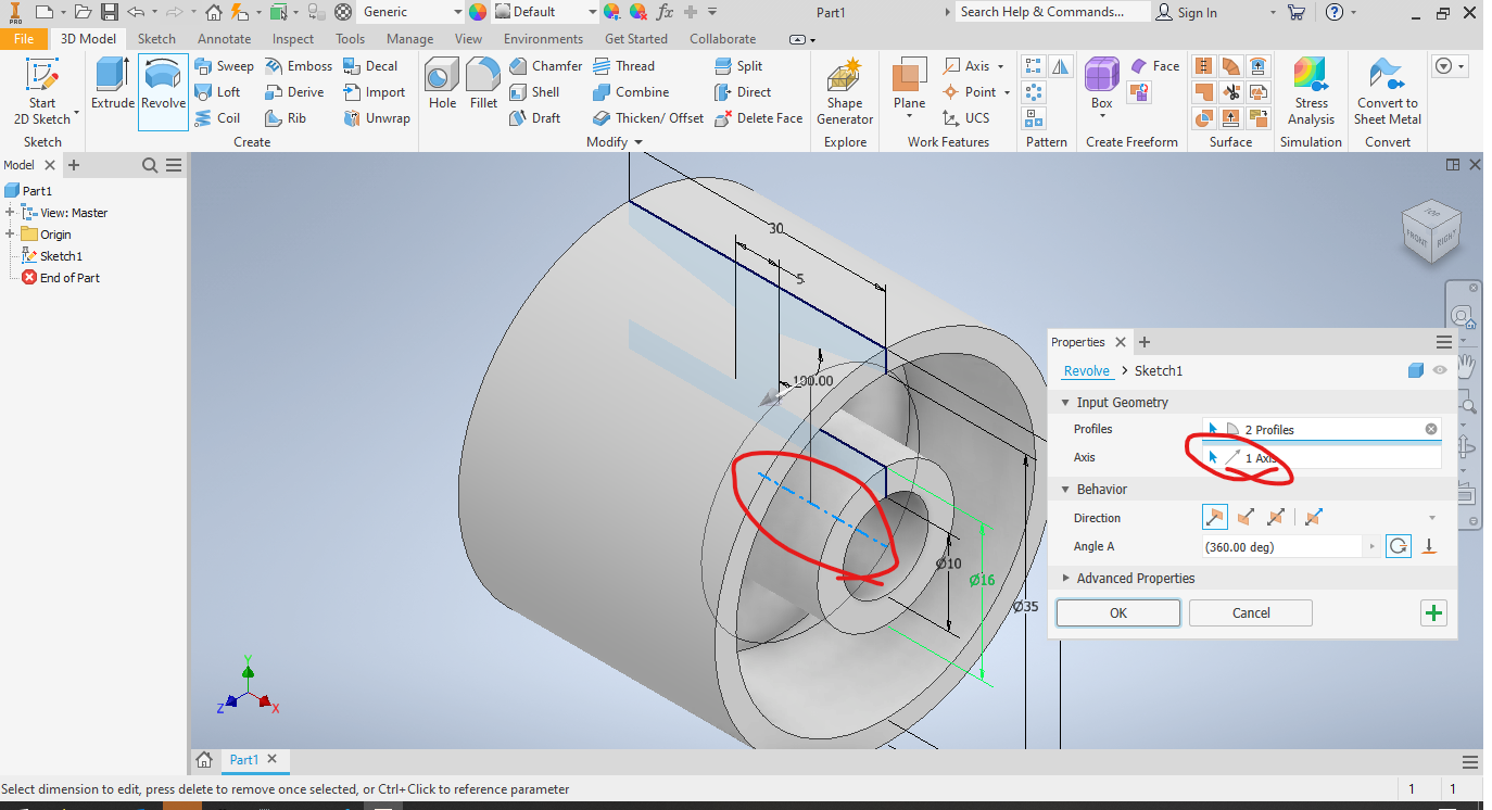
Click on the highlighed option, and the centerline from earlier, this will complete the revolve.
Finish
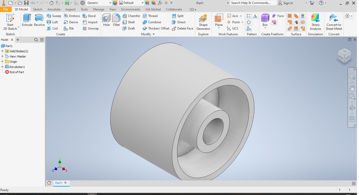
click OK and this will complete your wheel.
Complete!
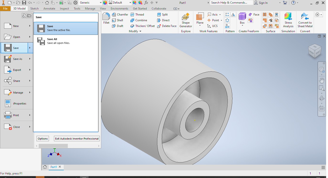
Simply Save your project and you will be done!