Making a Virtual Drawing With Software
by moberlyi in Workshop > Organizing
466 Views, 0 Favorites, 0 Comments
Making a Virtual Drawing With Software
.png)
This is for beginners (otherwise more attention to detail would have been incorporated).
I am using the example of a Wheels Base Plate.
Step One
.png)
Begin by loading up your Inventor Software.
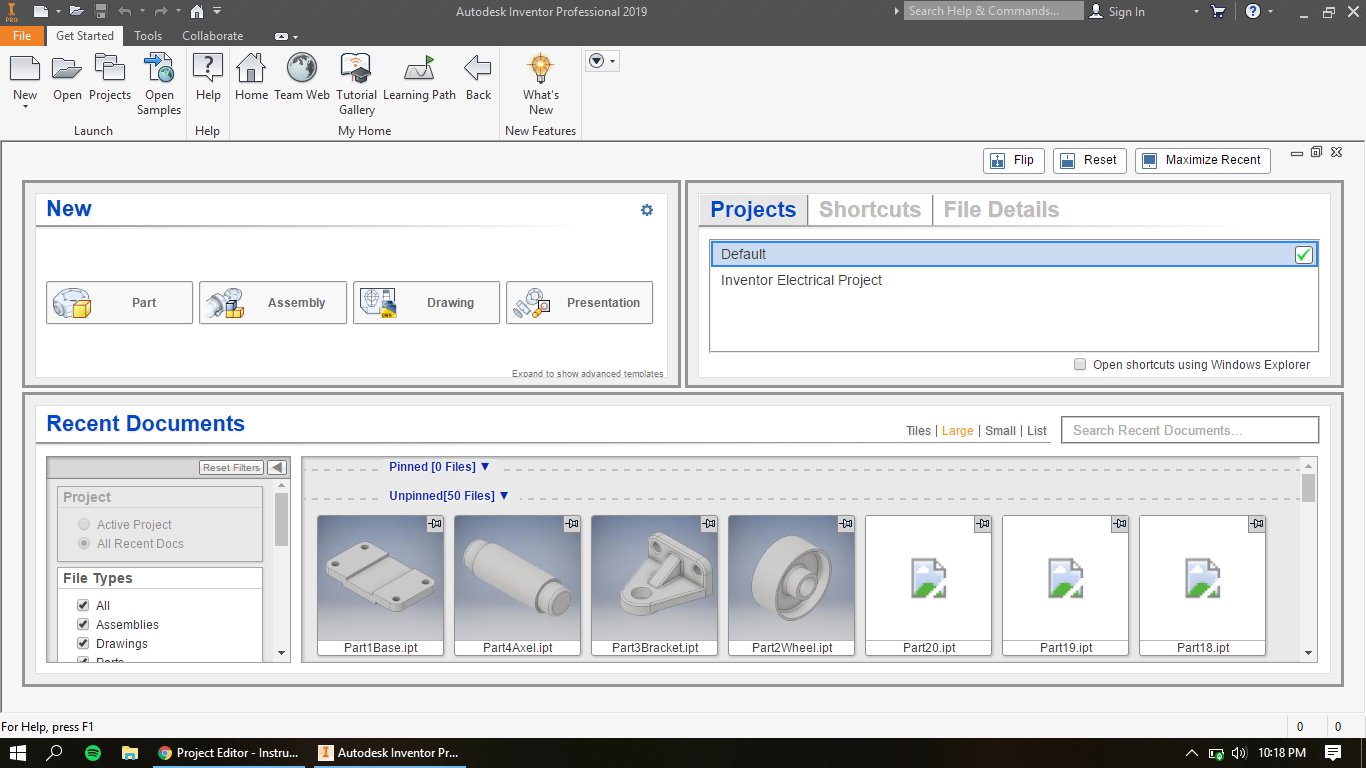
Step Two
.png)
In the "Get Started" tab, Select New.
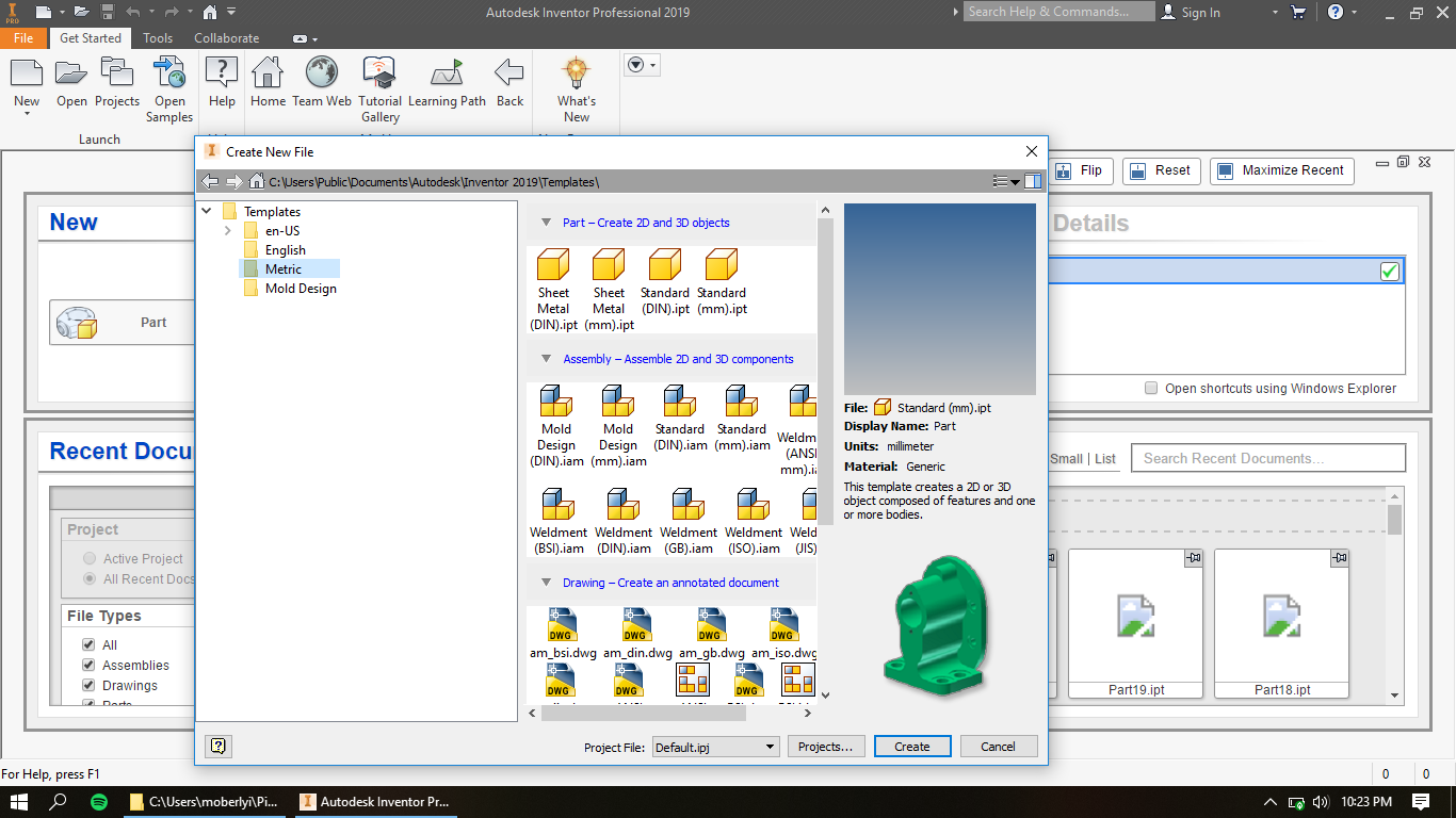
Step Three
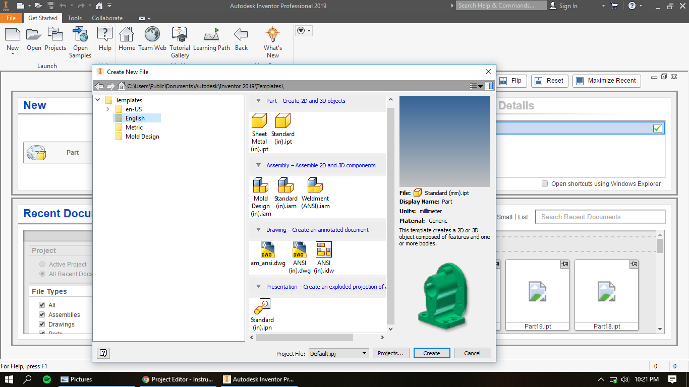.png)
Under Templates, Select English, and then under Drawing, "ANSI (in).dwg will be the drawing file to select. When selected, click Create to establish.
Step Four
.png)
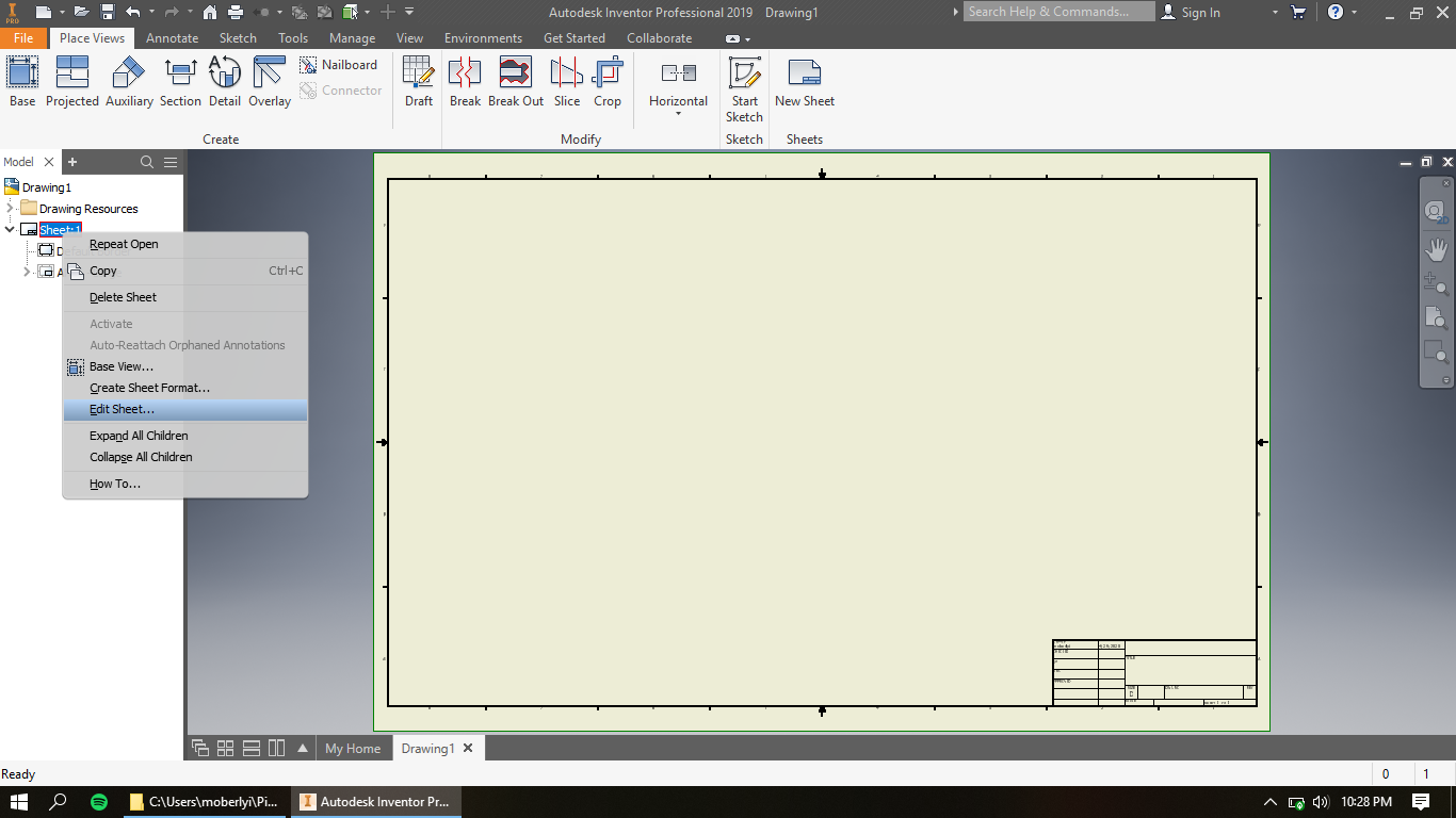
Under Drawing 1, right click on Sheet:1 to then click "Edit Sheet".
Step Five
.png)
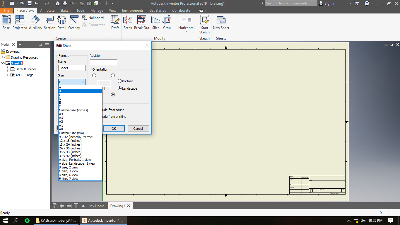
In the new window, under Size will be a drop down box where you will select size B rather than D. Select OK when done.
Step Six
.png)
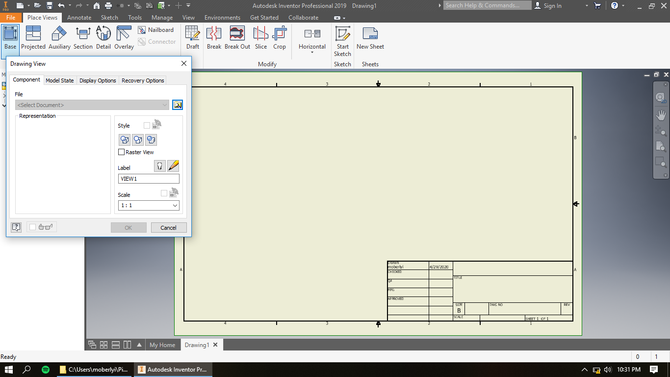
Under Place Views tab, select Base to choose the previously modeled part you wish to model.
Step Seven
.png)
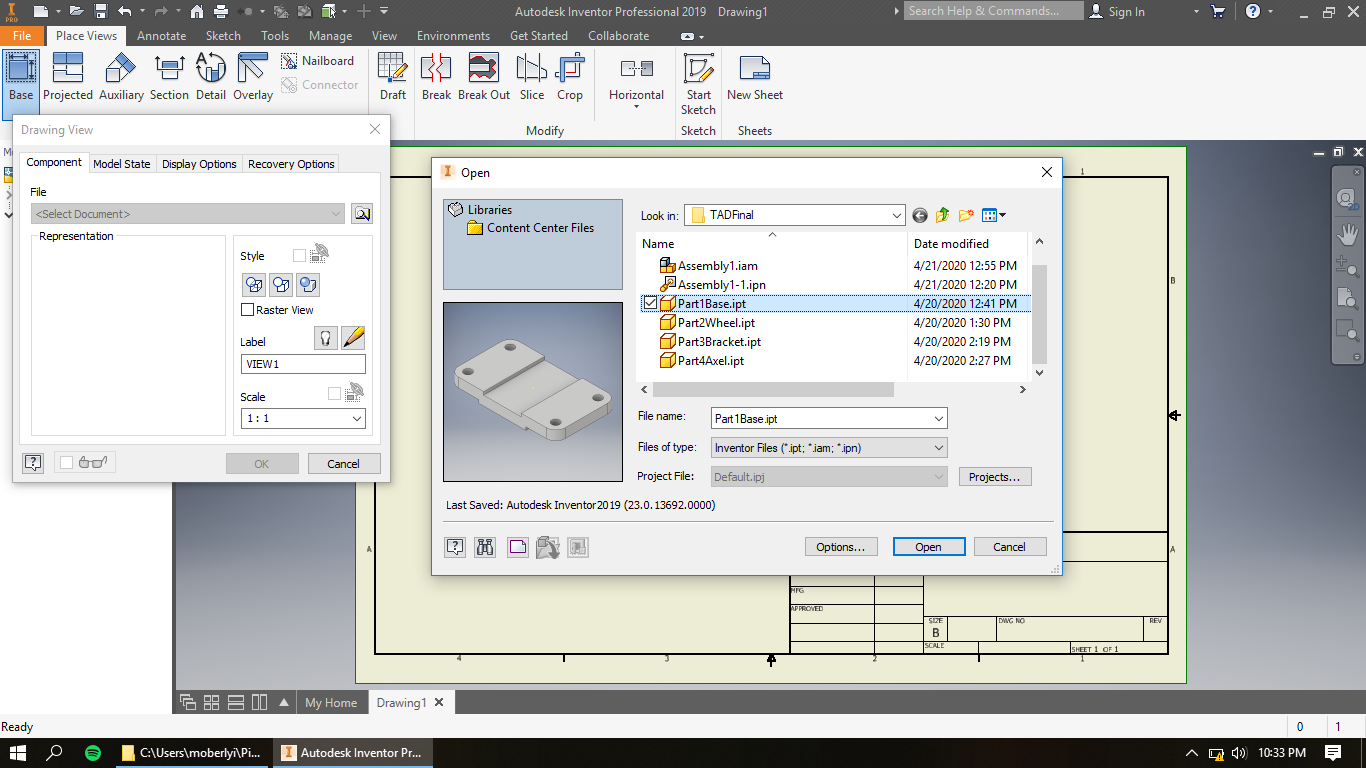
Select "open an existing file", select your desired file, and click Open.
Step Eight
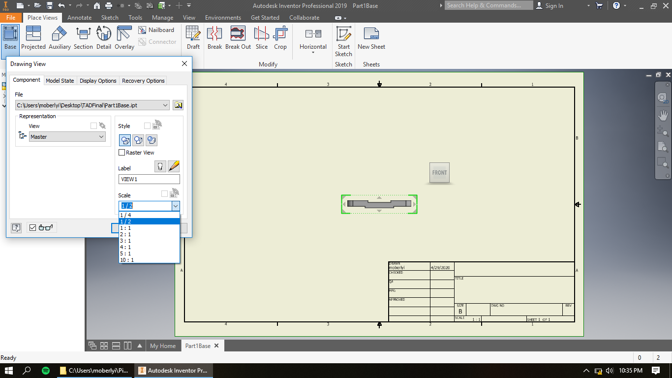.png)
Scale the part to better fit the page (while keeping in mind that you will need additional space for three additional views).
Step Nine
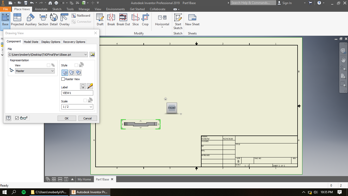.png)
Click and drag the object to its first position (being a frontal view).
Step Ten
.png)
Glide your cursor from the object over and click to establish its additional side view.
Step Eleven
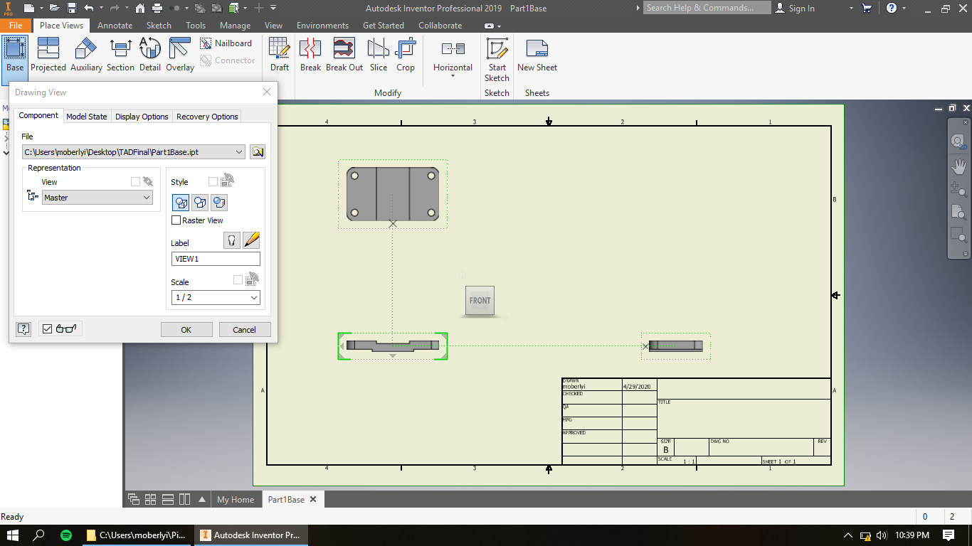.png)
Again, glide cursor from the first view up and and then click to establish that view (Top view).
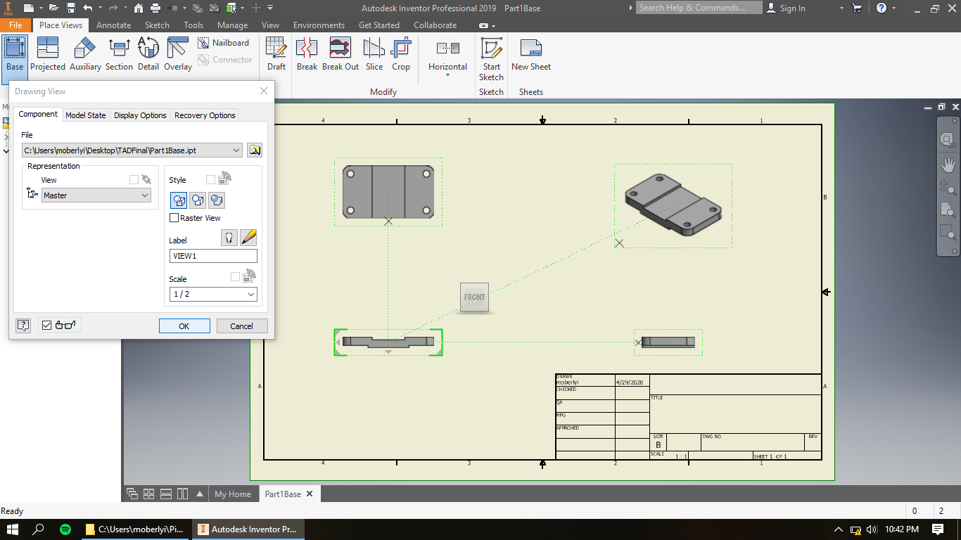
Step Twelve
.png)
For this last view (isometric view), glide your cursor between your two other views and click to finalize.
Step Thirteen
.png)
Press OK on the open window and finalize all views.
Step Fourteen
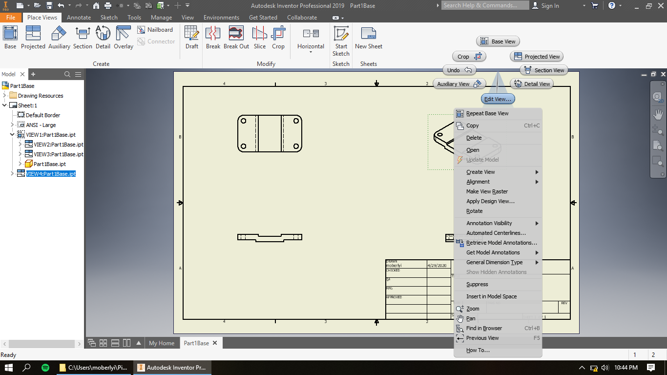.png)
Right click on the isometric view drawing view and and click edit view.
Step Fifteen
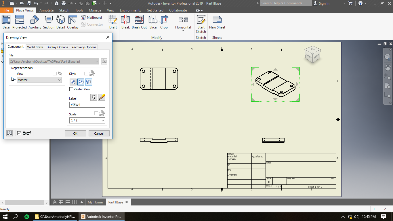.png)
Under the Style section, select the shaded button command, and then click OK.
Step Sixteen
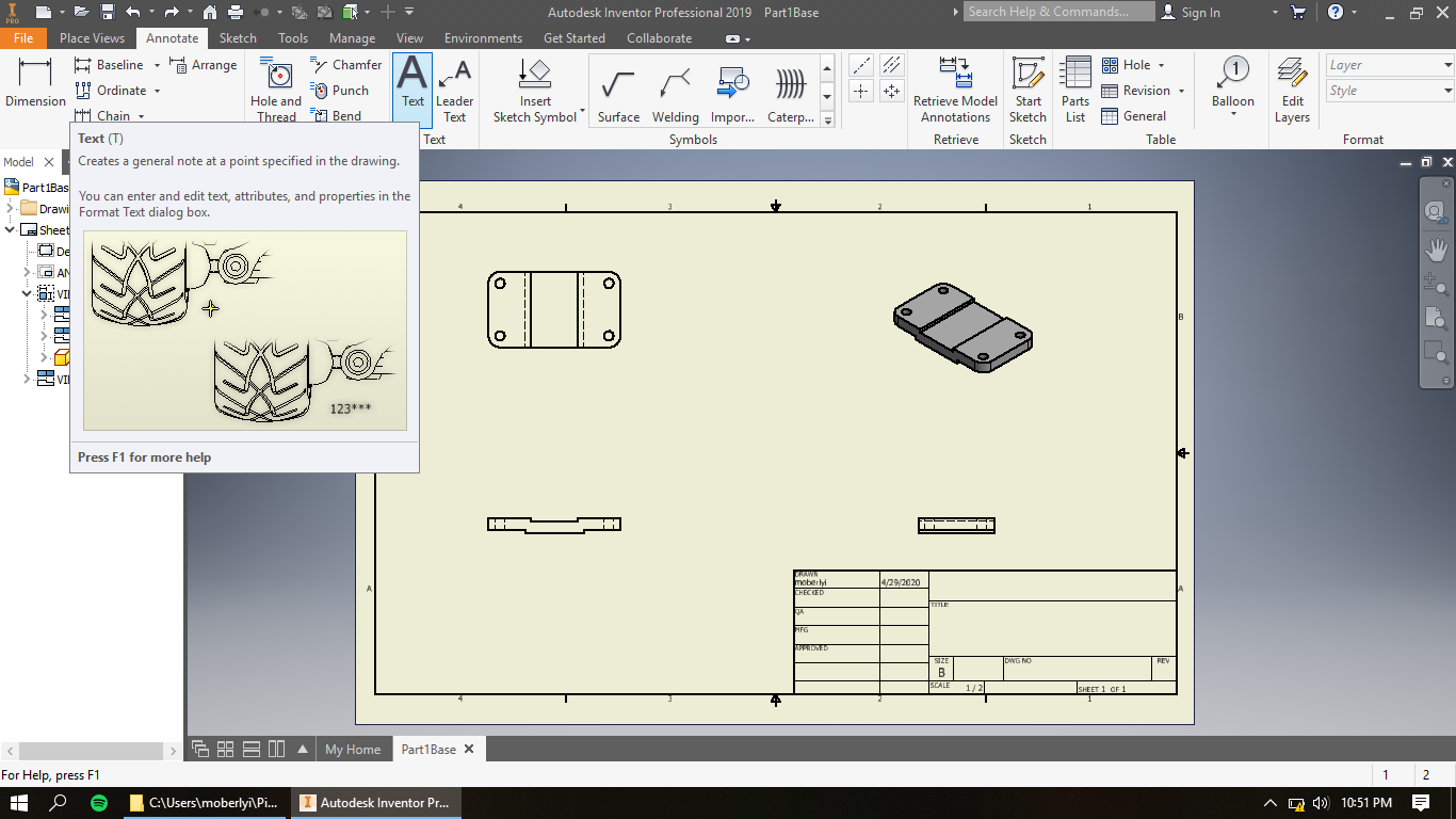.png)
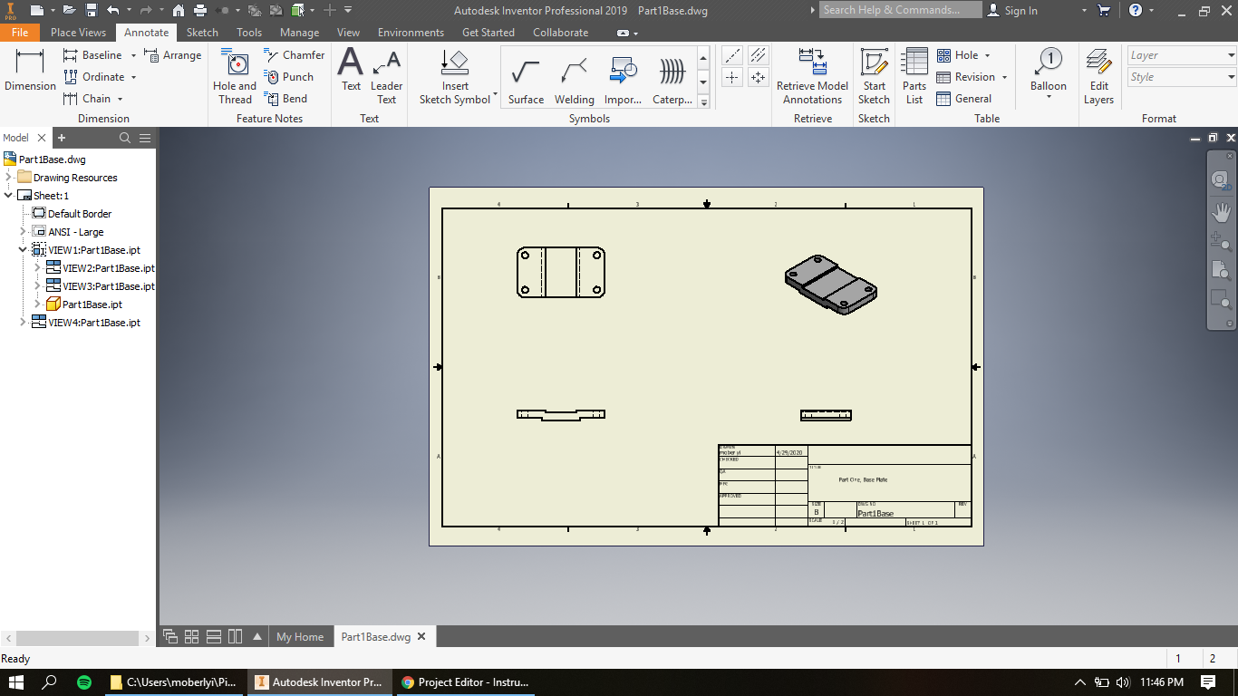
Under the Annotate tab, Select Text command.
Step Seventeen
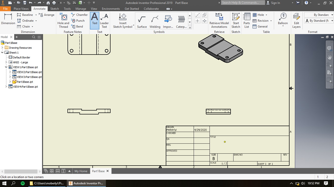.png)
Move your cursor down to the title box in the bottom right and click to prompt text box.
Step Eighteen
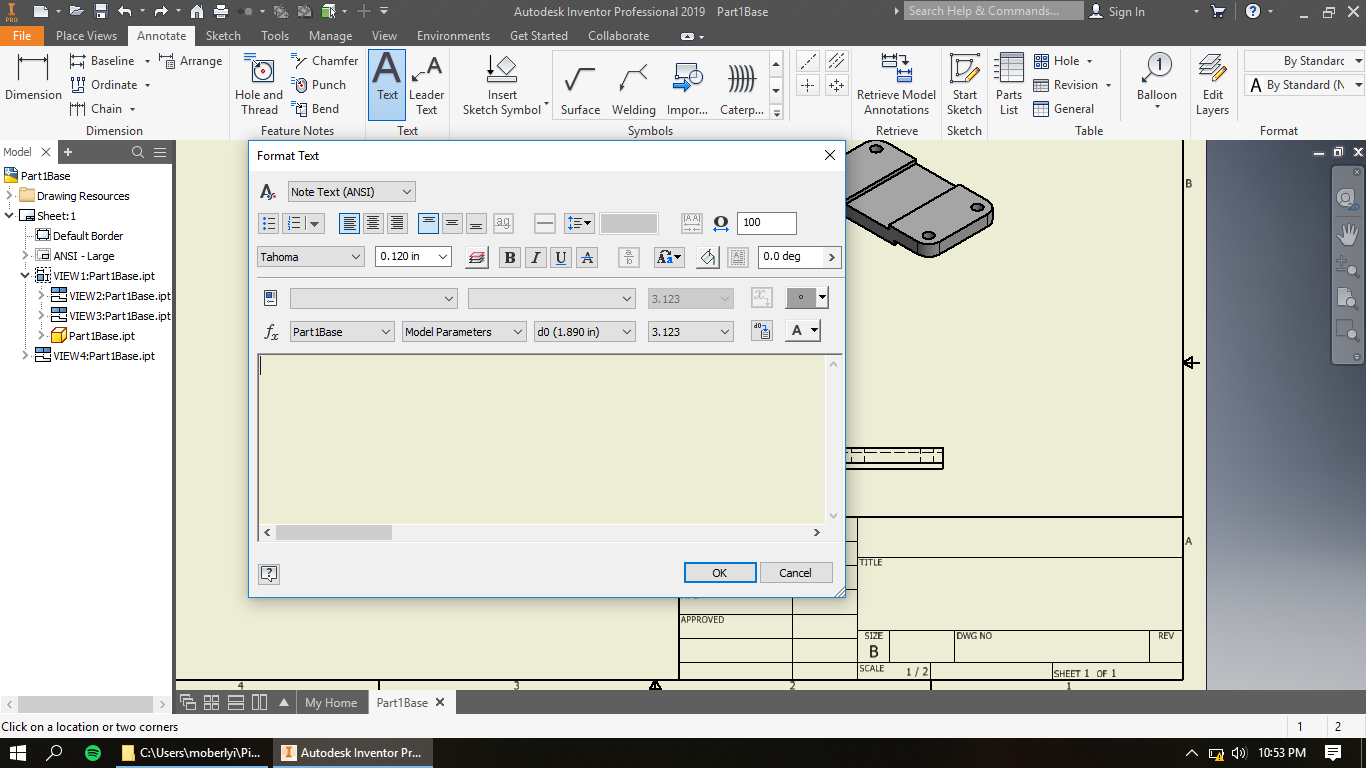.png)
Type in the title you want that pertains to the part you're modeling and then select OK.
*Keep in mind that you can also add an additional text box explaining your organization and/or your name in the box above the title box.
Step Nineteen
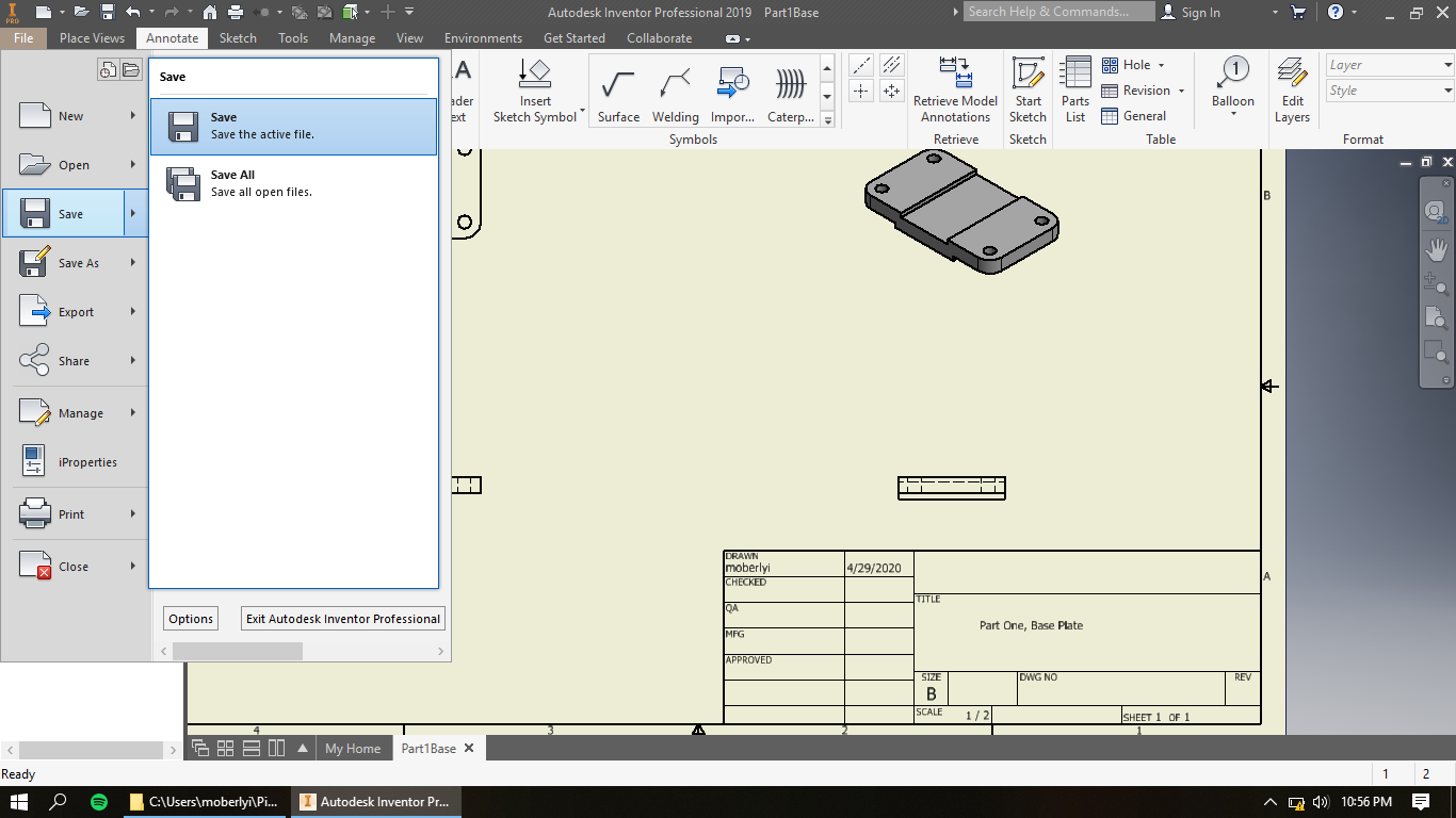.png)
Under the File tab, save the drawing to desired place.
Step Twenty
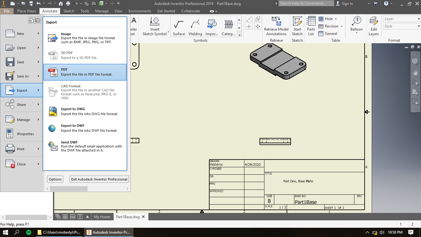.png)
For the purpose of sharing this work virtually, under the File tab, select Export, and then PDF. Select save in the promoting window do desired location.