Making a 7 Segment Display Counter With BCD Logic
by Khizer1251 in Circuits > Arduino
21567 Views, 3 Favorites, 0 Comments
Making a 7 Segment Display Counter With BCD Logic
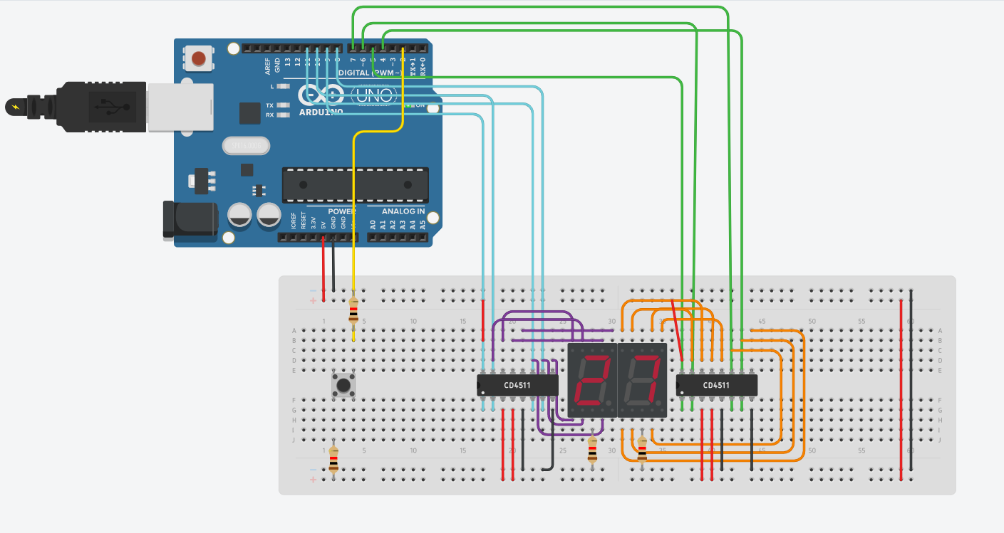
Hi everyone!
The purpose of this instructable is to guide you on making a counter/timer for your convenience, utilizing two key components; 7 segment displays and a 7 segment decoder (also known as a CD4511 chip). This project will be built and shown on the online 3D programming app, Tinkercad, to ensure the soundness of the mechanical components used. To make this, you will need to have a basic understanding of electrical circuitry, having prior knowledge of the Arduino Uno R3 and its functions, and understand basic programming logic. With that out of the way, let's get building!
Supplies
For materials, you will need to assemble the following (the materials will be available on TinkerCad):
- 1 button
- 1 Arduino Uno R3
- 2 Seven Segment Displays (Common Cathode)
- 2 1,000 ohms resistors
- Multiple jumper wires
- 2 CD4511 chip (Seven Segment Decoder)
Understanding the Components
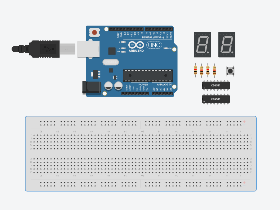
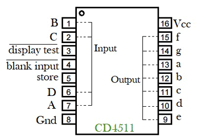
Before starting off with the physical construction of the project, I encourage you to research about the two fundamental components we will use (the CD4511 chip and the Seven Segment LED Displays) to establish a comfortable amount of theoretical knowledge.
That being said, I'll preface this paragraph with explaining the CD4511 chip. The CD4511 chip is essentially a BCD to 7-Segment decoder/driver IC, with which you can convert a binary number into a decimal number on the 7-segment display. For example, printing the number “2” on 7-segment display will require giving 0010 to the input pins (A,B,C,D) of the CD4511 chip. We can see the A, B, C, D pins on the example diagram above. We can also imprint the numbers 0-9 on a single 7-segment display. Displaying a decimal number without the usage of this chipset will require 3 more pins from the Arduino, and the circuit will become more clustered, therefore it is beneficial to use these pins.
Delving into the specifications of the other pins, pin 3 is the lamp test pin. This pin is active LOW. When HIGH, the lamp test is activated. This makes all the outputs HIGH, so if LEDs are attached to all of the outputs, all of the LEDs will turn on if this pin is HIGH. When LOW, this feature is not activated. It's simply to test all the outputs to check if they turn on. Pin 4 is the Blanking pin. This pin is active LOW. When LOW, all the outputs go LOW, so they'll all shut off, like a reset pin. When HIGH, this feature is not activated. Pin 5 is Latch Enable/STROBE and it has dual purposes depending on whether it's HIGH or LOW. When LOW, the pin is in strobe mode, meaning it strobes the output to a given device, which in this case is a 7 segment LED display. This mode is the mode we usually want it in for display purposes. So in normal operation, it's held LOW. When HIGH, it is store mode. So it simply stores latches or stores the data without transferring to a device. The other pins of the CD4511 chip will be directly connected to the 7 segment display. This concludes my explanation of the CD4511 chipset, I'll now move on to the 7 Segment LED Display.
A seven-segment display (SSD) is a widely used electronic display device for displaying decimal numbers from 0 to 9. They are most commonly used in electronic devices like digital clocks, timers and calculators to display numeric information. As its name indicates, it is made of seven different illuminating segments which are arranged in such a way that it can form the numbers from 0-9 by displaying different combinations of segments. Each of these segments can be referred to as the letters from A-G for simplification purposes. There are two types of 7 Segment LED Display's and the one we're interested in is the Common Cathode. In this, all the negative terminals (cathode) of all the 8 LEDs are connected together, named as COM. And all the positive terminals are left alone. This makes wiring significantly easier as all that you are required to do is to use one of the 1000 Ohms resistor's and connect one leg to the common terminal of each 7 Segment LED Display, and the other one on ground. This will provide functionality to all of the segments. If we were using the Common Anode version, we would need to use the resistors to power each of the segments, which is a painstaking process. The A-G pins on the display will be connected to the A-G pins of the CD4511 chip.
Placing the Components on the Breadboard
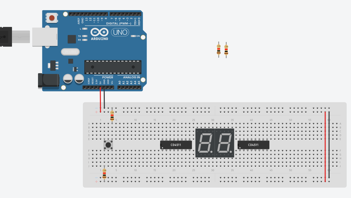
With the theory out of the way, let's begin with the physical construction of the project!
You can place the components as shown on the breadboard, or you may do it to your own convenience. What is required for you to follow is to place 2 1,000 Ohm resistors directly with each end of the button. Connect one terminal of the push button to 5V through a resistor and connect the other to the ground through resistor. The displays and the CD4511 chips can be placed anywhere within your liking, but I found that keeping them within close distance made for easier wiring. Remember to connect your power lines and ground lines correctly.
Connecting Arduino Pins to 1st CD4511 Chip
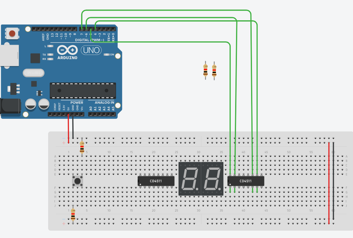
Using the diagram of the CD4511 chip shown in Step 1, we know that the BCD input pins of the chip are 1, 2, 6, and 7. TinkerCad will notify you of this when you hover over the pin, but pin 7 represents the first input, or bit 0. Likewise, pin 1 represents the second input, or bit 1. Pin 2 represents the third input, or bit 2. Pin 6 represents the fourth input, or bit 3. These pins will have to be connected to Arduino digital pins to receive input through code. Once again, you are free to use whatever pins you like, the pins I used were:
CD4511(1) -----> Arduino
- Pin 7 -----> Pin 4
- Pin 1 -----> Pin 5
- Pin 2 -----> Pin 6
- Pin 6 -----> Pin 7
Connecting the 7 Segment Display and Powering the IC
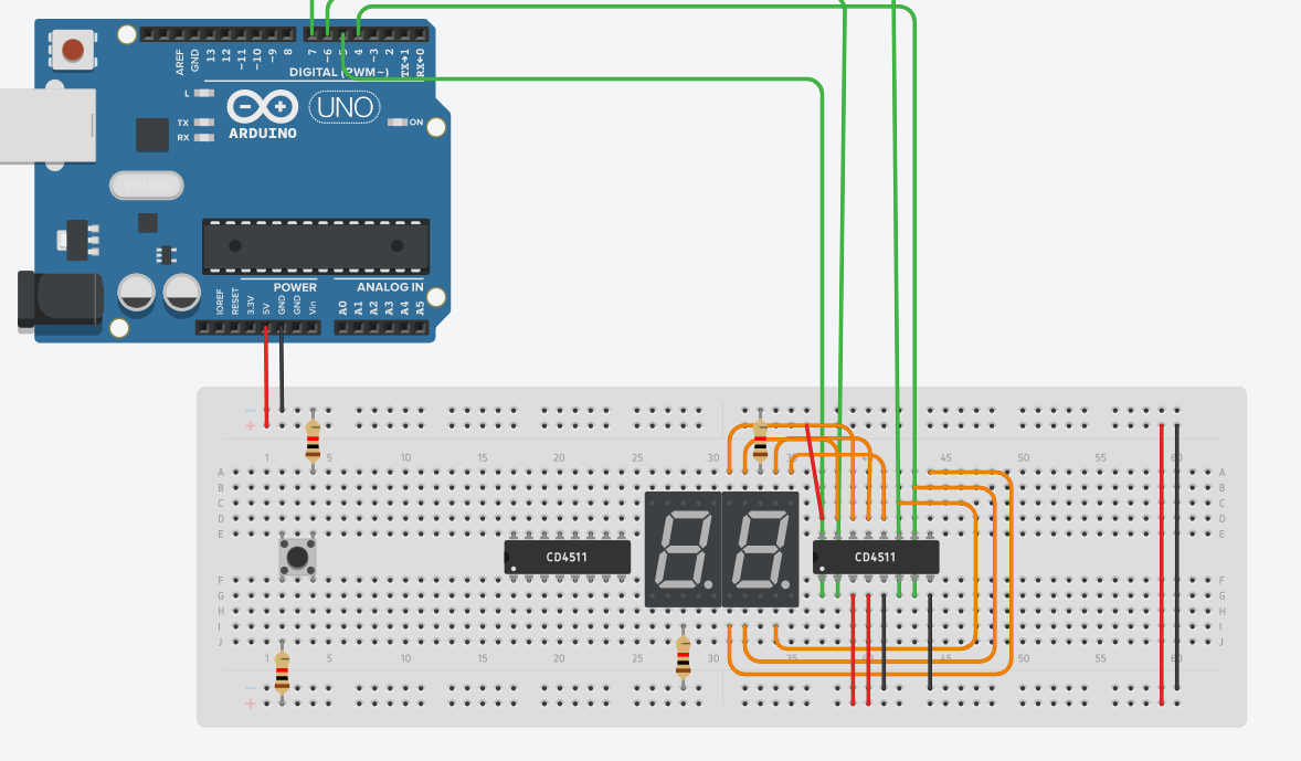
Using the diagram of the CD4511 chip shown from Step 1, notice that pins 9-15 are lettered from A-G. With this information, connect each lettered pin of the IC to its corresponding pin on the 7 segment display. For example, connect pin 9 of the IC (which is lettered E) to the E pin of the 7 segment display. This will be all the 7 segment displays to CD4511 connections.
To power the IC, provide VCC (+5V) to pins 3 and pin 4. This can be used to test whether 7 segment LED display will work as intended. If it doesn't, please check your lettered connections to make sure they are on the right pins. Provide ground to pin 5 (this is to set the pin to LOW, therefore it will strobe the output to the device rather than store it, which is beneficial to our display). Provide ground to pin 8.
Connecting the Other CD4511 IC With 2nd Display
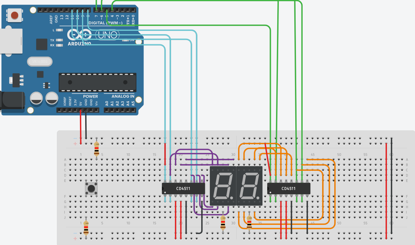
Following the same logic in step 3, the following connections can be made:
CD4511(2) -----> Arduino
- Pin 7 -----> Pin 8
- Pin 1 -----> Pin 9
- Pin 2 -----> Pin 10
- Pin 6 -----> Pin 11
Connect the lettered pins of the IC to the 7 segment display, and make the same power and ground connections as shown in Step 4.
Creating a Sketch to Represent a Counter and Running It
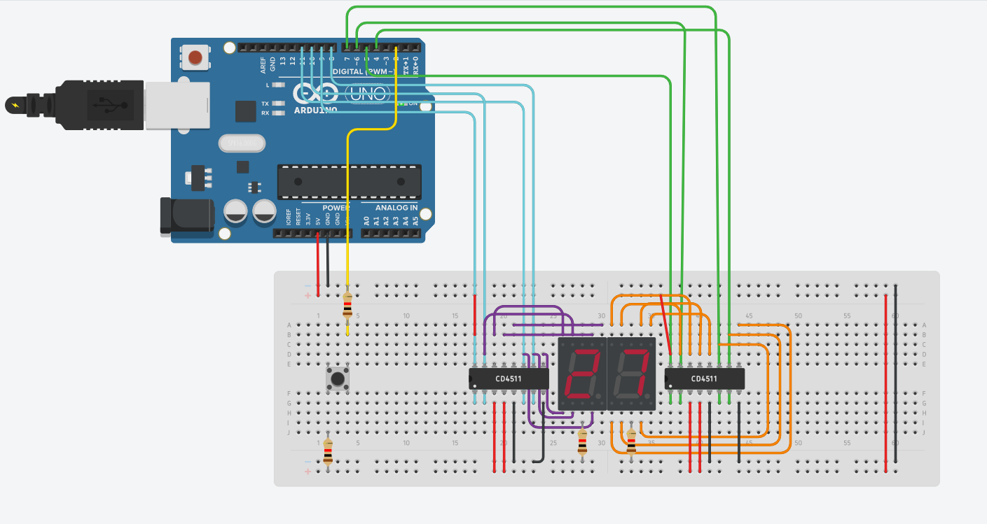
//BCD 1, these are the digital pins of the first CD4511 chip, the one placed on the right hand

side of the picture. They will be used to output bits to the input pins of the IC.

int a1 = 4;
int a2 = 5;
int a3 = 6;
int a4 = 7;

//BCD 2, same as above but different pins
int b1 = 8;
int b2 = 9;
int b3 = 10;
int b4 = 11;

int n=0; //Setting initial value of n to 0, n serves as a placeholder value of our button

which will trigger the countdown
int d1;
int d2;
int button = 2;
int state = 0;

void setup() //this will set all the pins to output, and the button pin (2) to input to receive

an electrical signal.
{
  pinMode(4,OUTPUT);
  pinMode(5,OUTPUT);
  pinMode(6,OUTPUT);
  pinMode(7,OUTPUT);
  pinMode(8,OUTPUT);
  pinMode(9,OUTPUT);
  pinMode(10,OUTPUT);
  pinMode(11,OUTPUT);
  pinMode(button,INPUT);
}

void loop(){
 state = digitalRead(button); //as long as the button is pressed
 if(state == HIGH)
   n++; //increase n's value

 if(n==100)
   n=0;

 d1=n%10; // This will divide n by 10 and the remainder will be stored in d1, this will hold the placeholder value for the first 7 segment display
 d2=n/10; // This will divide n by 10 and the value before decimal will be stored in d2, this will hold the placeholder value for the second 7 segment display
 disp1(d1);
 disp2(d2);
 delay(100);//100 ms delay to debounce
}

void disp1(int num){ //this method entails making 0-9 combinations using the BCD pins by sending different outputs to turn each segment on or off.
  if(num == 0)//0000
  {
    digitalWrite(a1, LOW);
    digitalWrite(a2, LOW);
    digitalWrite(a3, LOW);
    digitalWrite(a4, LOW);
  }
  if(num == 1)//0001
  {
    digitalWrite(a1, HIGH);
    digitalWrite(a2, LOW);
    digitalWrite(a3, LOW);
    digitalWrite(a4, LOW);
  }
  if(num == 2)//0010
  {
    digitalWrite(a1, LOW);//0
    digitalWrite(a2, HIGH);//1
    digitalWrite(a3, LOW);//0
    digitalWrite(a4, LOW);//0
  }
  if(num == 3)//0011
  {
    digitalWrite(a1, HIGH);//1
    digitalWrite(a2, HIGH);//1
    digitalWrite(a3, LOW);//0
    digitalWrite(a4, LOW);//0
  }
  if(num == 4)//0100
  {
    digitalWrite(a1, LOW);//0
    digitalWrite(a2, LOW);//0
    digitalWrite(a3, HIGH);//1
    digitalWrite(a4, LOW);//0
  }
  if(num == 5)//0101
  {
    digitalWrite(a1, HIGH);//1
    digitalWrite(a2, LOW);//0
    digitalWrite(a3, HIGH);//1
    digitalWrite(a4, LOW);//0
  }
  if(num == 6)//0110
  {
    digitalWrite(a1, LOW);//0
    digitalWrite(a2, HIGH);//1
    digitalWrite(a3, HIGH);//1
    digitalWrite(a4, LOW);//0
  }
  if(num == 7) //0111
  {
    digitalWrite(a1, HIGH);//1
    digitalWrite(a2, HIGH);//1
    digitalWrite(a3, HIGH);//1
    digitalWrite(a4, LOW);//0
  }
  if(num == 8) //1000
  {
    digitalWrite(a1, LOW);//0
    digitalWrite(a2, LOW);//0
    digitalWrite(a3, LOW);//0
    digitalWrite(a4, HIGH);//1
  }
  if(num == 9)//1001
  {
    digitalWrite(a1, HIGH);//1
    digitalWrite(a2, LOW);//0
    digitalWrite(a3, LOW);//0
    digitalWrite(a4, HIGH);//1
  }
}

void disp2(int num) //same as above
{
  if(num == 0)//0000
  {
    digitalWrite(b1, LOW);//
    digitalWrite(b2, LOW);//0
    digitalWrite(b3, LOW);//0
    digitalWrite(b4, LOW);//0
  }
  if(num == 1)//0001
  {
    digitalWrite(b1, HIGH);//1
    digitalWrite(b2, LOW);//0
    digitalWrite(b3, LOW);//0
    digitalWrite(b4, LOW);//0
  }
  if(num == 2)//0010
  {
    digitalWrite(b1, LOW);//0
    digitalWrite(b2, HIGH);//1
    digitalWrite(b3, LOW);//0
    digitalWrite(b4, LOW);//0
  }
  if(num == 3)//0011
  {
    digitalWrite(b1, HIGH);//1
    digitalWrite(b2, HIGH);//1
    digitalWrite(b3, LOW);//0
    digitalWrite(b4, LOW);//0
  }
  if(num == 4)//0100
  {
    digitalWrite(b1, LOW);//0
    digitalWrite(b2, LOW);//0
    digitalWrite(b3, HIGH);//1
    digitalWrite(b4, LOW);//0
  }
  if(num == 5) //0101
  {
    digitalWrite(b1, HIGH);//1
    digitalWrite(b2, LOW);//0
    digitalWrite(b3, HIGH);//1
    digitalWrite(b4, LOW);//0
  }
  if(num == 6) //0110
  {
    digitalWrite(b1, LOW);//0
    digitalWrite(b2, HIGH);//1
    digitalWrite(b3, HIGH);//1
    digitalWrite(b4, LOW);//0
  }
  if(num == 7) //0111
  {
    digitalWrite(b1, HIGH);//1
    digitalWrite(b2, HIGH);//1
    digitalWrite(b3, HIGH);//1
    digitalWrite(b4, LOW);//0
  }
  if(num == 8) //1000
  {
    digitalWrite(b1, LOW);//0
    digitalWrite(b2, LOW);//0
    digitalWrite(b3, LOW);//0
    digitalWrite(b4, HIGH);//1
  }
  if(num == 9)//1001
  {
    digitalWrite(b1, HIGH);//1
    digitalWrite(b2, LOW);//0
    digitalWrite(b3, LOW);//0
    digitalWrite(b4, HIGH);//1
  }
}
//this is not meant to be copy pasted, I have included a downloadable version of the code if you wish to try it.
Downloads
Enjoy
If all the steps/logic was executed correctly, your project should execute perfectly. With the press of a button, the timer continues to go from 0 - 99 and resets. If you hold off the button, it stops! Thank you for taking the time to read this instructible