Making a 3D Printer Data of Case for Electronic Module by Blender.
by saharaupro in Circuits > Electronics
229 Views, 2 Favorites, 0 Comments
Making a 3D Printer Data of Case for Electronic Module by Blender.
You need them(Example I used).
3D Printer(TEVO Tarantula)
2D Scanner(CanoScan LiDE 200)
3D Data Editor(Blender)
2D Data Editor(Paint Shop Pro)
Scan Your Electronic Modules.
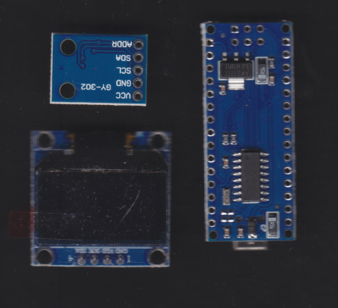
Scan your electronic modules by 2D scanner.
Remember dot per pixel value (dpi) of scanning.
In my case it was 600dpi.
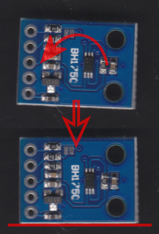
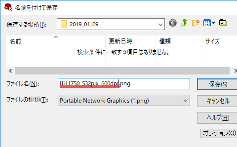
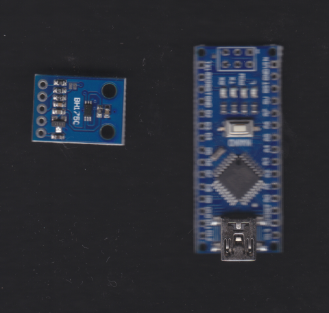
Rotate, trimming and save every image of modules.
Remember the number of pixels of images.
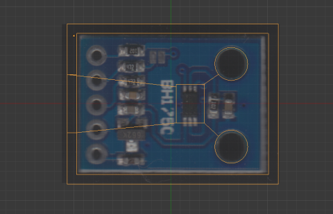
In the case of this module, it was 532 pixels.
I named this image as BH1750_532pix_600dpi.
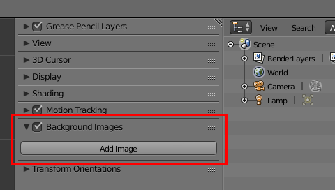
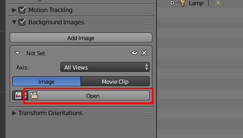
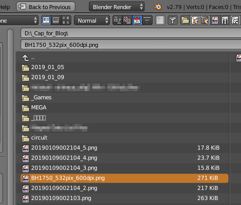
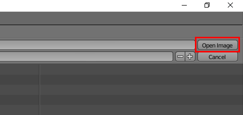
Read background image in Blender.
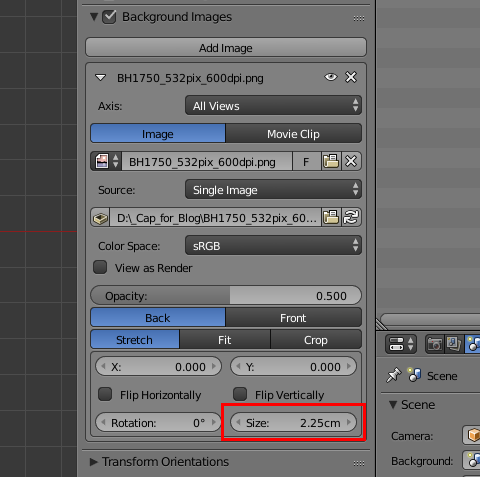
Calculate and set the image size.
It is 532 / 600 *2.54 = 2.25cm in here.
[pixel number] divided by [dpi value of scanning (pixel per inch)] times [2.54 (cm/inch)]
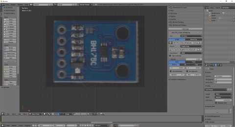

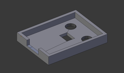
And then you can fit the 3D objects to the image of the module in Blender.