Making a 3-D Printed Mold
by rachel in Workshop > 3D Printing
114419 Views, 164 Favorites, 0 Comments
Making a 3-D Printed Mold
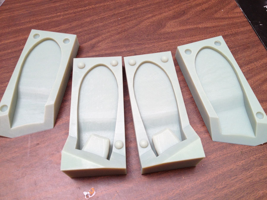
I recently had a project where I needed to create a couple dozen identical foam ear shapes. Casting from a mold is the clear solution here. However, the ears needed to fit onto an existing product, so I knew some tweaking of the design would be necessary to get it right before I could make the dozens. I was able to use Instructables' Objet Connex printers to make my molds, based on CAD drawings I made, and after a couple tweaks I got the design right and was able to make the full run.
In this Instructable I'll share what I learned about how to draw a CAD for a mold and 3D printing it out. I will assume you have access to and moderate proficiency with a CAD system (it doesn't matter what kind). For the printing, if you want to make your own but don't have access to a 3D printer, there are many services which print for a fee, or Instructables may be able to do that for you. The actual casting I will leave out as I was using an expanding polyurethane foam, which is not a generally applicable material.
Unfortunately my print picture set and my mold CAD picture set do not show the same mold. The pictures of the print, in the second half of the instructable, are of a slightly more complex mold, with a two-plane parting line. The process I outline is the same for both, however.
CAD Prep
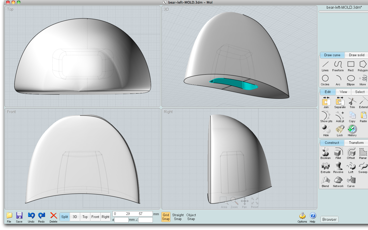
For the purposes of this instructable, which is about 3-d printing a mold, I am going to assume you have an original object already drawn, or can obtain one from (for example) Thingiverse or another source.
First, ensure you have a "solid" object, rather than abutting surfaces. The object must be theoretically water-tight. Save it as a new file (I just call mine 'originalname-MOLD.3dm'). Next, consider the orientation of the mold. It doesn't have to be printed such that the object is in its expected upright position, it can be at any angle that is suitable for casting. Do you have a flat bottom, such that you can make a one-piece mold, or do you need a parting line, the join where the mold will come apart to extract the casting? If so, where is the best place for it? In general this should be at the widest part of the object, and it is often easier to extract the casting if the parting line runs more or less along the length, rather than width or height, of the object. If you have undercuts in the object, significant concave areas, consider placing the parting line through or near these. Good parting line placement is a bit of an art.
If the parting line has to be highly shaped, the technique becomes more difficult; for this simple tutorial I am assuming a straight parting line, either in one plane or only on a few intersecting planes. If you are planning cast with a flexible material such as silicone or foam, you can get away with fudging some of these guidelines a small amount as I did in the example.
Mold Box and Parting Line
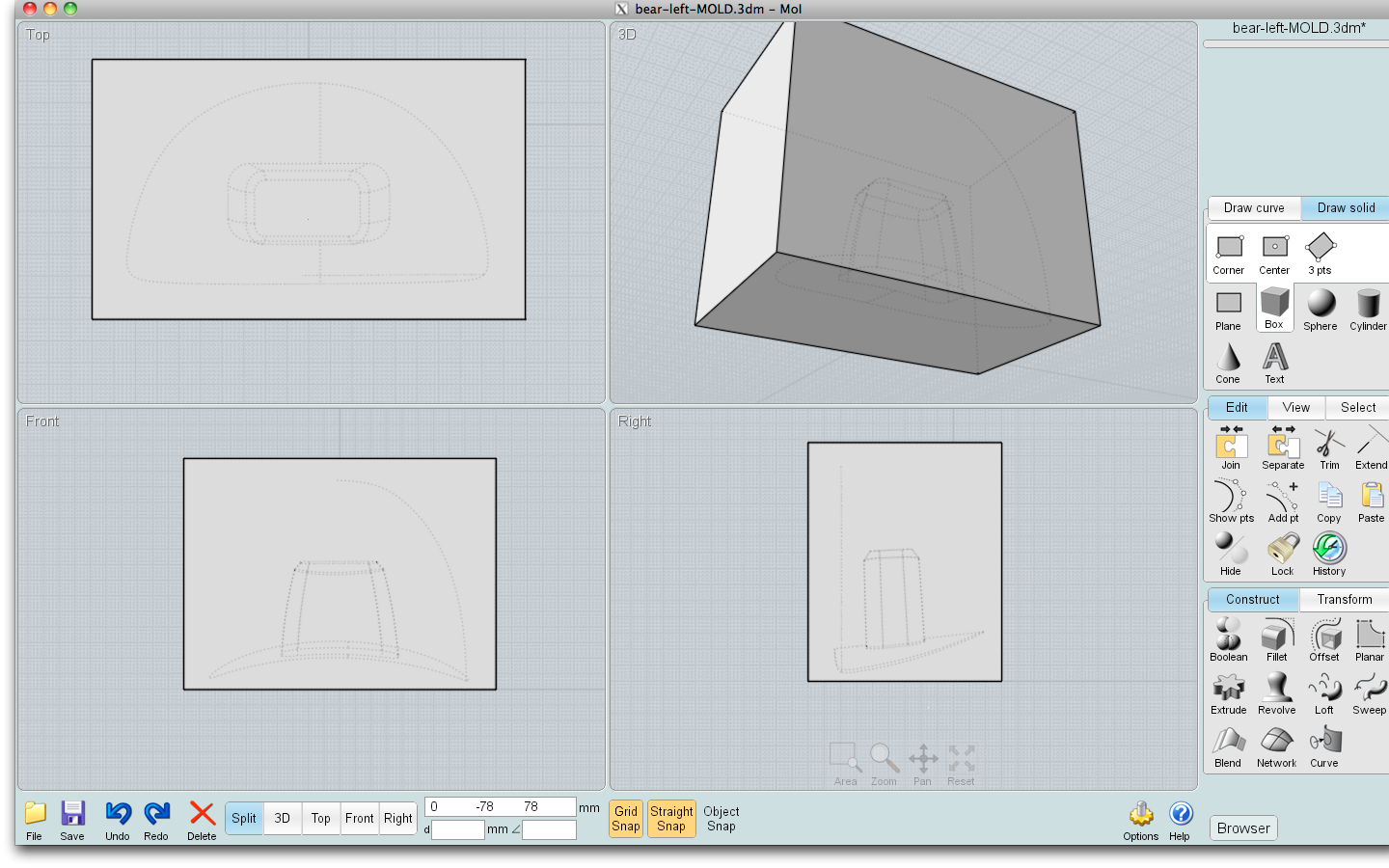
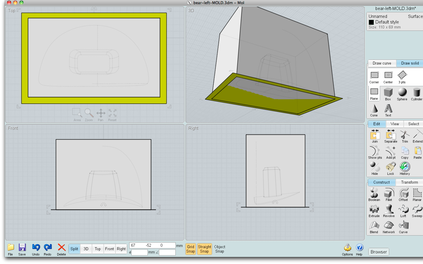
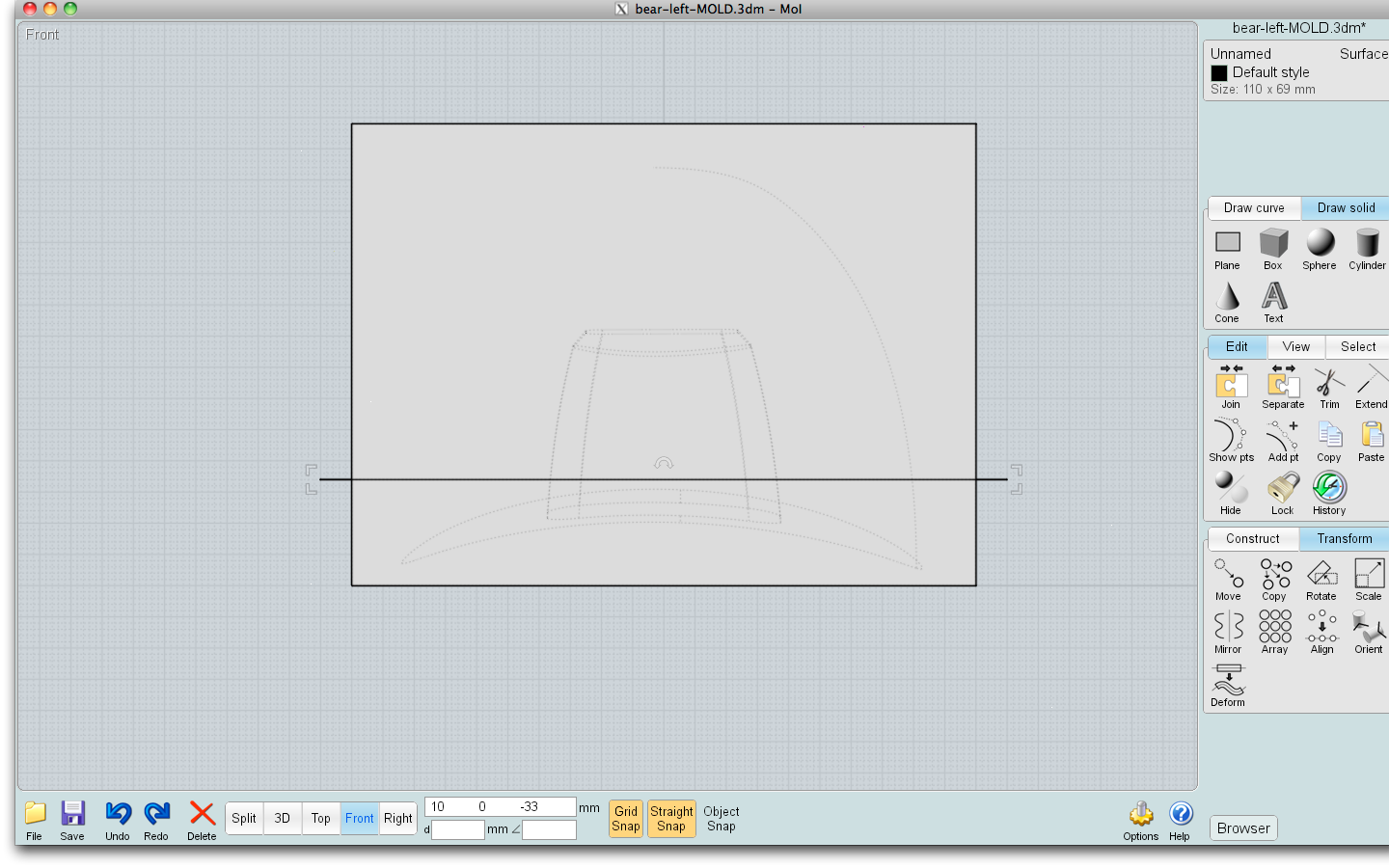
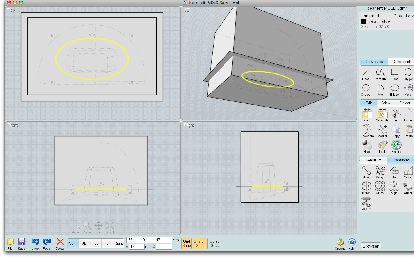
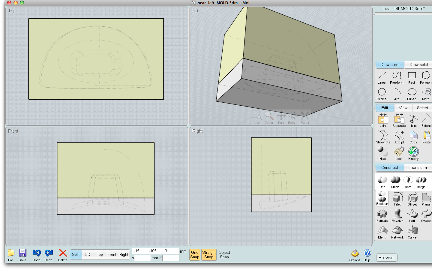
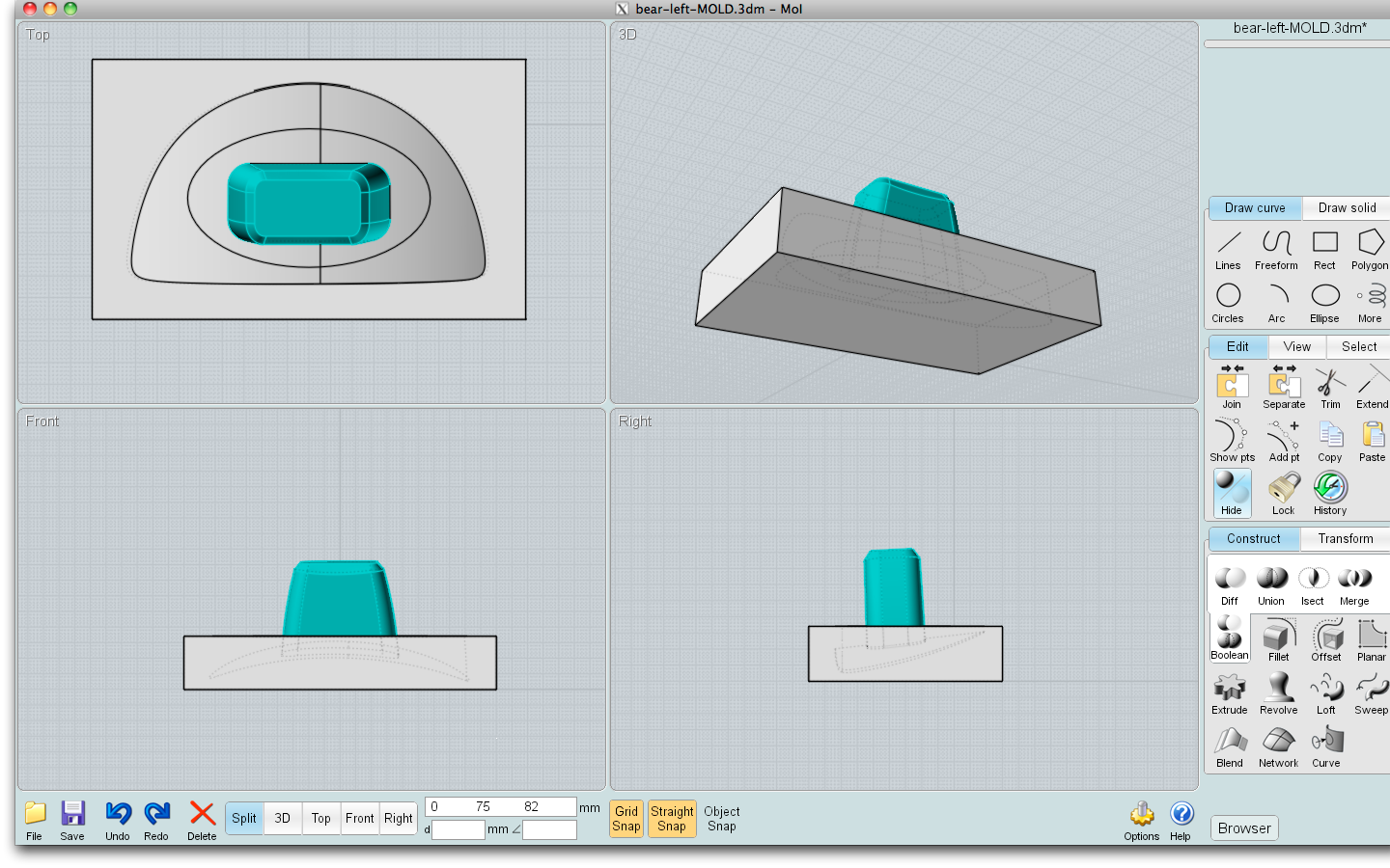
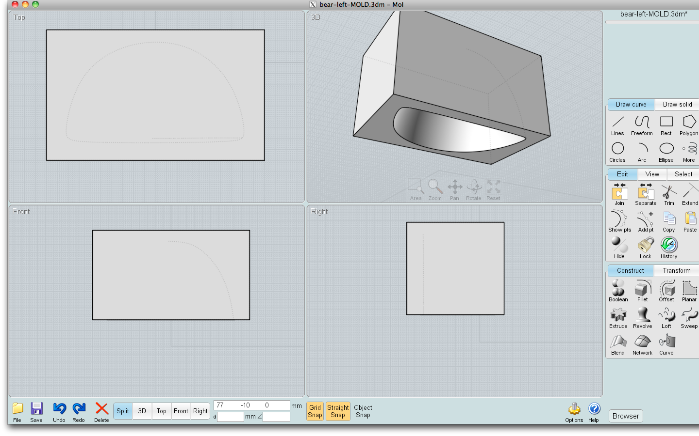
Arrange your original object square to how you decided the mold should be printed. Draw a 3D box around your original, leaving at least a centimeter or so around all sides. You can cut it down later to save on material (a good idea if you are using a service that charges by volume).
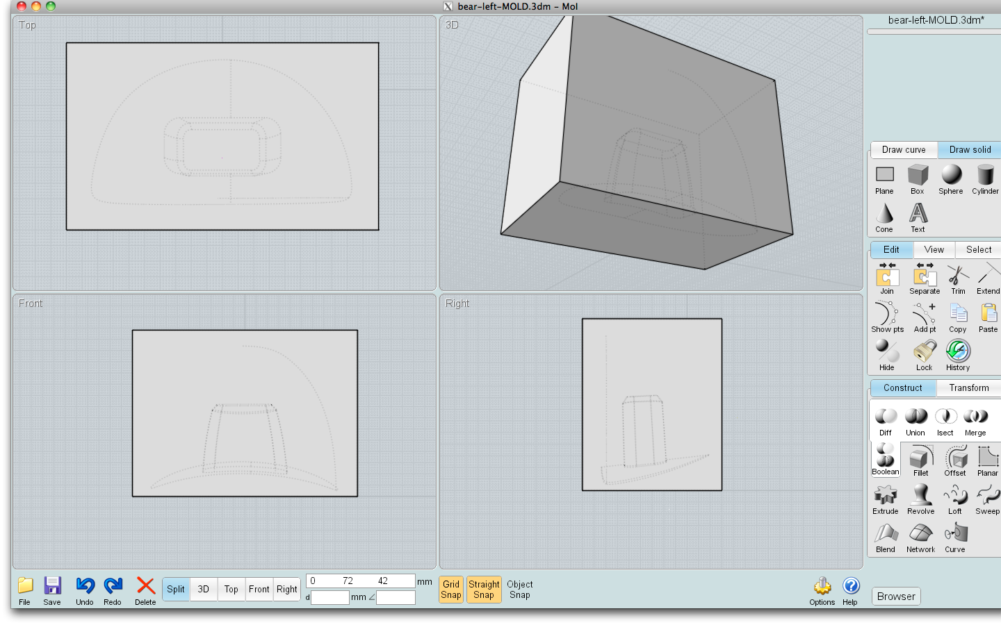
With the box selected, 'diff' or 'subtract' your original (you may need to hide the box to select the original depending on how your CAD app works).
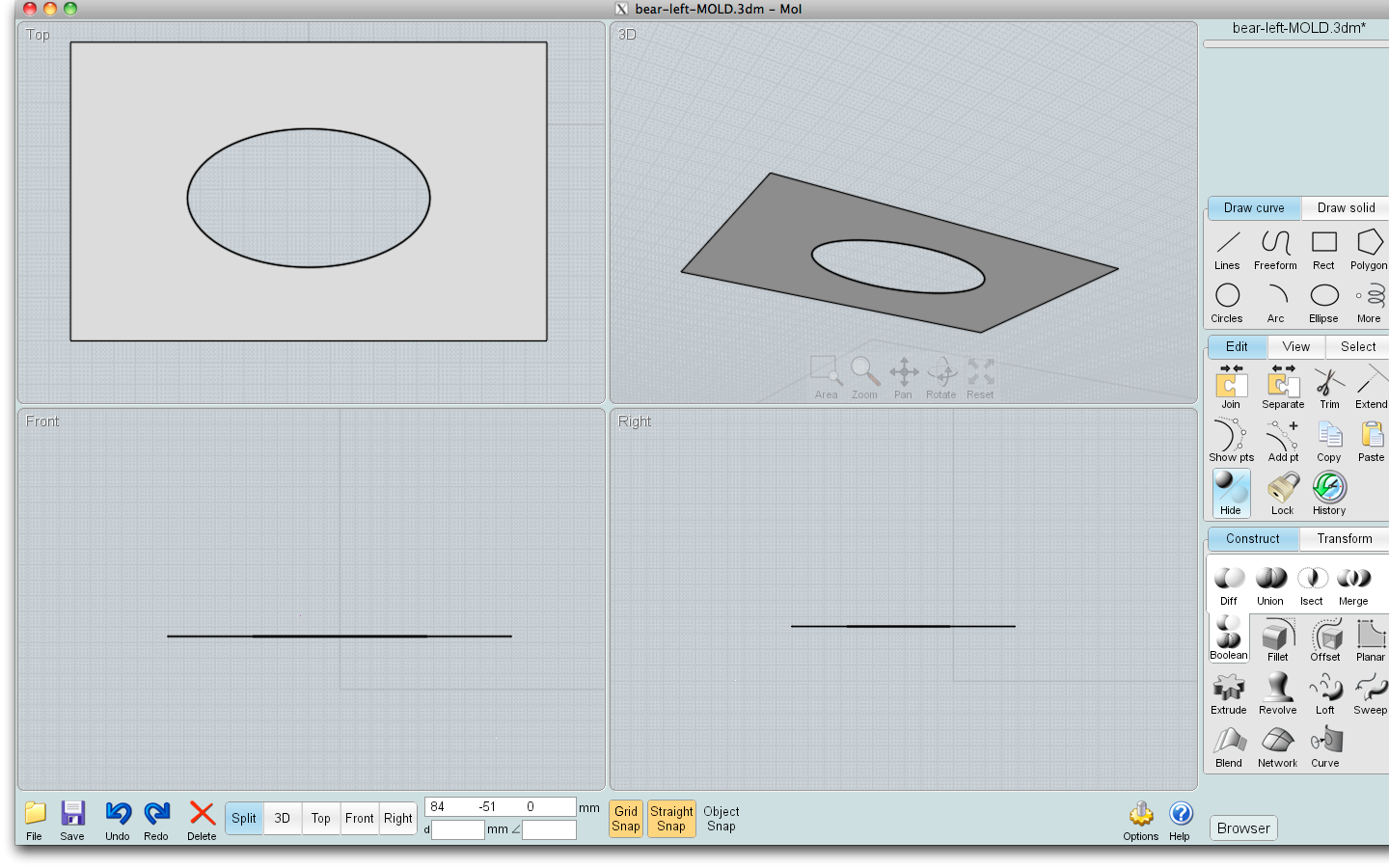
Now create the parting line. Make a plane, or several, at the widest point(s) of your object. Each plane must be bigger than the box, at the area where it comprises the parting line, or it won't "cut" properly. You may have a section of the original that needs to pass through the parting line plane without being cut by it (see the pics). Simply make a hole in the plane around it.
Now use your intersection tool, or cut or subtract or diff or whatever it is called, to break up the box by the plane(s). If you got a complete cut (don't worry if you have more than two pieces, you can rejoin them later), delete the planes.
Registration Keys and Trimming
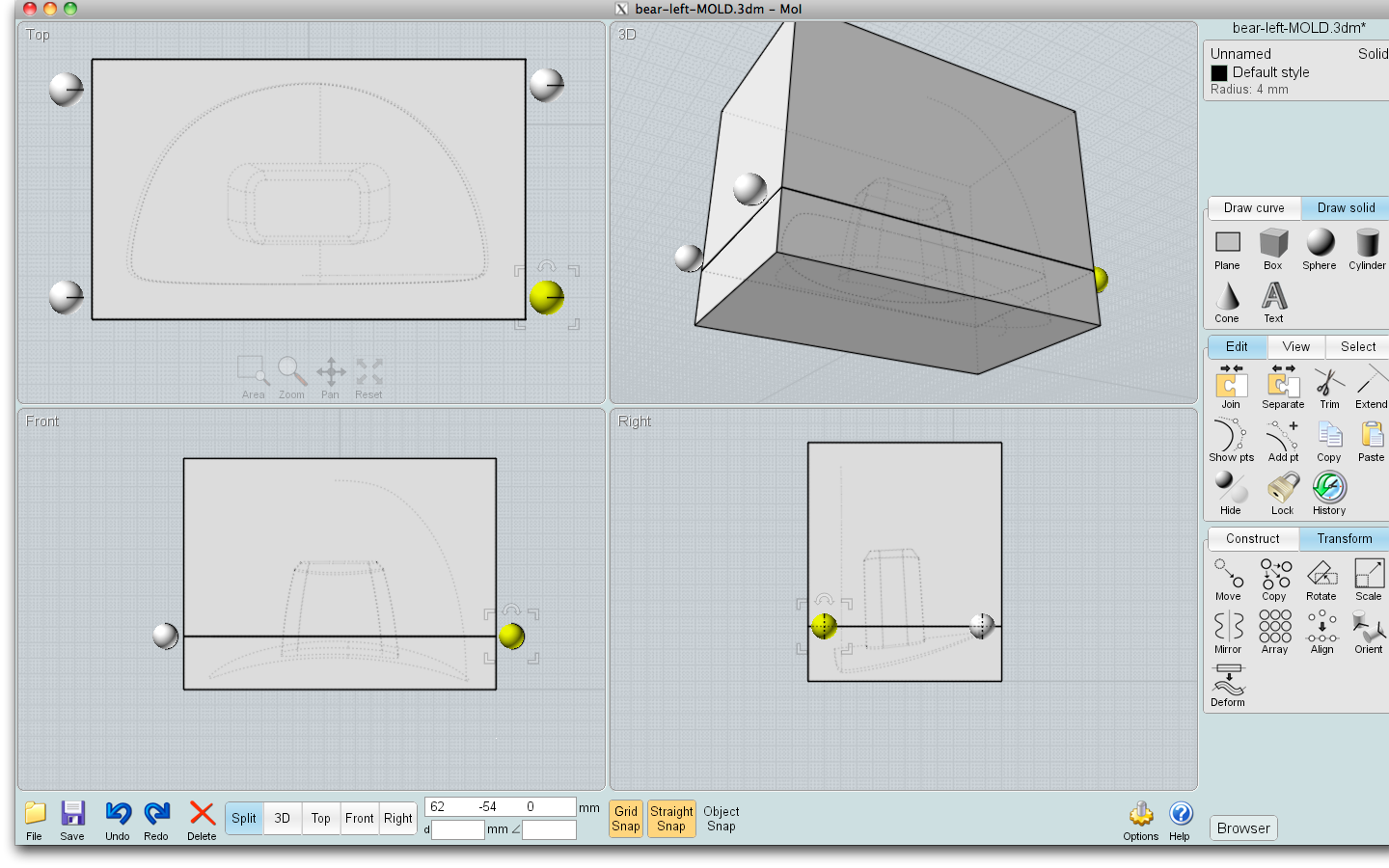
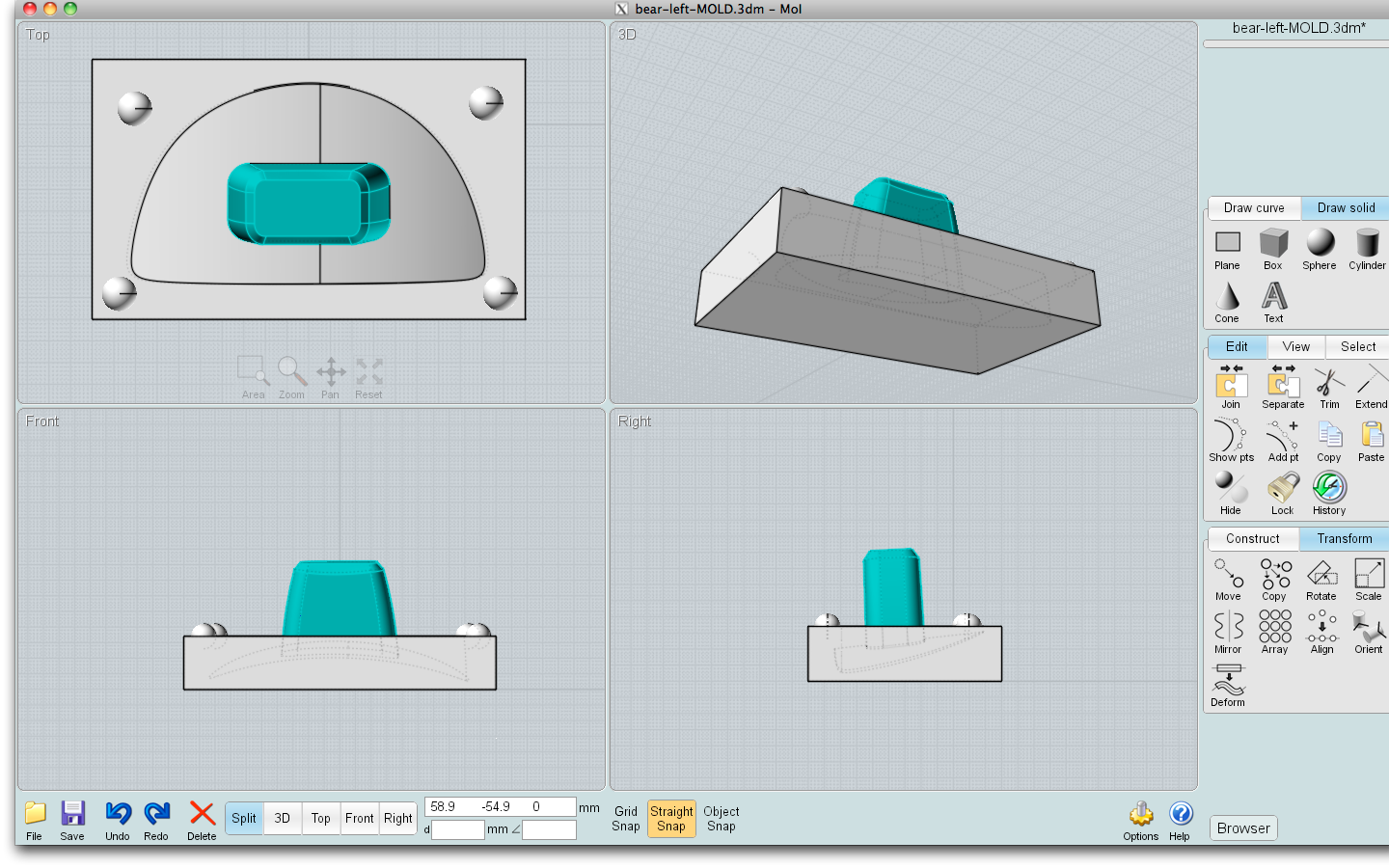
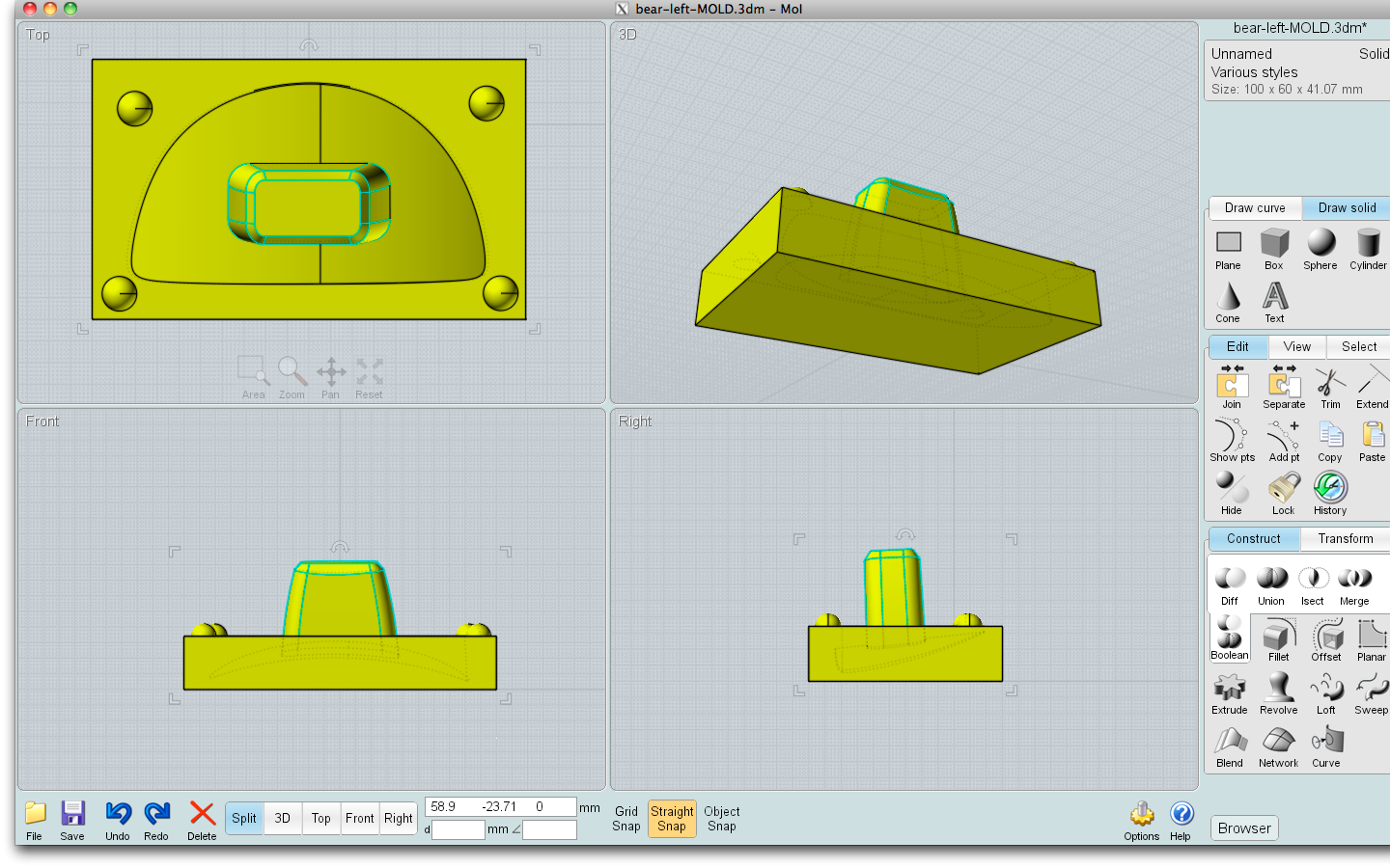
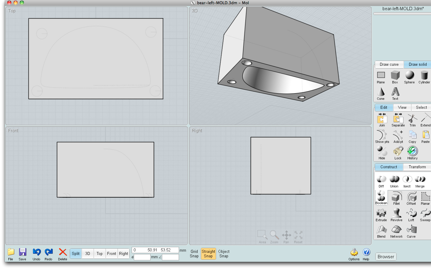
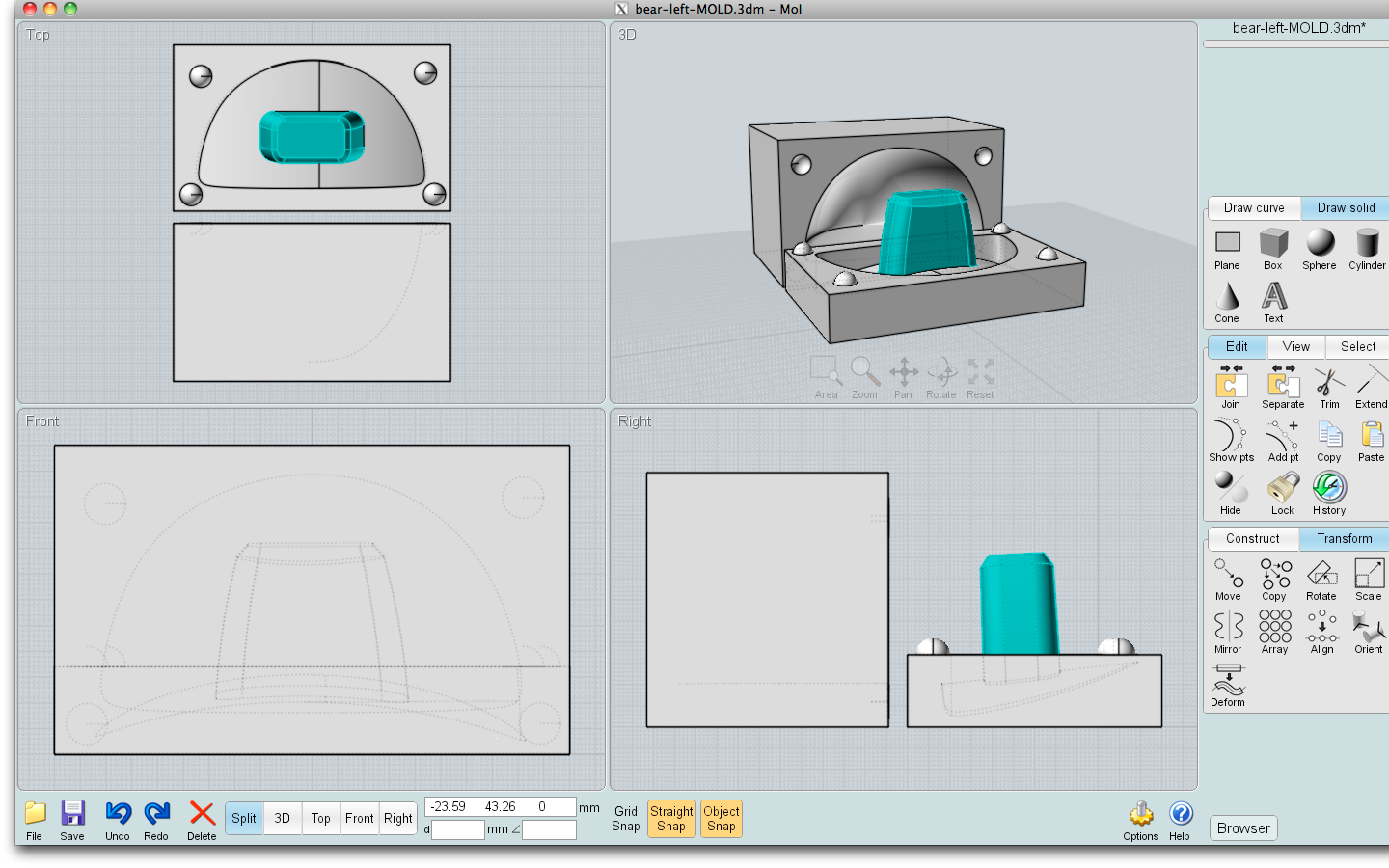
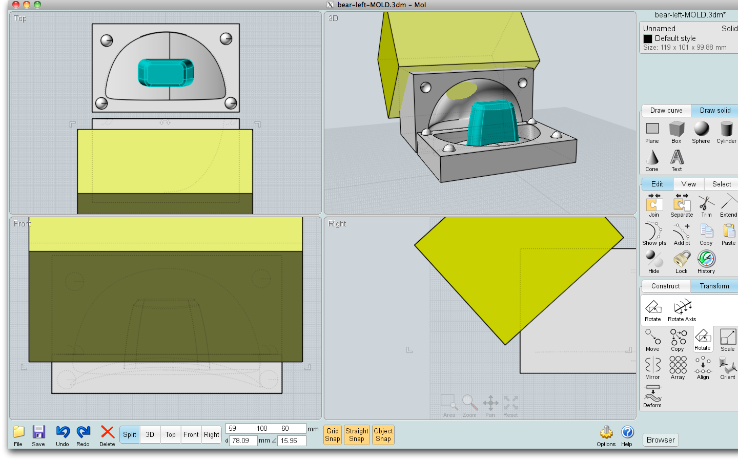
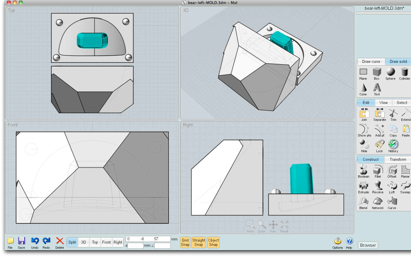
In order for the mold halves to stay together without shifting, create registration keys. Draw at least two small spheres which will fit in some corner of the parting line surface. Depending on the shape of your original and your choice of parting line, you might want to expand the mold to make more room for the registration keys.
When they are placed to your satisfaction, union the keys with one side of the mold. Subtract (diff) them from the other side of the mold (this can also be thought of as subtracting the unioned side of the mold from the other).
Arrange the two parts next to each other in a printable manner, taking into consideration the undercuts and height of each section.
If you are paying by weight for material you may wish to carve away some of the excess mold material. Make a big box, 20% or so bigger than the mold itself, and diff/subtract chunks off the mold, being careful not to leave any walls thinner than about a half centimeter or so. This depends a bit on what material you're printing with and what material you're going to cast. It doesn't matter how odd the outside looks!
Pour Hole and Sprues
For most materials, you will also need to make a hole into which you will pour your molten or mixed pre-cured material. Depending on the shape you're working with and your casting material, you may also need sprues to help the material get to all the spots inside the mold, and/or allow trapped air to escape. I was casting with an expanding foam, and could pour my mix into the mold before I closed it, so I did not require these features. In a future instructable I will go into much more detail on this.
Printing
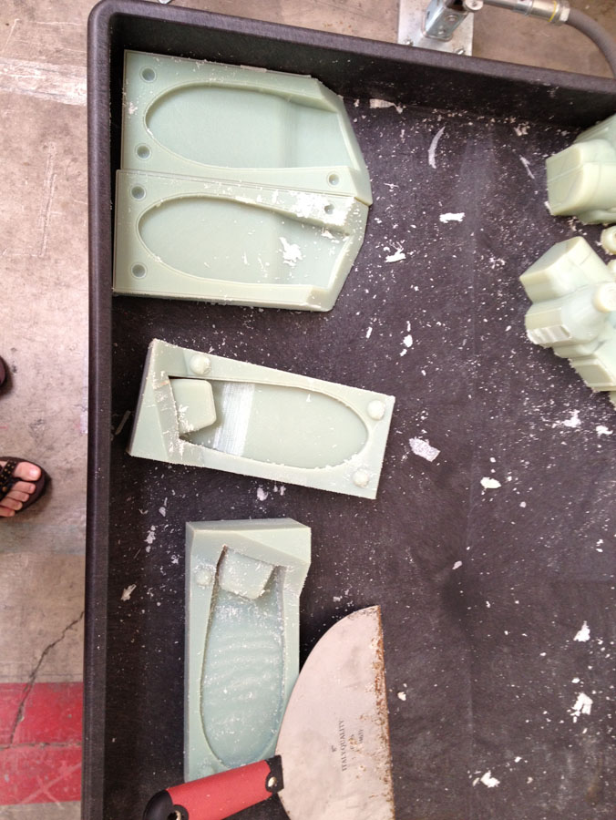
I was able to use a super fancy machine, the Objet Connex, which is simpler for the operator than most hobbyist machines (the tradeoff is, it's very expensive both for the machine itself and for the print material). I saved my completed mold in .stl format which many or most CAD software packages can export to. It basically converts your drawing from vector curves to a triangular mesh. At this point, too, if you have been working without distance units, you will need to decide on those (mm, inches, etc) so the .stl file knows exactly how big your object is.
The Connex basically just requires you to import your .stl file into its driver program, which if I can get a couple screenshots I will add here. You get an estimate of the time required to print, and of the amount of print material needed. The Connex handles undercuts by using a supporting material, which is a waxy substance that must be scraped and washed off the completed mold. There are many different printable materials the Connex can print, depending on the setup of the machine. I used their "ABS-like" plastic, as it is the most heat-resistant and my casting material uses an exothermic reaction to cure (in other words, it gets hot while setting).
The Connex basically just requires you to import your .stl file into its driver program, which if I can get a couple screenshots I will add here. You get an estimate of the time required to print, and of the amount of print material needed. The Connex handles undercuts by using a supporting material, which is a waxy substance that must be scraped and washed off the completed mold. There are many different printable materials the Connex can print, depending on the setup of the machine. I used their "ABS-like" plastic, as it is the most heat-resistant and my casting material uses an exothermic reaction to cure (in other words, it gets hot while setting).
Cleaning the Prints
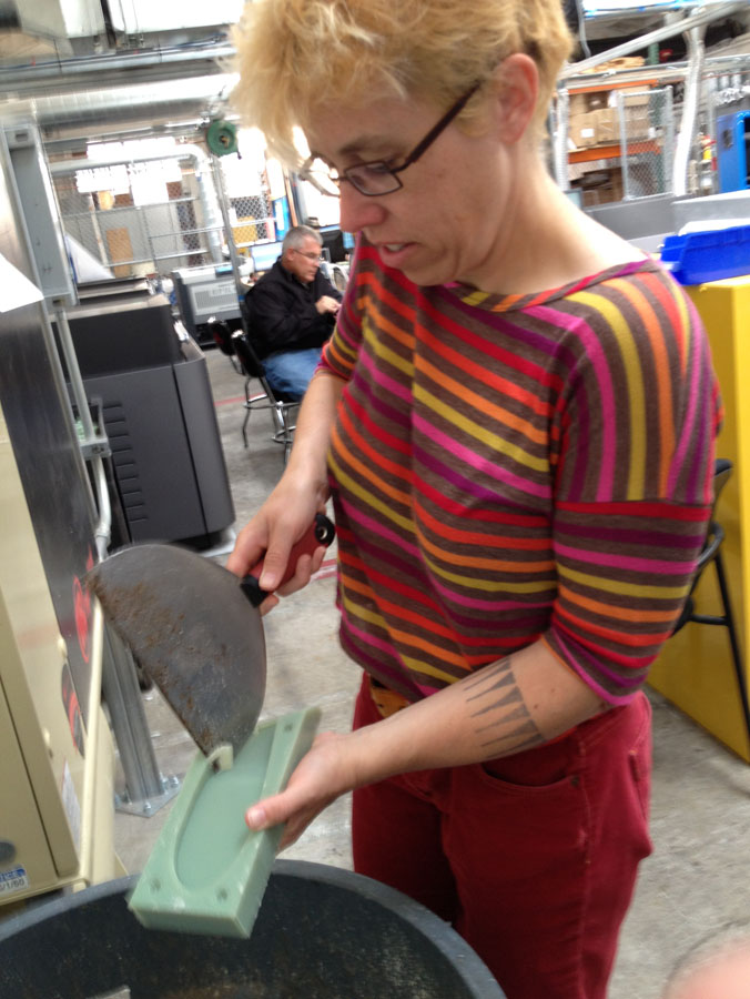
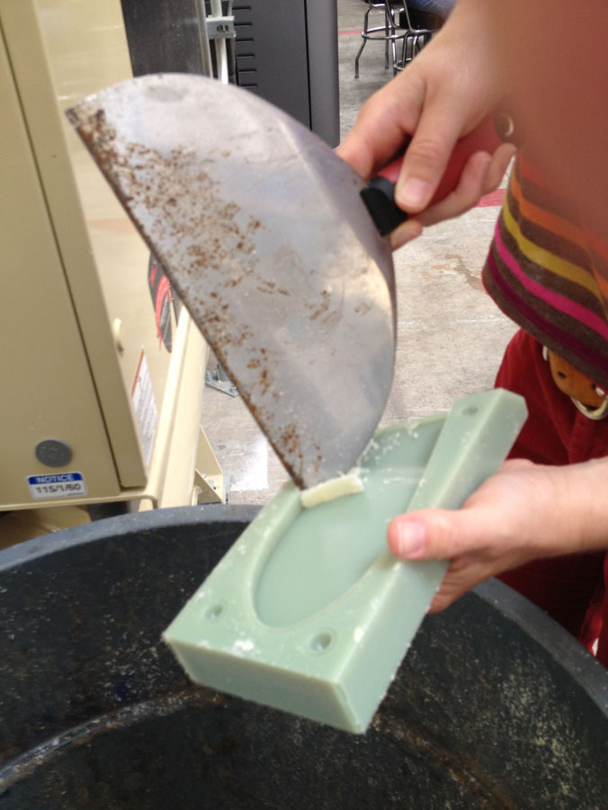
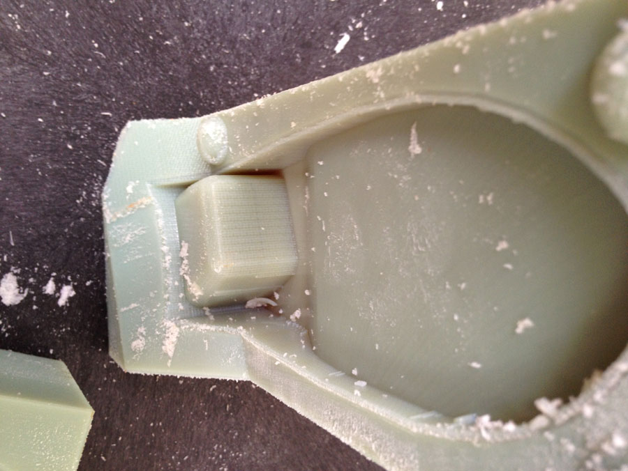
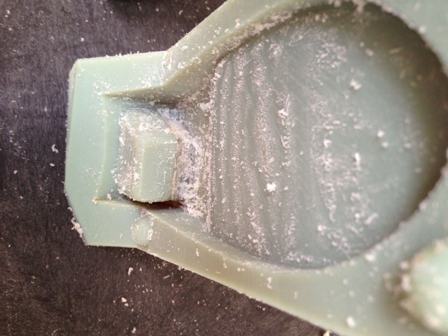
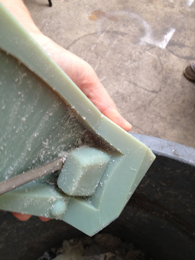
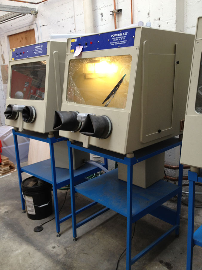
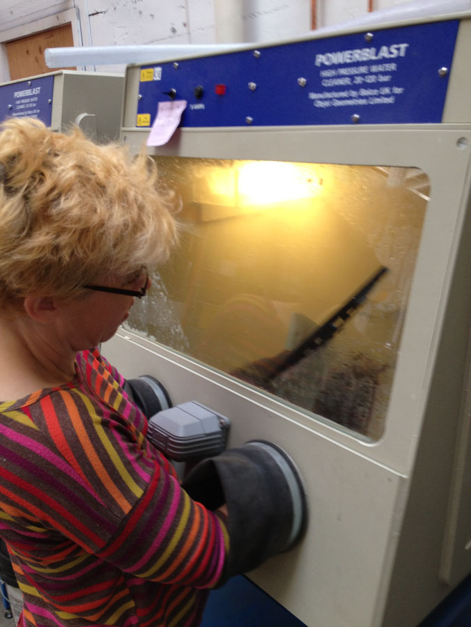
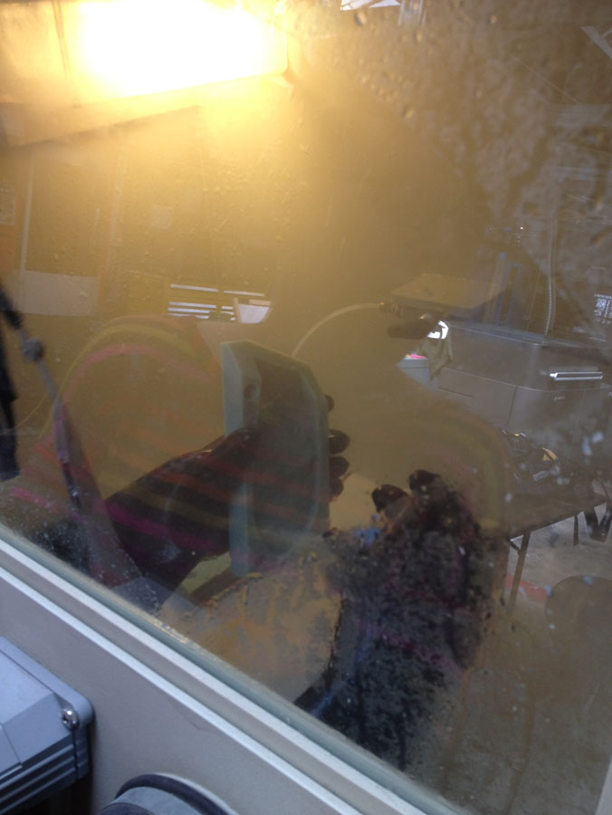
This step is just time consuming. Use a scraper of some sort to get the bulk of the supporting material off your mold, and wash the rest. A power washer is the recommended tool (and it's kinda fun, at least for the first few times) but a toothbrush and a bowl of water would also work fine. If you are using a printing service they will clean the print for you before shipping it out.
Finished Mold

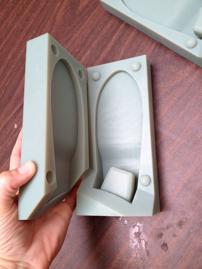
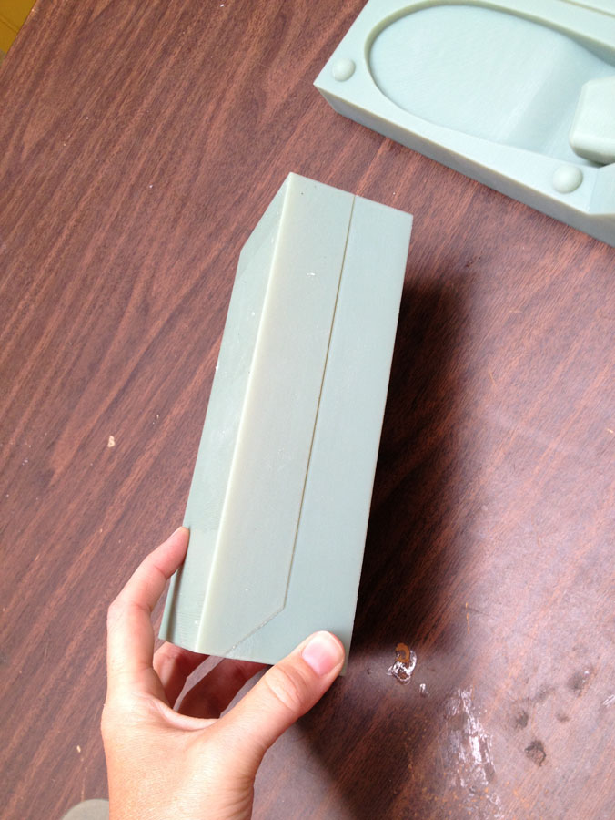
Once the prints have been washed and dried, they are ready to go. I was casting expanding foam and I did not need any further prep other than mold release; different casting materials might differ and I will surely do more experiments and write up my results.