Making Gummies From Your Video Game Mods on the Cheap
by Jetpack5 in Workshop > 3D Printing
2227 Views, 4 Favorites, 0 Comments
Making Gummies From Your Video Game Mods on the Cheap
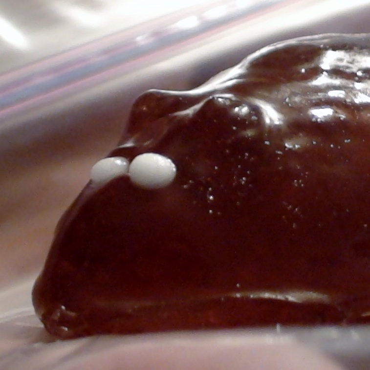
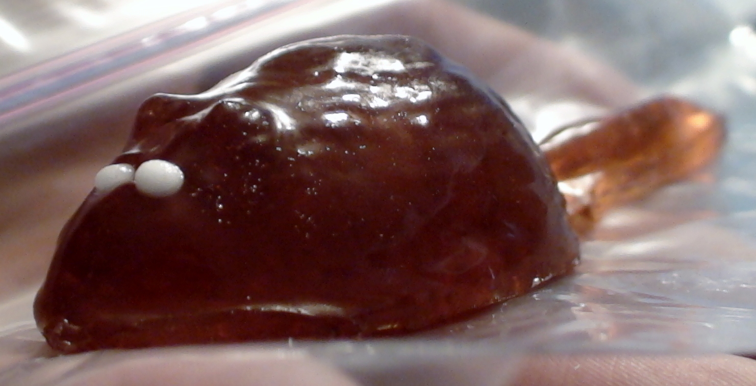
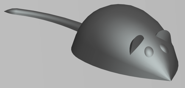
So, you just finished designing a sweet Water Elemental for Skyrim, Zombie Mook for Half-Life 2, Mutant Bunny for Fallout 3, or whatever other game will give this Instructable a lot of Google hits.
What better way to celebrate than with some tasty, tasty gummies?
And what better gummies to eat than your own Zombie Ninja Robot Kitten Assassin?
Problem is, you're on a budget and can't afford the latest in gummy-tech.
Not a problem!
In this Instructable we'll walk through the steps to prepare your model, transfer it to make a molding blank, form the mold, and make a gummy. You are on your own for how to enjoy them.
As a fan of The Elder Scrolls, I wanted to start with a good starting monster, the rat. Now it would be unfair to just rip off their model, so I made my own spin on it as a fun cartoon mouse.
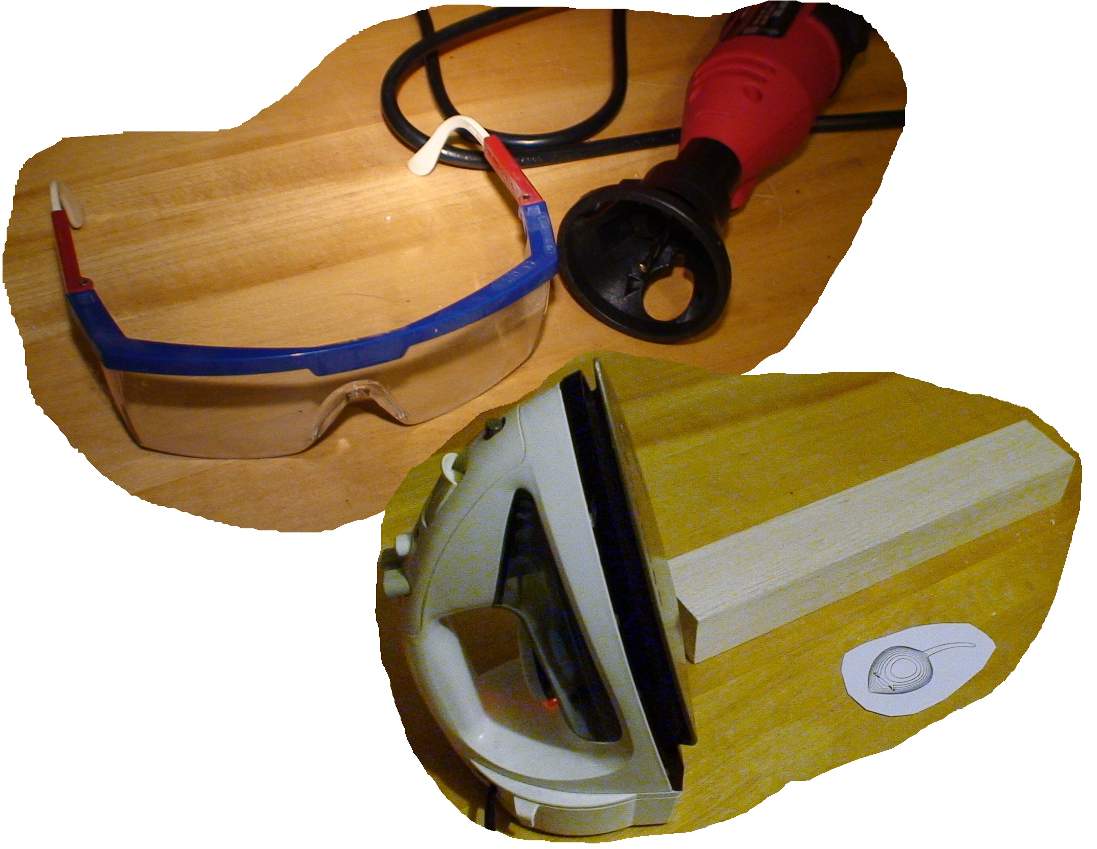
Once you have your idea, you will need the following tools (or equivalents) (see the last image):
- A block of wood at least slightly larger in all directions than your model. I prefer balsa wood as it is inexpensive and easy to carve.
- Access to a laser printer or photocopy machine. In a pinch try the local library for a copier.
- An iron (the kind you use to iron clothes)
- Tape (masking, duct, Scotch, etc...)
- A wood cutting tool. I used a Dremel 565 Multipurpose Cutting Kit on my off-brand "Dremel Style" rotary tool. Alternates include:
- A router (or router attachment for your tool)
- A milling machine
- A router, end mill, or rotary tool cutting bit in a drill press
- Non-toxic acrylic paint
- Several bowls and spoons
- A paper plate
- Wire whisk or fork
- Corn starch
- A microwave
- Gummy candy in your favorite flavor (any shape)
- Light food oil (olive, vegetable, canola, etc...)
- Pearl nonpareils or other decorations
Download Your Software Tools
In the next step we will be slicing the model. Slicing creates a series of contours from the part along parallel planes. This makes a mapping like a topographic contour map. We will use the contours to guide our cutting of the blank.
Slicing is used extensively in Rapid Prototyping. STL files were in fact developed for use in Stereolithography, a type of rapid prototyping. Slicing programs are fairly common, including a few Freeware or Open Source applications.
Since we are working in the cheap here, free software is our friend. In particular we will be using two programs:
- MeshLab (http://meshlab.sourceforge.net/) will be used to process the mesh file. It is critical here that you do not use the latest version right now as the slicing function is buggy. You will need to use version 1.2.3, which can be found here: http://sourceforge.net/projects/meshlab/files/meshlab/MeshLab%20v1.2.3/
- Inkscape (http://inkscape.org/) will be used to process the resulting contour file.
These are both really useful programs. These give up the options we want with the minimum of fuss and cost. We hardly touch the surface of their capabilities. After you are done here, I encourage you to get more familiar with these great systems.
Shapes for Casting: Don't Dodge the Draft!
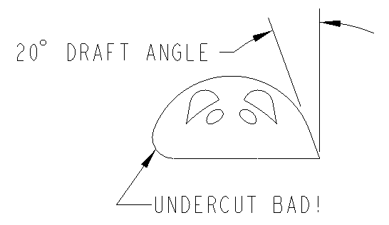
We are going to be casting the gummy part. Casting is a process where a hot liquid is poured into a cavity and allowed to cool to a solid. Designing a good cast part requires some thought to your design. The Draft Angle and the Base are important features for your part.
The Draft Angle is the mount that your part angles away from a vertical wall (see the figure). When you have negative draft you get an Undercut. There are techniques that can be used to cast parts with undercuts but these are for the advanced class. Undercuts are bad because they prevent you from removing your blank from the mold intact. In fact even a vertical wall will tend to hang up on your mold and cause problems. You need a minimum draft angle of 5 degrees, but more is better. Draft angle applies to every surface of the part. Notice in the figure that the ears of the mouse also have a draft angle also. Many CAD systems have tools to measure draft angles that you may find useful to check your part.
The other reason why you need to have no undercuts in your part is that you will be carving the part from above. You will not have a way to cut an undercut layer without a lot of additional work (which would be wasted since it would mess up your mold anyways).
For simplicity our mold will be an open mold with a single half. Your part will have to have one flat surface as the Base. This will be the top of your mold cavity where you will pour your melted gummy. The base surface will be the largest surface of your part. Generally this will be either the back or bottom of your part.
With these considerations you will need to modify your original model. Your model in the game will no-doubt be a full round figure with plenty of undercuts. You will need to make a copy of your model and add or modify features to eliminate undercuts and create a good base surface.
Creating a Mesh
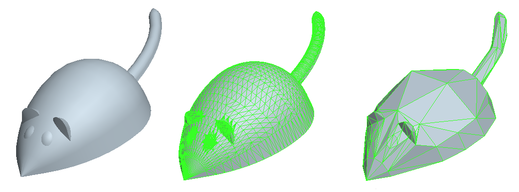
The source of the model is really up to you. Ideally the best models are made yourself. The end goal for us is to make the needed "mesh files".
While most CAD systems work with files that have arbitrary geometry: smooth surfaces, curves, flat panels, etc... This gives us a lot of functionality since we can create essentially any shape. However this is overkill for your average video game. To improve processing the shape is split into a set of polygons called the mesh.
3D CAD is my favored tool for creating new models. Everyone has their own favorite and choosing a CAD package is beyond the scope of this Instructable. If you don't have one, definitely go check out Autodesk 123D. It will be necessary to convert your file to a mesh. All decent CAD packages can save to mesh files, generally using a Save As command. For our purposes a .STL or a .OBJ file format are fairly standard meshes.
Autodesk 123D has a handy gallery if you need inspiration.
If you already have made your mod, you may have to convert your game file to a different format. If you are making files for Oblivion, Fallout 3, and several others the information is in a .NIF format. Fortunately this helpful Wiki has information on a great tool called NifTools that will allow you to view the data in the NIF file and can export it to a mesh as an OBJ file. For other games you'll have to consult your documentation.
Not all meshes are created equal! Game designers have to make a balance between a low polygon count giving faster rendering and a high polygon count for better appearance. When making your model, more is better. A high polygon count will result in a much smoother part. Fortunately, as game systems get better the models in the game get higher polygon counts. See the figure for a comparison of polygon counts. If your model is more blocky than you like you will have to load it into an editor to make adjustments. We will be using a piece of software called MeshLab for the processing of the mesh, which has some tools for smoothing the mesh if needed.
There are many other sources of mesh files. A quick search on Google will find many galleries of mesh files. If you have access to a 3D scanner then you could use real objects as the basis for your model. I have to put in a plug here for the research being done at my alma mater, IIT, on 3D Scanning. If you are really hard up you could search through the mesh files of your favorite game for inspiration.
Sliced Mouse!
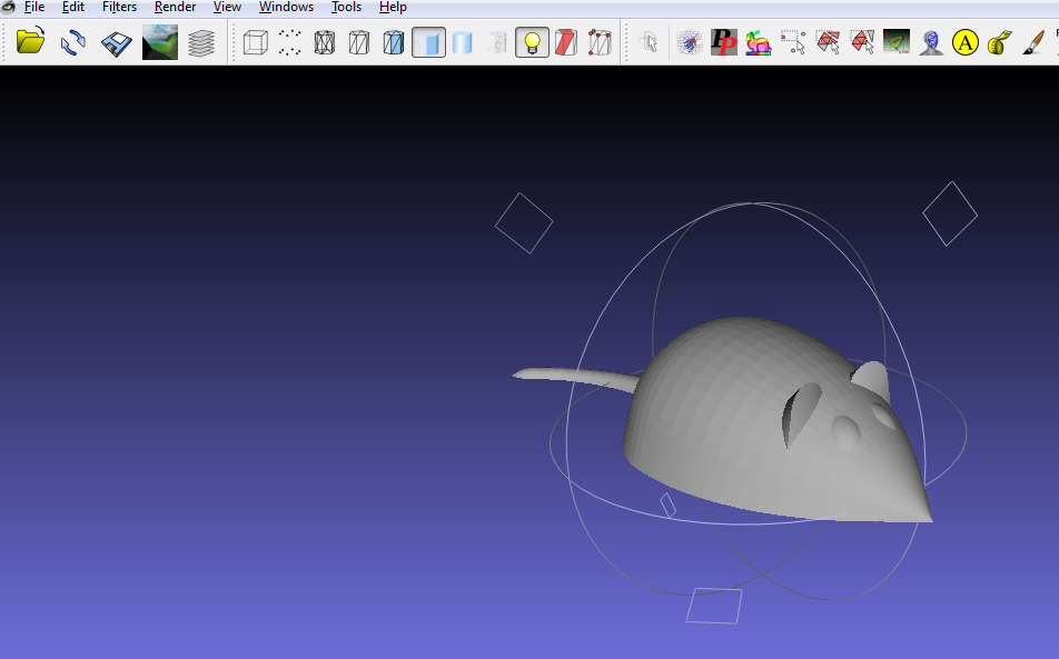
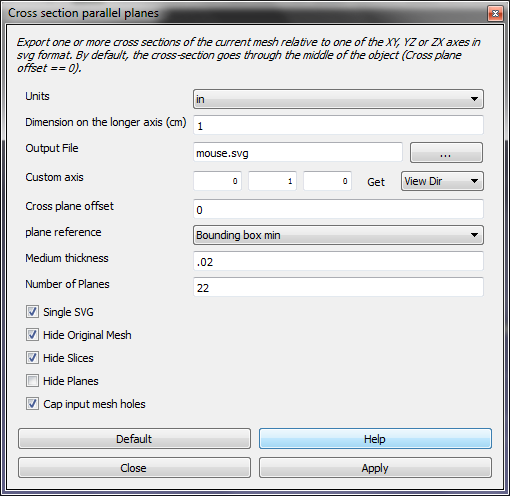
First, start up MeshLab. It will ask you to load your mesh file. It may ask for some processing options that you should perform. We will use Meshlab to convert the mesh file to a series of contours as a SVG format file.
I tried to include screenshots of each step in this process.
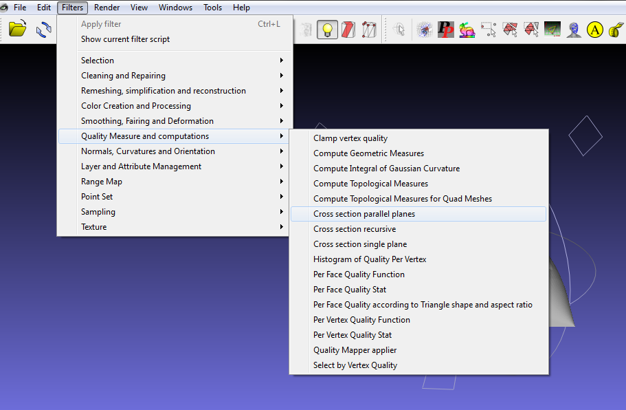
The slicing tool is located in the menu Filters > Quality Measure and computations > Cross section parallel planes.
You will need to do a little math here. You will need to decide how tall your part will be, how thick the slices, and the number of slice layers for the part. This is a balancing act. If you use more layers you will have a smoother part, however you will have more layers to cut and they will be harder to tell apart when cutting. You will also have to decide the overall length of the part, which will be used later.
For this part I decided to make a 0.75" tall part with 11 layers, giving a layer thickness of 0.075", which seemed reasonable. I decided to specify 22 layers for slicing and discard every other layer. This avoids possibly having a funky first or last layer.
In the dialog, select the default parameters first, and then put in your custom parameters:
- Units: This doesn't matter as we will override the units later, so leave it as CM
- Dimension on the Longer Axis: We will override this also later, so I set it to 1
- Output File: This does not seem to matter. The software always seems to use the same file name as the source file, changing the extension to .SVG.
- Custom Axis: This set defines the slicing direction. For my part the "Y" axis is the vertical axis for my part, so I set that to 1 and the rest to 0.
- Plane Reference: Set this to Bounding box min. This is important to set the point where the first slice is located.
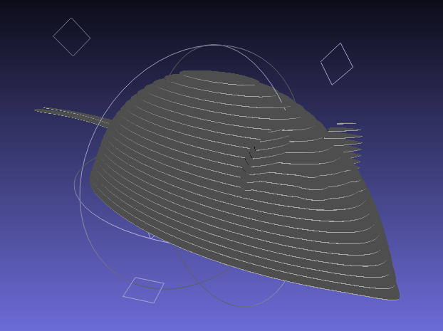
- Medium Thickness: This is a cosmetic value and will control how thick the slices are shown in the preview screen. It has no effect on the output file. I set it to .02 for visual purposes.
- Number of Planes: This is fairly self-evident. As we decided earlier, I used 22 slices.
The remaining options stay at default. Hit "Apply" and then "Close". You can preview the results as shown in the last screen shot. You can close MeshLab now.
Mapping Out the Blank
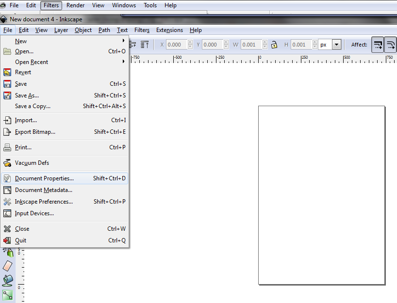

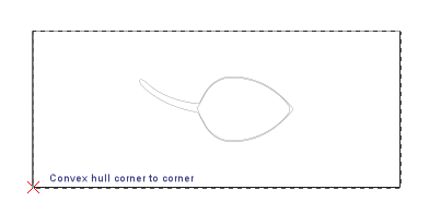
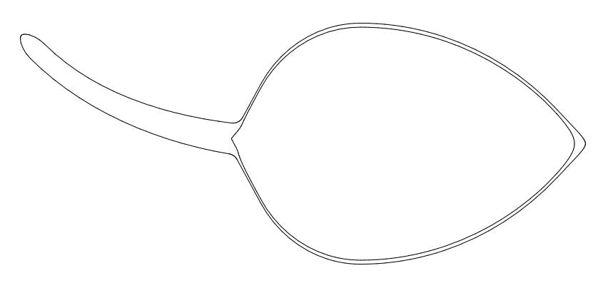
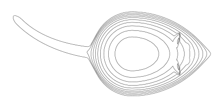
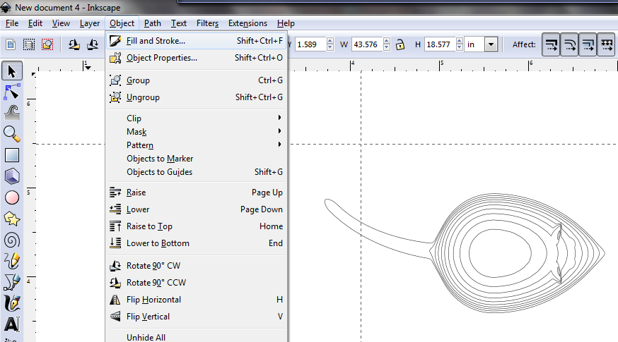
MeshLab has now generated the contours in a SVG file, but the contours are not necessarily scaled and are not assembled into a single contour shape. For that we will need to use Inkscape.
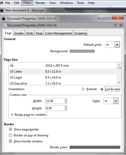
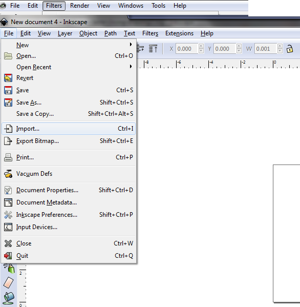
You can optionally open the generated SVG file directly or start up Inkscape and import the SVG file into the new document. In either case you will need to set up the document for your paper size. In the File menu select Document Properties.
Set the Default Units to your favored set, I prefer inches.
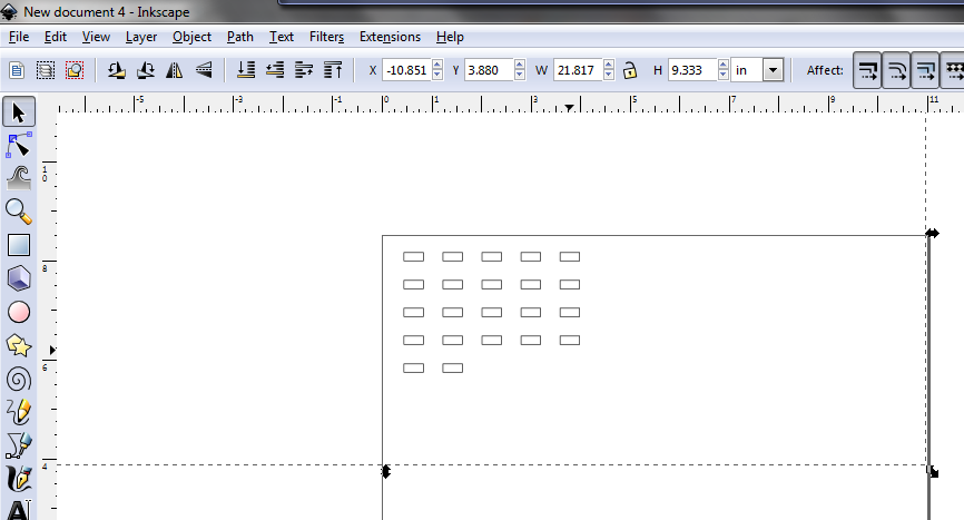
If you didn't open the SVG file directly, select Import in the File menu to import your SVG file.
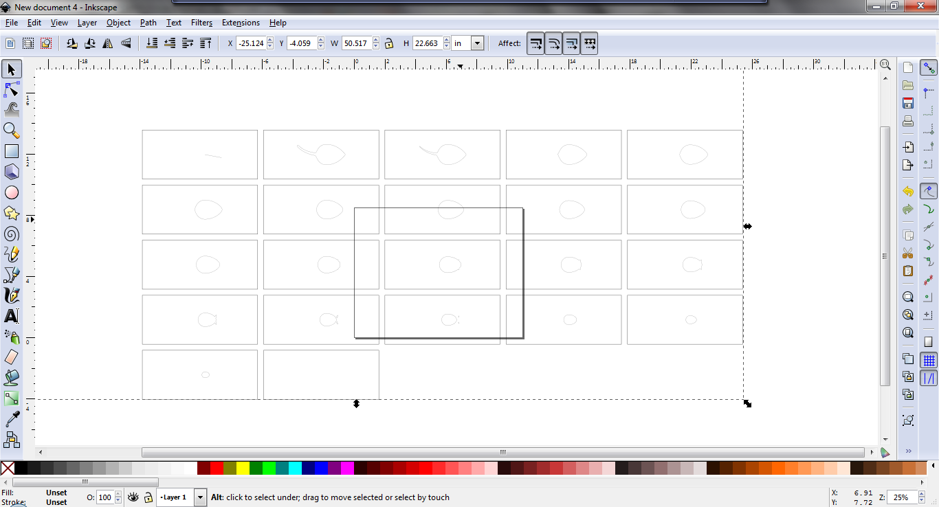
You may notice that the contour files are set up in array. The first contour sometimes will be spoiled, so in that case we can use the second contour. If all of the contours are spoiled, check your slicing setting in the previous step and try again.
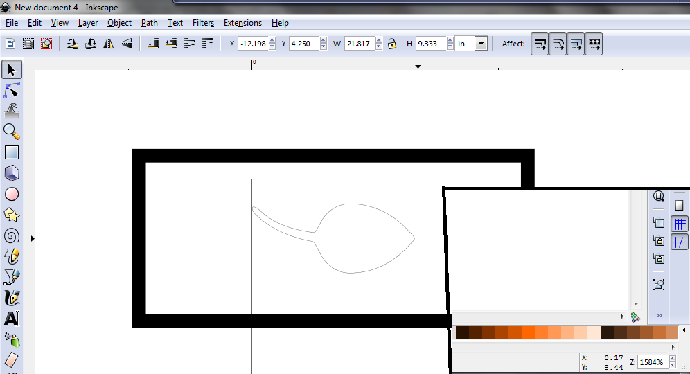
Also, the contours are not scaled. Pressing Ctrl-A to Select All, drag the first good contour into the upper left corner of the document so that you can measure it with the ruler. For the mouse I want to scale it so that the overall length is 2.5 inches long. In order to get a better measurement I place the tail on the left edge of the page and hover the cursor over the nose of the mouse. In the lower right corner the window Inkscape shows the cursor position, giving a more accurate measurement than the ruler.
In this example the Current Length is 0.17 inches.
Now get out your calculators again and calculate the Scaling Factor you will need. The Scaling Factor is the Desired Length divided by the Current Length multiplied by 100%.
SF=DL/CL*100%
For out part this is: 2.5/0.17*100%=1470%
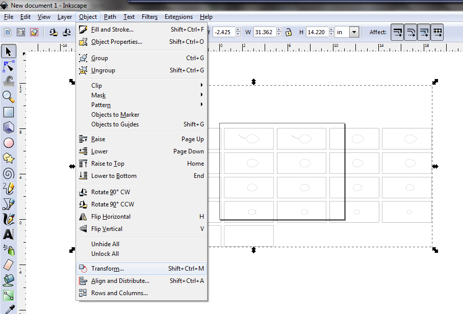
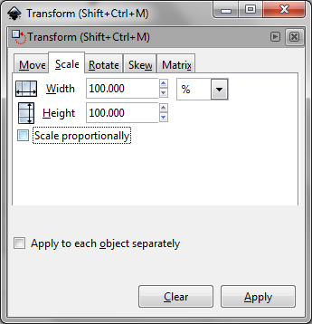
In the Object menu select Transform to pull up the transform dialog. Select the Scale tab and set the Width and Height values to your Scaling Factor and press Apply.
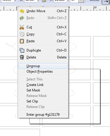
Select the set of contours and select Ungroup from the Edit menu.
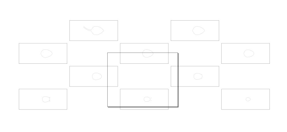
Since we set MeshLab to make twice the number of slices that we need, select and delete every other contour.
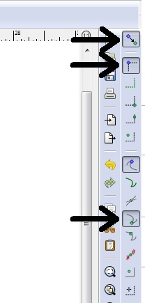
Now is the time to consolidate the remaining contours into a single topographic mapping. The boxes for each contour act as a reference. You will want to Enable Snapping by ensuting the enable snapping button is enables in the right hand toolbar (see the 12th figure). Also toggle on the Snap Bounding Box Corners, Snap Nodes or Handles, and Snap to Cusp Nodes selectors. This way the corners of the boxes will snap to each other. Remember that the boxes and contours are separate objects. You will need to hold down the Shift key to select both (this is unlike normal MS Windows operations; selecting Ctrl has a different function).
When all of the contours are assembled, delete the bounding boxes.
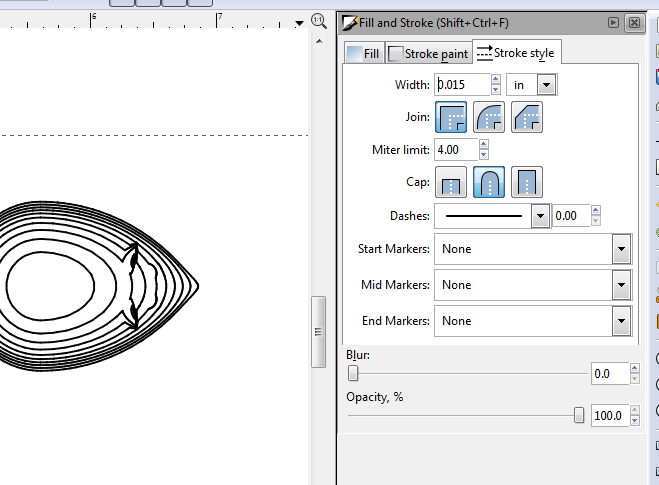
It may be necessary to adjust the line thickness of the contours. Use Ctrl-A to select all objects. In the Object menu select Fill and Stroke to pull up the line properties dialog. In the Stroke Style tab, make adjustments to the Width value. This will be a balance where a thin line will be more difficult to see the individual lines but thicker lines will overlap.
In the transfer process your image will be flipped, so if orientation is important (e.g. text) then you will need to use the Object menu to apply the Flip Vertical or Flip Horizontal command.
You are now set to switch from virtual to physical. Save your work and print a copy of the contour file.
Transferring the Pattern
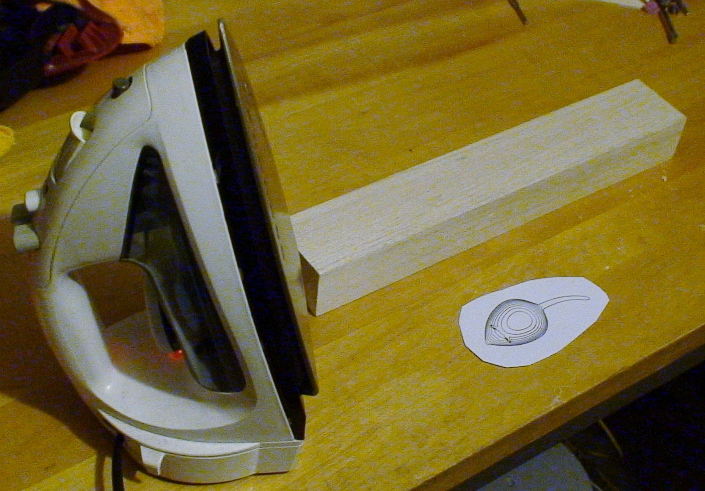
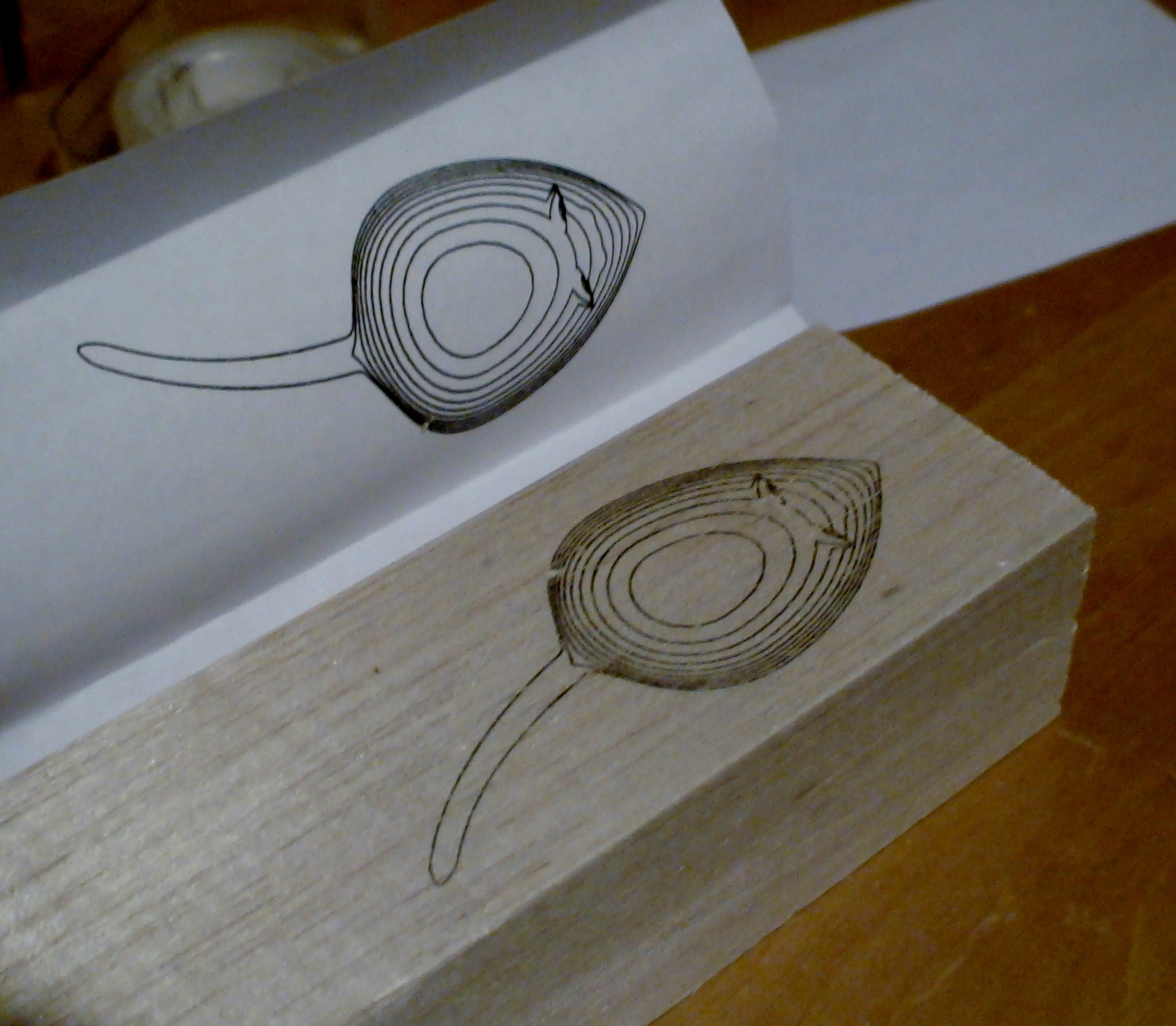
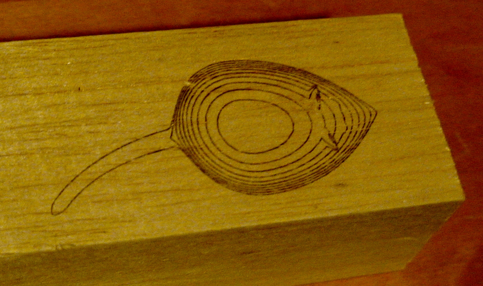
For this step it is essential that your transfer design is printed with a laser printer or photocopier. If you have an inkjet or other printer you will need to make a copy of your pattern on a photocopier (if you use a printer/copier it must use a laser printer). In a pinch your local copy shop or library can be used. But your transfer pattern to a manageable size.
The reason for this requirement is that photocopy machines and laser printers use heat to fix the powdered toner to the paper. We will use that same property to fix some of the toner to the wood block.
Set your iron to it's high heat setting.
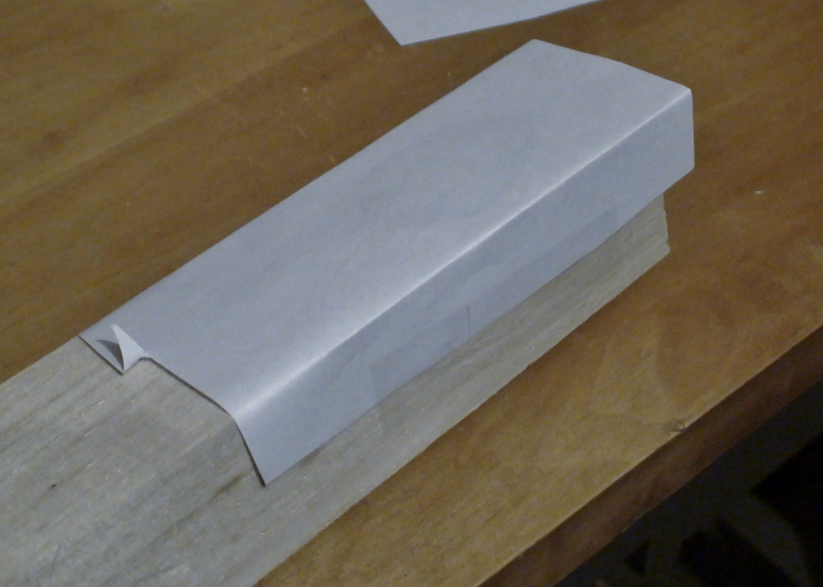
Use the tape to fix your transfer pattern to the block with the ink side facing the block. It will be helpful to tape the paper in such a way that you can lift one corner to check that the transfer was complete.
With the hot iron, carefully iron the paper onto the block. Be sure to iron the entire surface to make a complete transfer. Ironing more will not hurt. Carefully lift one corner to check that the transfer is complete and replace and re-iron if needed.
Carve the Pattern
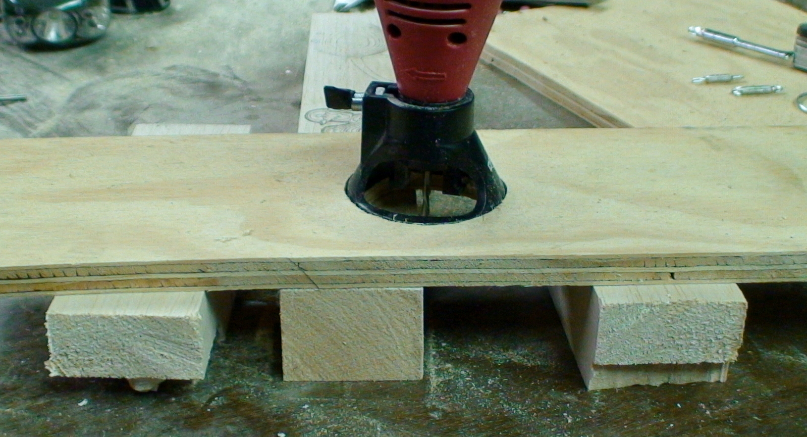
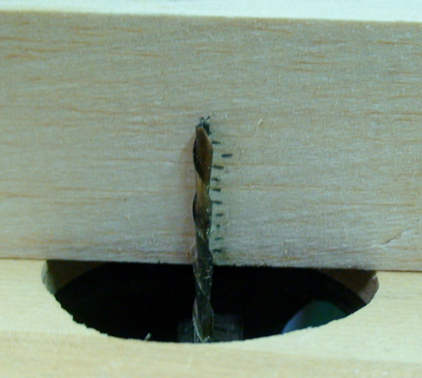
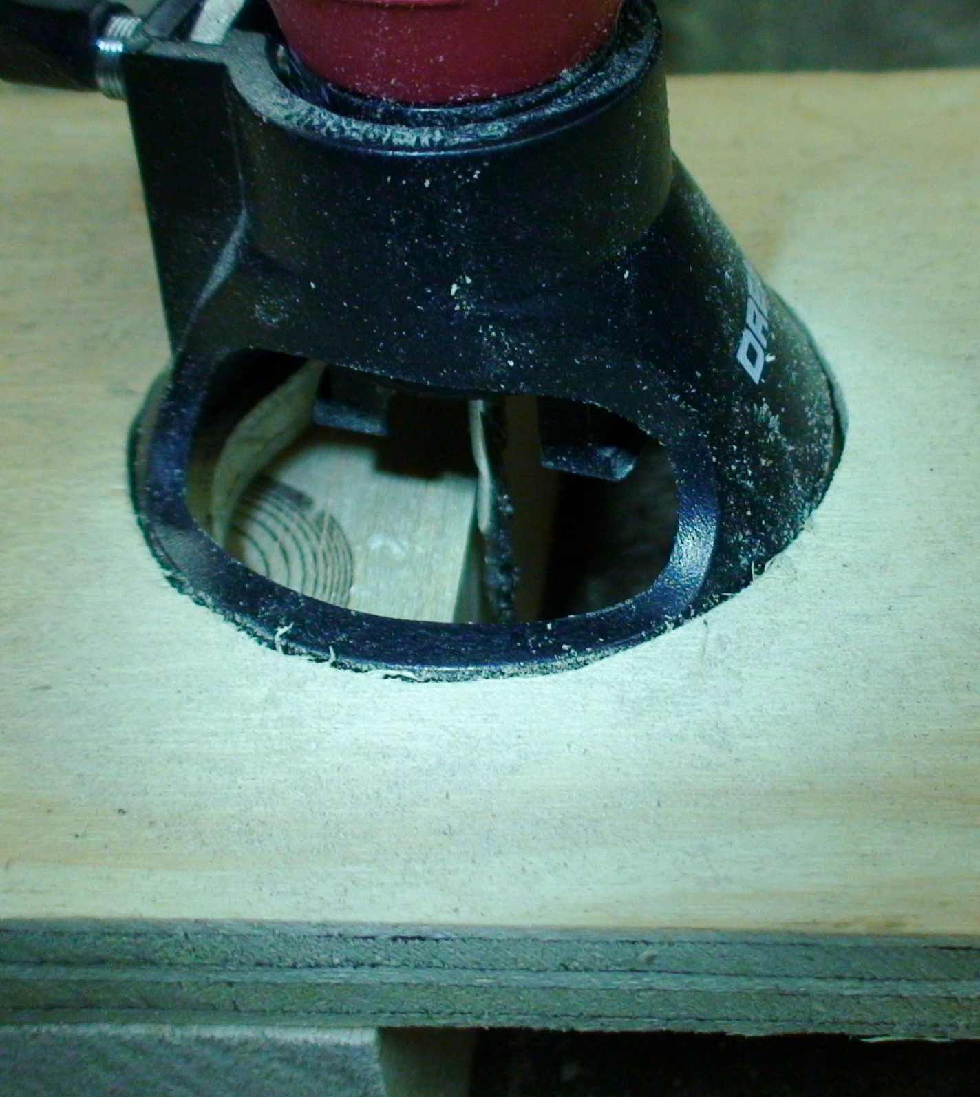
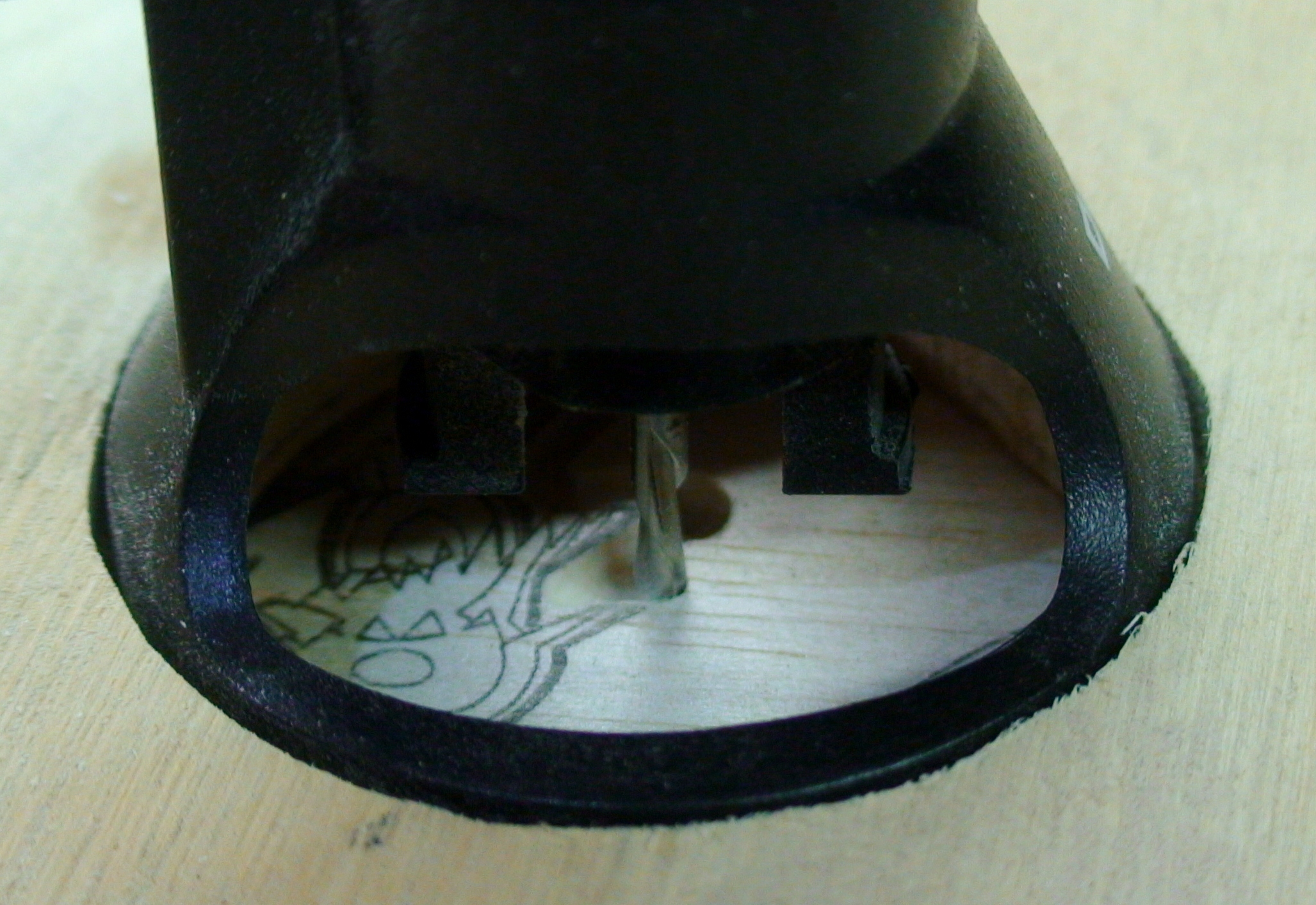
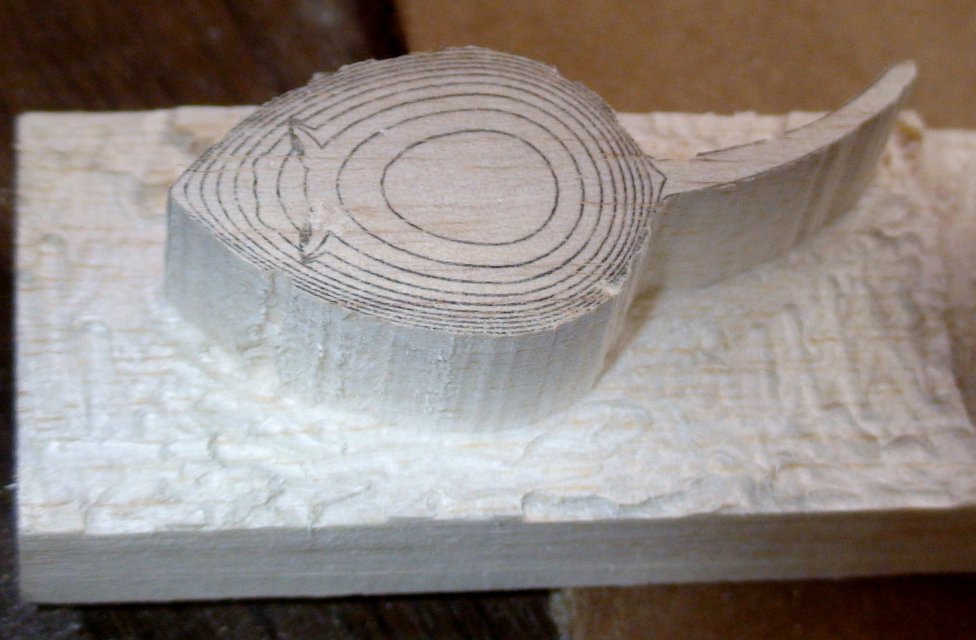
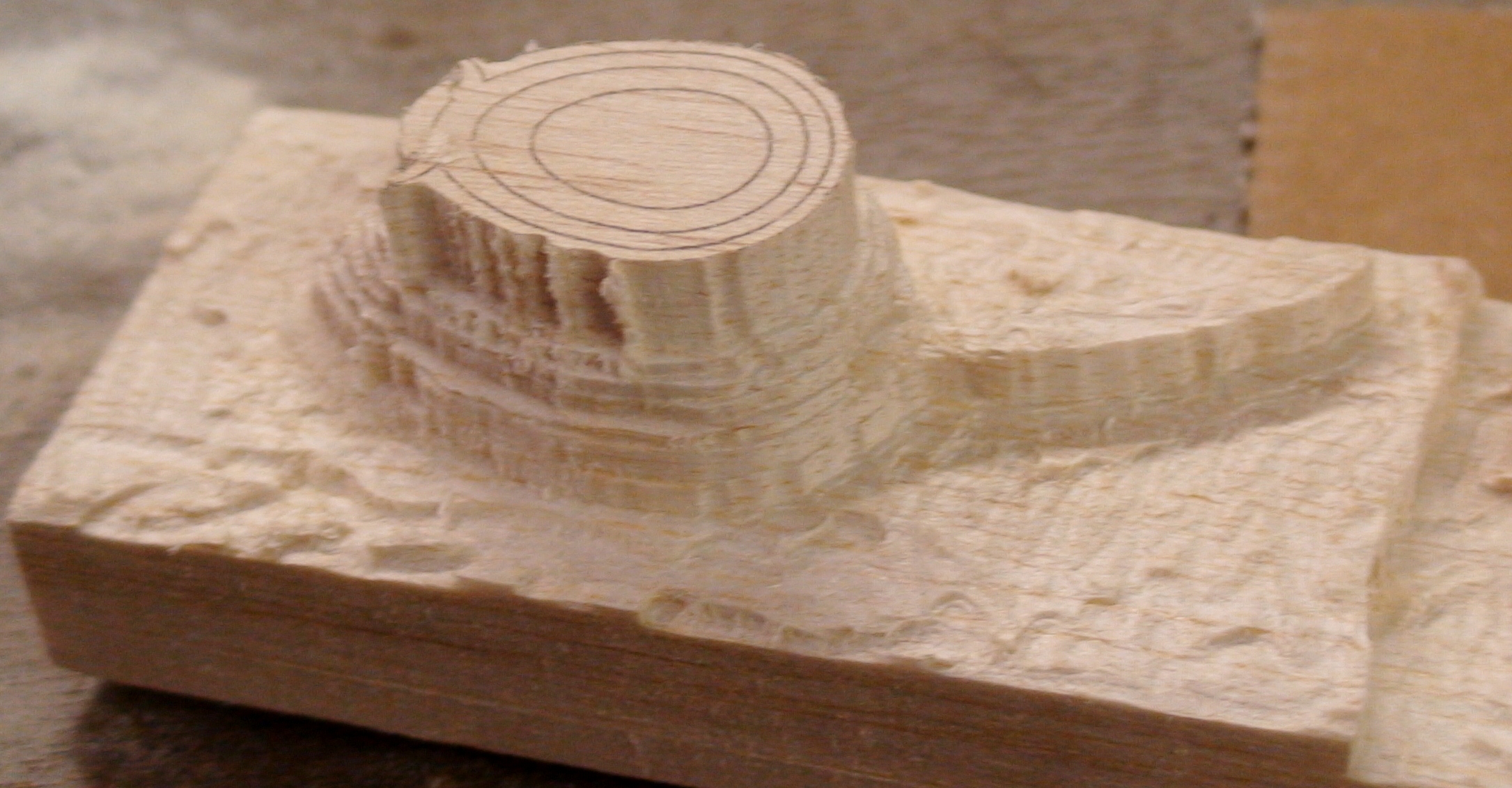
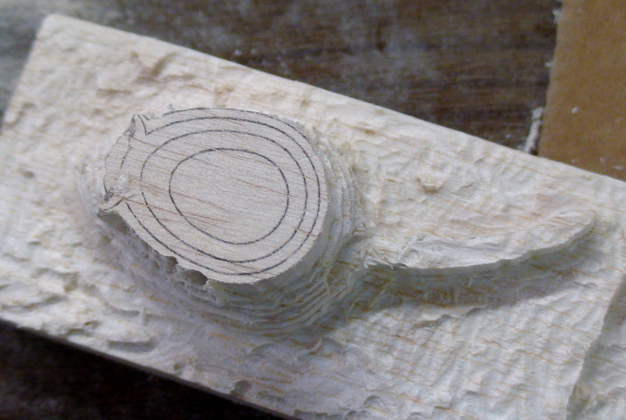
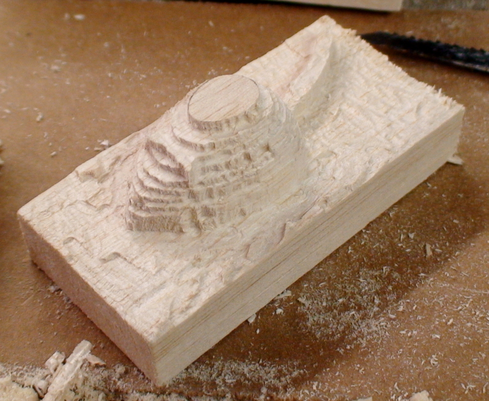
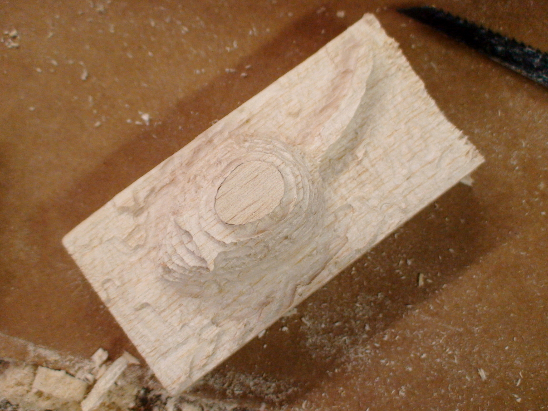
The cutting kit attachment has a relatively small ring and with the size of my block I needed to create a cutting jig. I cut a hole and pocket into a piece of 1/2" plywood and placed this onto two pieces of wood slightly taller than my block. This allows me to hold my cutting bit depth well. The rotary tool is held stationary and I move the block along the table.
I also made marks on the side of my block as depth guides. You may remember the Layer Thickness and Number of Layers you calculated previously. The marks are spaced with the same spacing as my Layer Thickness (0.075 in.) and the same number of marks as the Number of Layers (11) in my part.
Now would be a good time to put on safety glasses. Take care with these tools.
For the first cut, you will set the depth of the cutting bit to the lowest layer. You will start by cutting the outermost contour. Be sure to be careful when cutting, your bit can grab the part at awkward moments and gouge into your part. Working with the part to get precise cuts will require practice and patience.
Once you have the complete outer contour, carve out the area around the part to make a level around the part.
Now set the depth to the next more shallow level. Carefully come in and carve out the second contour.
Repeat this until all the contours have been carved out.
There are a few important tips to follow:
- Be patient and take care with these contours. The but may still tend to catch and gouge.
- Take care with your contours. It is very easy to get onto the wrong contour.
- This is especially true for complex shapes or for close contours for near vertical walls.
- If you do make a mistake, you will have to either incorporate the mistake or start over again.
- Take your time. This is the longest and most tedious step.
- Trust your pattern. You may not be able to see the full shape while making the contours but if you follow them you will be fine.
Post-Processing the Blank
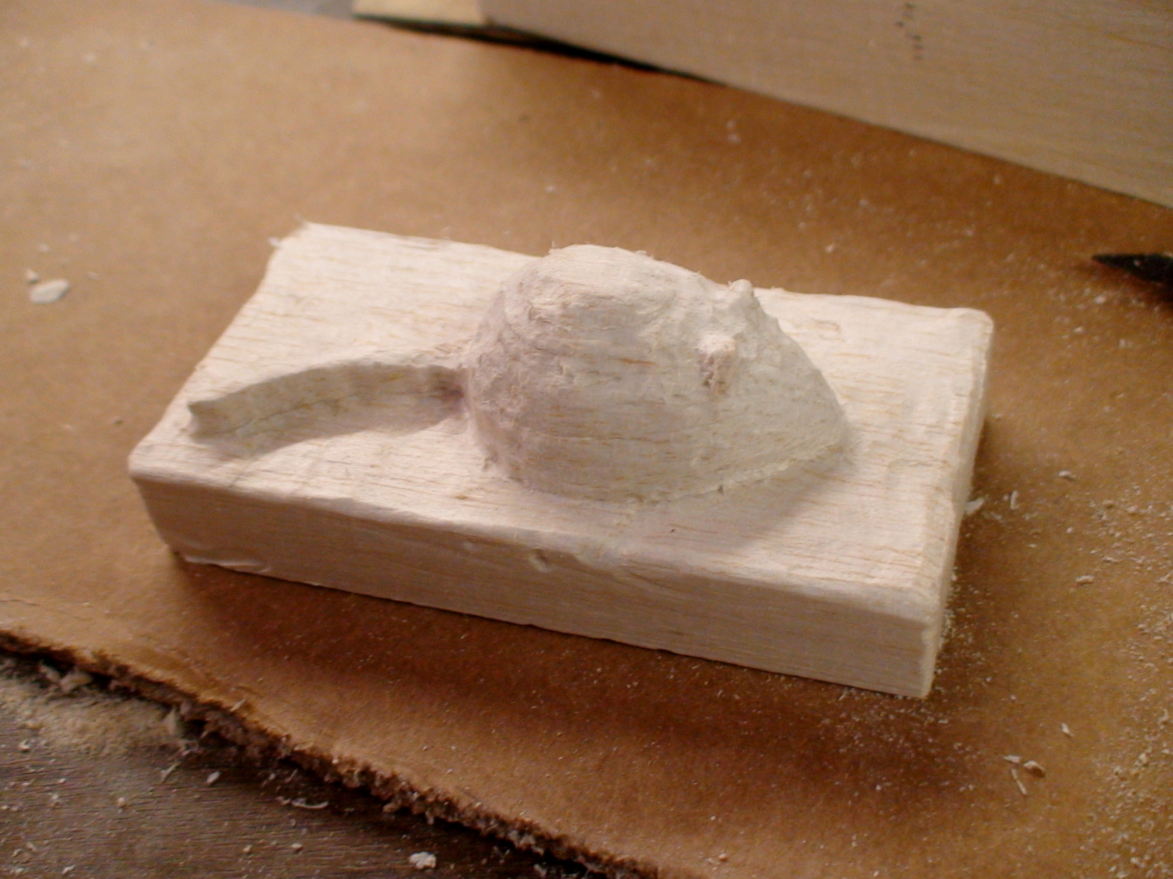
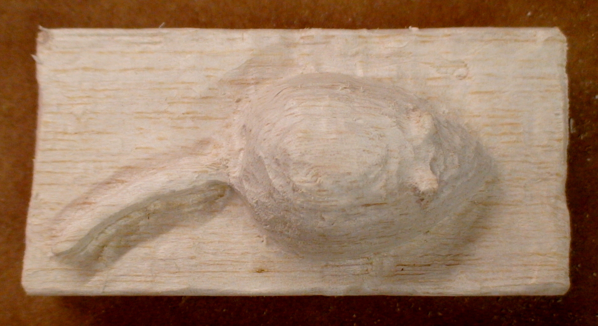
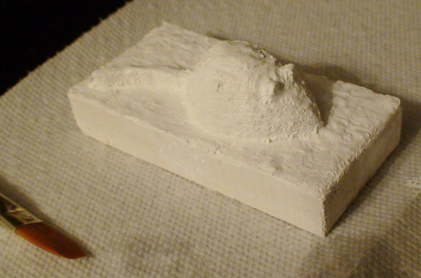
You will notice that your part has a "stair step" effect to it. If you like this effect then excellent, but this is generally considered a bad thing. The more layers you use and the smaller your layer thickness the less this will be prominent.
In any case, you will want to sand your part to try to remove any rough edges or splinters. Ideally you will sand down the part to reduce or remove the stair steps. I generally use the root of the stair steps as a guide for sanding. While you have your rotary tool out, the sanding and grinding bits work well for this.
It is also a good idea to seal the part surface. For this purpose use a non-toxic acrylic paint. Nobody will see the painted blank so use any color that is convenient (nobody will know that you bought that strange greenish color on accident). Paint several layers for good coverage.
Casting the Gummy
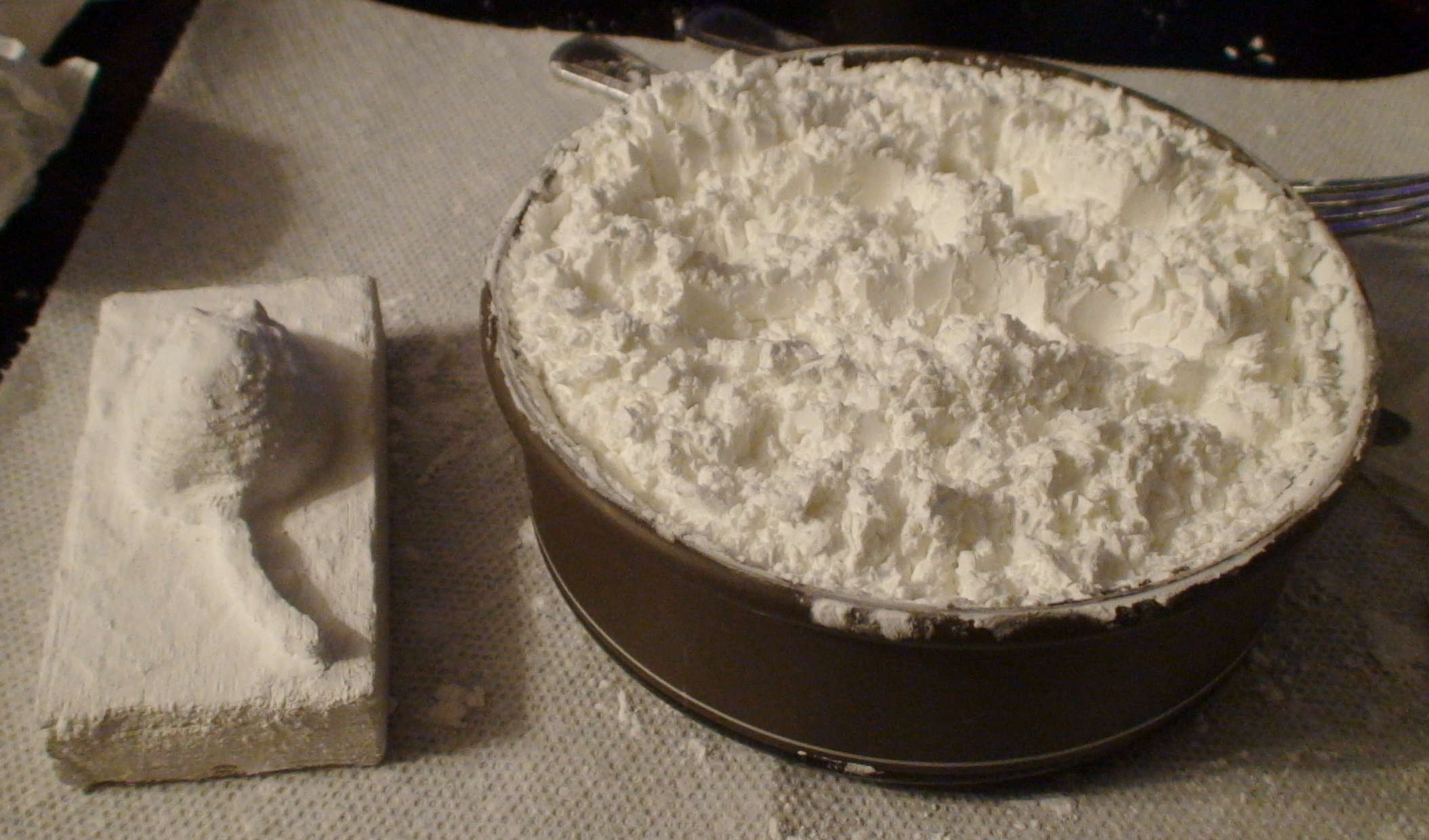
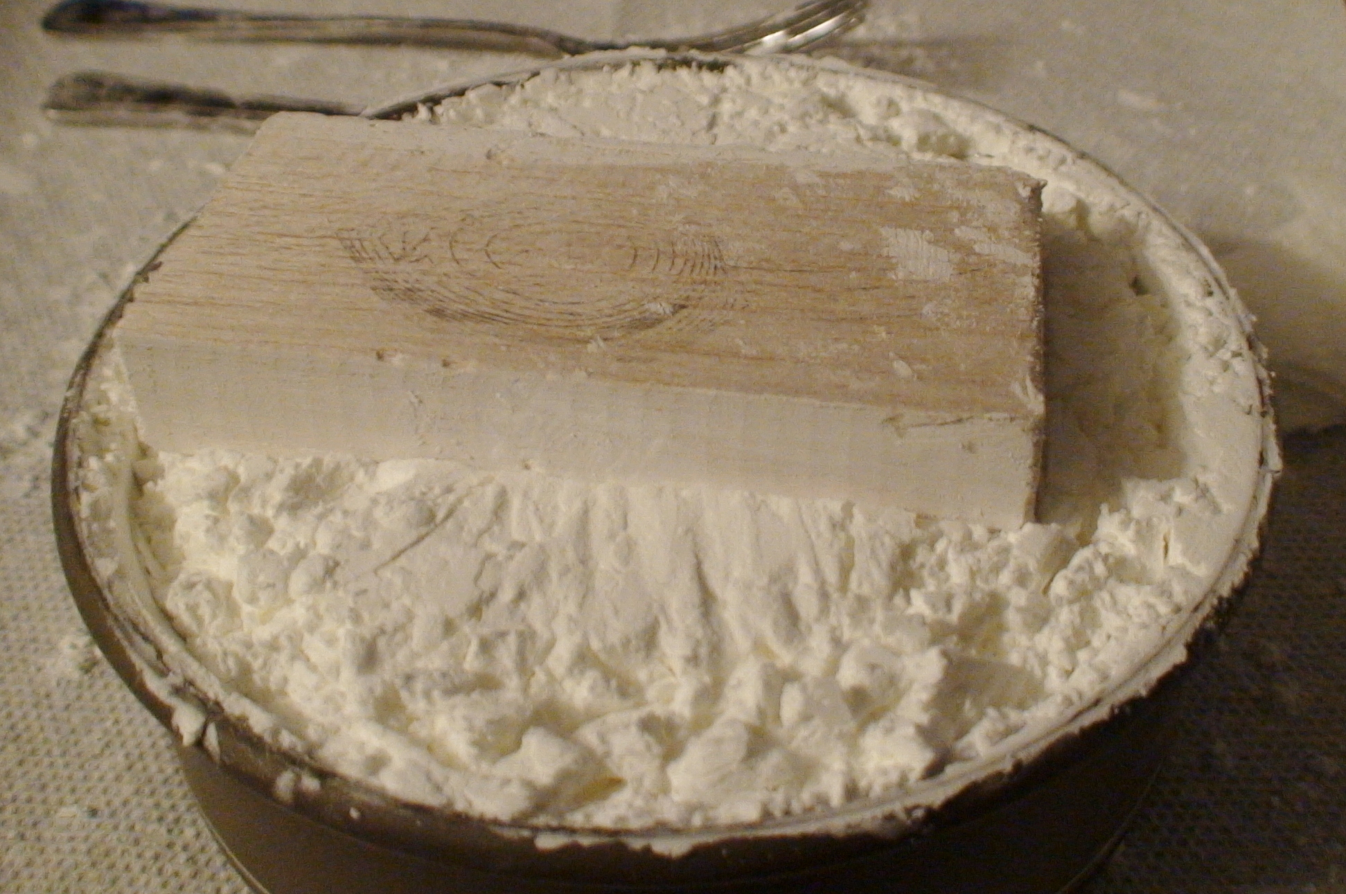
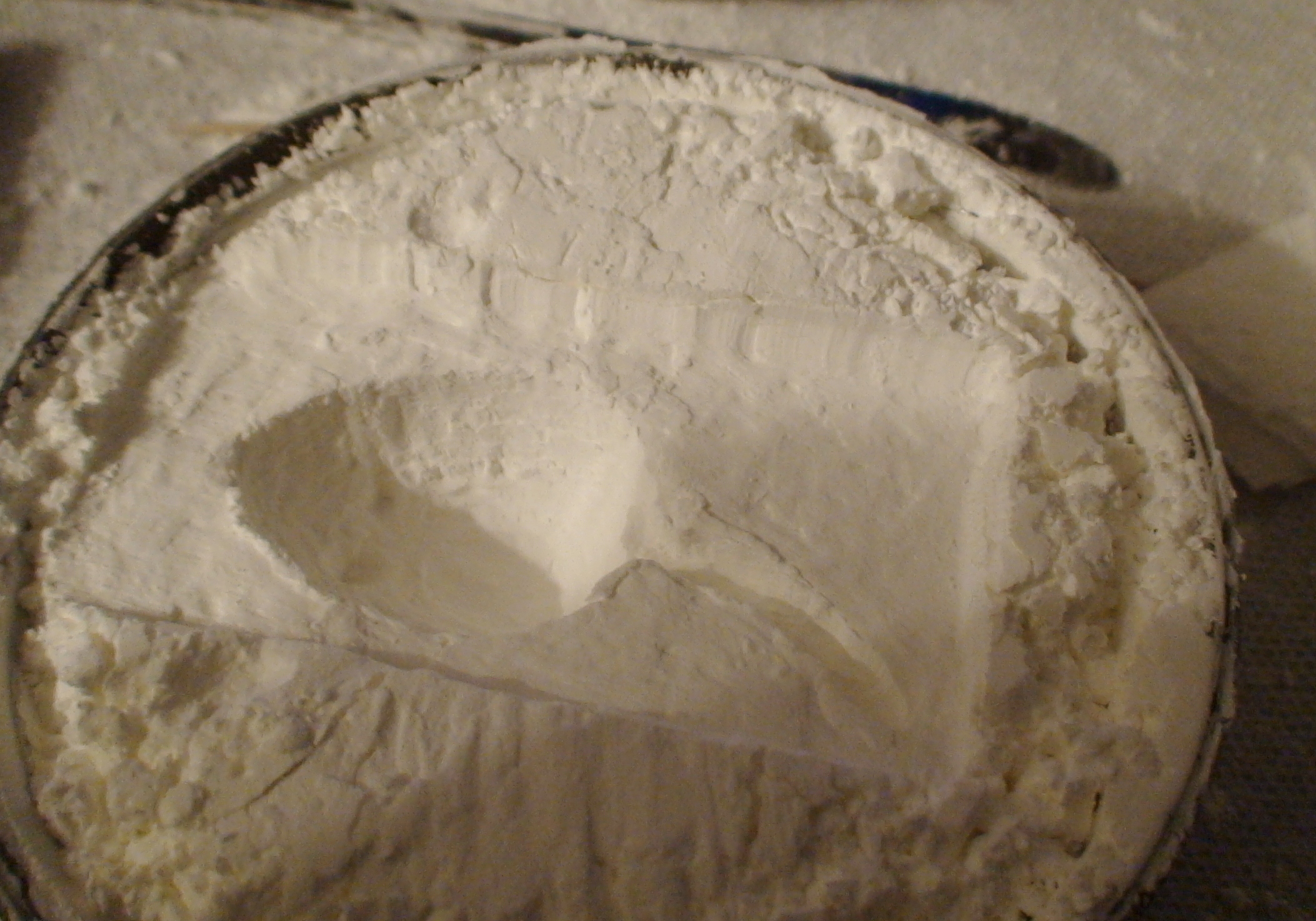
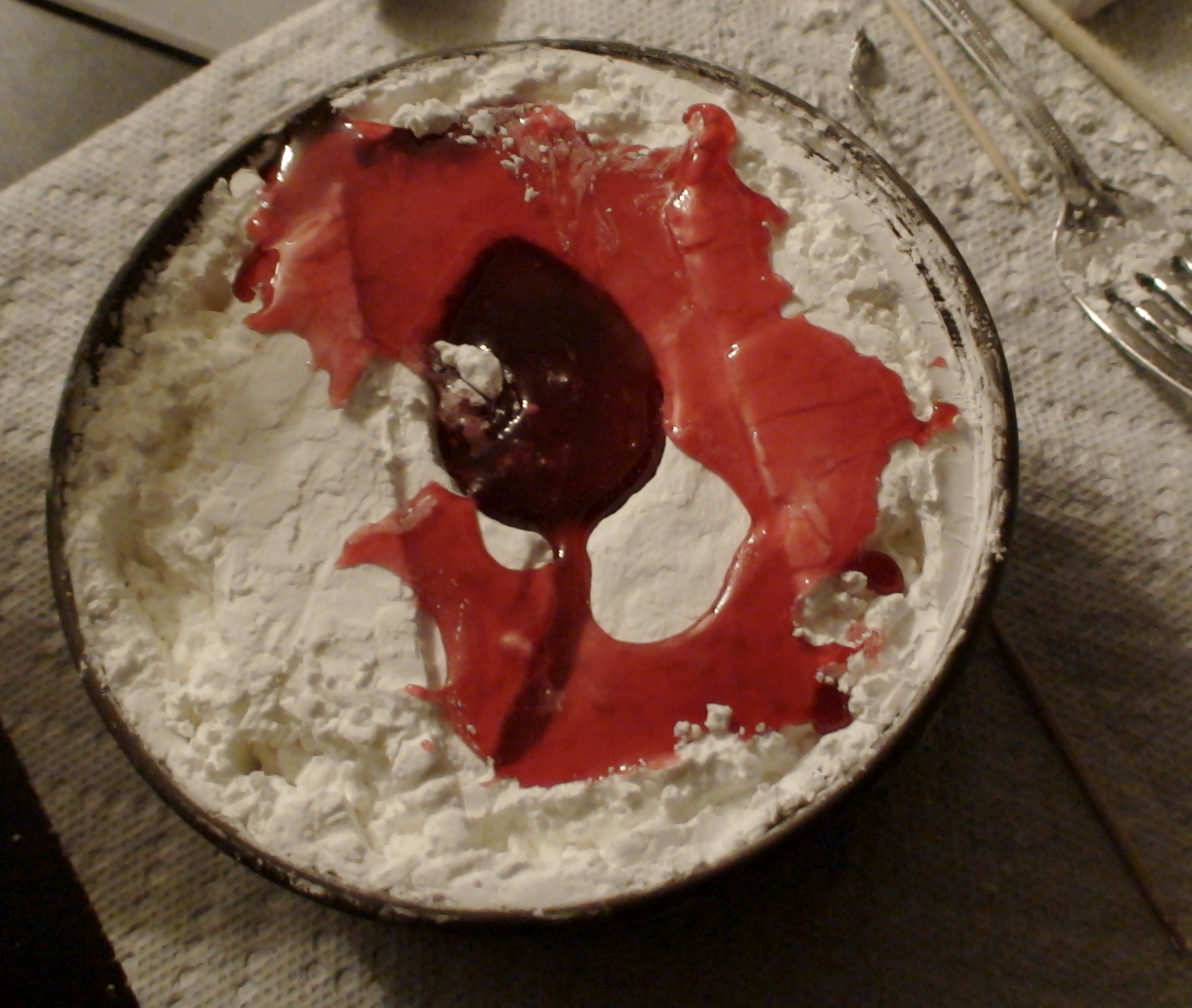
We will use corn starch as a mold. This is a very inexpensive versatile method for mold making. It can be used to mold gummies or any other viscous liquid such as sugar candy. Very little corn starch is used up in each molding and any corn starch still in the bowl after the gummy is removed can be reused indefinitely.
Select a bowl or other container that is slightly deeper than the depth of your part and fill it with with corn starch. It may be necessary to put the corn starch in the oven briefly to dry it out. You will want to sift the corn starch with a wire whisk or a fork so it is nice and fluffy.
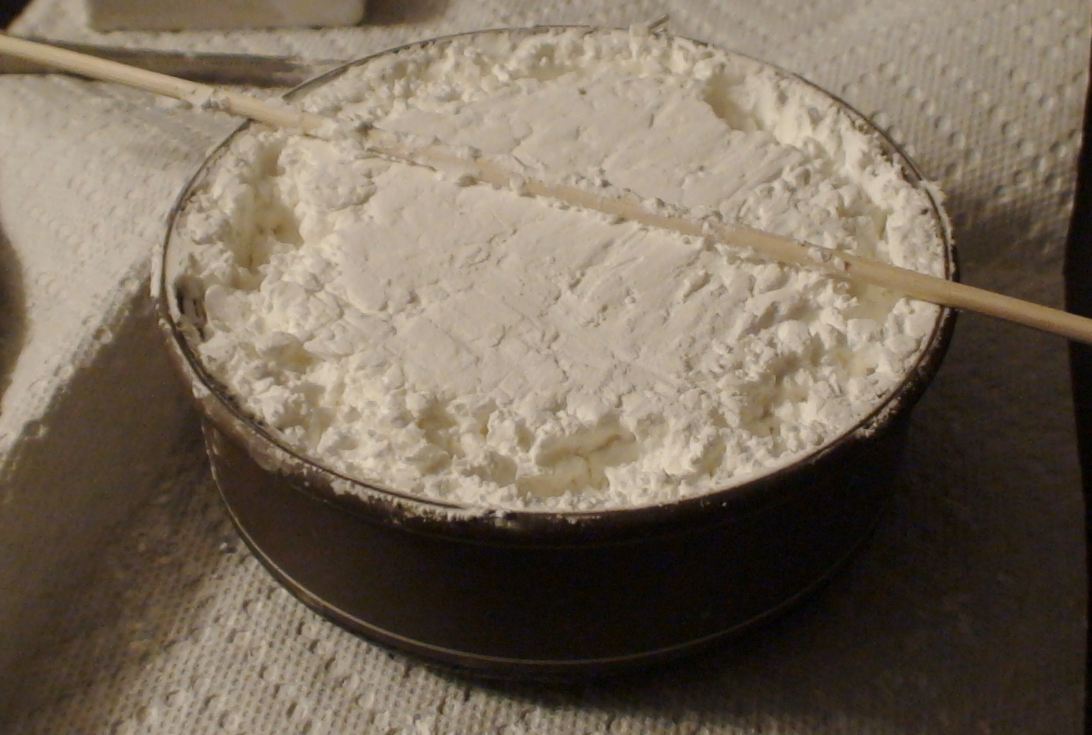
Using a knife or other straight edge (I used a kabob stick), level off the surface of the corn starch. Try not to compact the corn starch here.
Gently press the blank part into the surface of the corn starch. You want to press it in level with the top surface or slightly deeper.
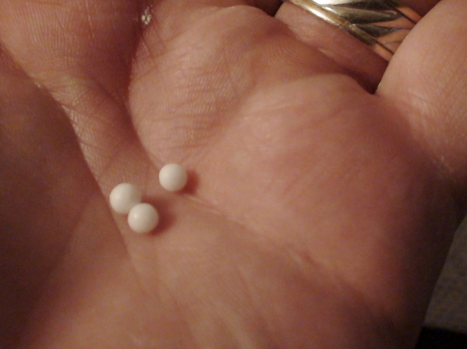
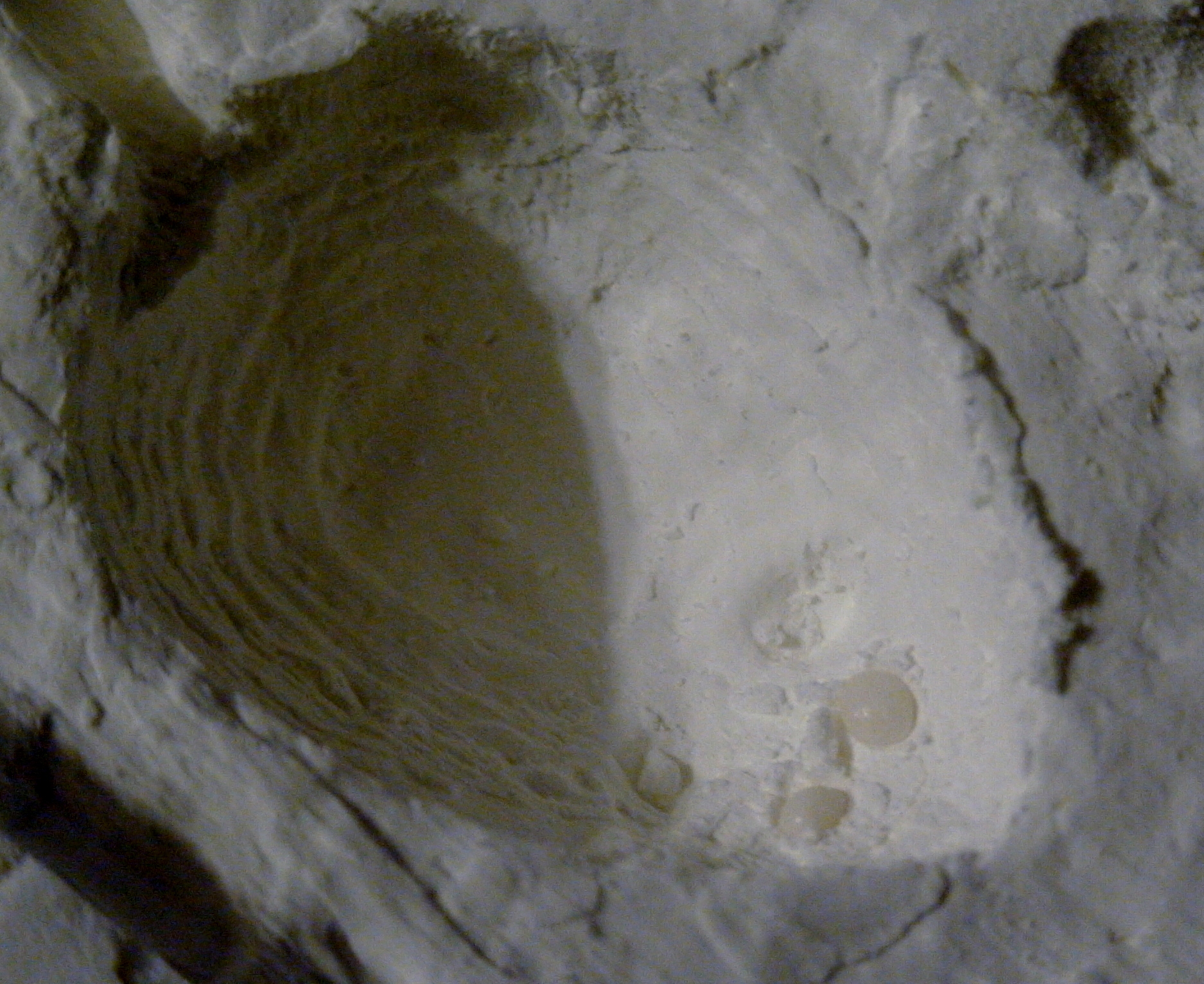
In my model I decided to use pearl nonpareils to make beady mouse eyes. Any solid extra decorations should be carefully placed into the mold at this time. I used a toothpick to form a small pocket for the eyes and pressed them into the corn starch to hold them in place.
There are many recipes for making gummies from scratch on the internet. While this is no-doubt the best way to make your gummy material, there is a shortcut. If you buy gummy candy in your favorite flavor it can be melted on the stove in a double boiler. Take care to not overheat the gummies as there is a small window between melted and burnt. For my molding I even took a step back from this and melted gummy bears in a microwave safe bowl in the microwave. This involves some delicacy as the gummies will melt in just a few seconds.
Be extremely careful working with melted gummy! It is extremely hot and extremely sticky and will release more heat as it solidifies on your arm. You can get serious burns from a spill and if you touch the melted gummy it will stick to your finger and burn. In full disclosure, I burned myself in this pour.
If you are using the stove to melt your gummies and your gummies are melted you don't have much time to act before they solidify. Have everything ready to pour before you start the stove. Once you are melted be careful and deliberate but don't delay. Once your gummies are well melted, quickly transfer the contents into the mold, filling it to the brim.
I prefer to use the microwave. This allows for a different technique as long as your mold can fit in the microwave.
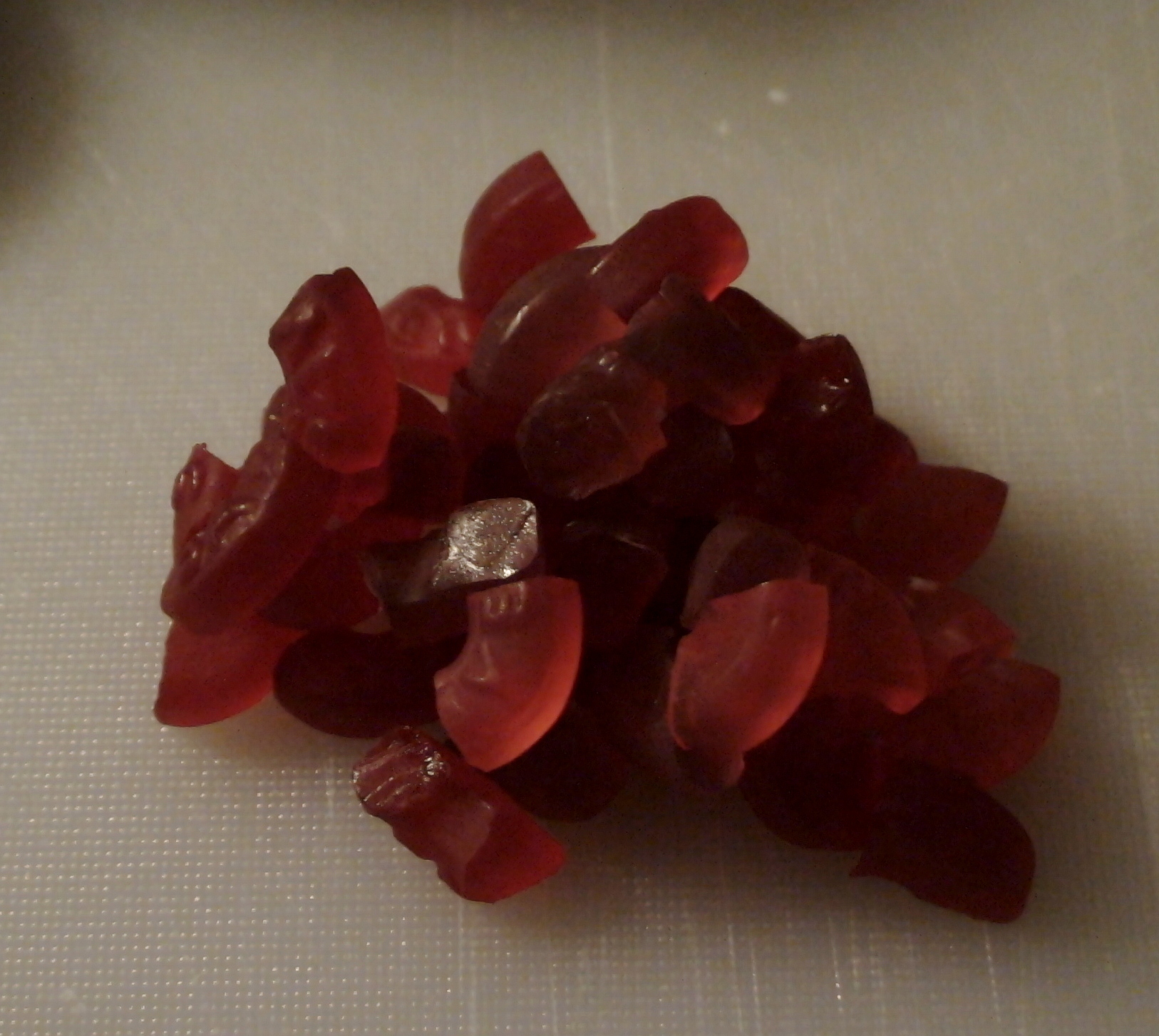
First, prepare your gummies. They can melt in easier if you chop them up a bit. If you are using a mixture of flavors, mix them up into a pile. If in doubt, use a little more than you think you need. Some of the gummy will stick to the plate and will be wasted.
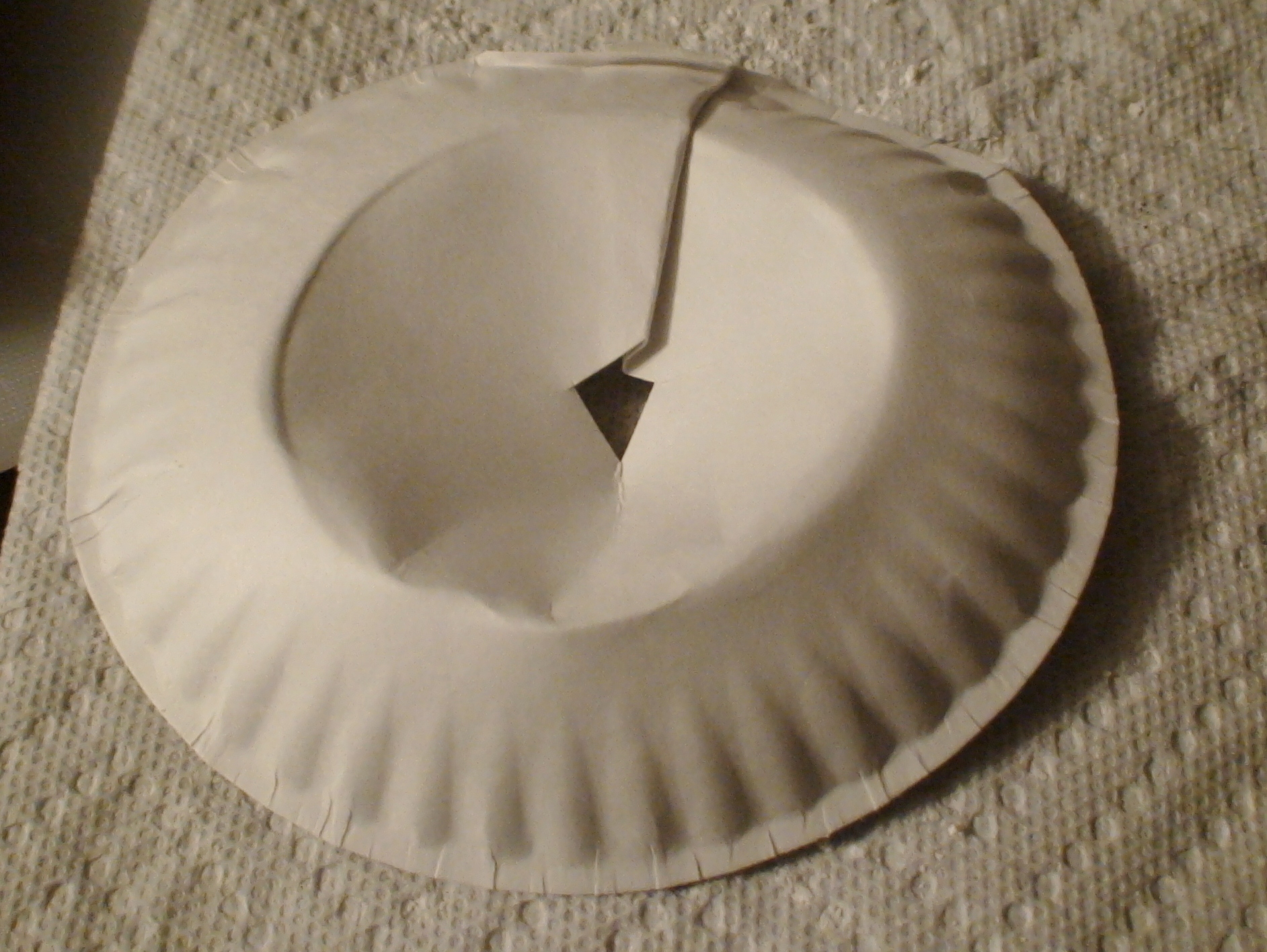
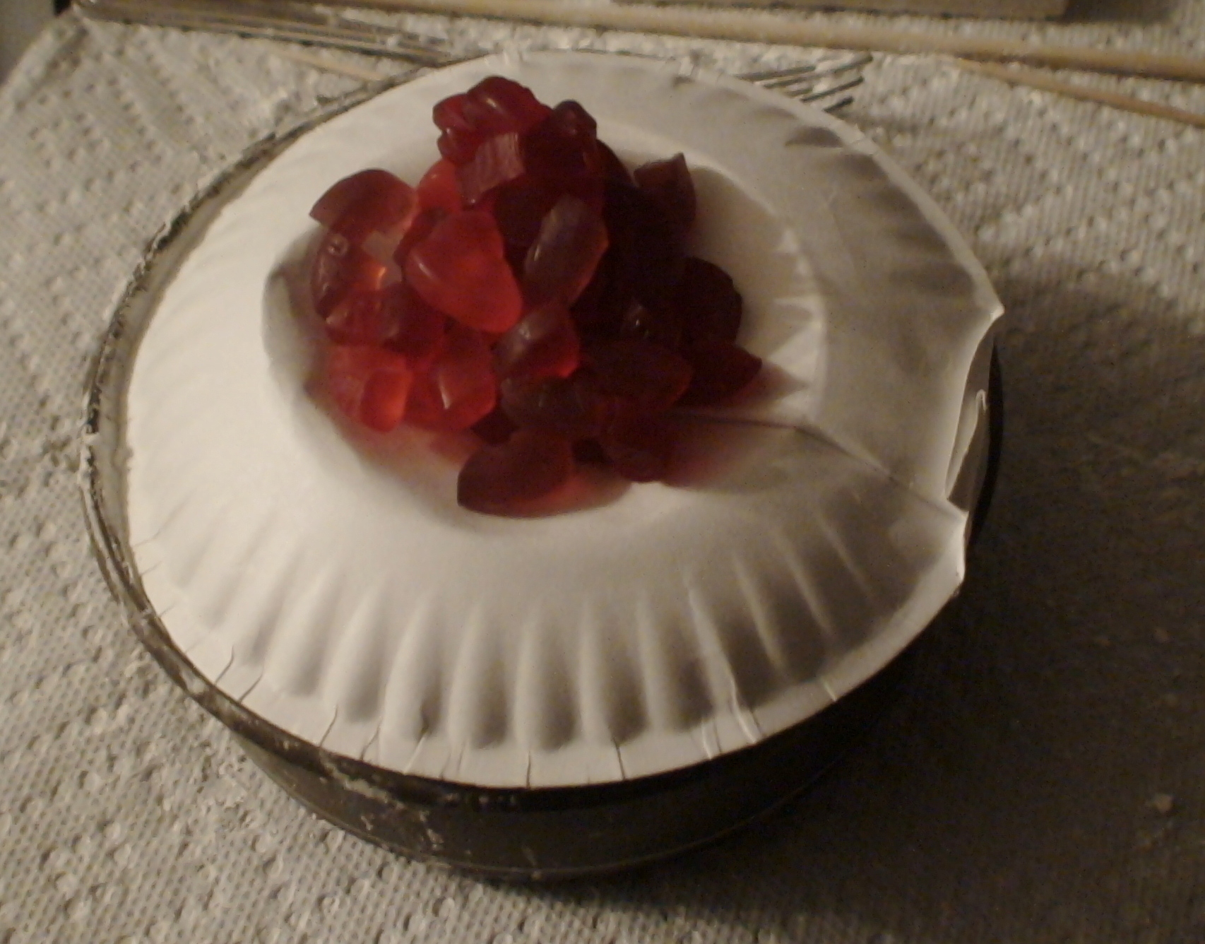
Next, take your paper plate and cut a hole in the center as shown. Fold a crease in the plate and dimple the center of the plate down to make a funnel also as shown. Make sure your plate is sized such that it can go over the mold without disturbing the mold cavity.
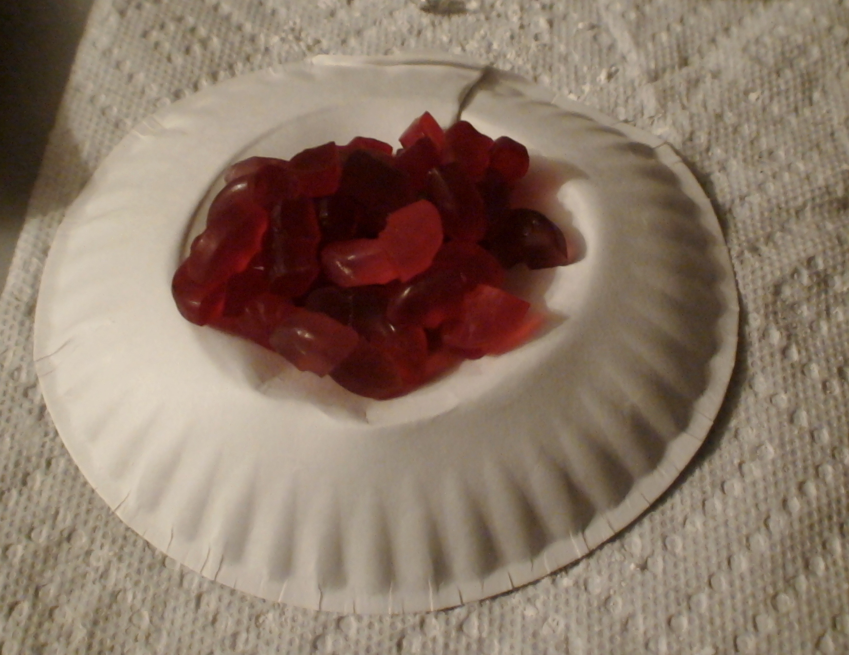
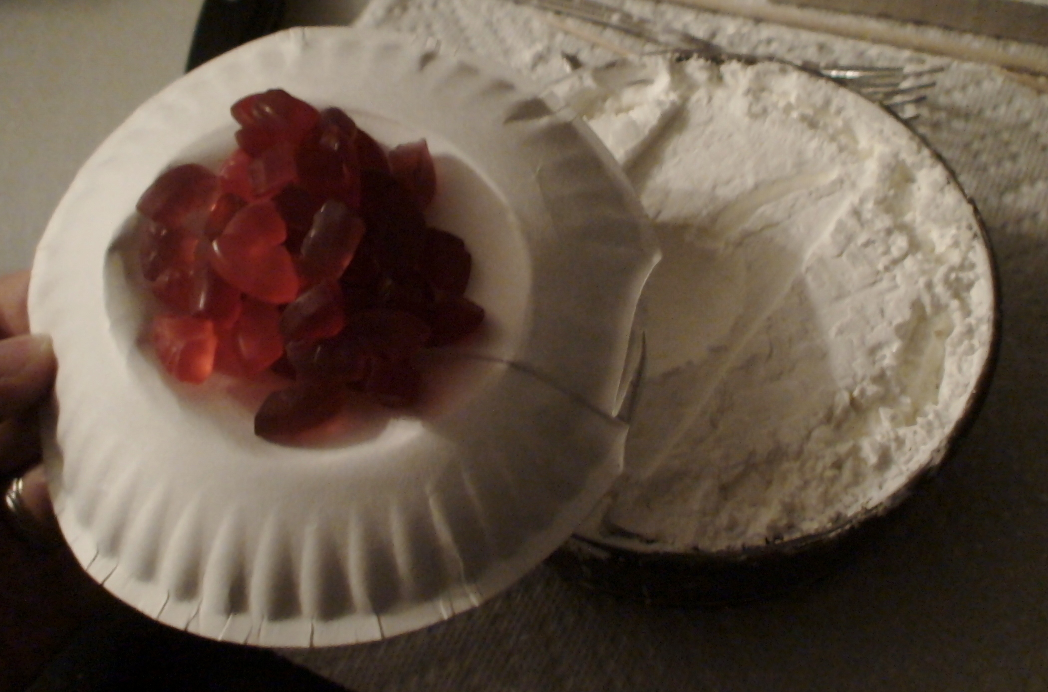
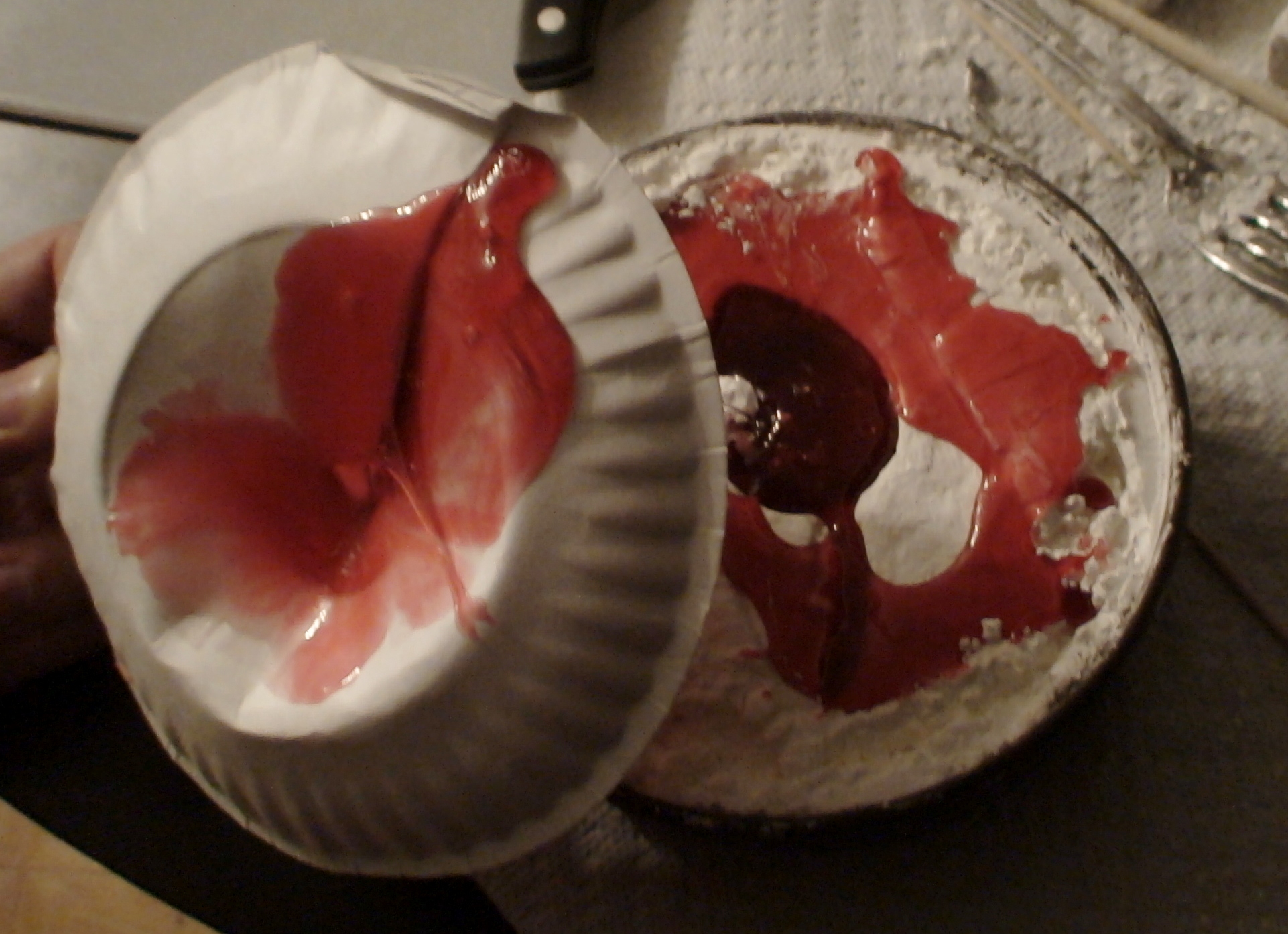
Place your gummies in the cone of the funnel and the funnel on top of the plate, centering the hole over the mold cavity. As your gummies melt they will flow down through the center of the cone and into to the mold. This way we don't have to handle the melted gummy at all. It also doesn't require any cleanup since the plate is discarded after you are done molding.
Place the mold with plate and gummies into the microwave. Heat them for 5-10 seconds at a time until the gummies fully melt and flow into the cavity. You may see a small amount of boiling but that is ok.
Remove the plate and cover the mold to keep off dust.
Once poured, don't touch! Place the molded gummy in a place where it won't be disturbed. Leave it to cool for 24 hours at room temperature. Don't put it in the refrigerator or freezer as this will toughen your gummy.
De-Molding and Final Steps
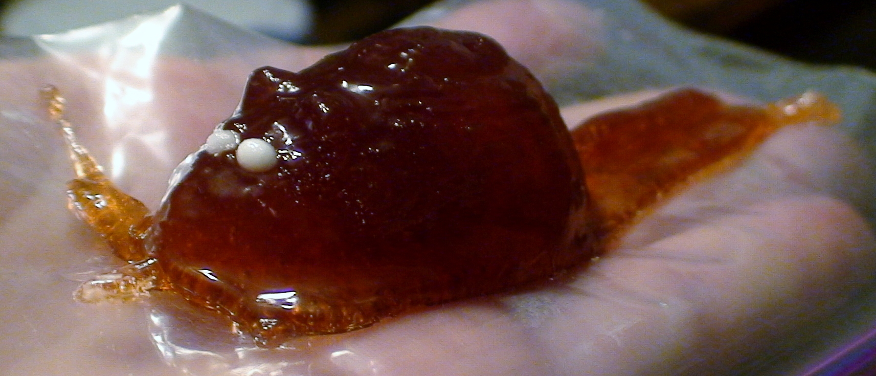

After 24 hours your gummy should be fully solidified. Simply lift the part from the mold.
If needed or desired, trim off any gummy that spilled over the mold sides. A scissors works well here.
You will notice that your gummy is covered in corn starch. This is normal. Place a small amount of food oil (olive, vegetable, canola, etc...) in a plastic bag or other container with your gummies. Shake the bag or container, which will help to knock off flash, stringers, or sharp edges. It will also remove the corn starch, and will make the gummy have a nicer surface finish.
At this point, all that is left to do is invite over friends and enjoy your gummies in good company.
Beyond the Basics

Now that you have these basic techniques down, there are several directions that you can go.
Food-safe high temperature silicone RTV mold material is available from many sources including possibly your local hobby store. This material can be used to make a semi-permanent mold. This is less messy and has less extra steps of a corn starch mold. It also can be used to cast other items. You could make water elemental ice cubes!
With a silicone mold you also have another advantage. A silicone mold is flexible and so is capable of molding parts with undercuts. The blanks for these parts will need to use more advanced carving techniques to allow for undercuts.
On the gummy side, you could try your hand at making gummies from scratch. This gives the flexibility to make custom colors and favors. These same molding techniques can be used for casting hard candy also without changes. Experiment with combining decorative inserts or multi-layered gummy pours. For gummies with a kick, soak the finished gummies in vodka or other liquor overnight to make an intoxicating confection.