Make a Concept Fighter Jet Using 123D Design
by M.C. Langer in Workshop > 3D Printing
16875 Views, 66 Favorites, 0 Comments
Make a Concept Fighter Jet Using 123D Design
.JPG)
.JPG)
.JPG)
.JPG)
.JPG)
.JPG)
.JPG)
.JPG)
.JPG)
.JPG)
.JPG)
.JPG)
.JPG)
.JPG)
.JPG)
.JPG)
.JPG)
Seven weeks ago, when I finished my first 3D printed project (the Transformers/GoBots unintentional crossover), Eric told me "Good job! Have you tried to printed it already assembled?", or something like that.
My answer was "WHAT? YOU CAN PRINT STUFF ALREADY ASSEMBLED? Wooooooooooow...".
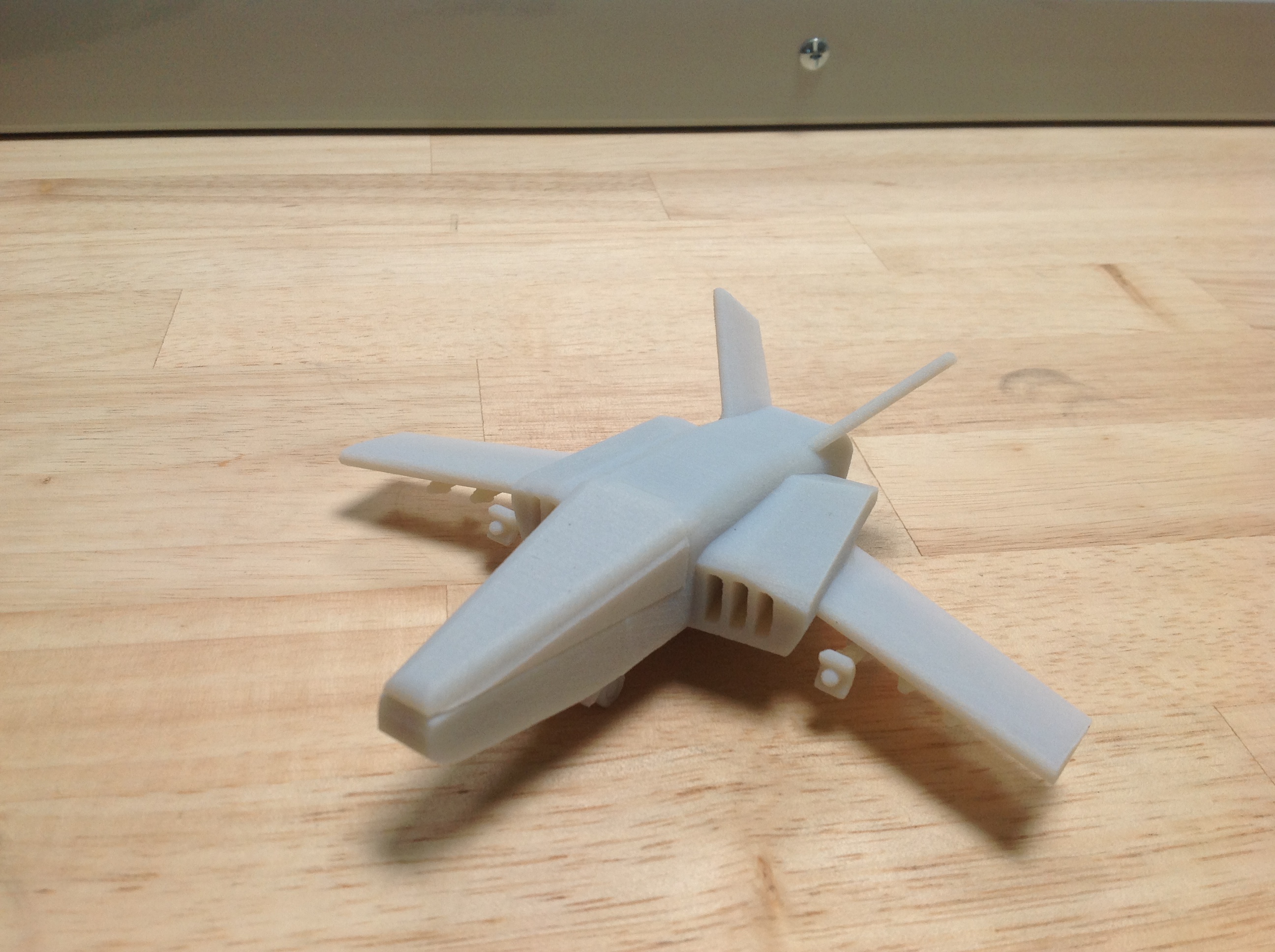
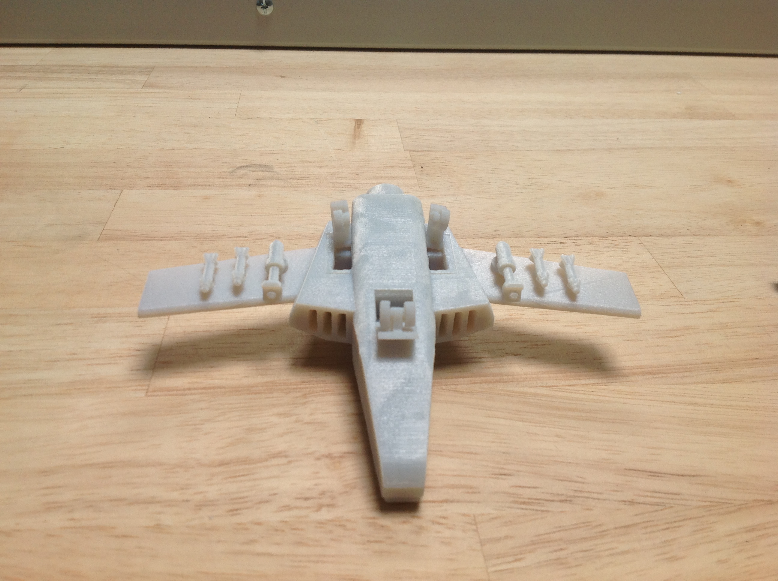
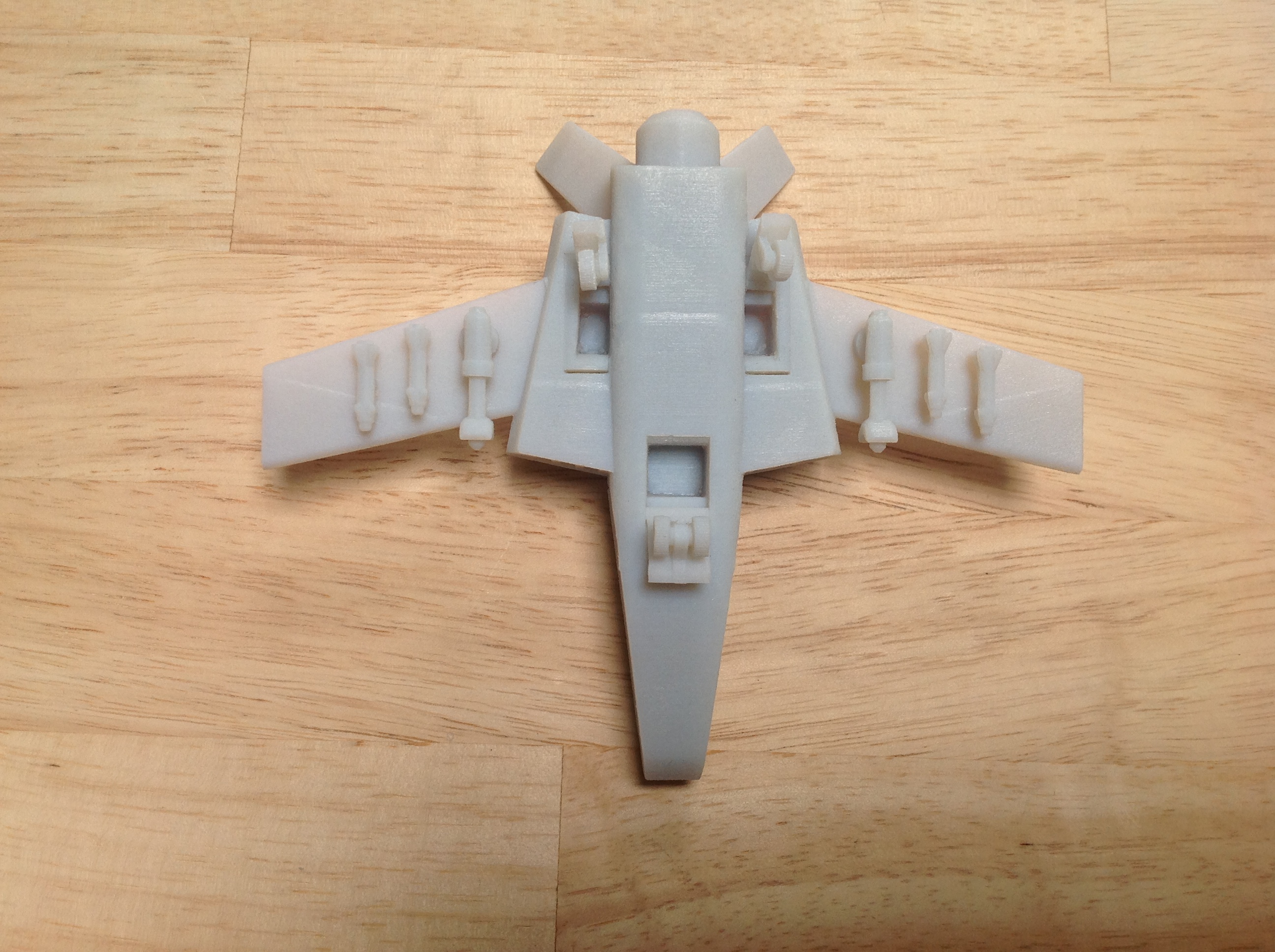
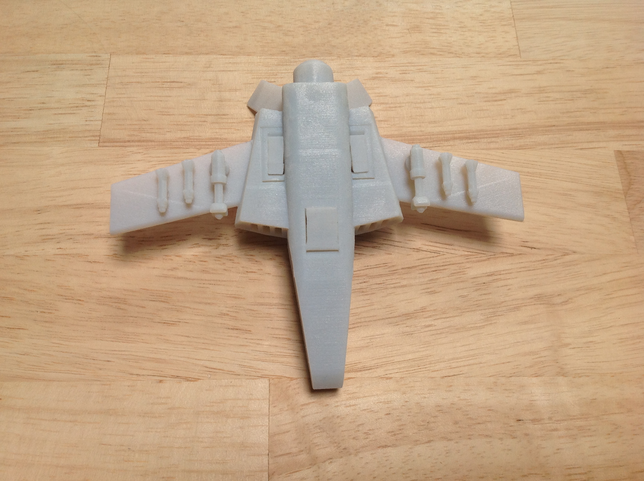
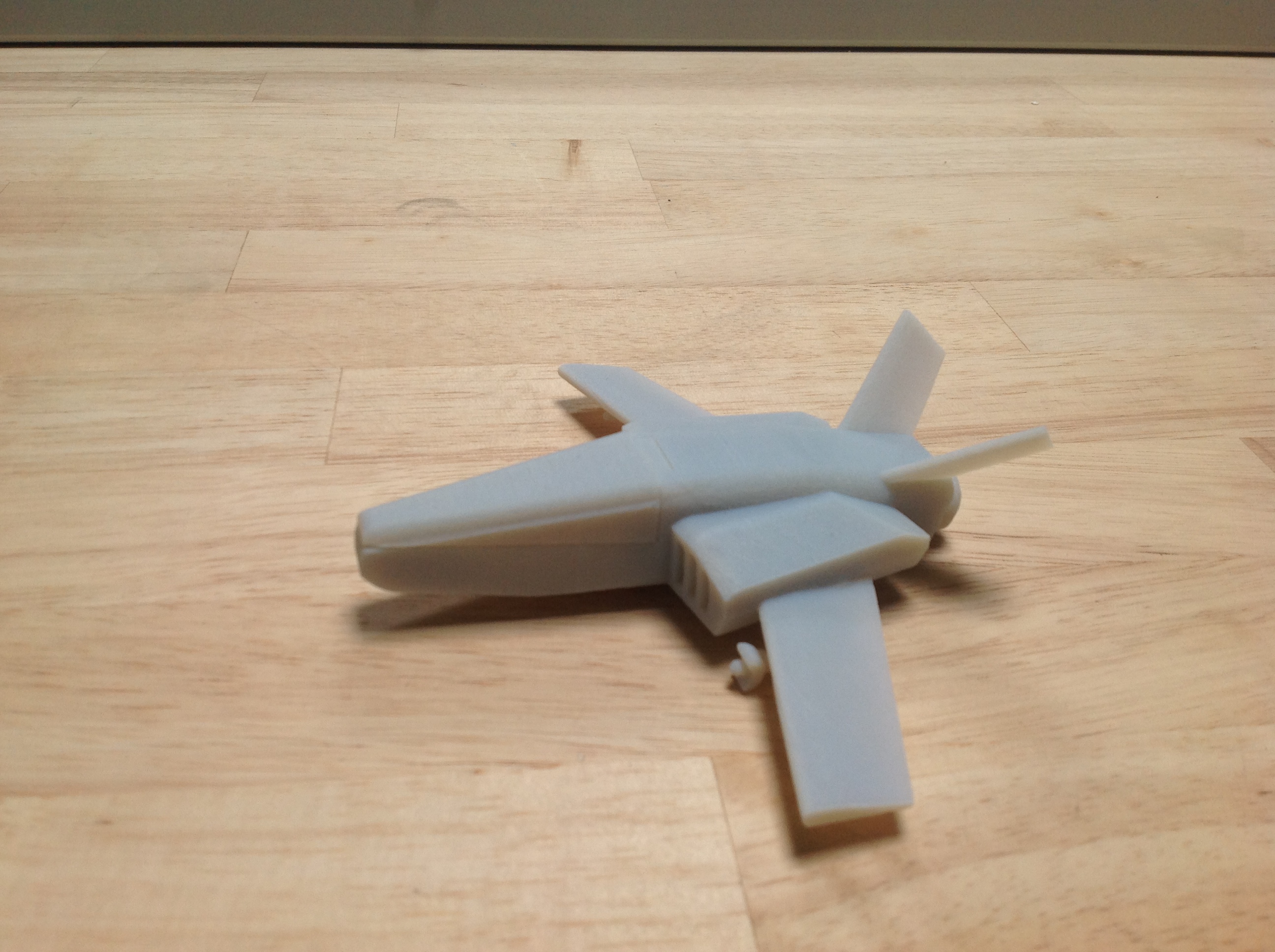
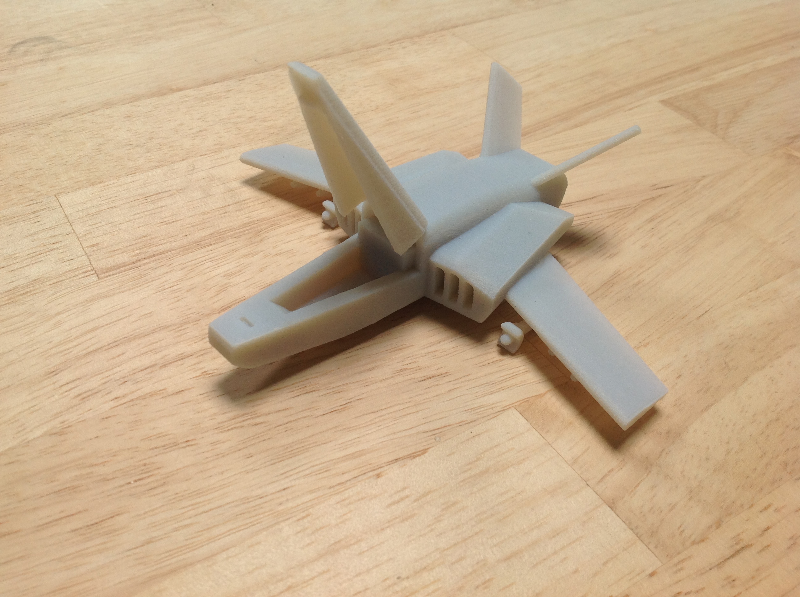
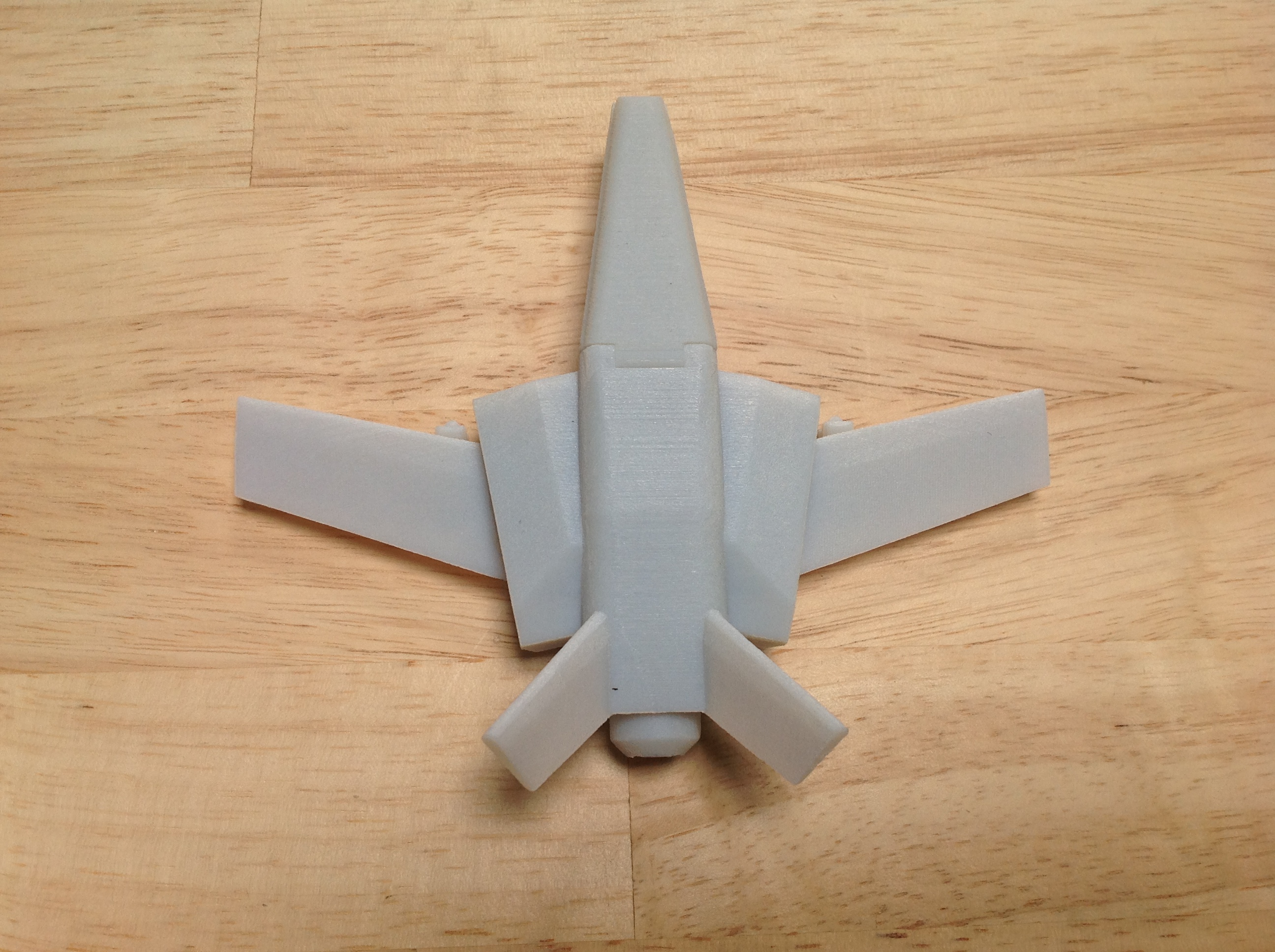
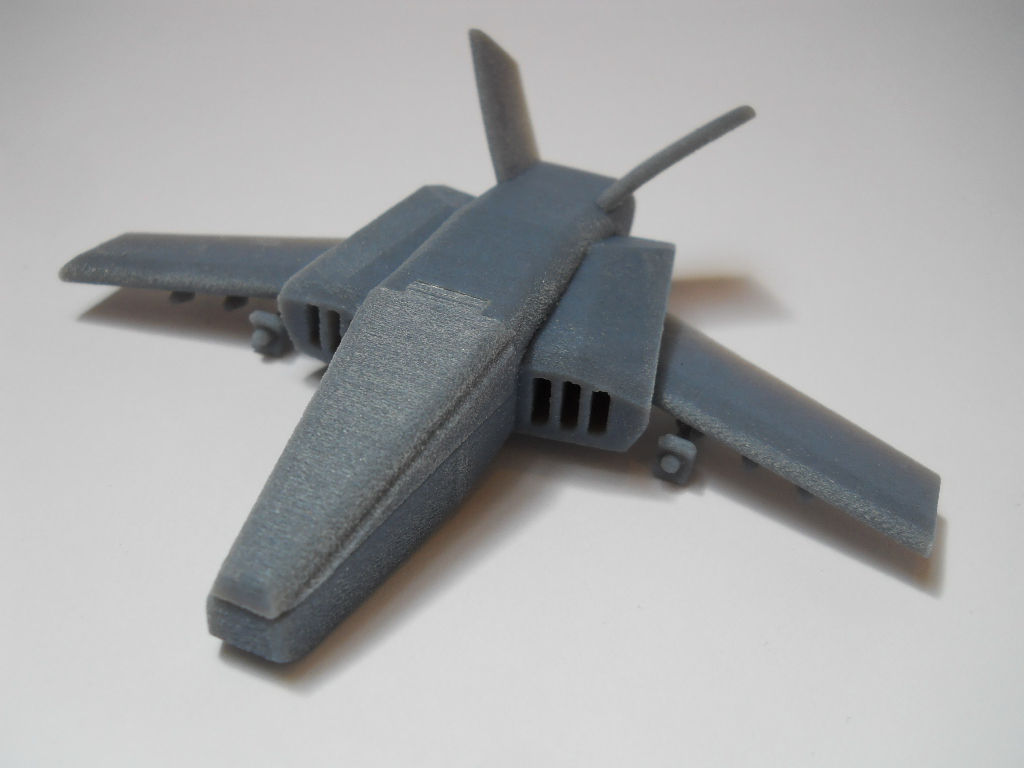
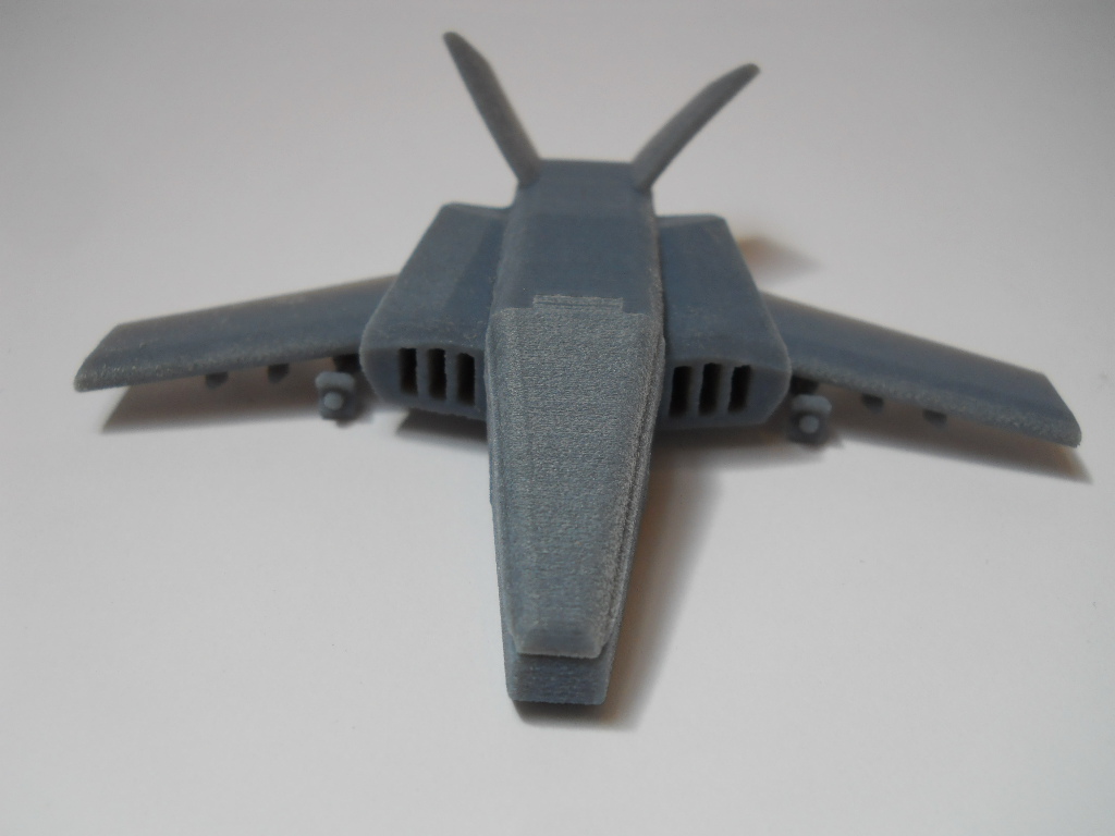
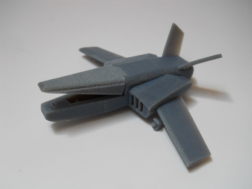
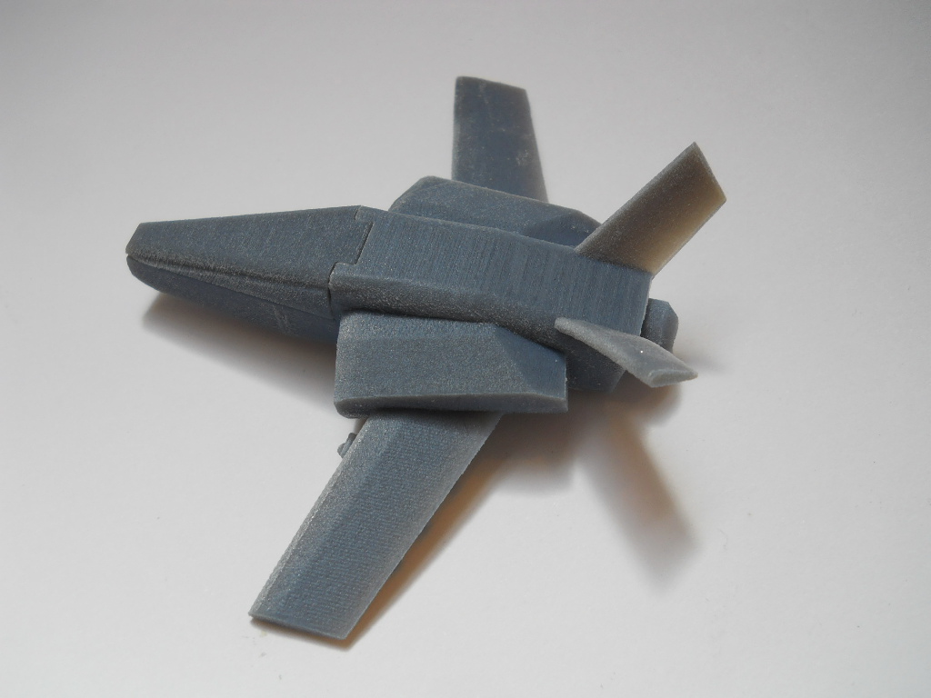
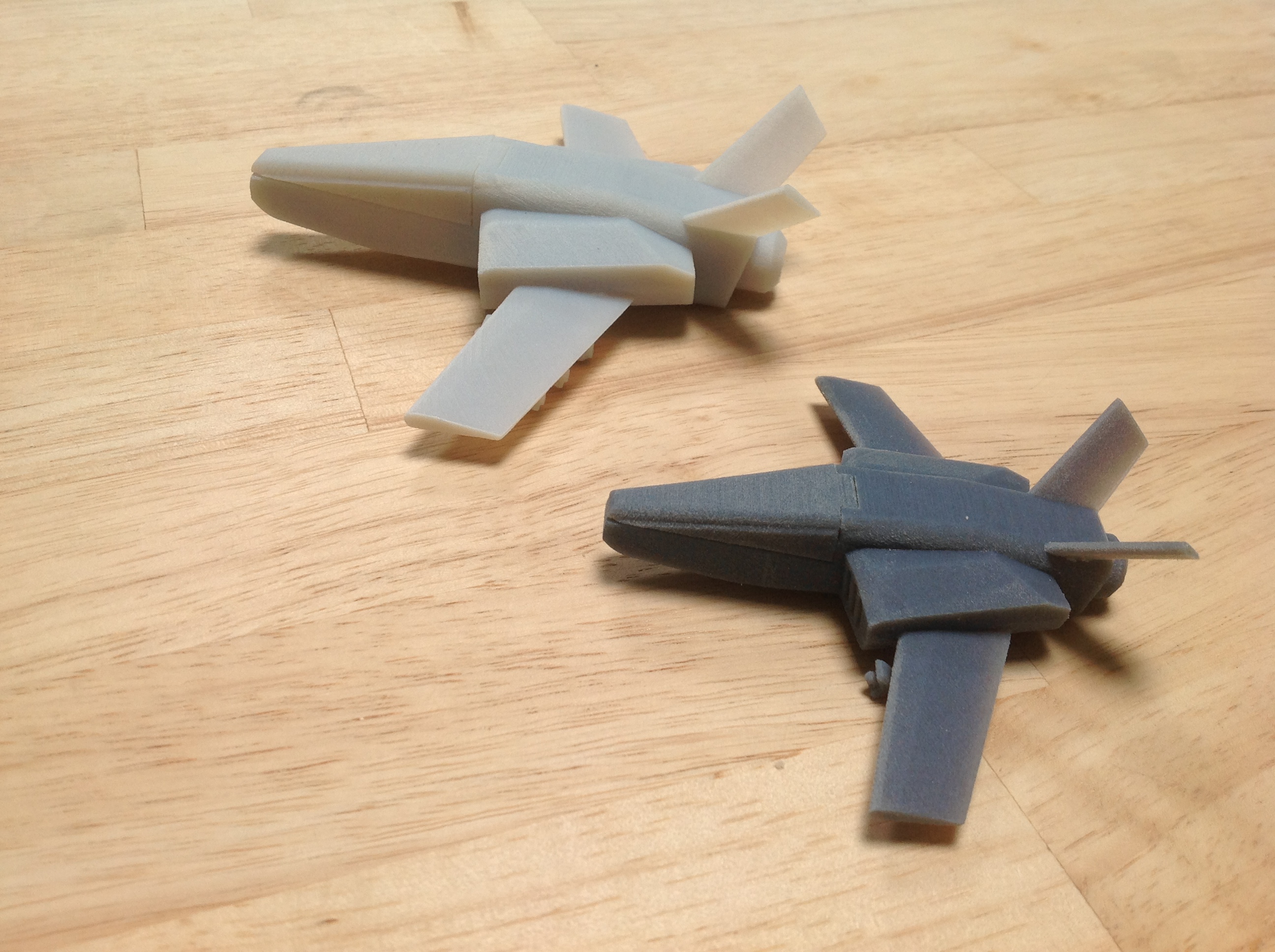
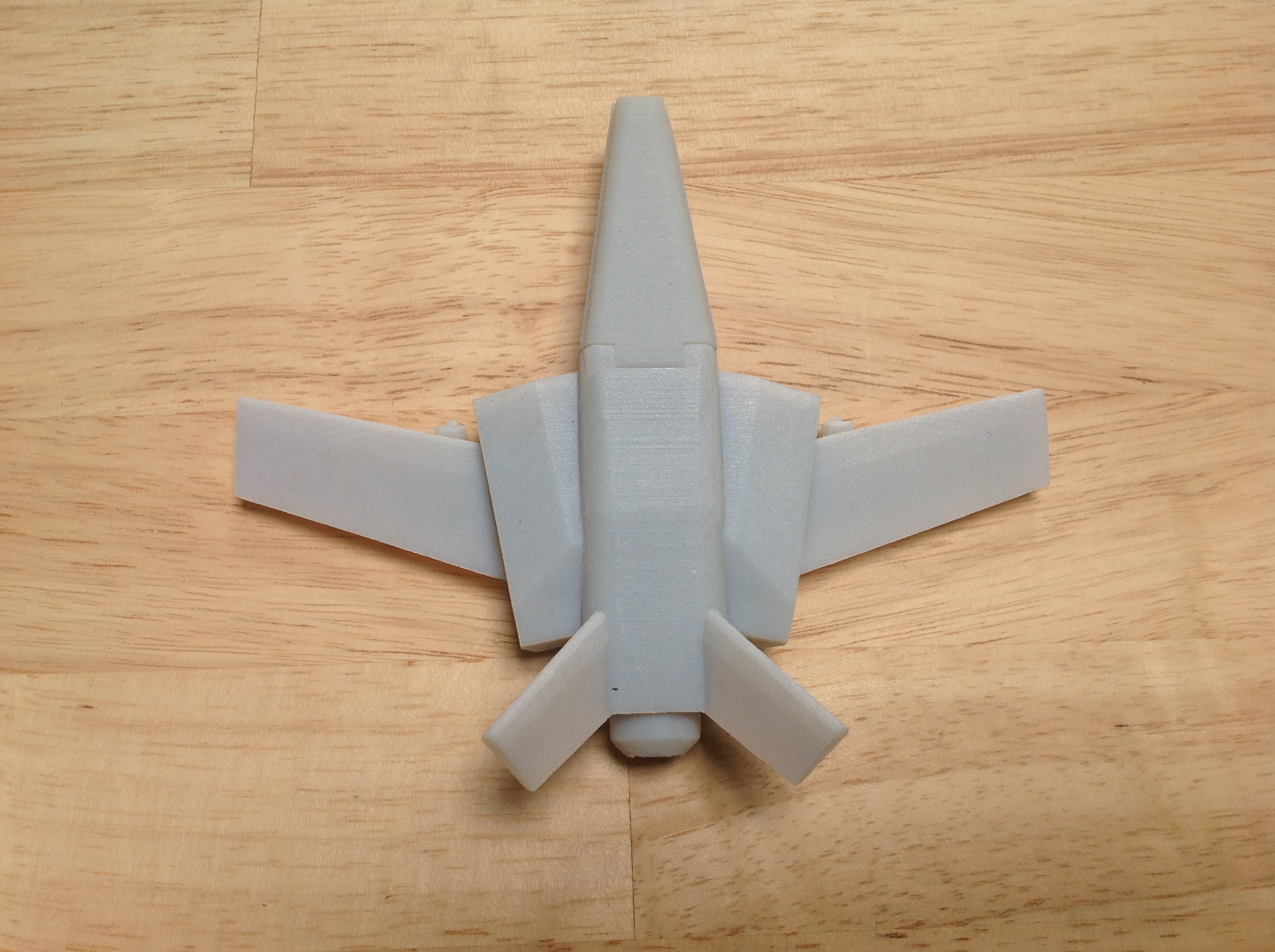
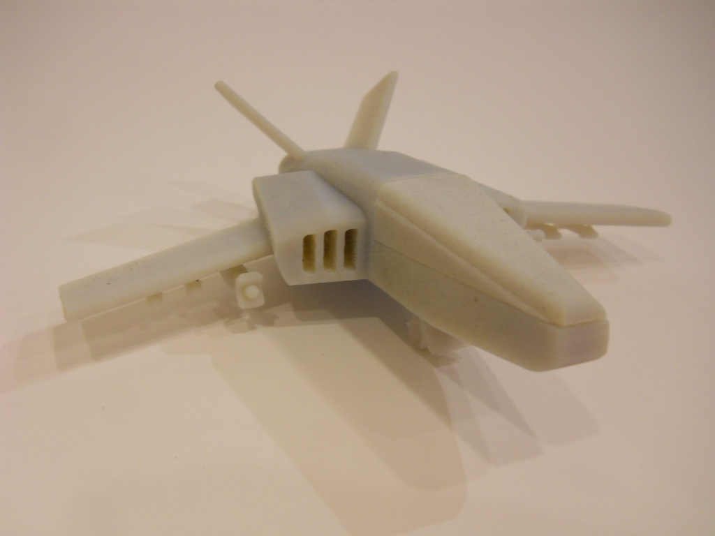
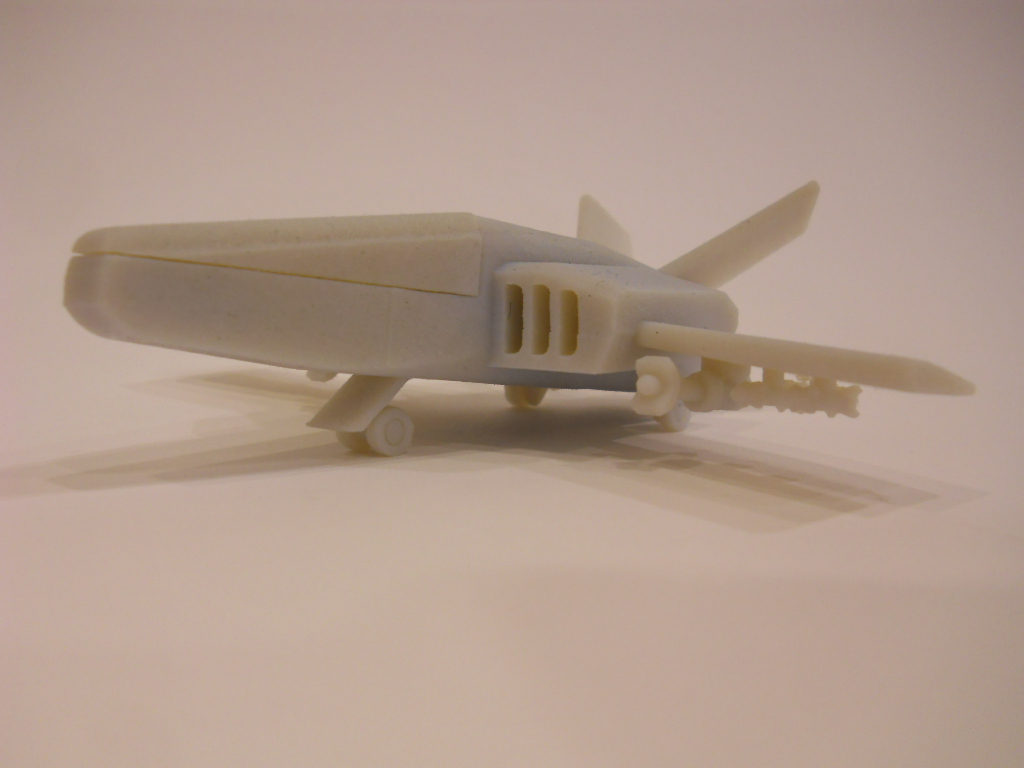
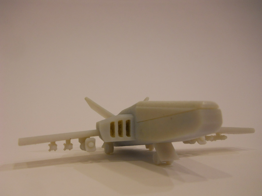
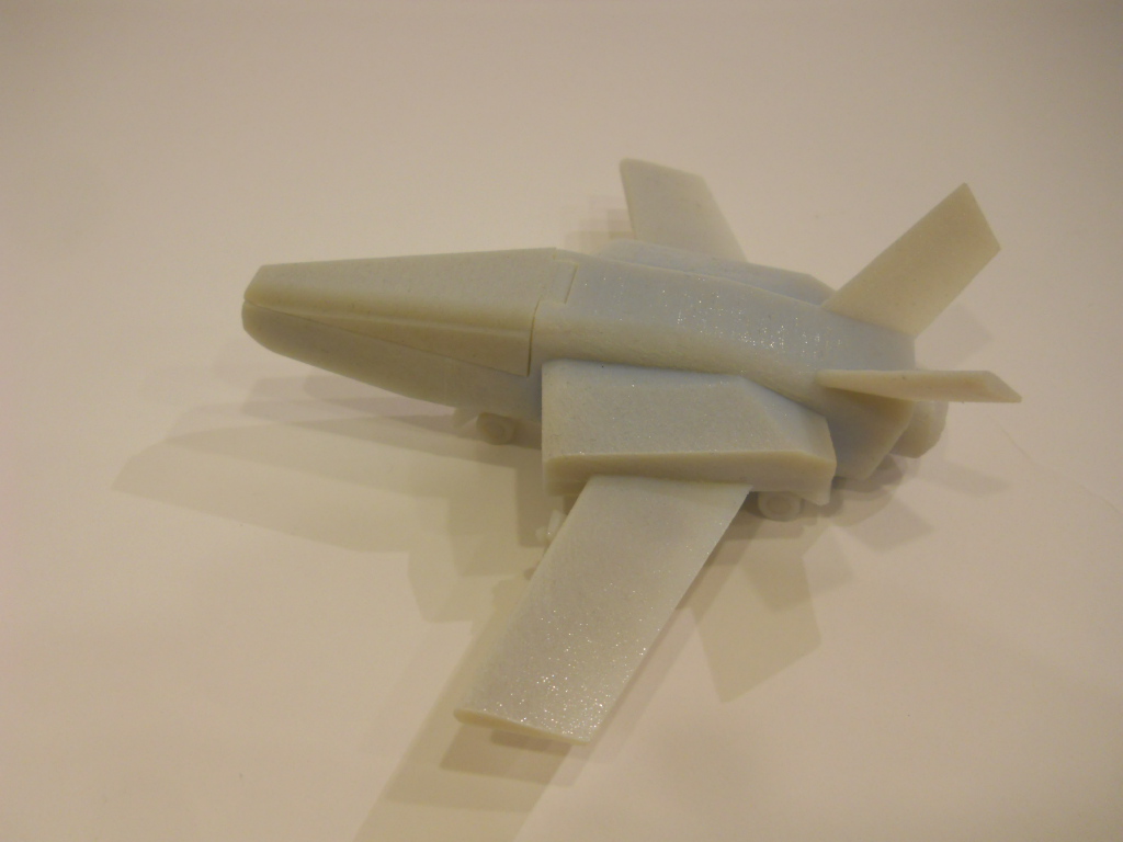
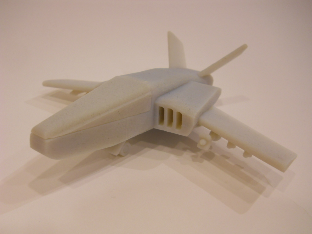
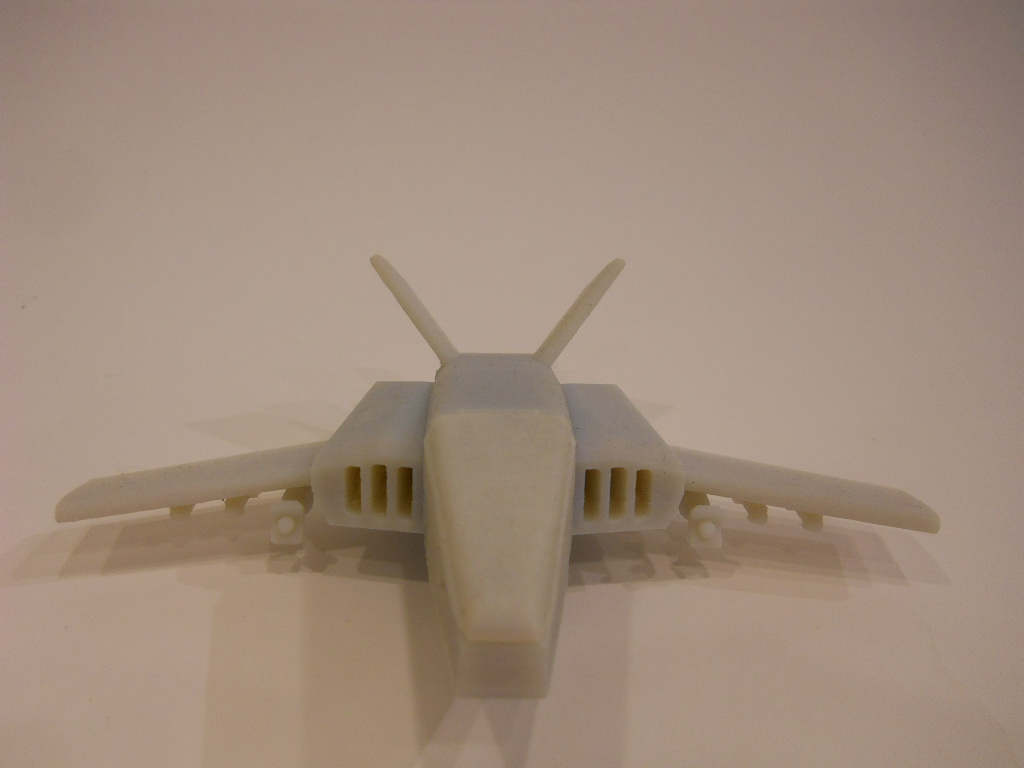
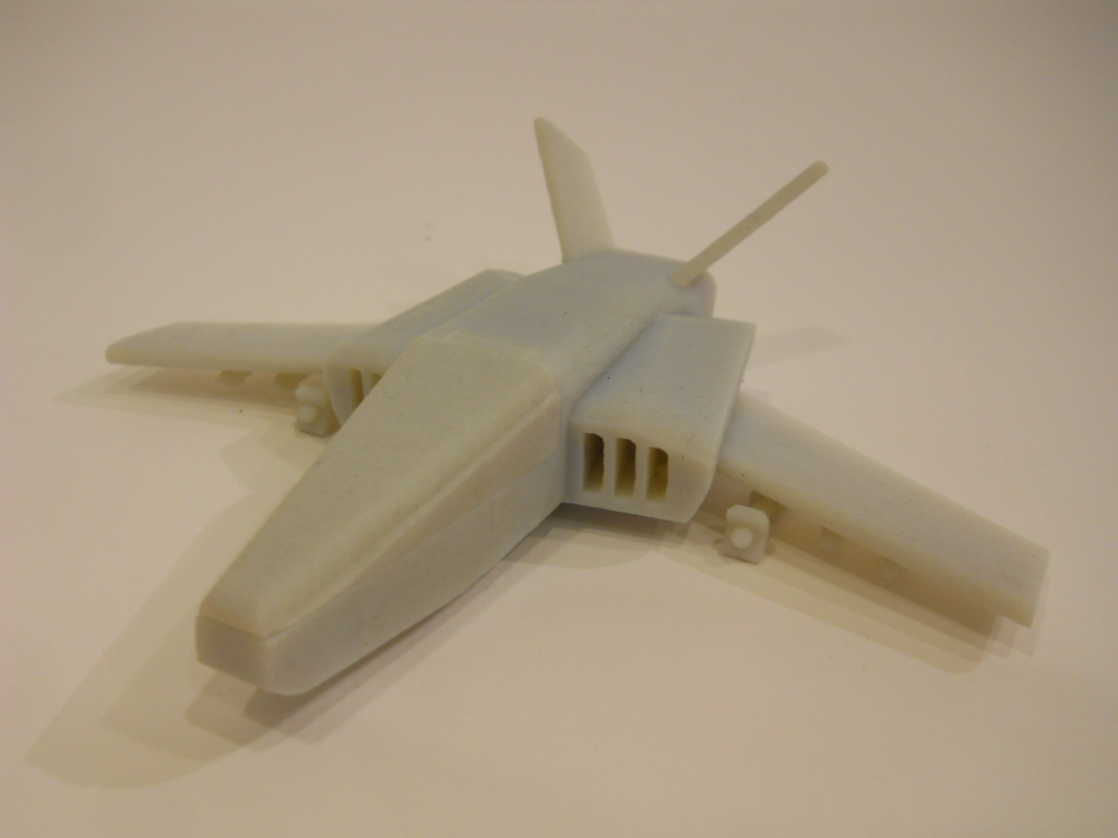
You know, I'm still a rookie in this CAD and 3D printing thing and I'm learning by myself most of the time. I'm still astonished by the unlimited possibilities in this matter. So, I decided to try making a concept jet fighter. The idea was to explore how to make a few mobile parts (in this case, the cockpit and the landing gear) already assambled to the 3D printed object. In case of failure of the mobile parts, the result had to be awesome enough for justifying the printing.
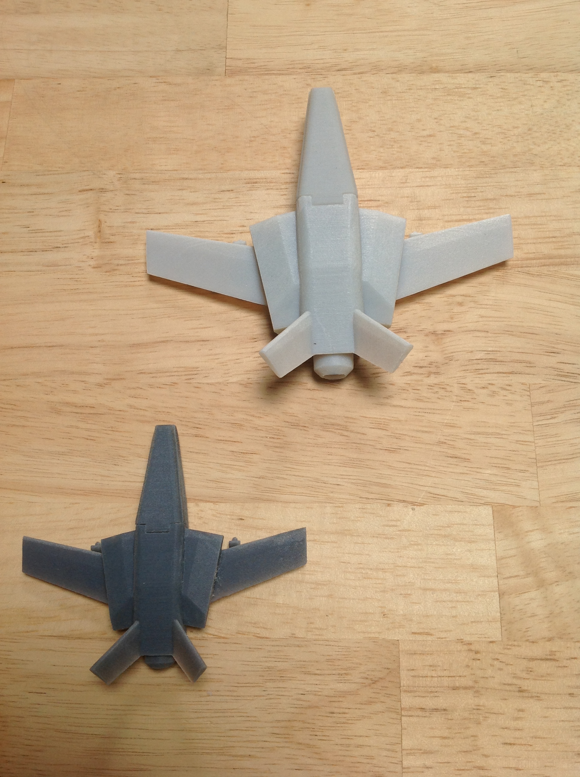
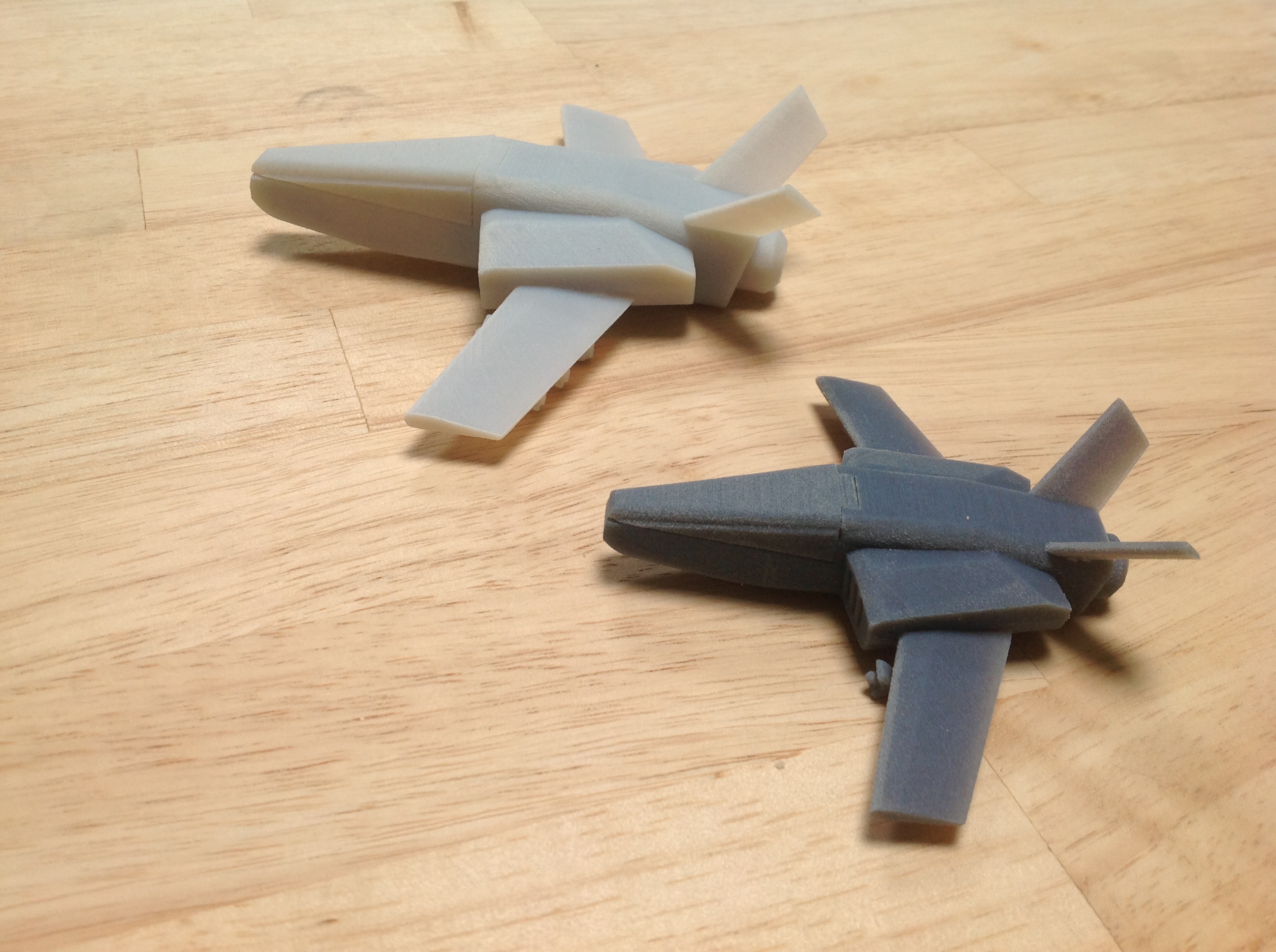
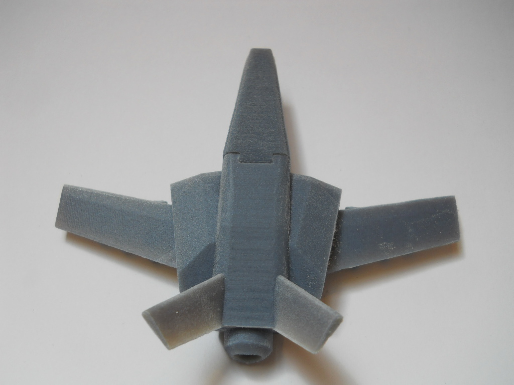
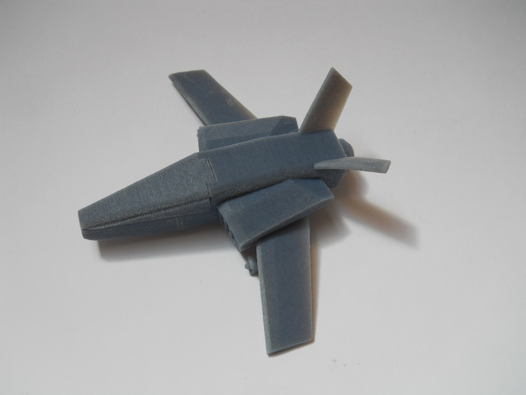
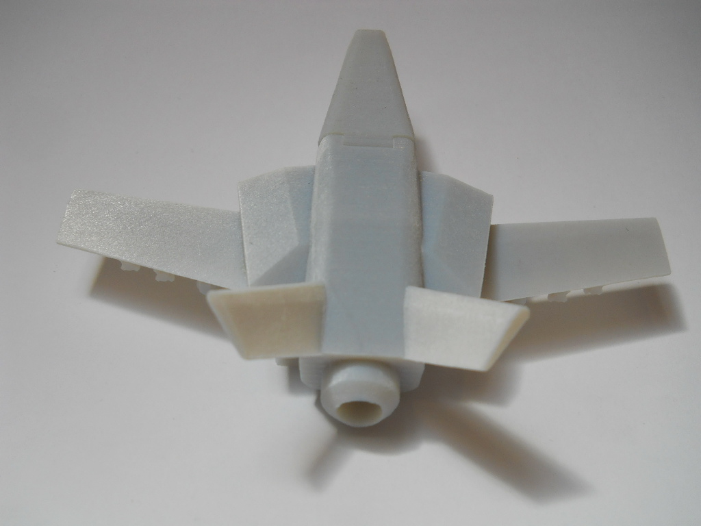
I have to be honest: the final result didn't fulfill my expectatives. I think the jet is good but not awesome. But It was a very educational experience. I learned a lot of valuable lessons:
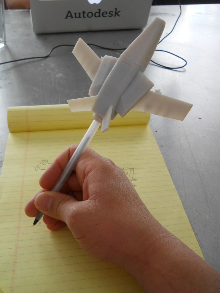
I have to admit something: at least, it's a cool pen top!
NOTES: I used the 123D Design 64bits for PC, version 1.1.41. My laptop is a Samsung with Intel Core i3-2370M 2.40GHz processor, 4,00 GB RAM and Windows 7 Home Basic. The 3D printer is an Objet.
In the design, I used the orthographic view in almost all of this instructable.
My answer was "WHAT? YOU CAN PRINT STUFF ALREADY ASSEMBLED? Wooooooooooow...".
You know, I'm still a rookie in this CAD and 3D printing thing and I'm learning by myself most of the time. I'm still astonished by the unlimited possibilities in this matter. So, I decided to try making a concept jet fighter. The idea was to explore how to make a few mobile parts (in this case, the cockpit and the landing gear) already assambled to the 3D printed object. In case of failure of the mobile parts, the result had to be awesome enough for justifying the printing.
I have to be honest: the final result didn't fulfill my expectatives. I think the jet is good but not awesome. But It was a very educational experience. I learned a lot of valuable lessons:
- Mirror pattern: Draw a line. Make half of the jet in one side of the line. Go to "Pattern", then click on "Mirror". Select the half you made and then select the line. Now, you have an entire jet. It's easy. If I had known this when I made the Transformer, I had ended it in half of the time, with more details and less "goboteness". (NOTE: In some pictures of this instructable you will see I'm working in one half, then I switch to the entire jet, then I switch back again to the half view, just for checking how it's working)
- Axles size: Be careful when you design the mobile parts. The axles have to be thick enough for resist the movement without breaking, regardless of the scale of your project when you print it. I made this jet thinking in accommodate one action figure, but I had to print it in a smaller scale. The back landing gear didn't resist so well after the fifth handling.
- Invisible jet: I found an interesting trick when I was installing the landing gear into the jet: If you want to see through the airplane for verifying the right position of the axle and you don't want to use "Materials & Outlines" in your Navigation Bar, go to "Material" in the Main Toolbar and turn the jet into glass (something like Wonder Woman's Invisible Jet).
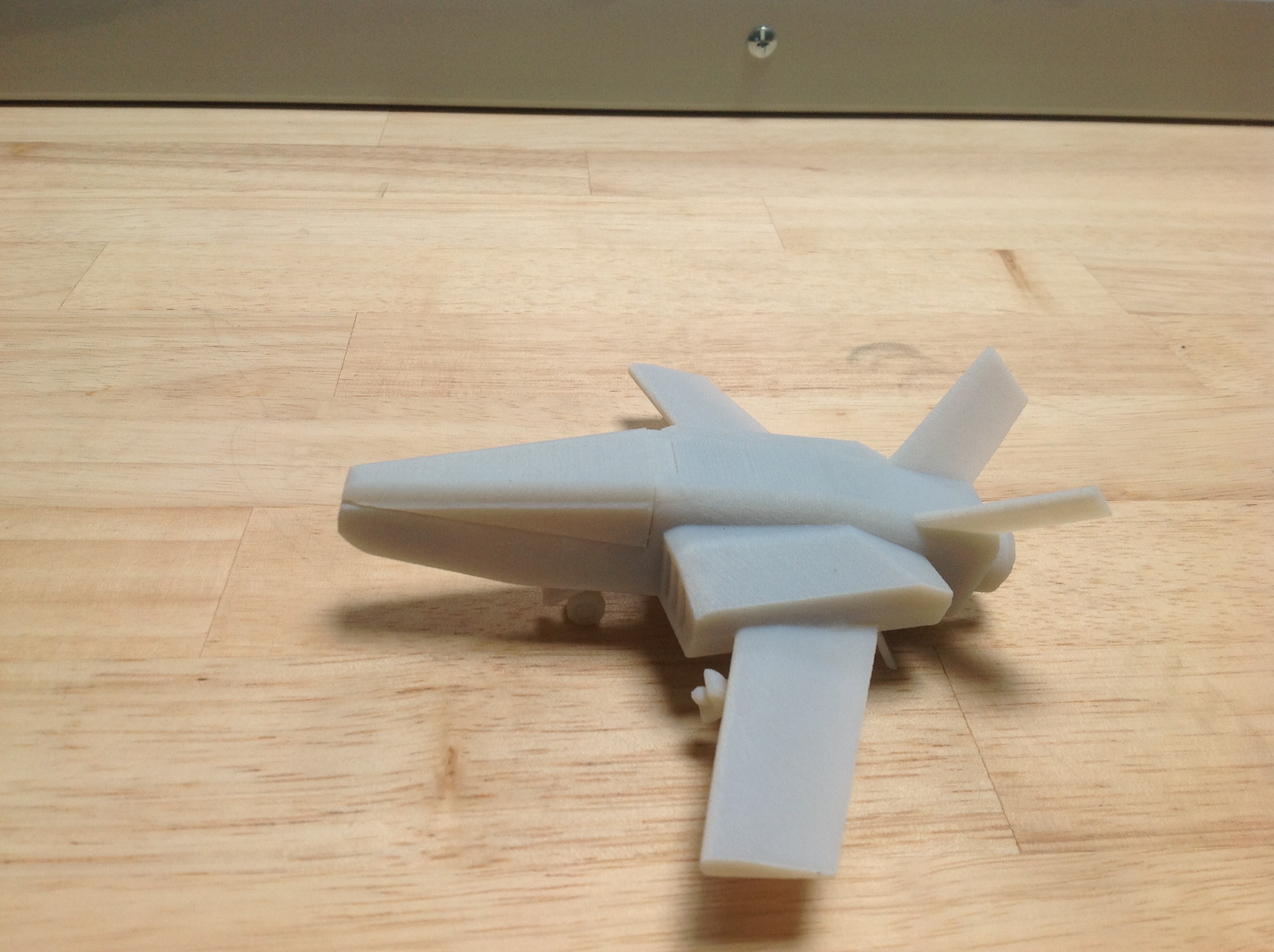
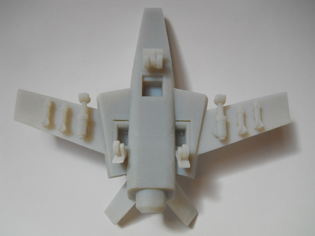
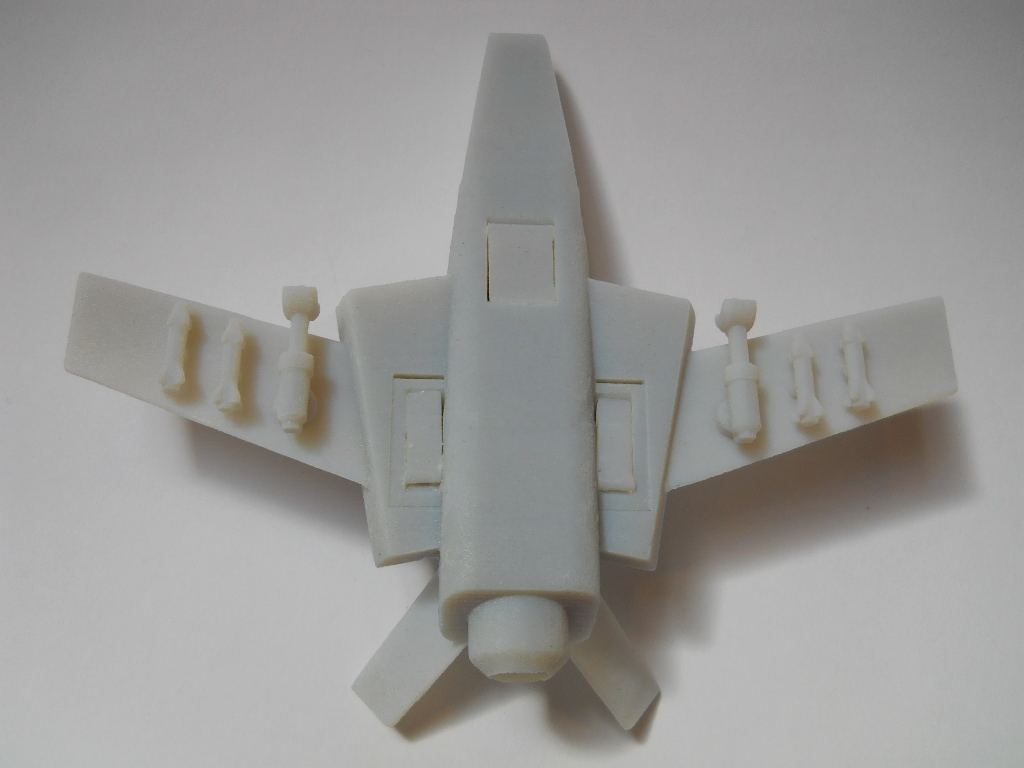
- Printing: When you print something with deployable parts (like the cockpit and the landing gear), the best is printing those parts wide open, for a better cleaning of the support material and for avoiding fusion between the mobile part and the jet. I had to print this jet with the cockpit open and somebody in the lab said "What did you print? Some kind of flying alligator?". (Supposedly it was a joke, but I like the name. So, my first 3D printed jet, I name you... "FLYING ALLIGATOR"!)
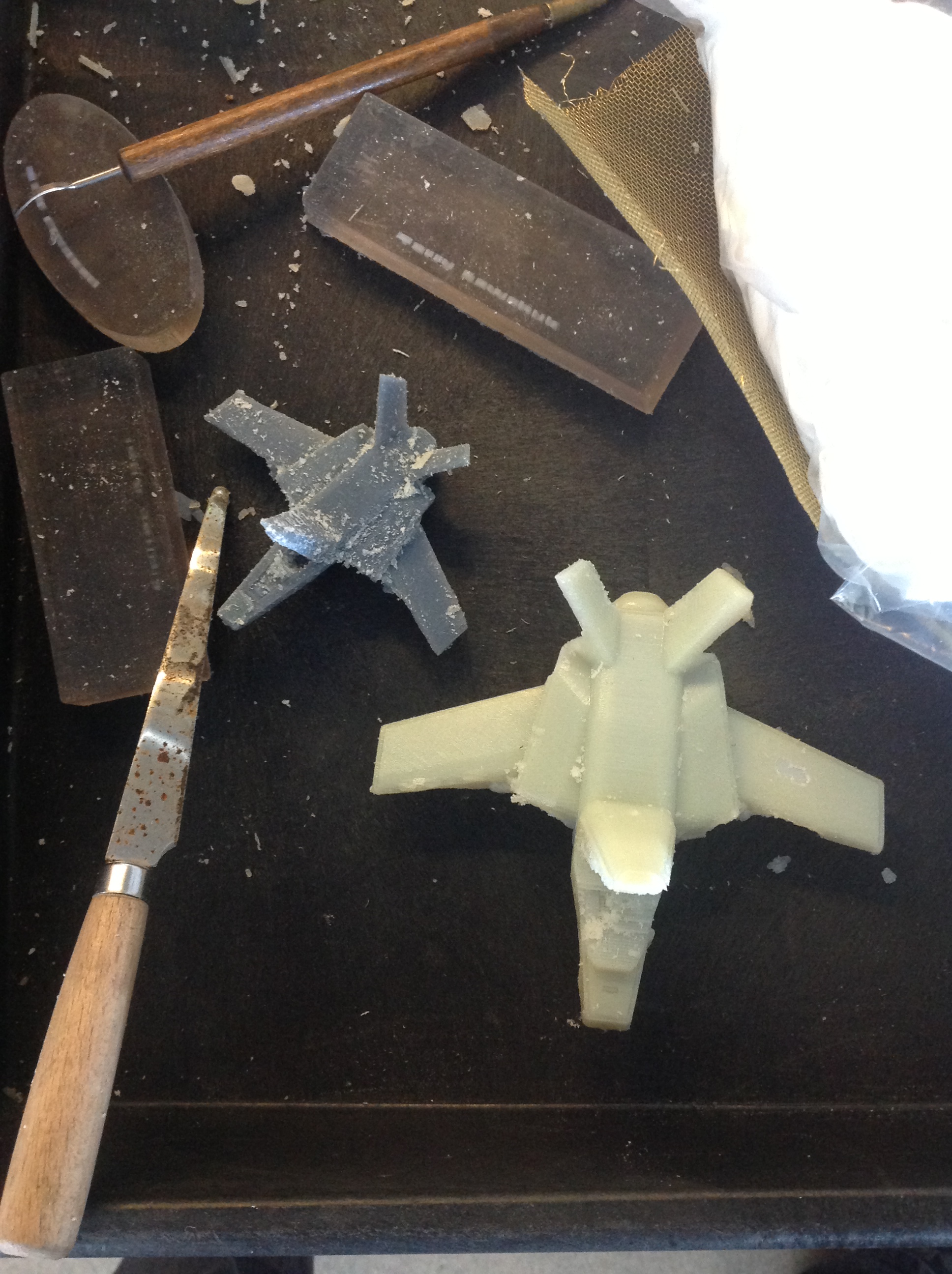
- Cleaning: I made this project on an Object 3D printer. So, I had to remove the support material using a waterjet. Be absolutelly careful, because a water stream in the wrong part can destroy parts of your project, or worst, all of it. I worked half an hour designed the helm inside the cockpit and it was blown away in seconds on the waterjet. Next time, I will design the helm aside and leave the hole in the board, clean separately and then assemble at the end.
I have to admit something: at least, it's a cool pen top!
NOTES: I used the 123D Design 64bits for PC, version 1.1.41. My laptop is a Samsung with Intel Core i3-2370M 2.40GHz processor, 4,00 GB RAM and Windows 7 Home Basic. The 3D printer is an Objet.
In the design, I used the orthographic view in almost all of this instructable.
Starting From Basics
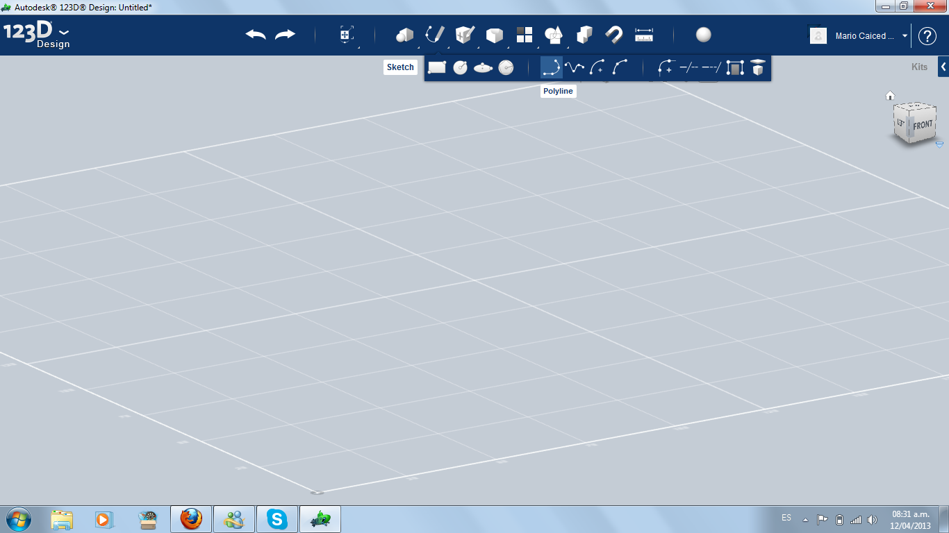
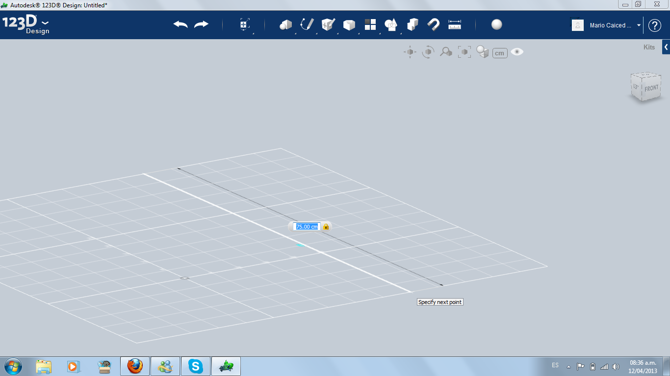
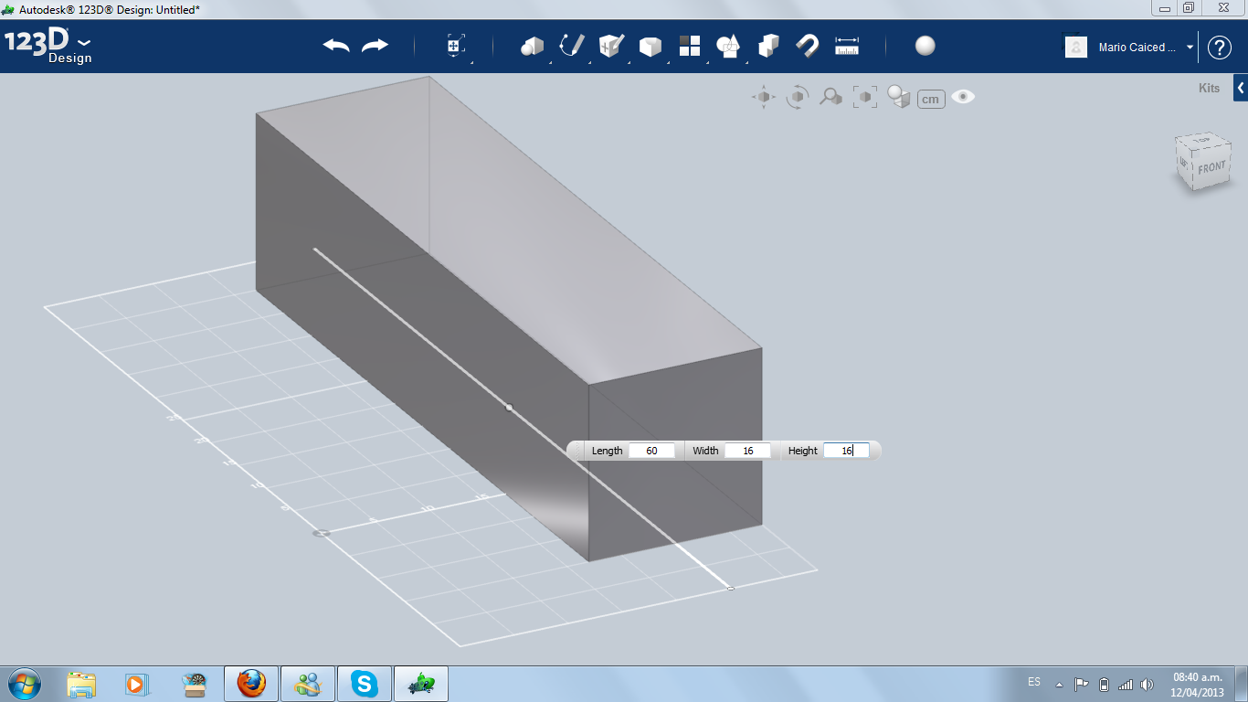
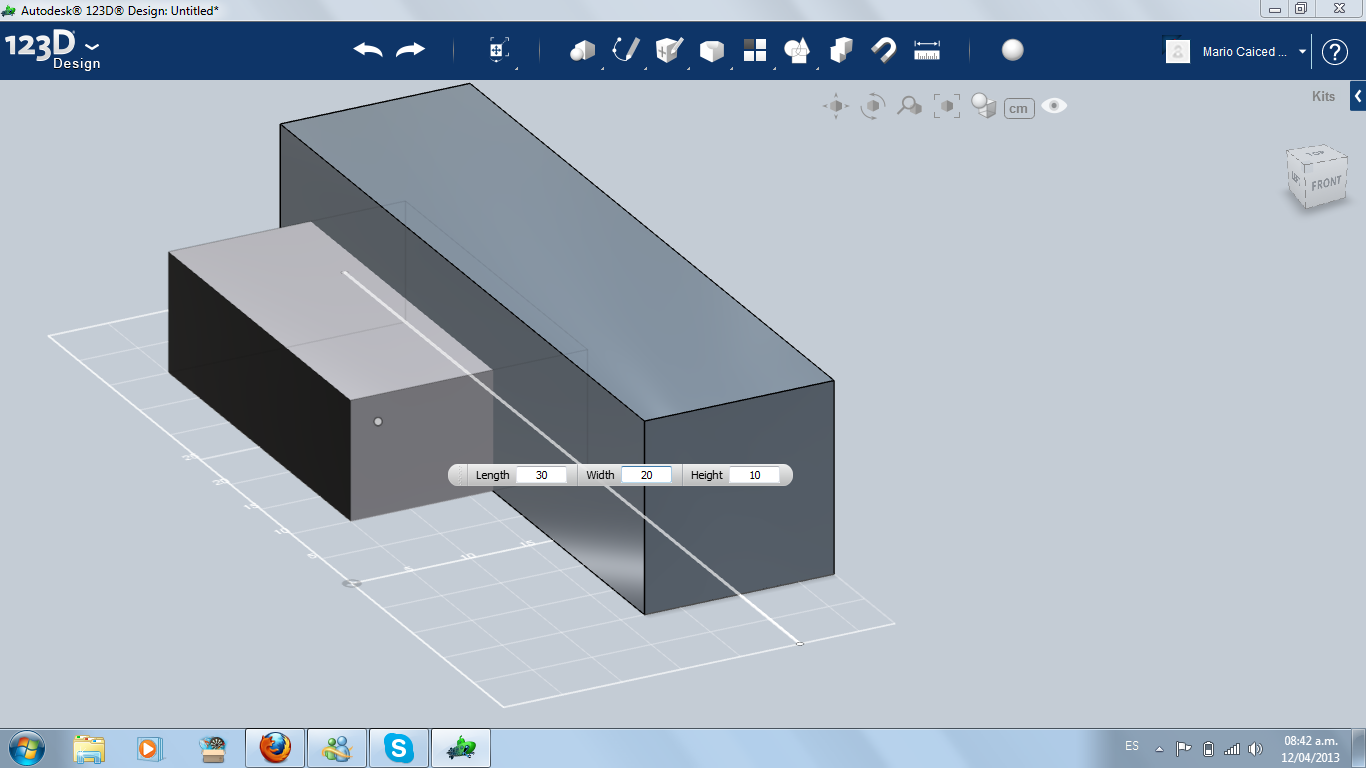
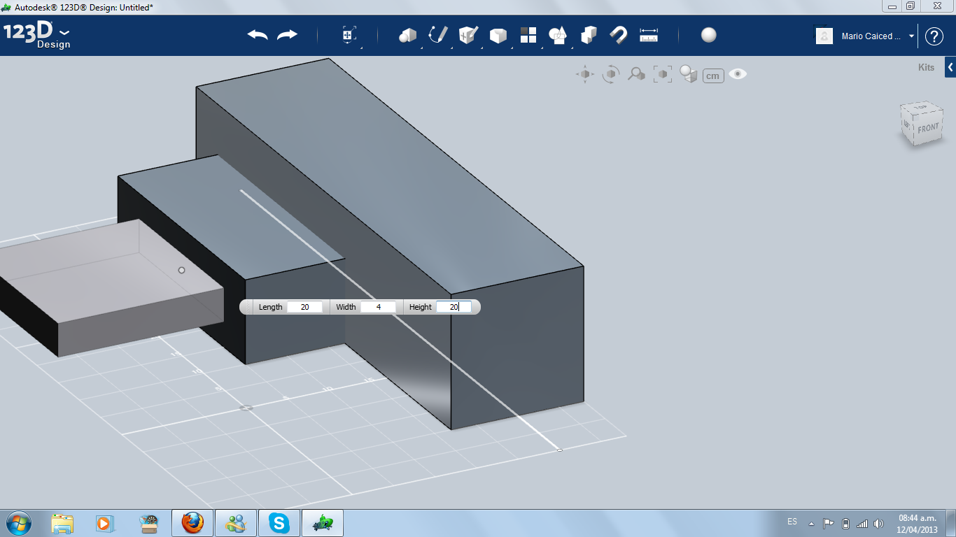
First: I drew a sketch line in the middle. It will be the baseline and mirror all of this instructable. I made one half of the jet in the left side of the line.
I started with three primitive boxes: the bigger will become the fuselage, the middle one will be the air intake and the thinner one, the wing.
NOTE: In the first steps, the baseline will be in the center of the fuselage, just for seeing the size of the cockpit. Later, you will see I cut almost all beyond the line and worked only in the left side.
Modeling the Front Part
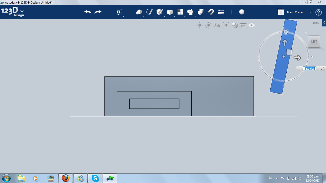
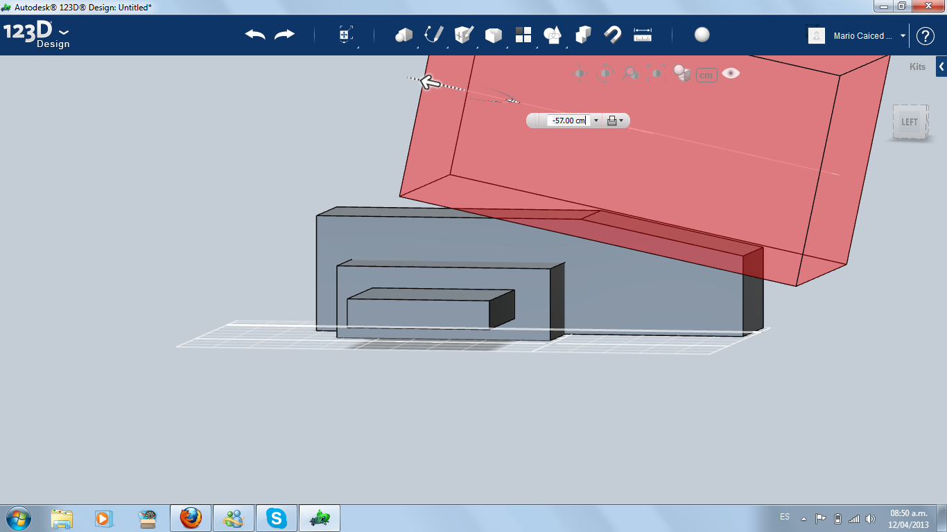
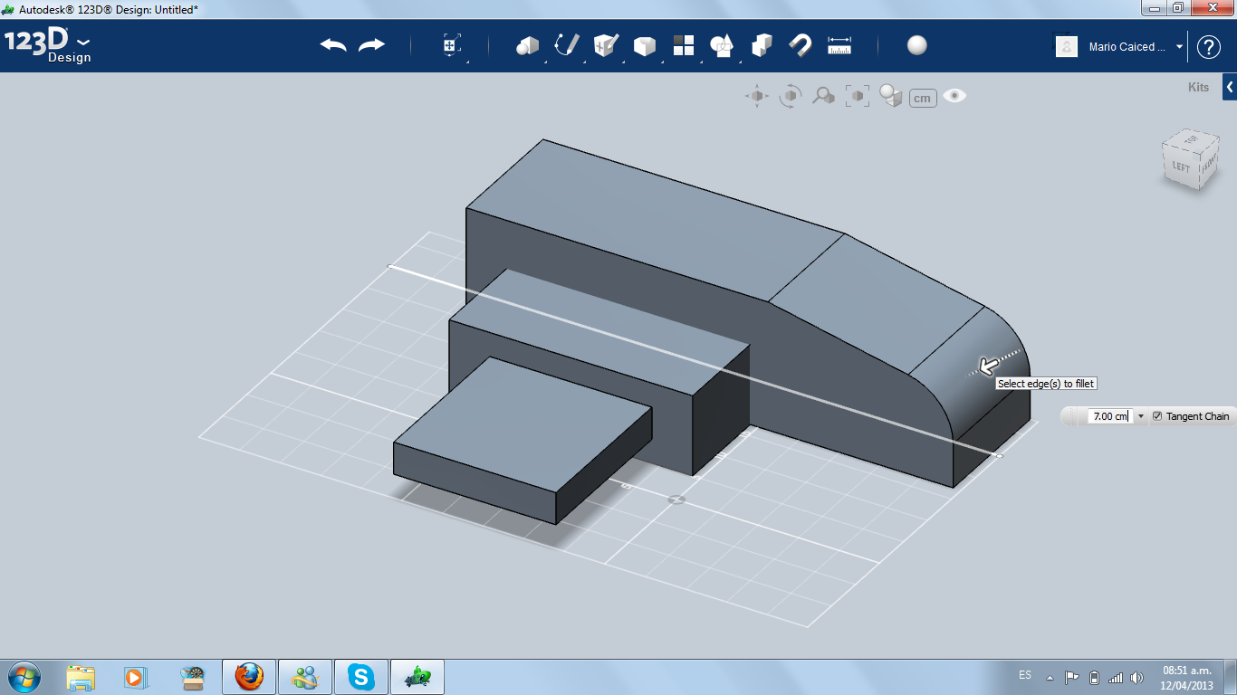
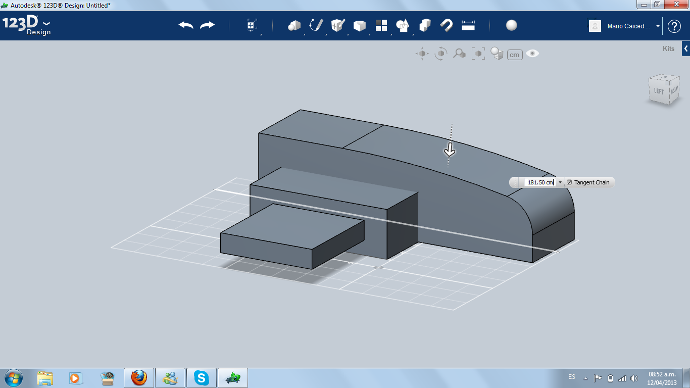
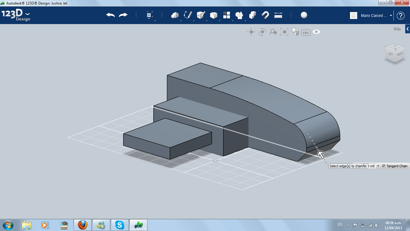
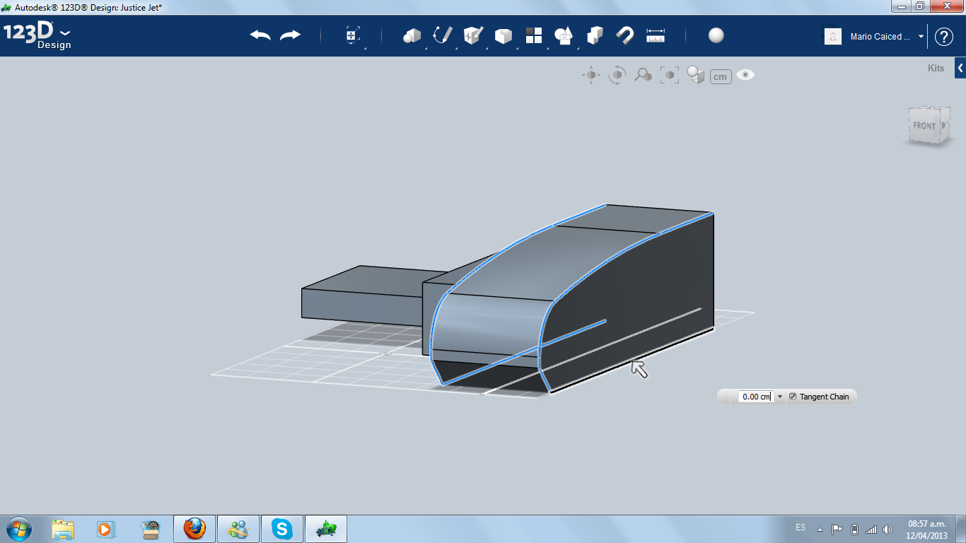
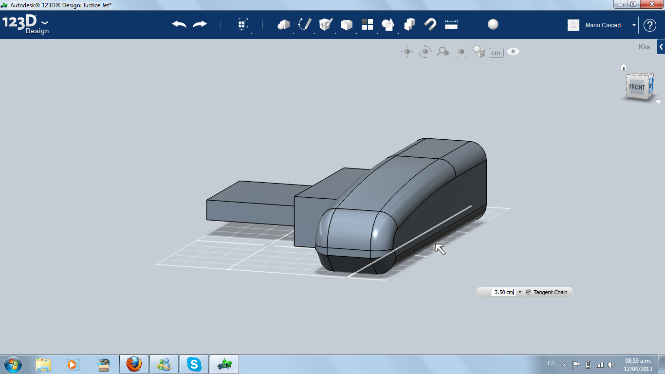
Using Extrude, Fillet and Chamfer, I started modelling the front part (cockpit).
Outlining the Wing
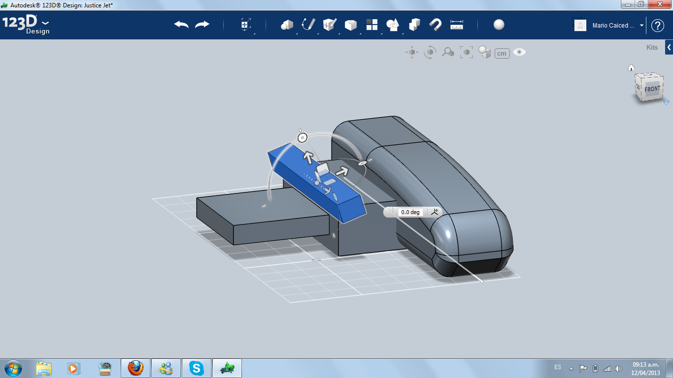
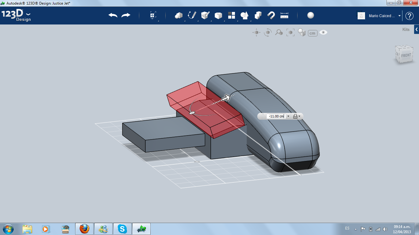
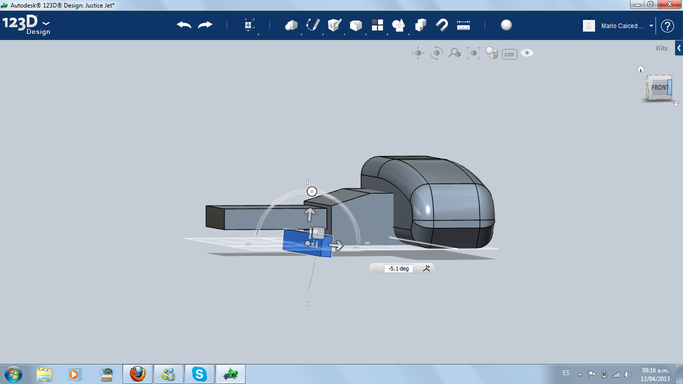
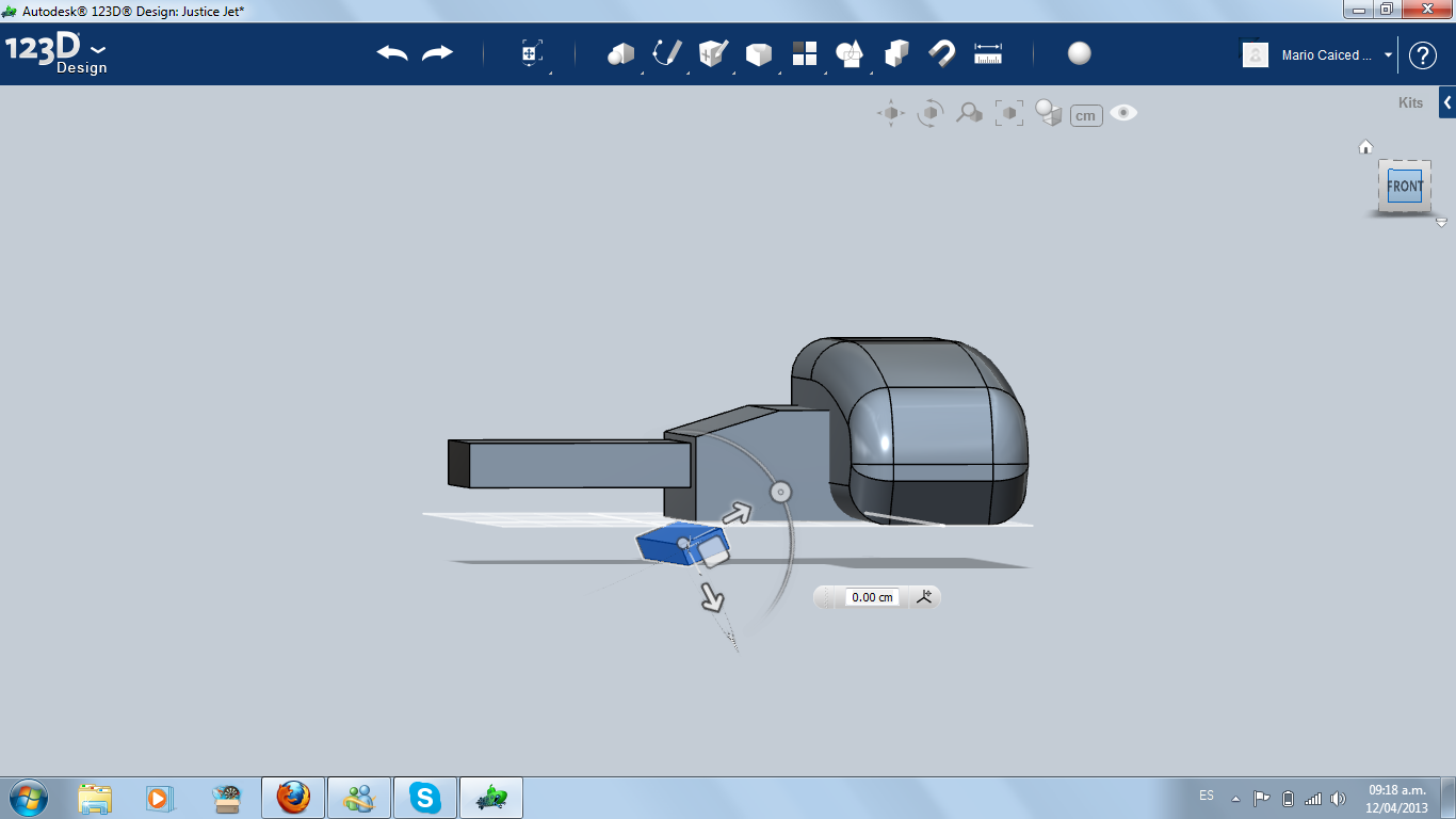
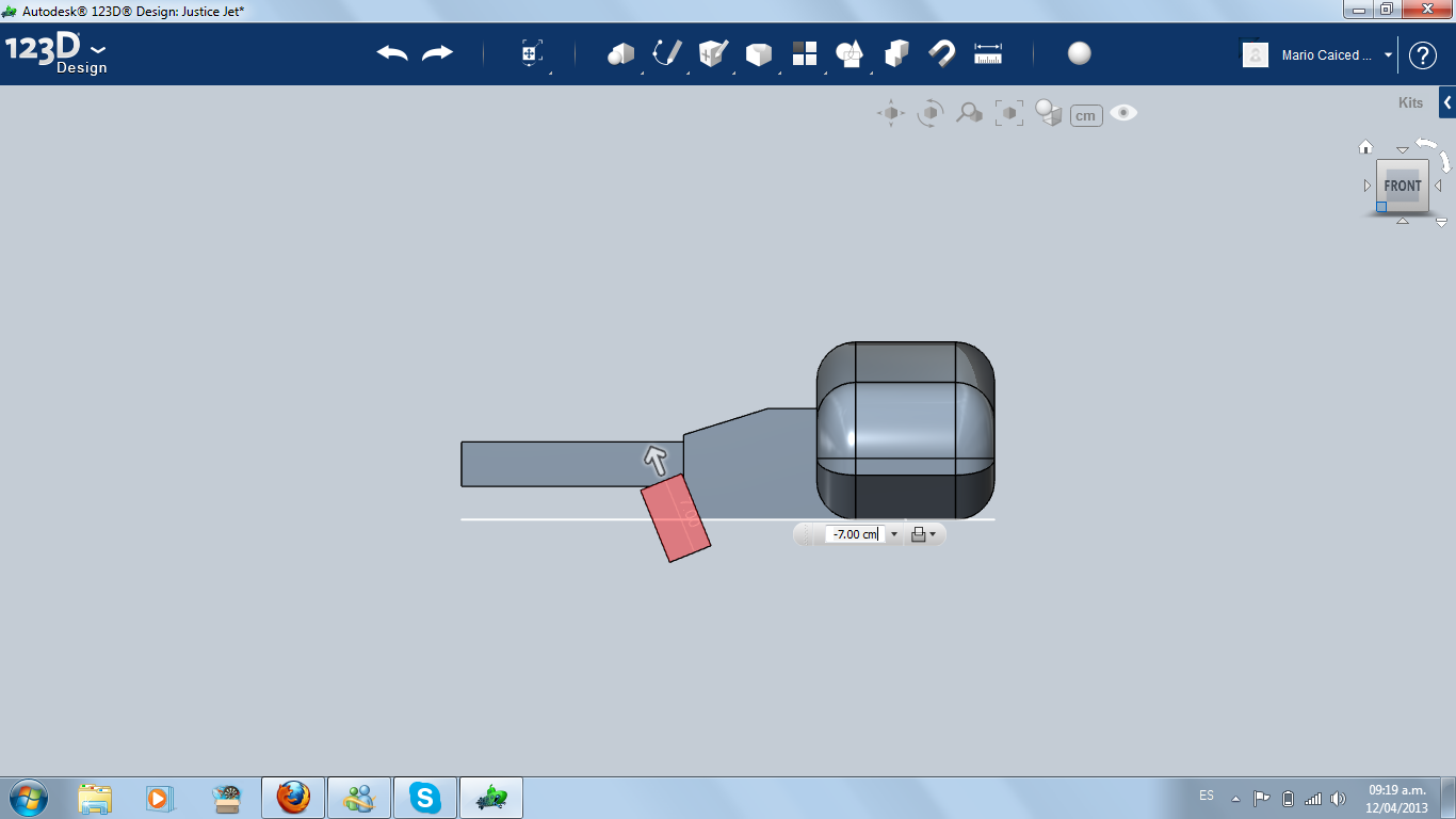
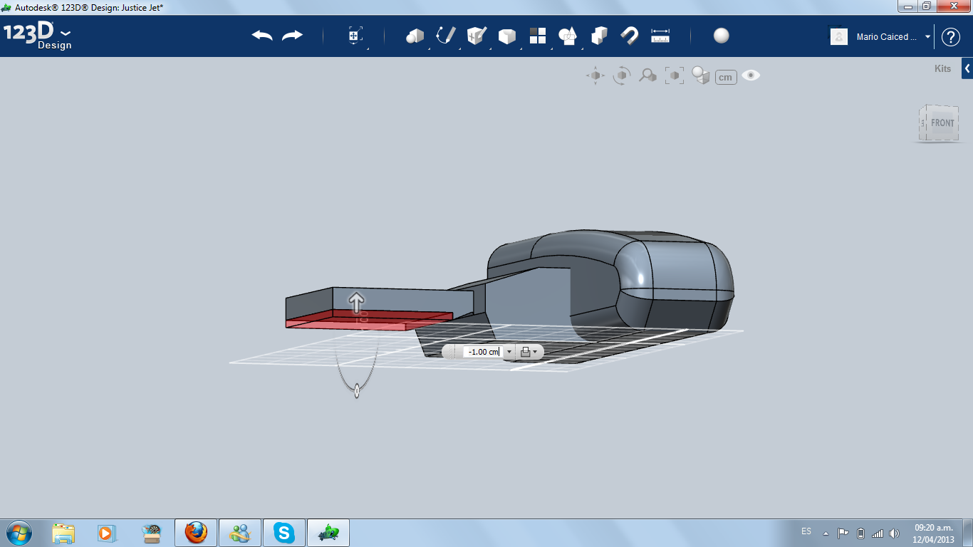
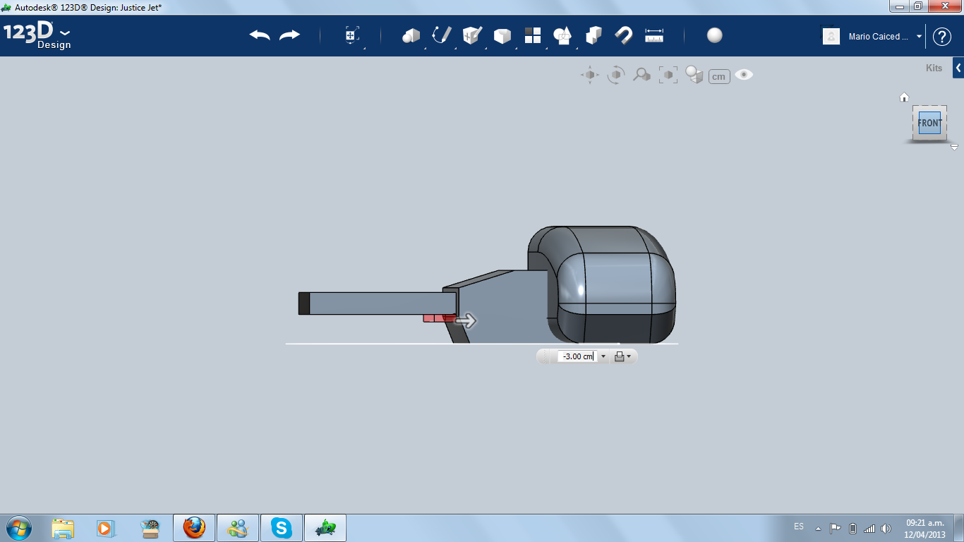
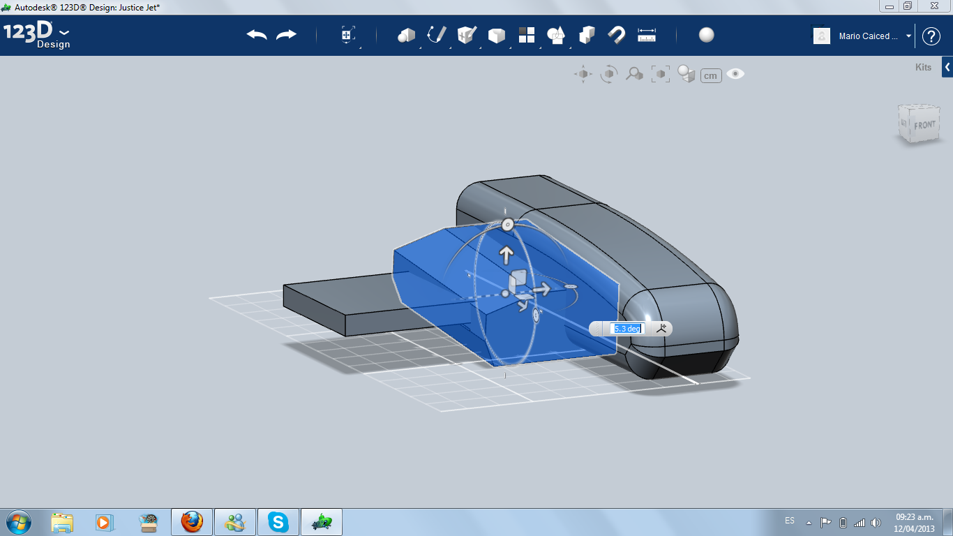
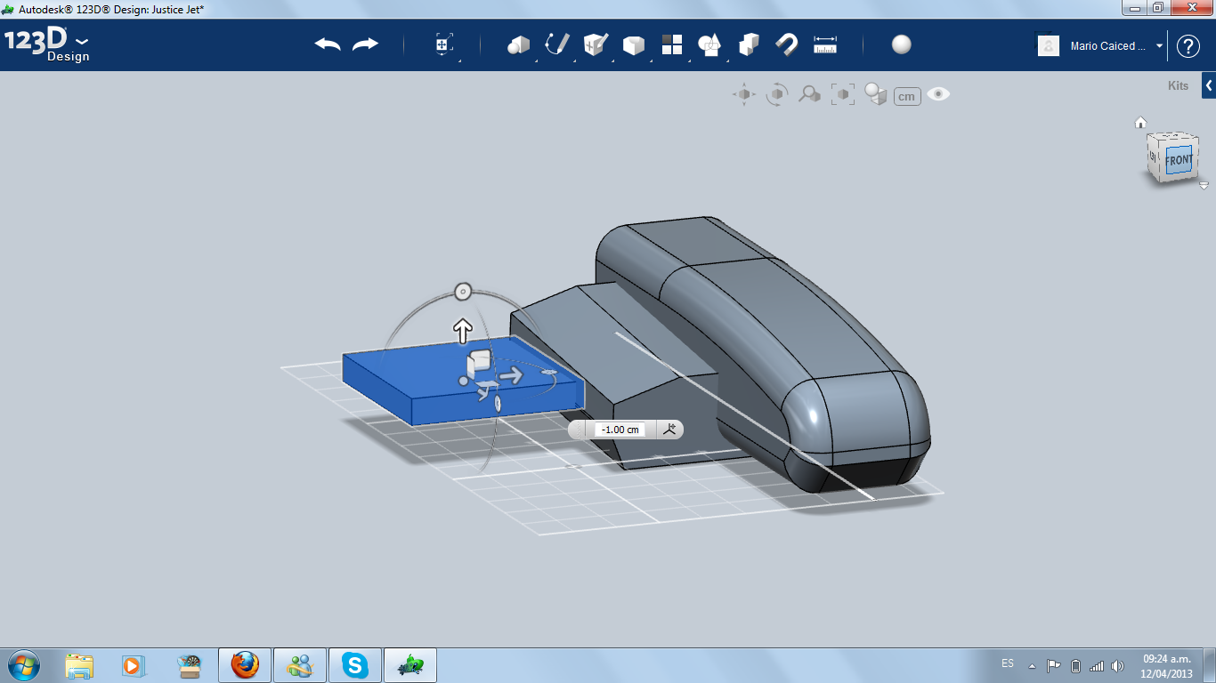
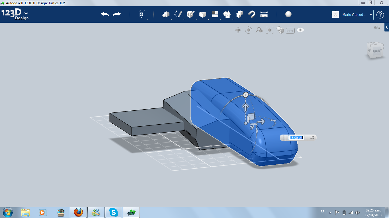
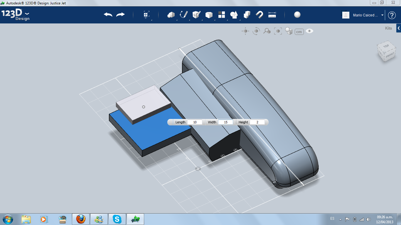
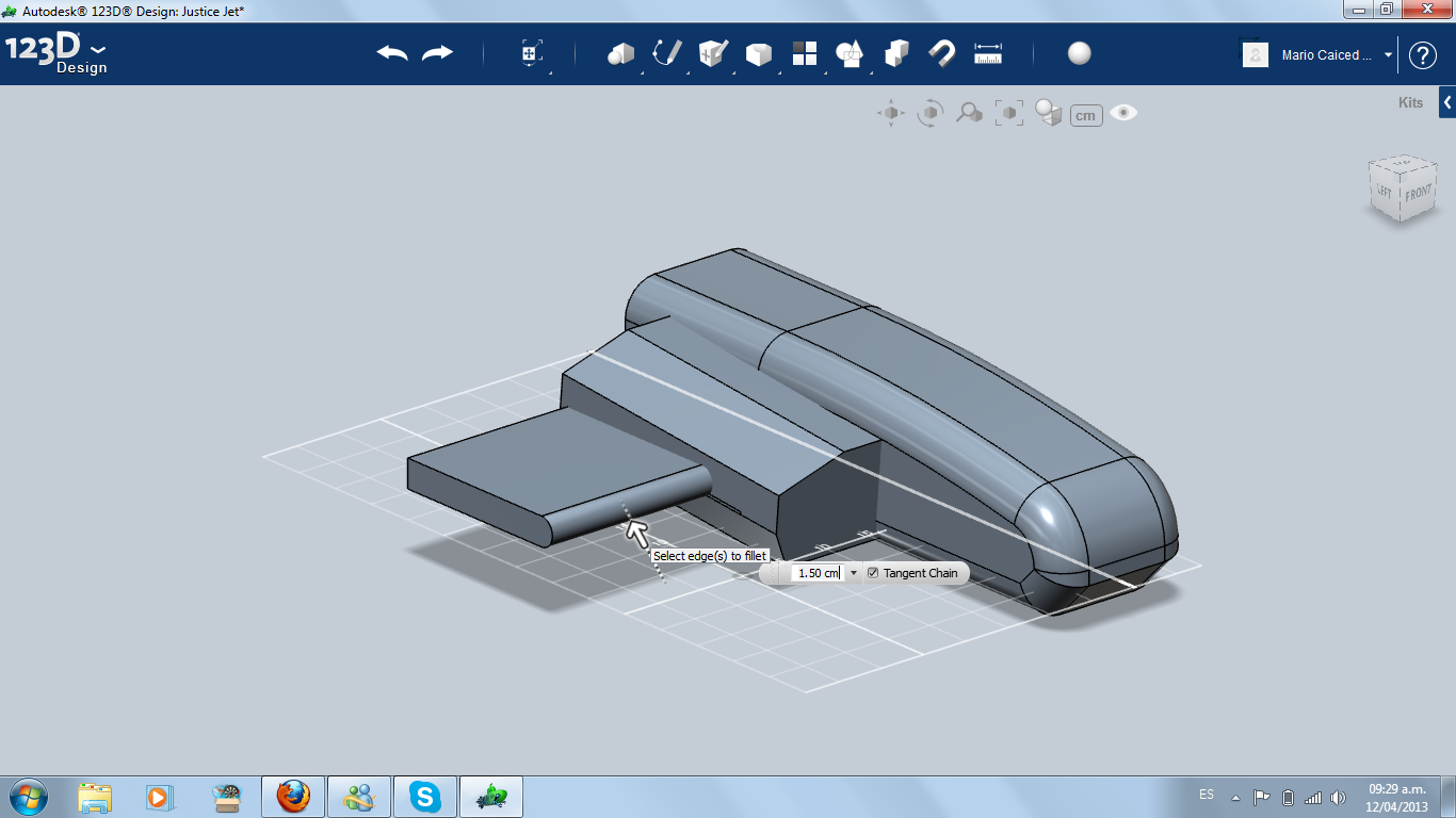
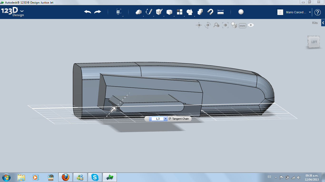
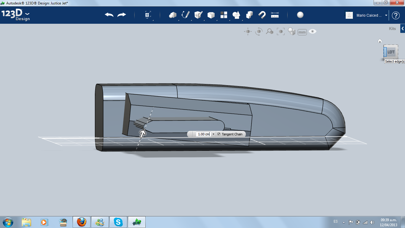
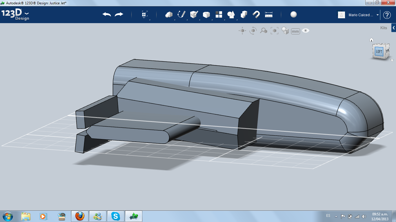
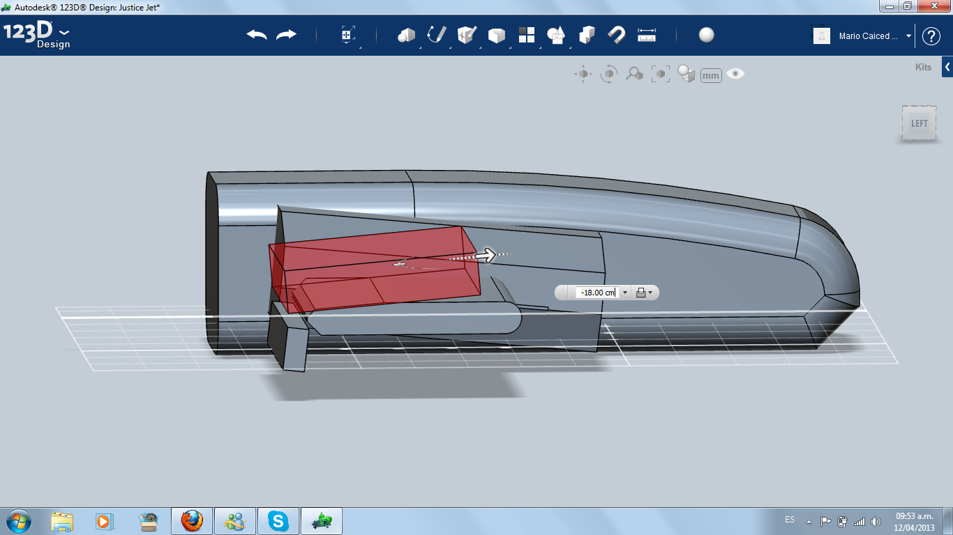
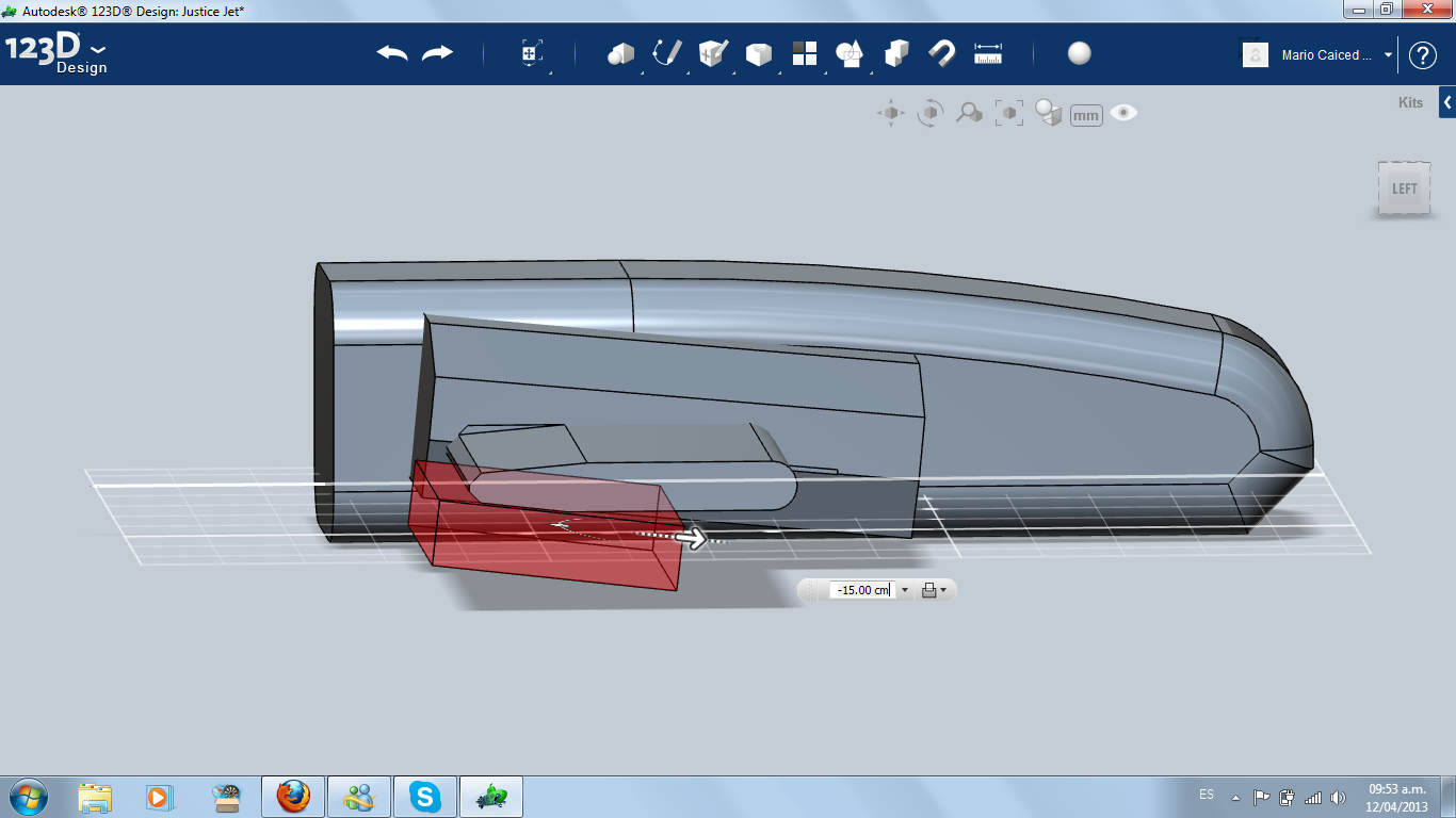
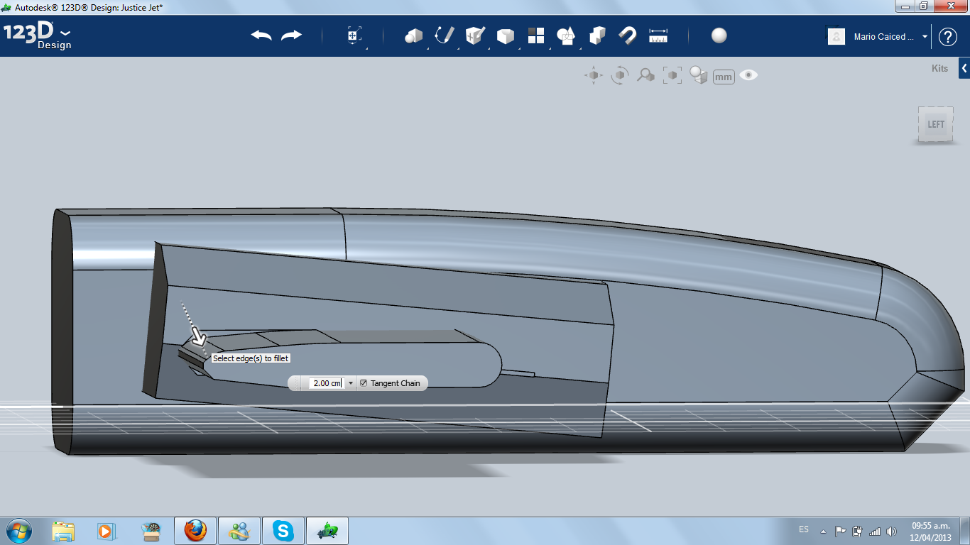
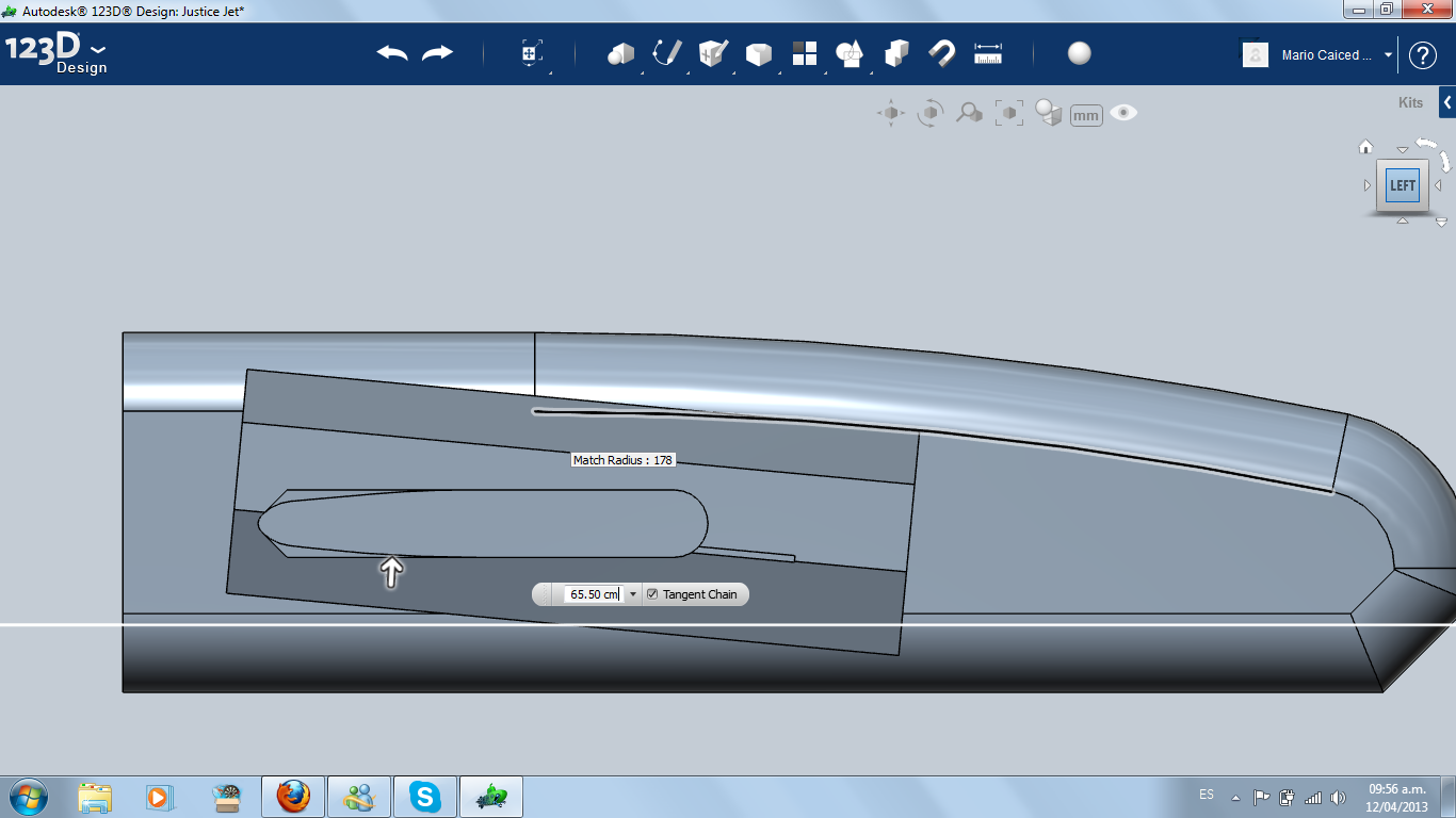
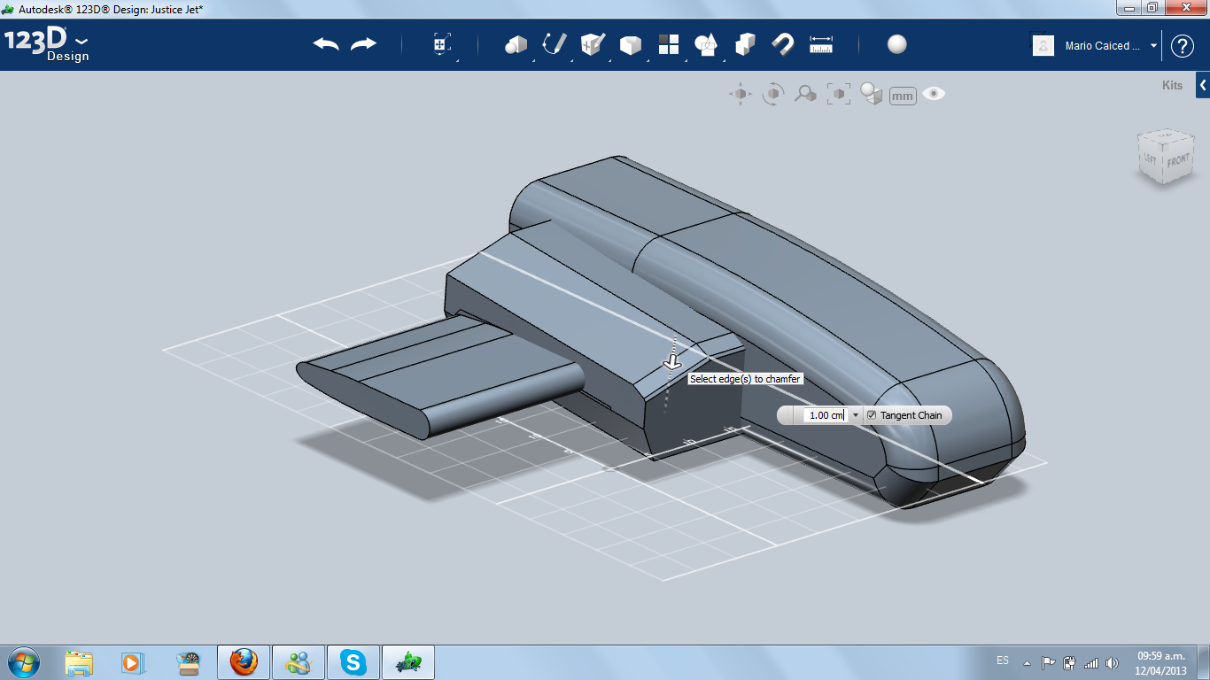
Now it's time to giving the wing and the air intake box some aerodynamic shape, using Extrude, Chamfer and Fillet. That means to change the air intake angle and the thickness of the wing, giving a razor shape to the last one, with the thickest part in front (airfoil).
Back
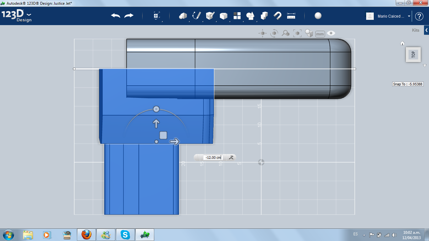
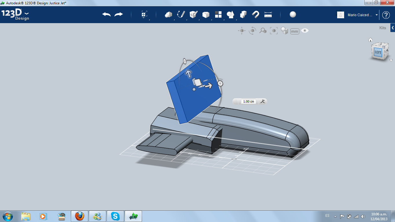
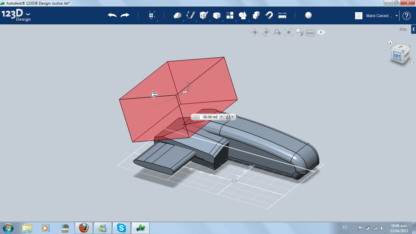
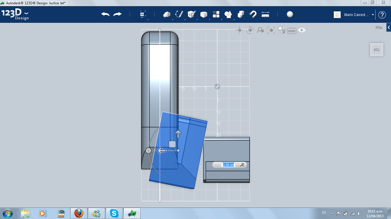
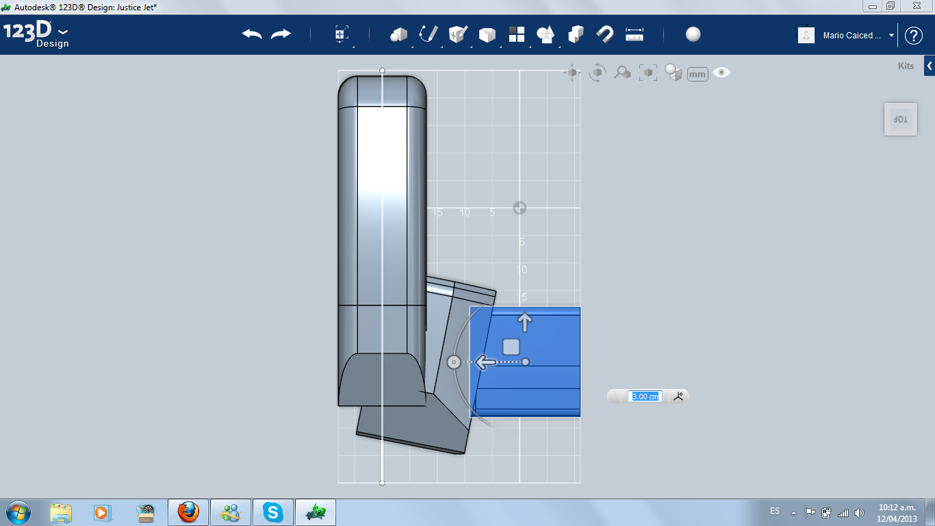
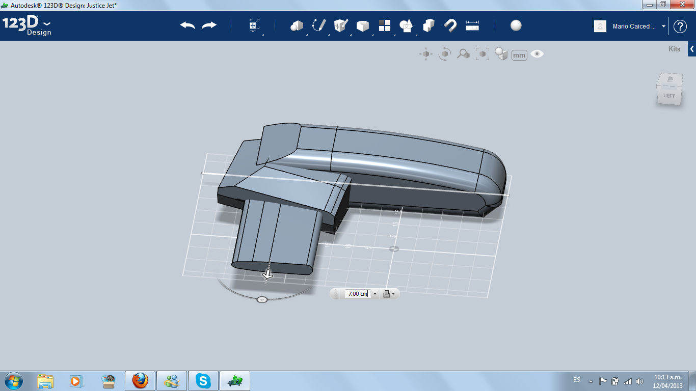
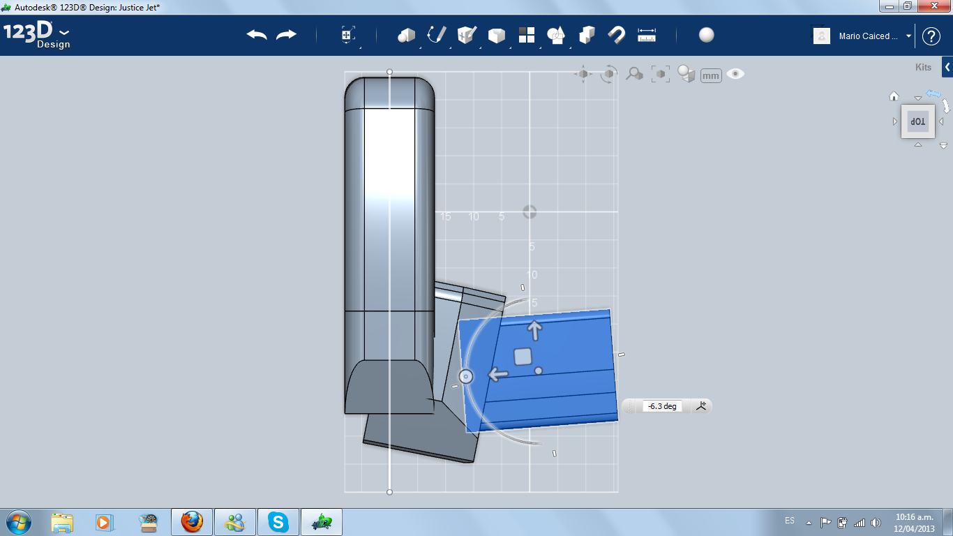
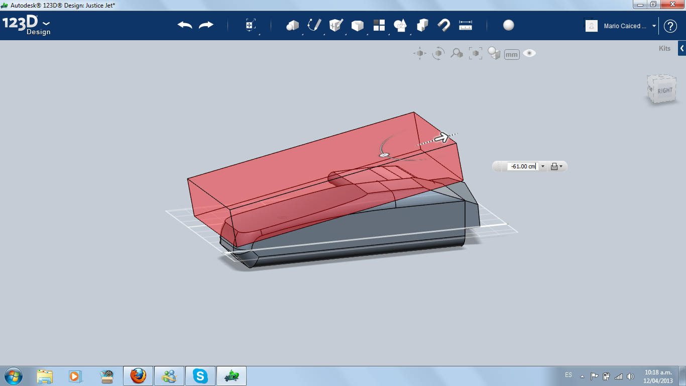
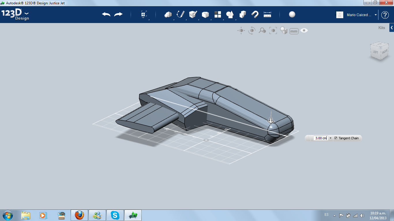
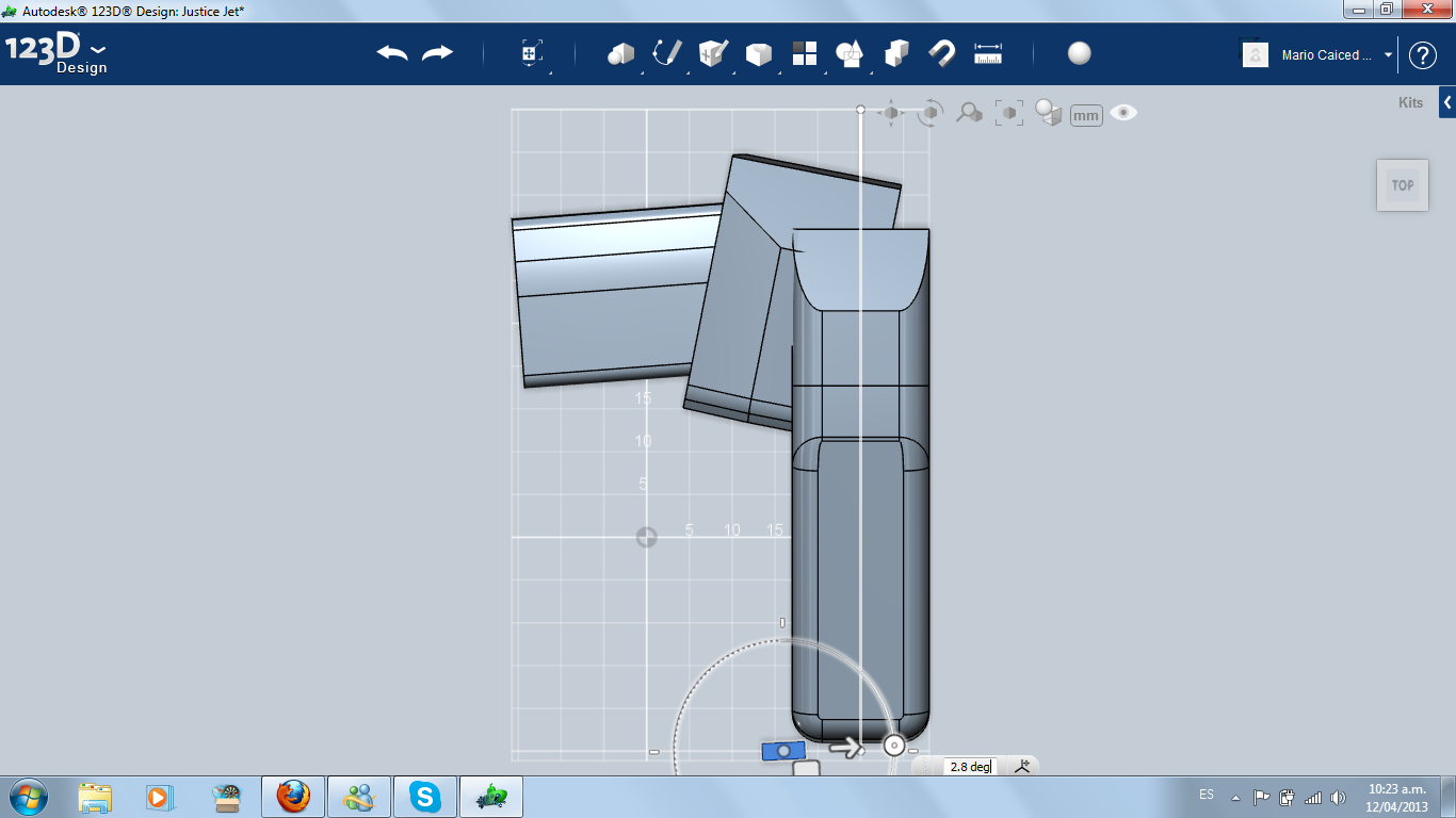
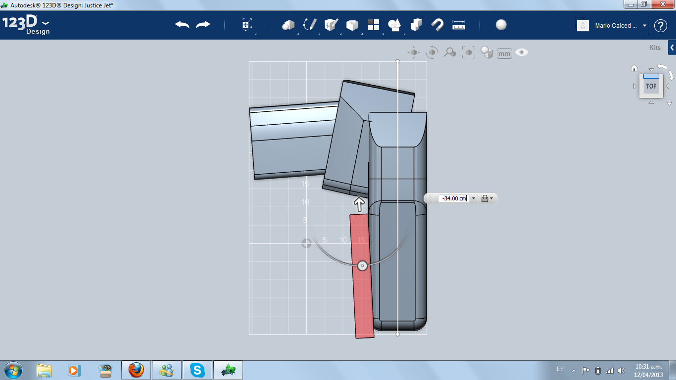
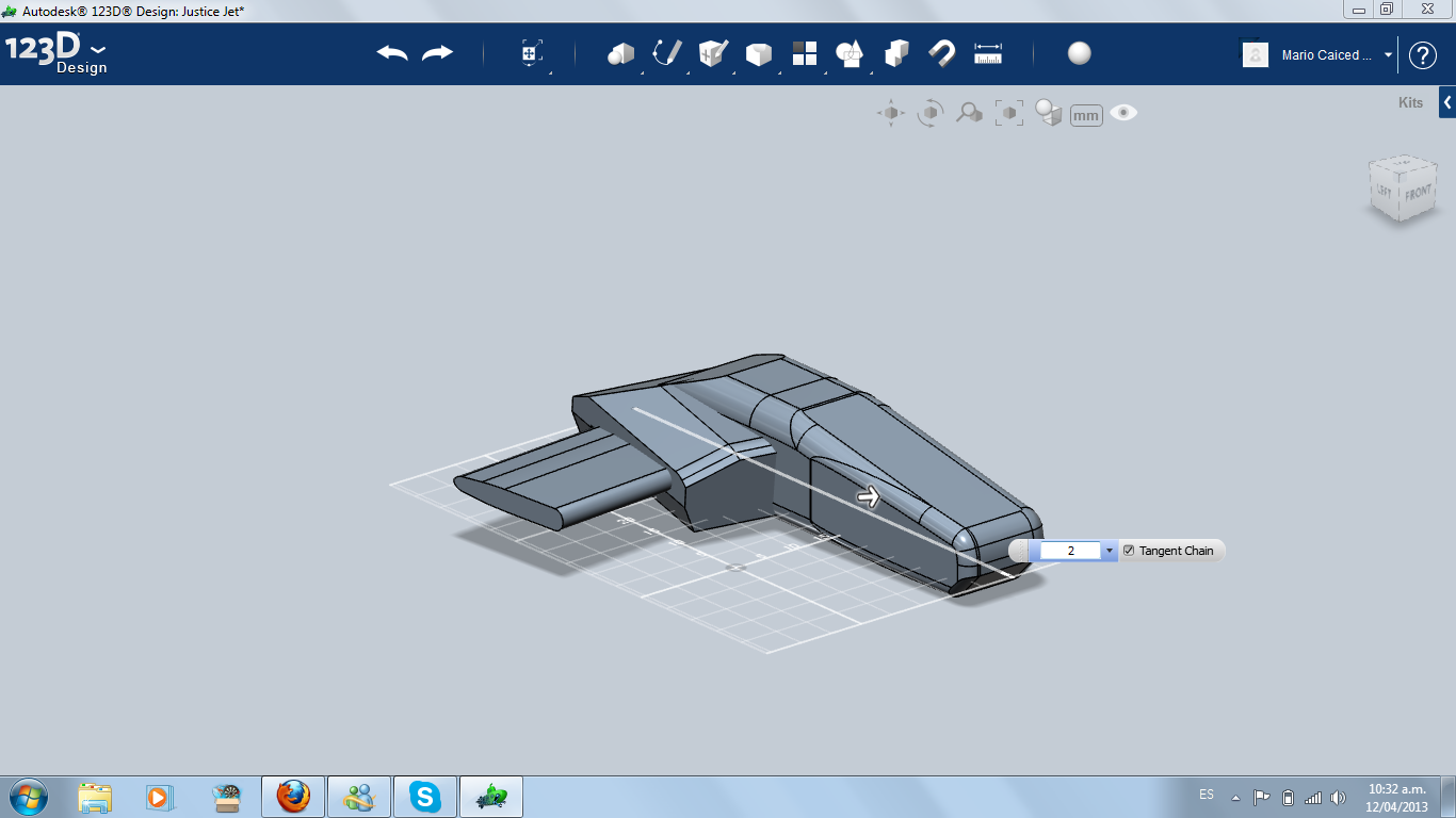
I started outlining the back changing the attack angle of the air intake box (and the wing). Then I started to work on thefuselage shape.
Stabilizer
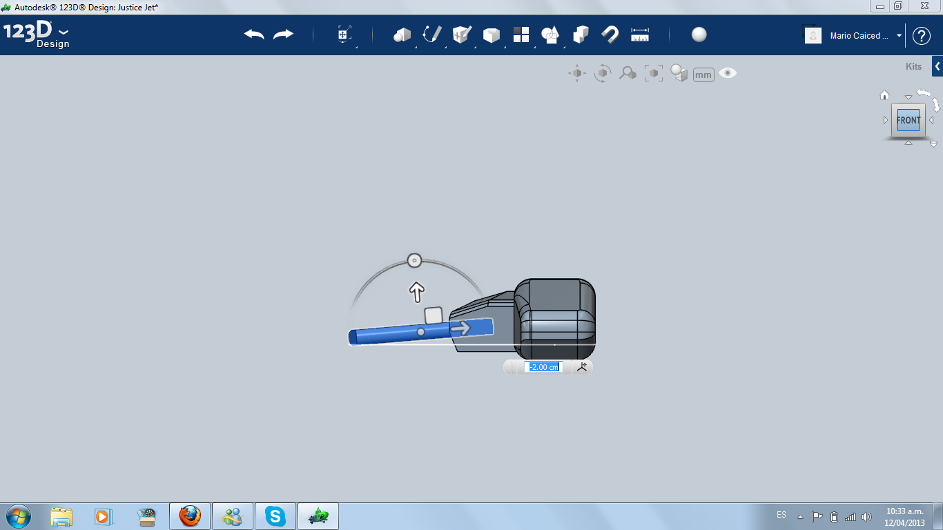
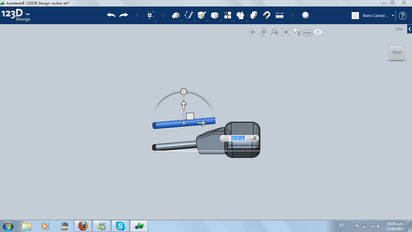
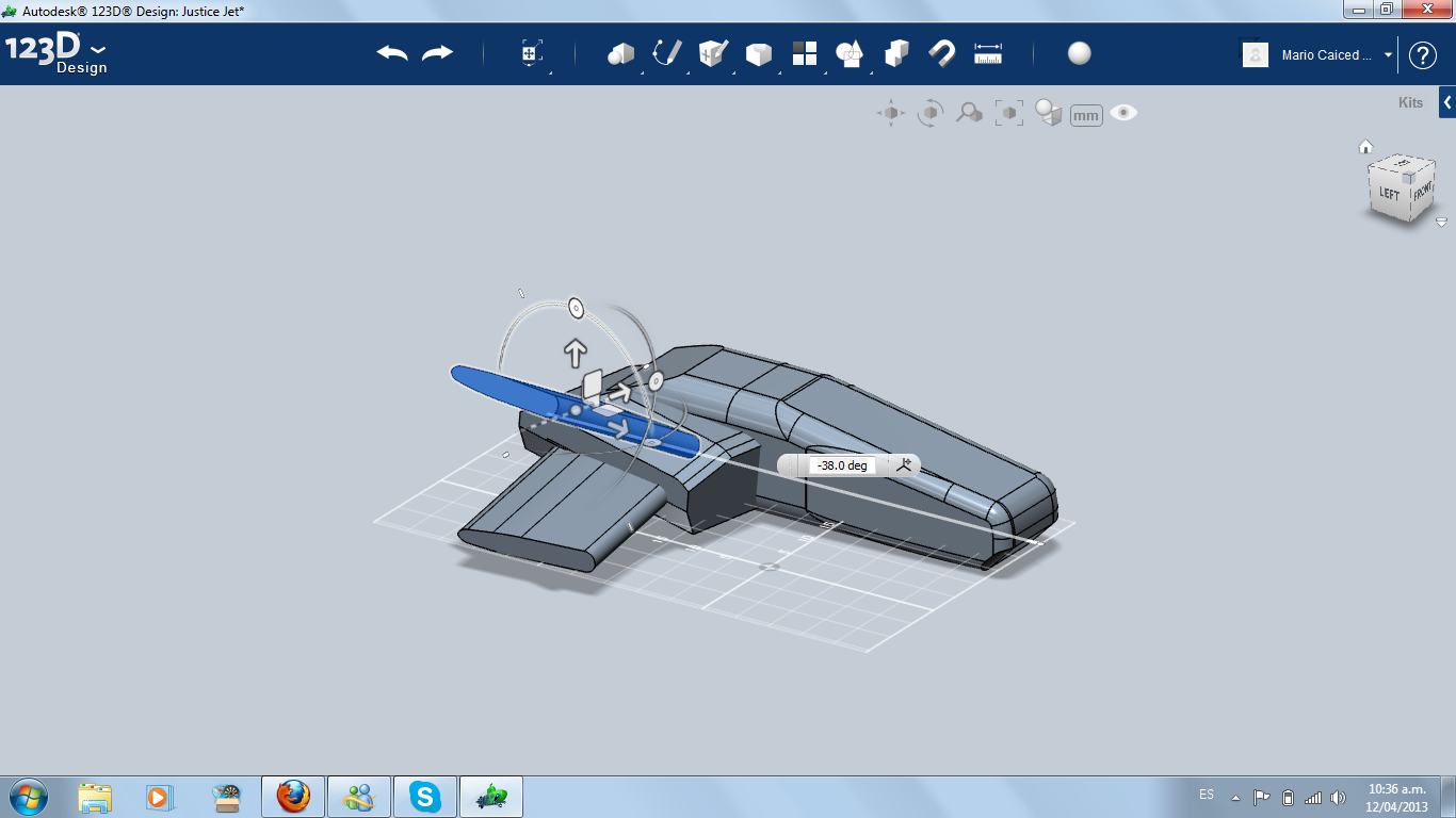
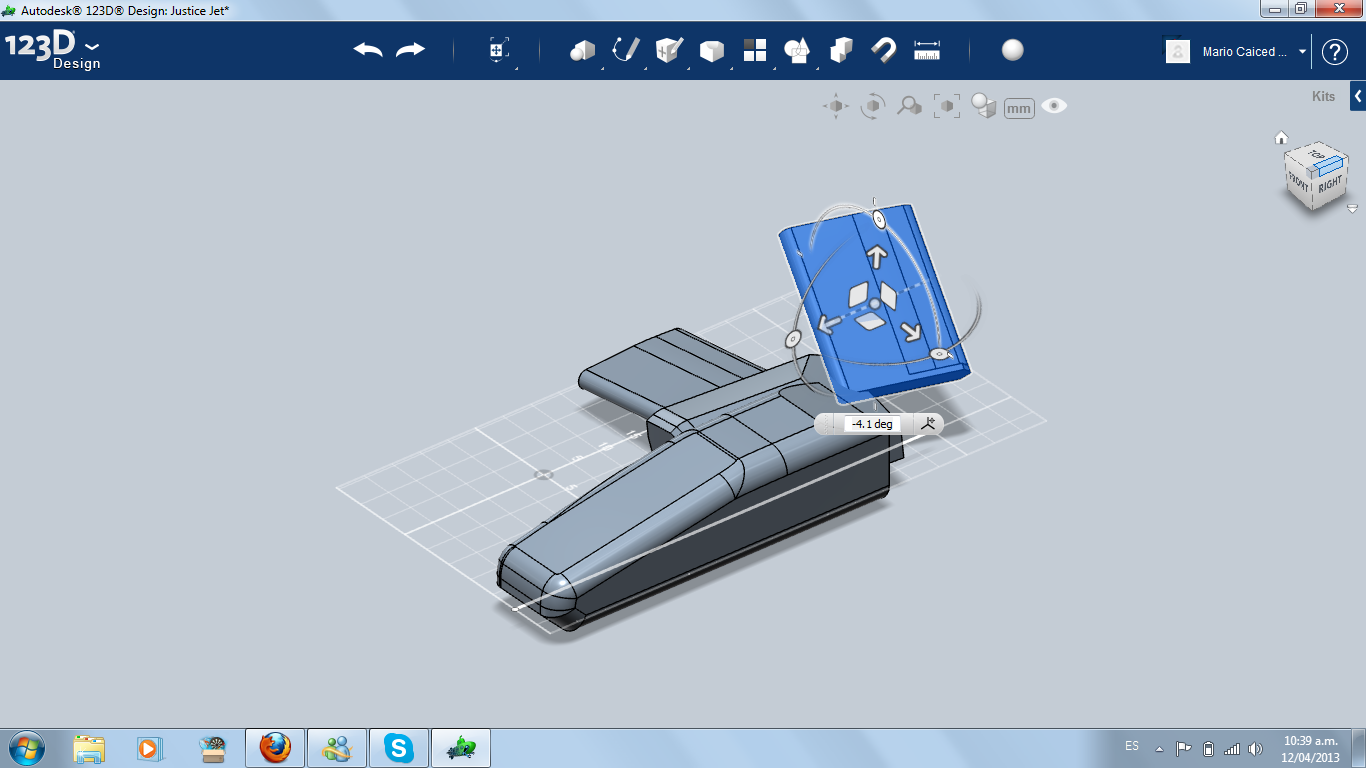
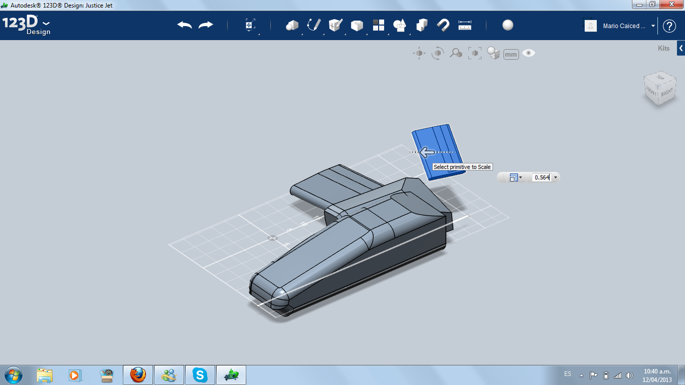
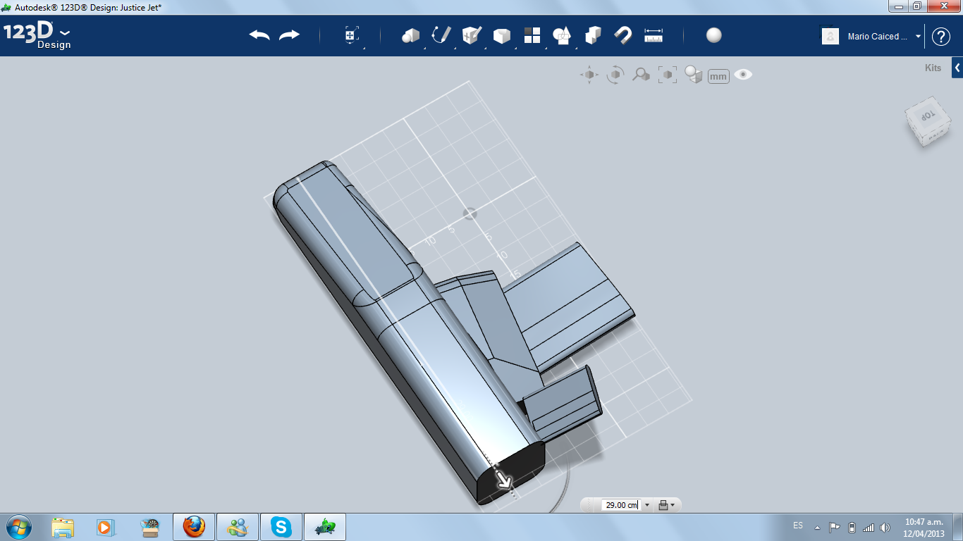
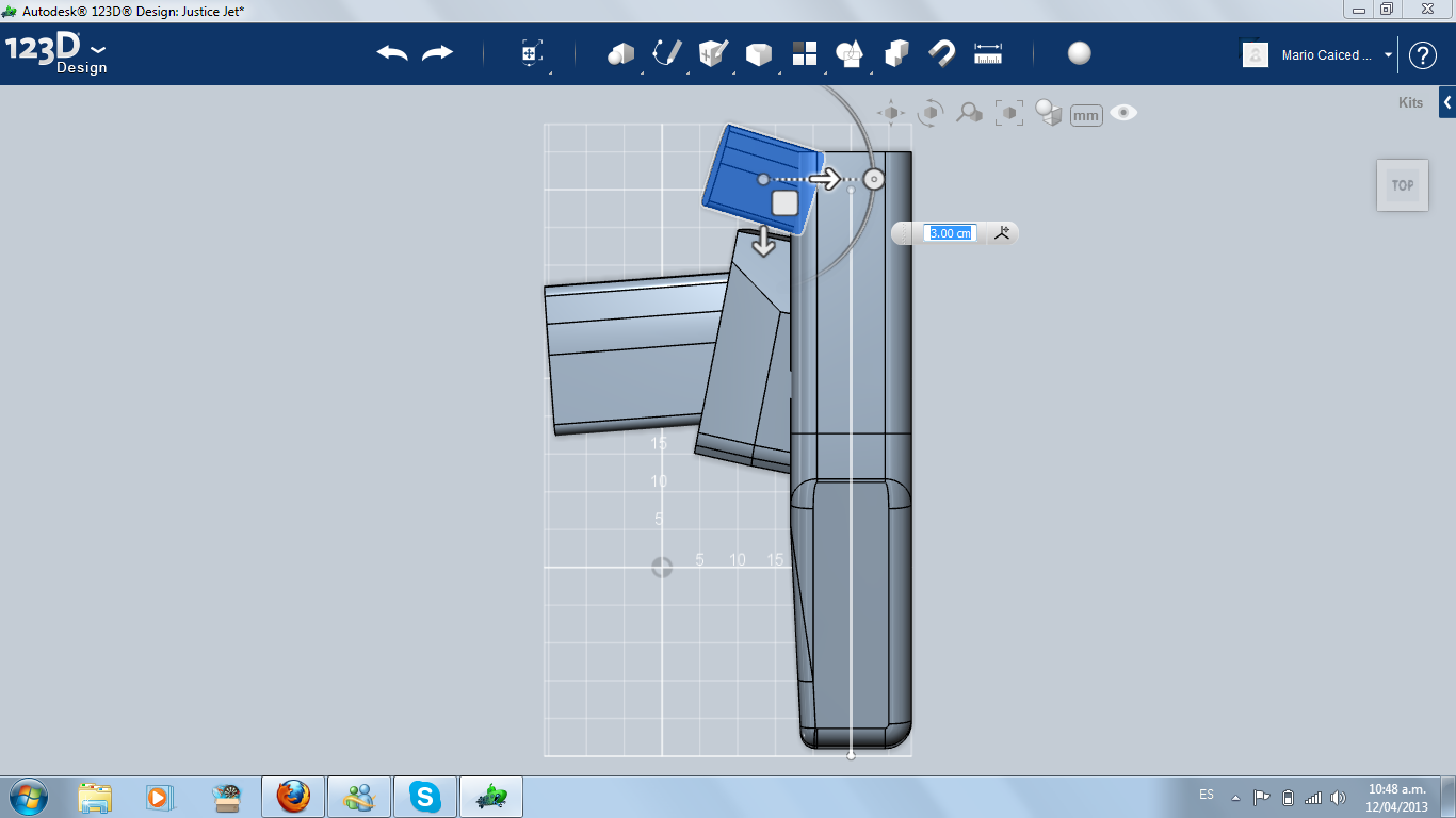
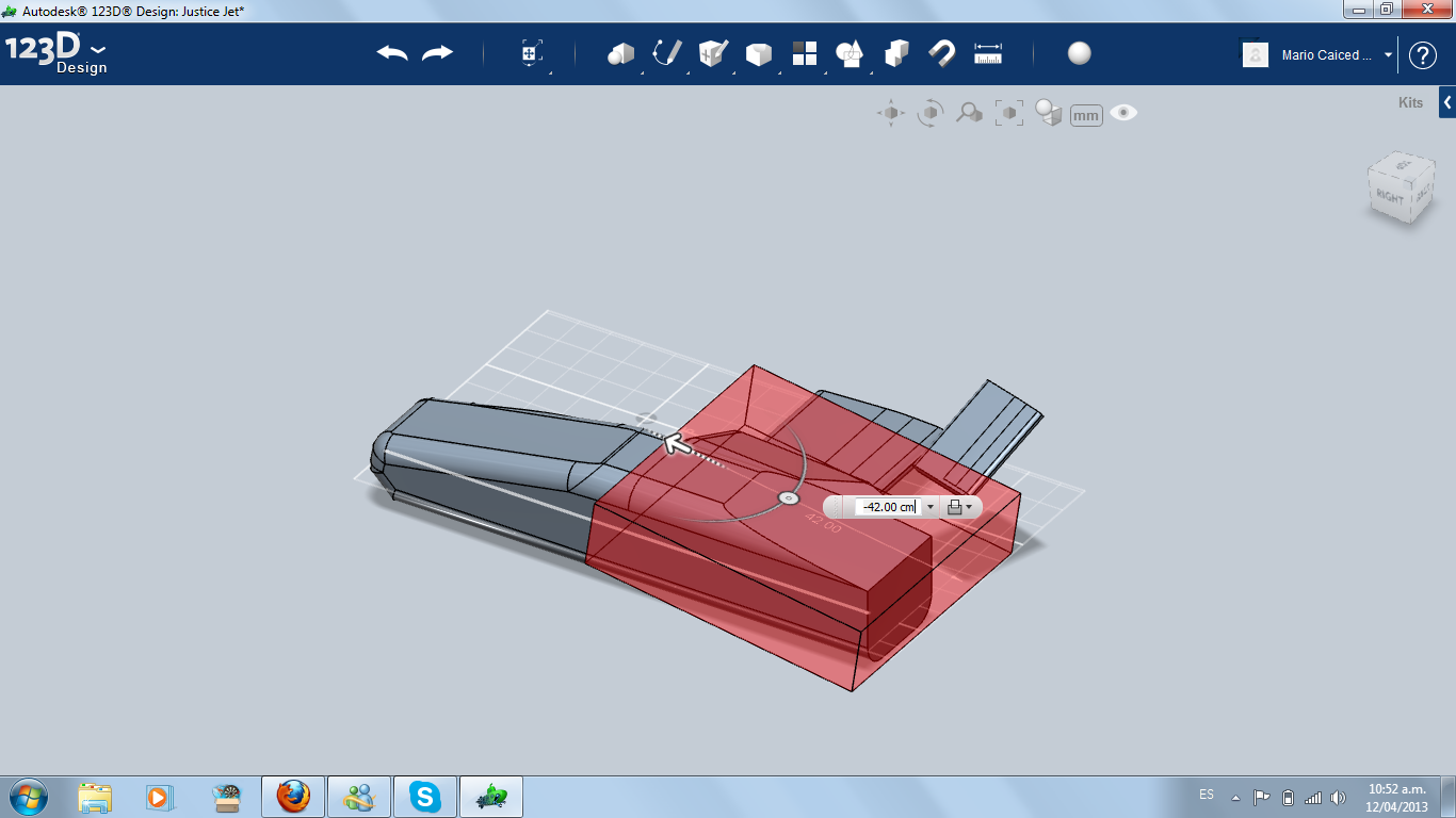
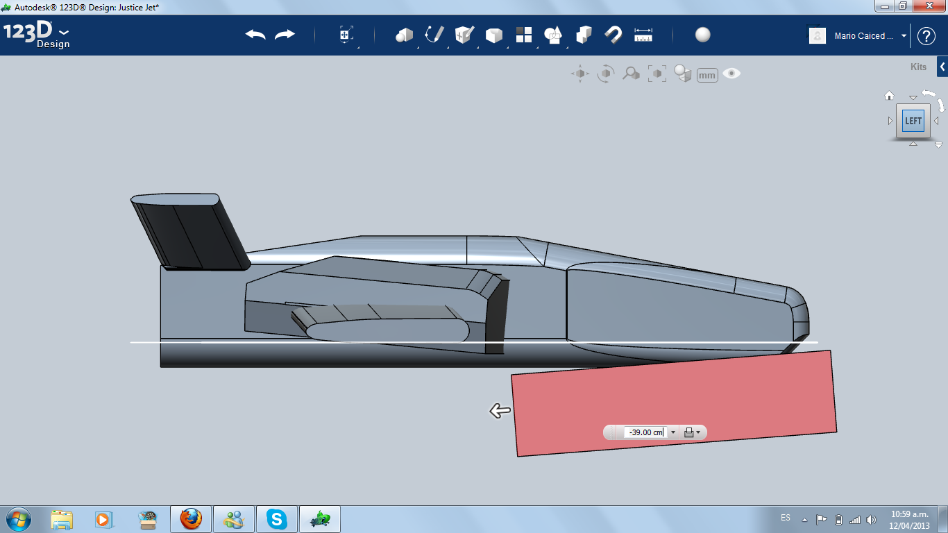
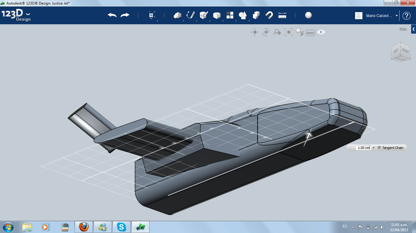
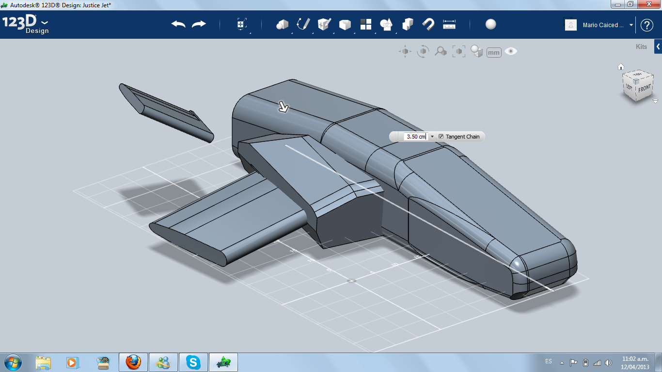
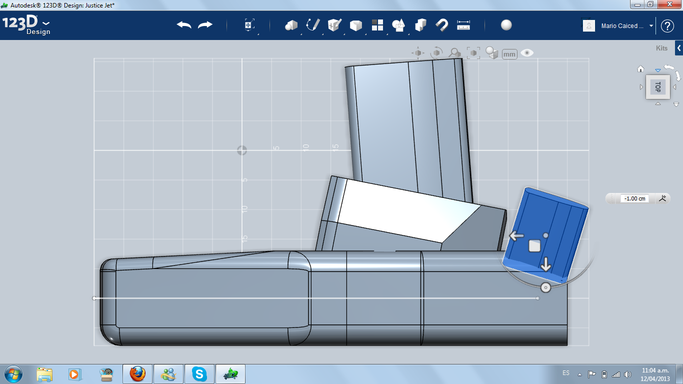
The easiest way of making the stabilizer is copying the wing and reducing the size, using tool Scale. Then, put the new smaller wing in the back, adapting the shape of the fuselage according to the stabilizer position.
Working the Fuselage
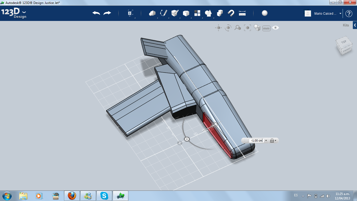
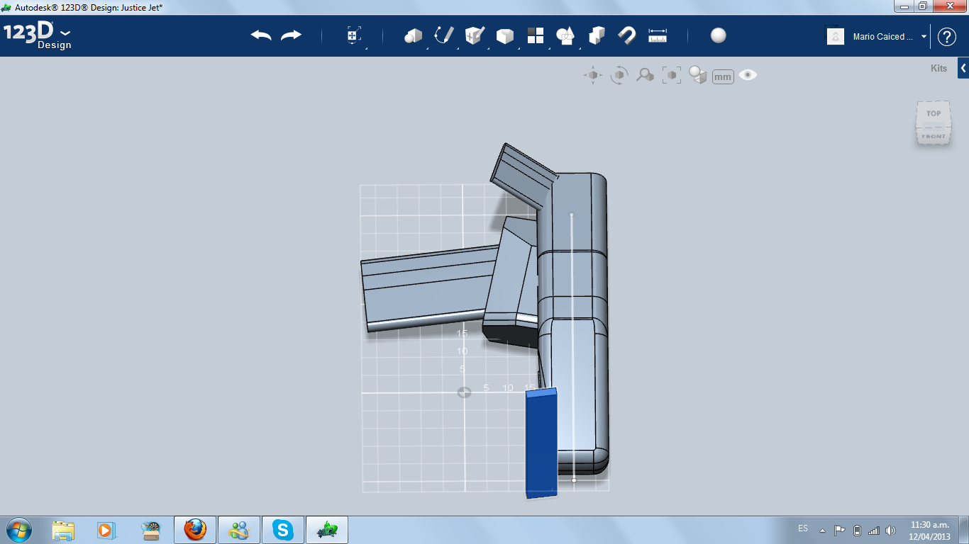
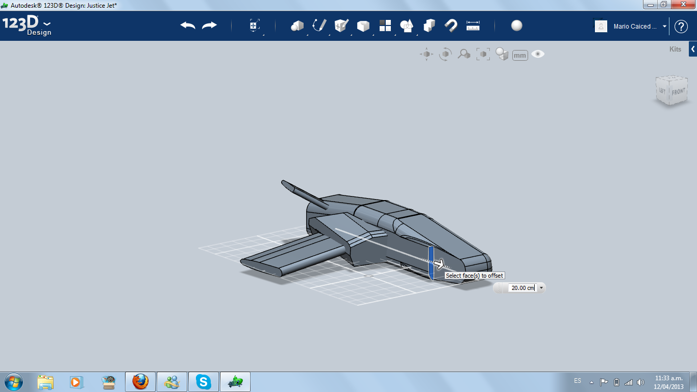
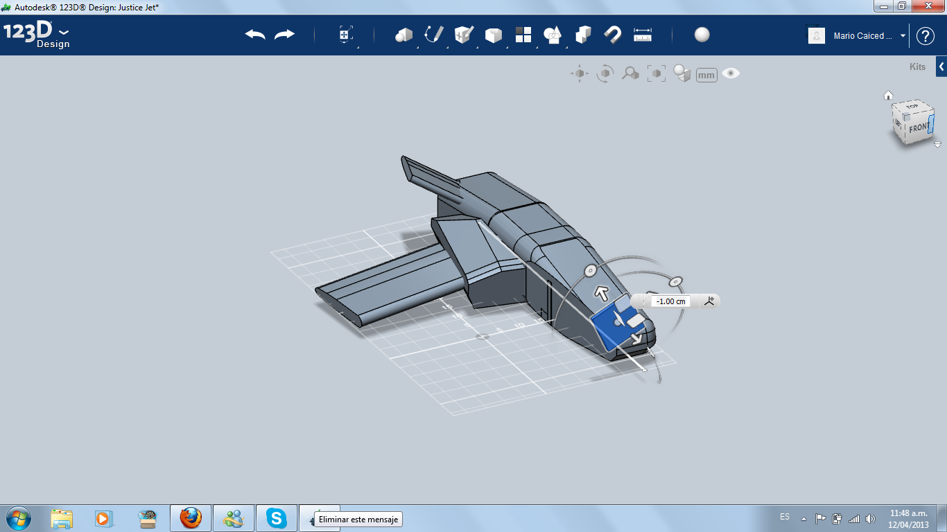
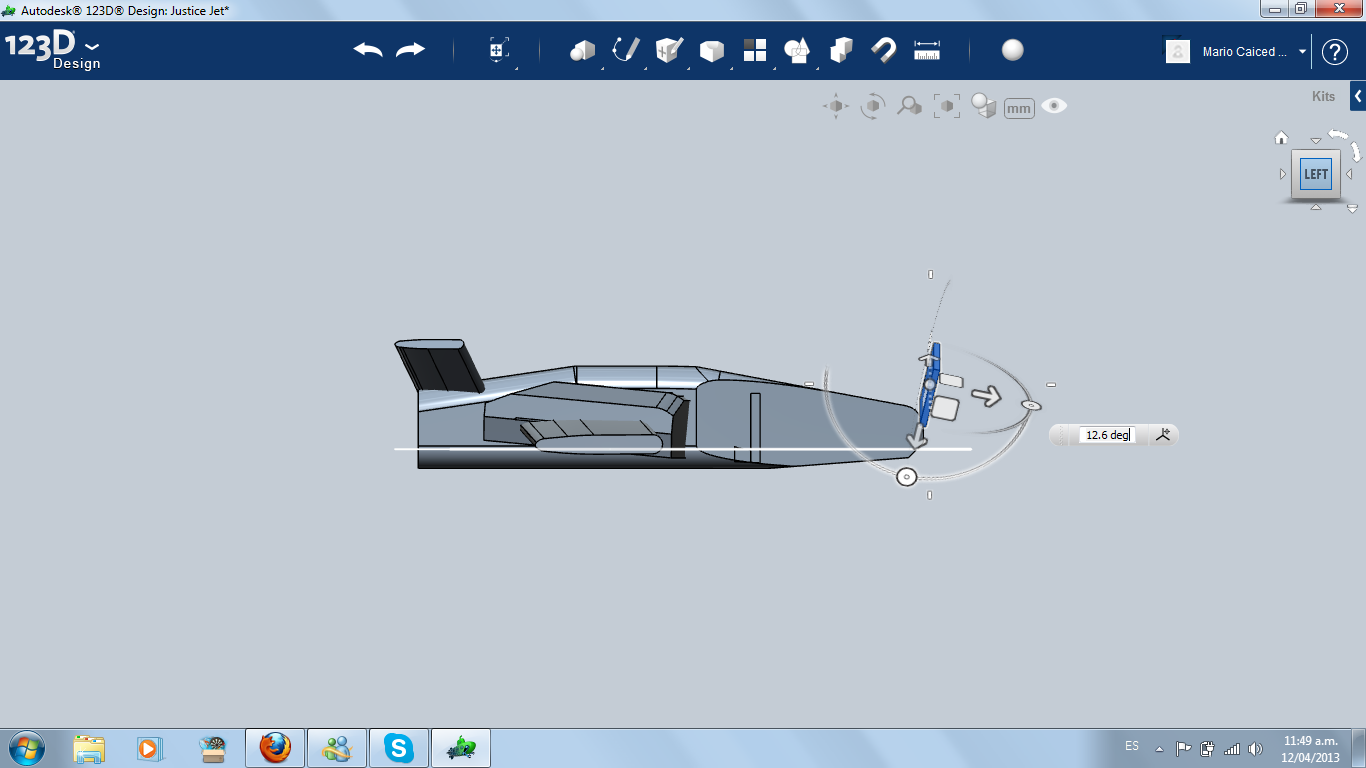
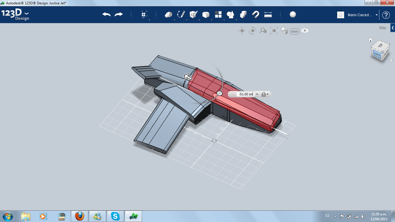
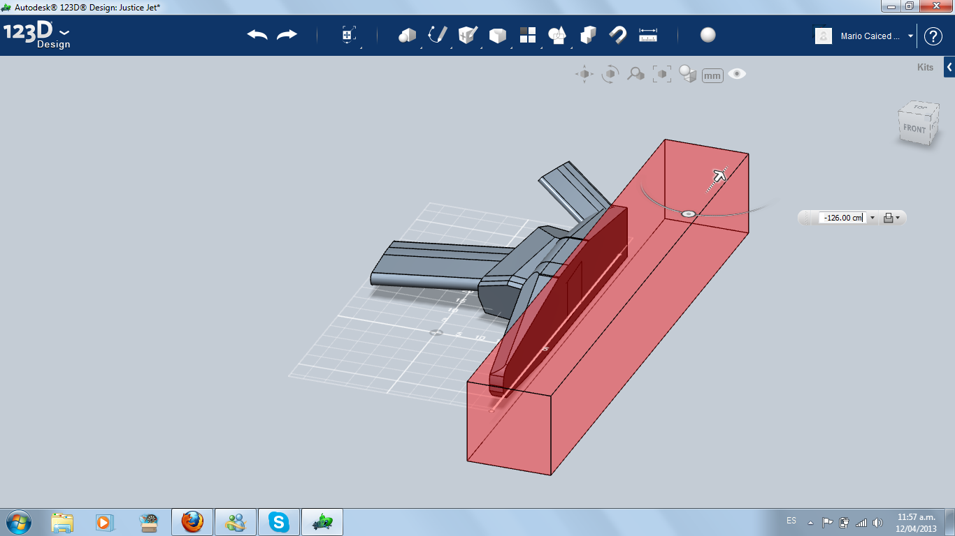
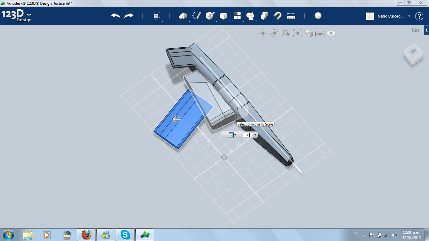
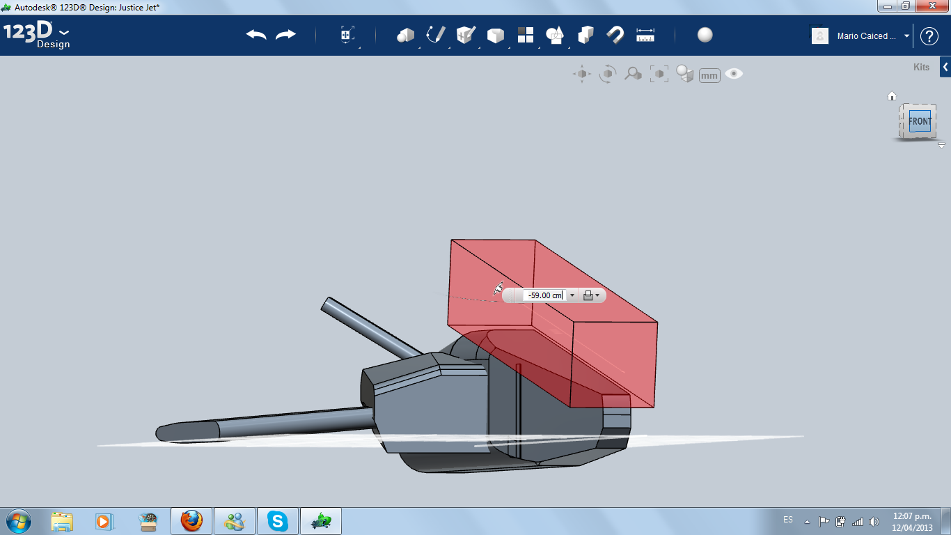
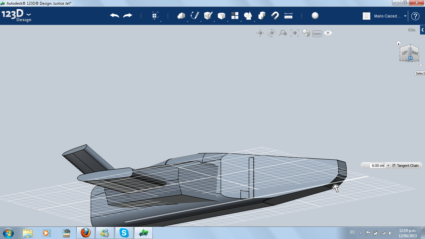
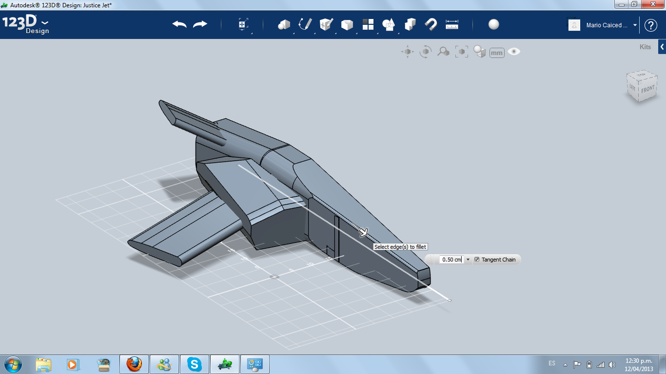
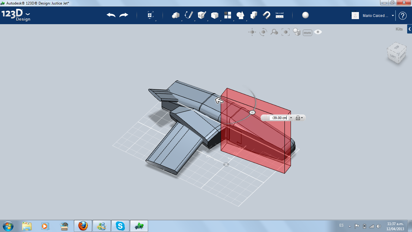
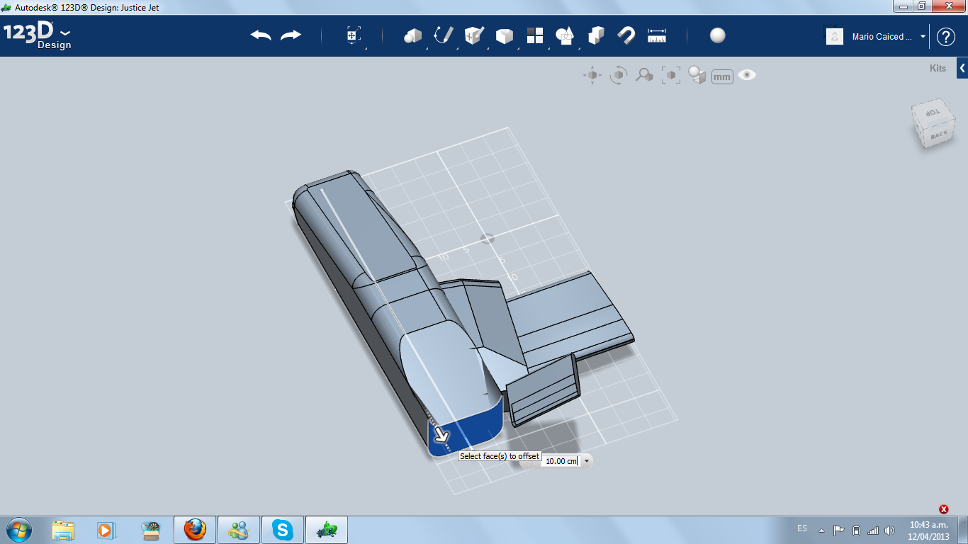
At this point I continued modifying the cockpit and the fuselage, experimenting shapes, filleting and chamfering, and changing the attack angle of the wing when necessary. It's time to erase the right side of the fuselage and working only in the left.
Air Intake
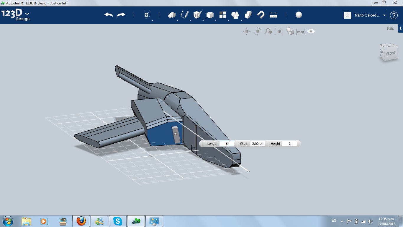
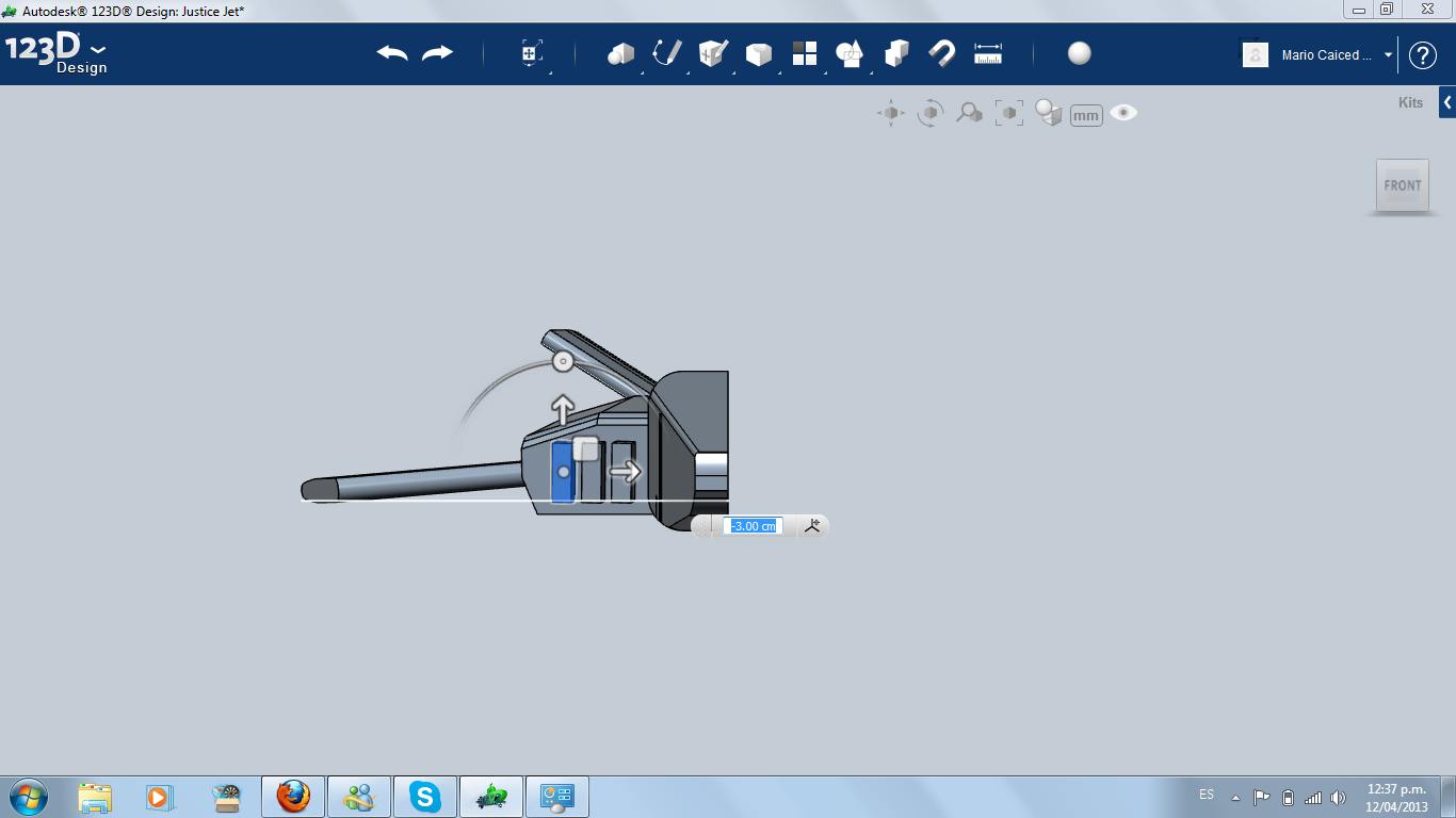
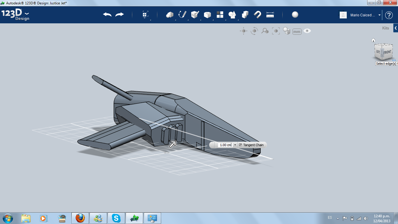
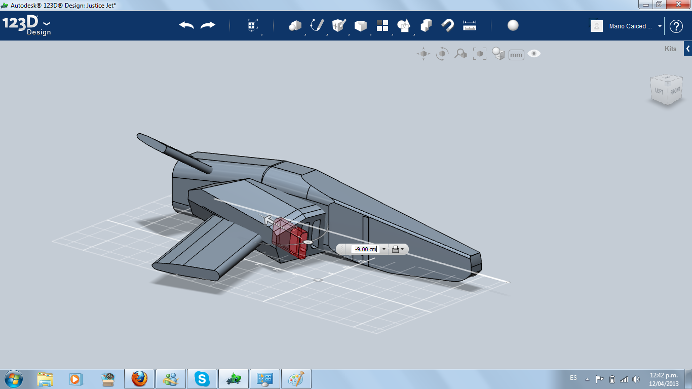
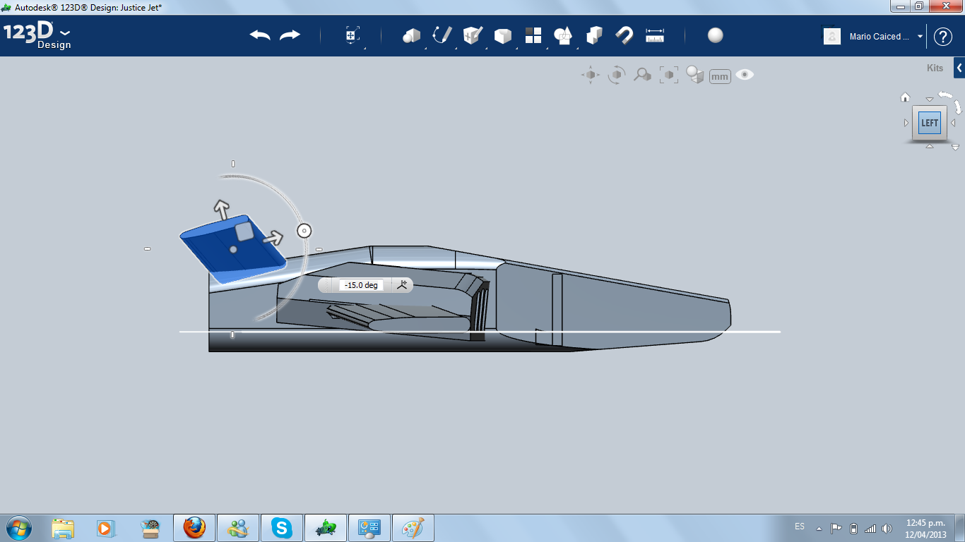
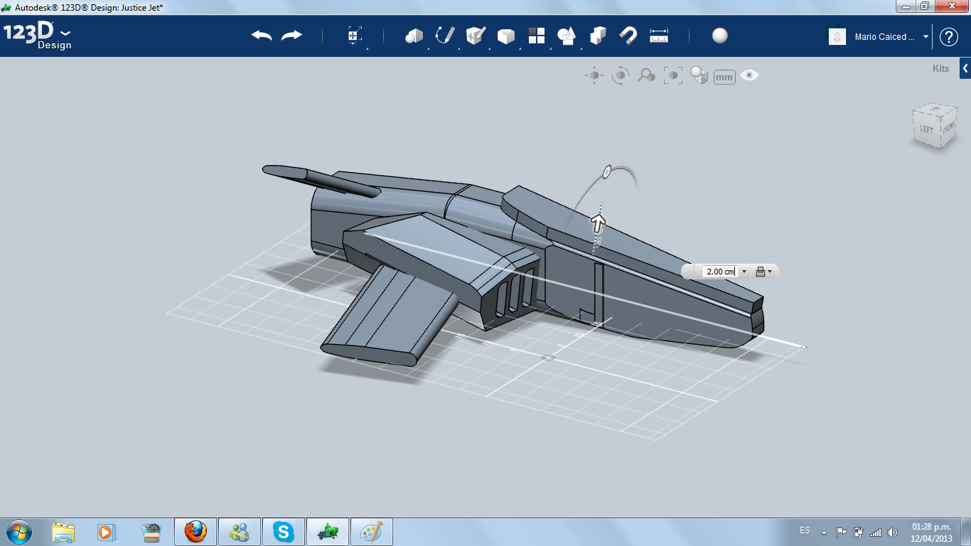
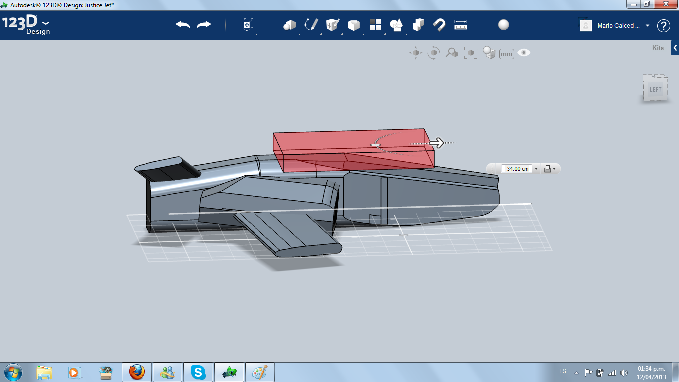
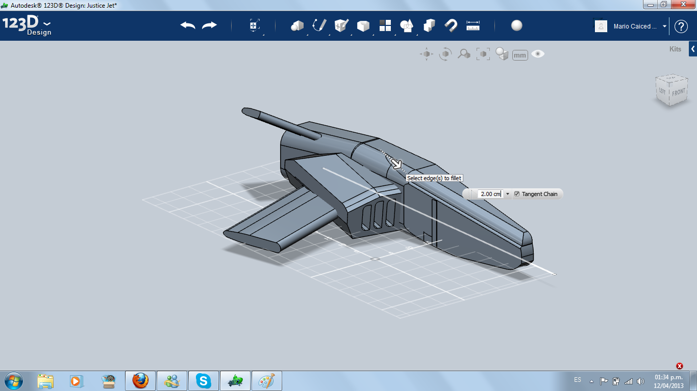
For the air intake aperture, I used three small filleted boxes and excluded.
Modifying Wing, Stabilizer and Creating the Turbine
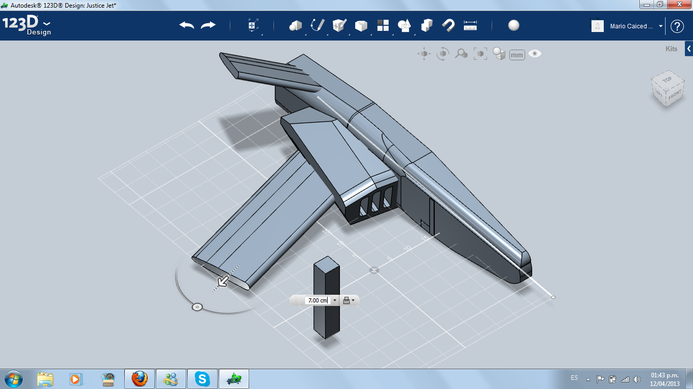
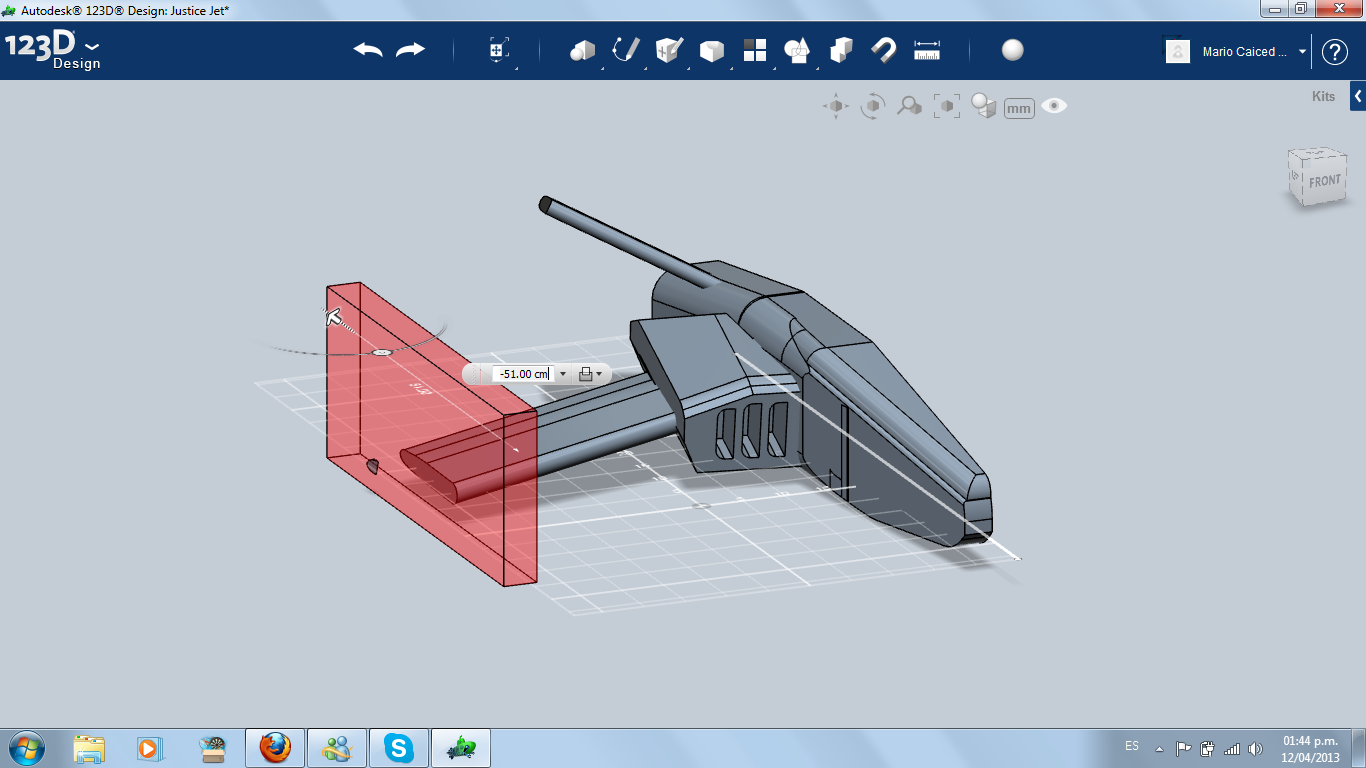
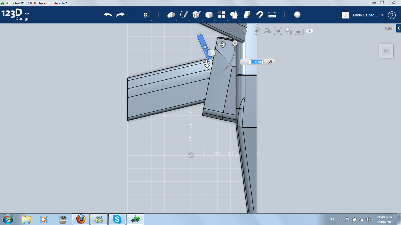
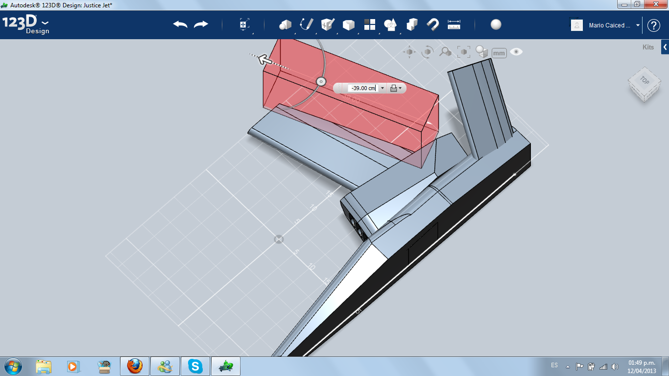
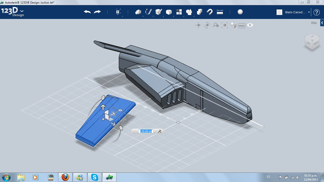
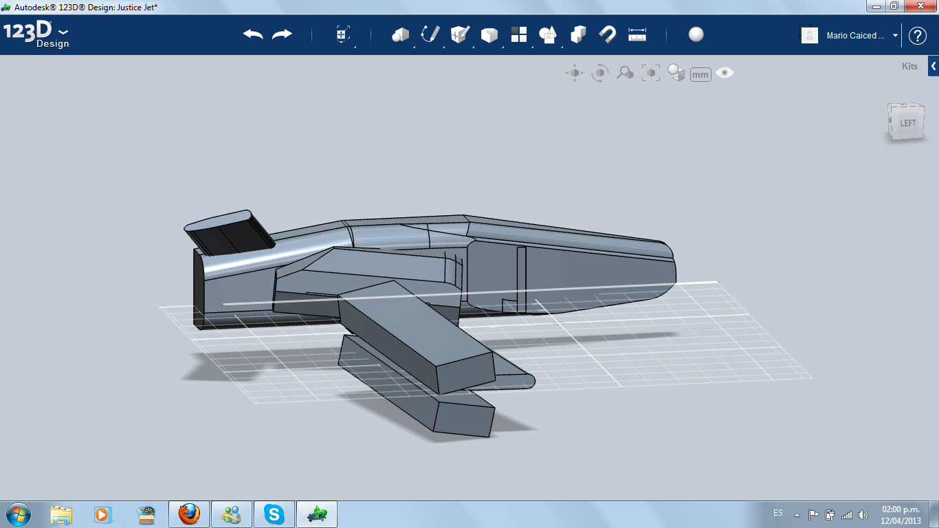
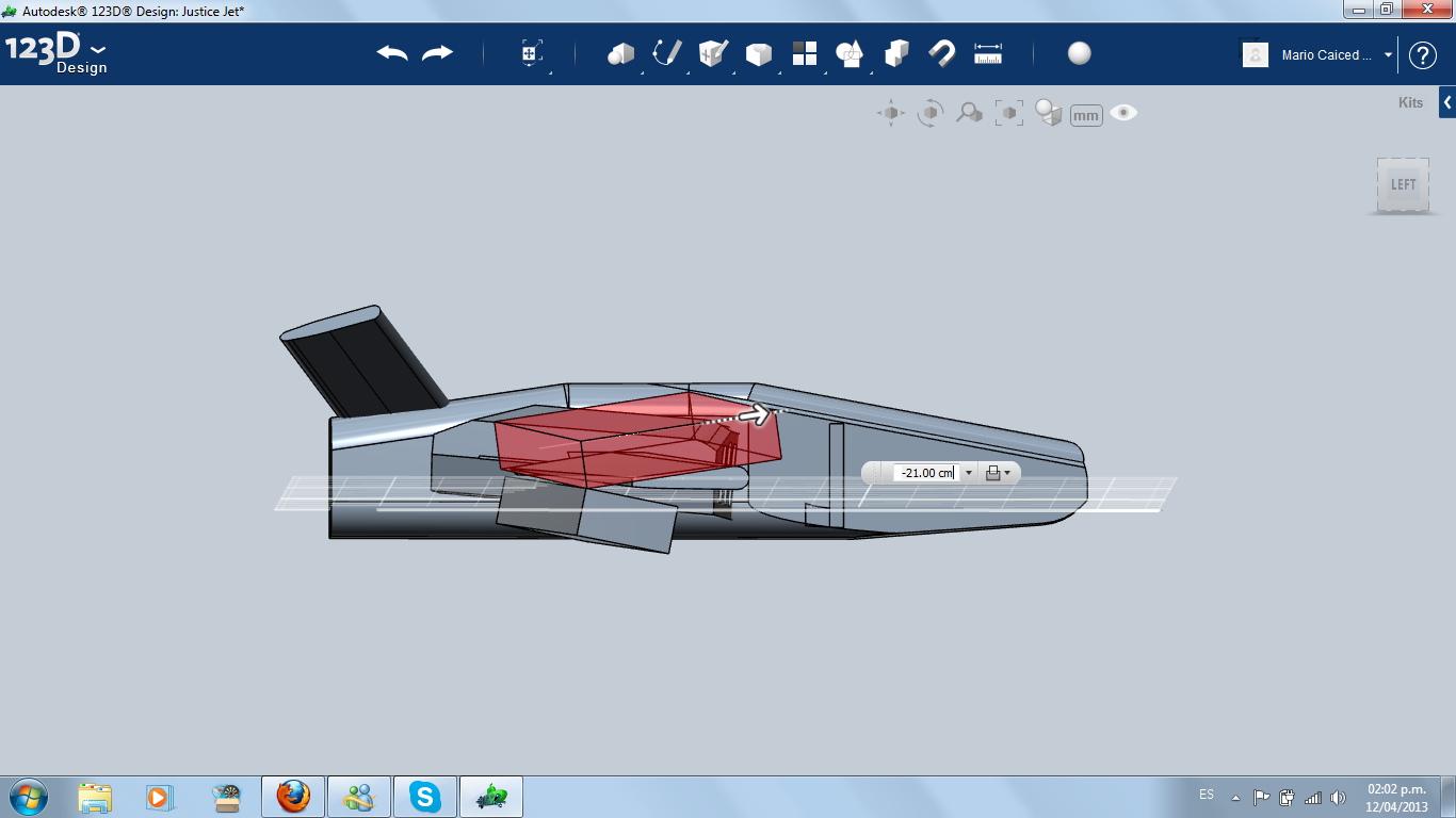
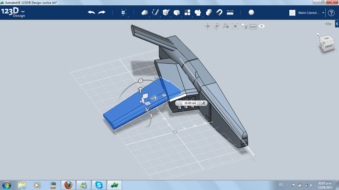
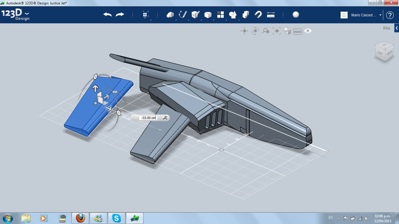
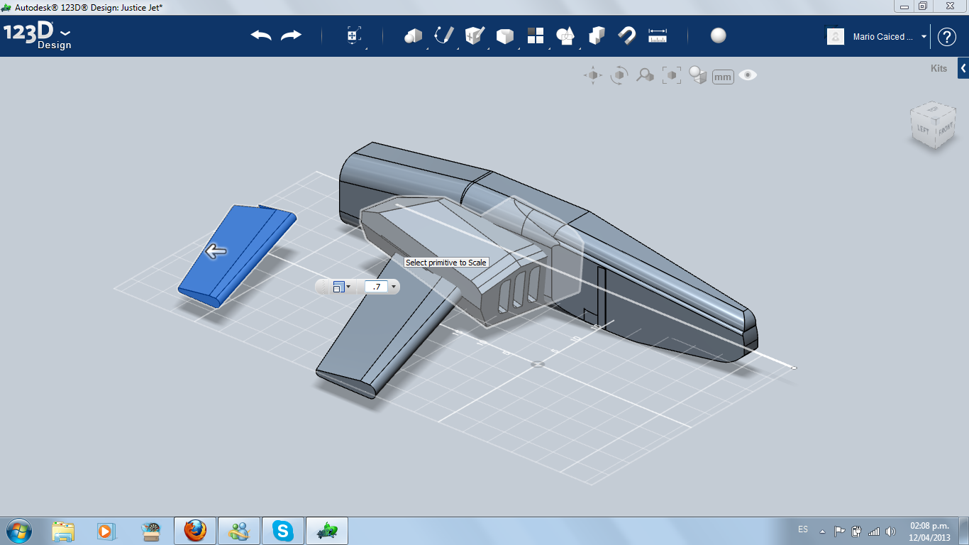
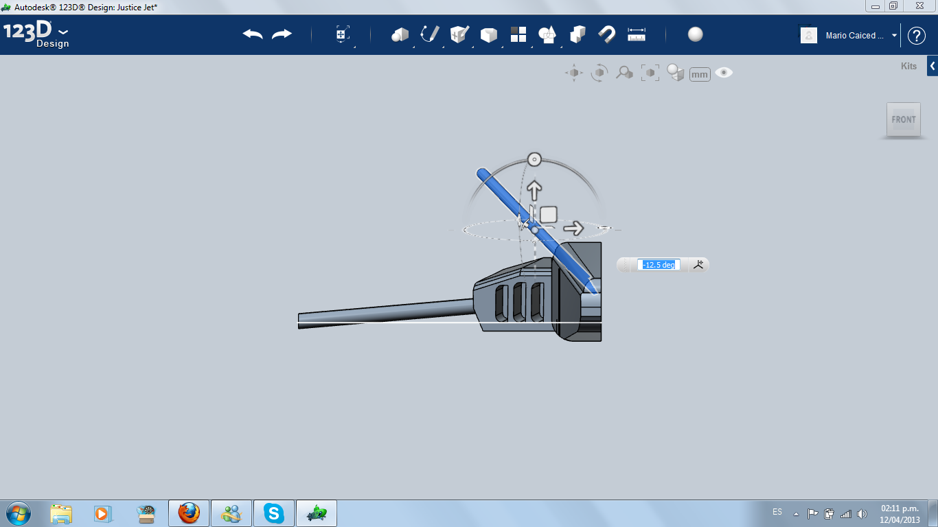
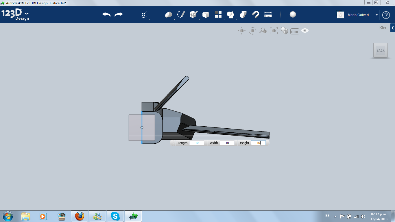
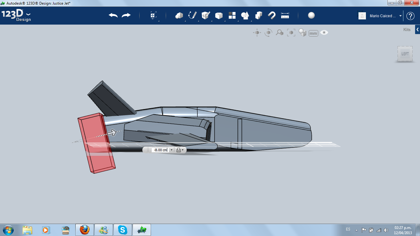
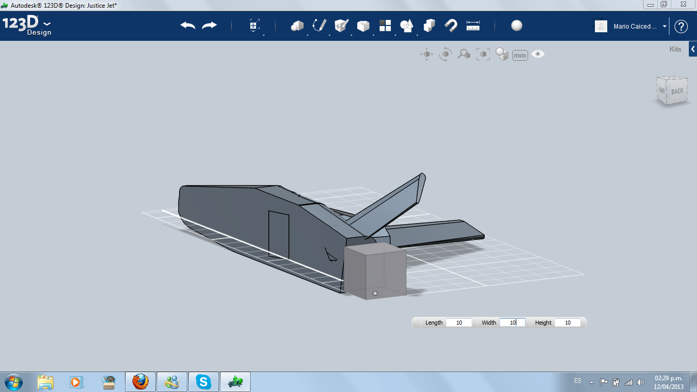
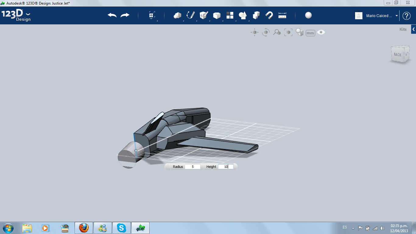
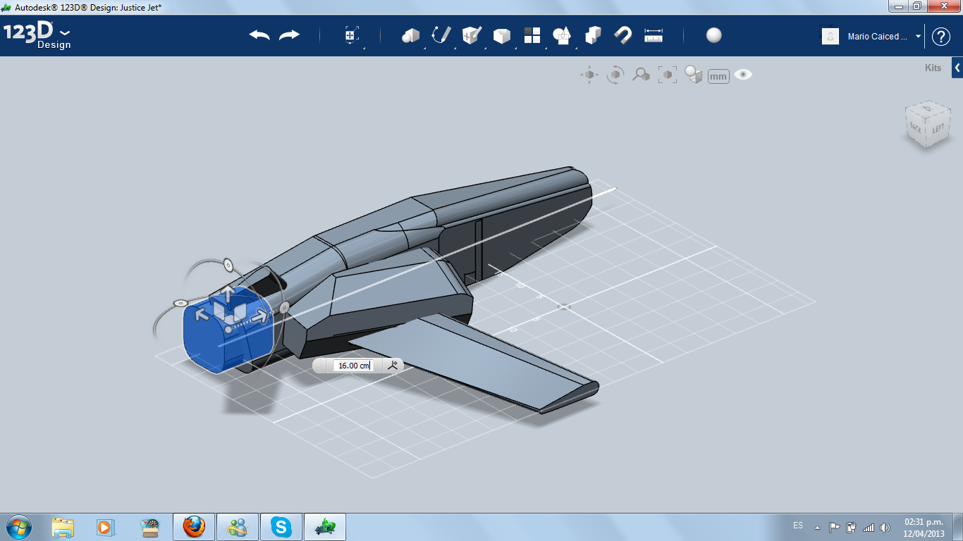
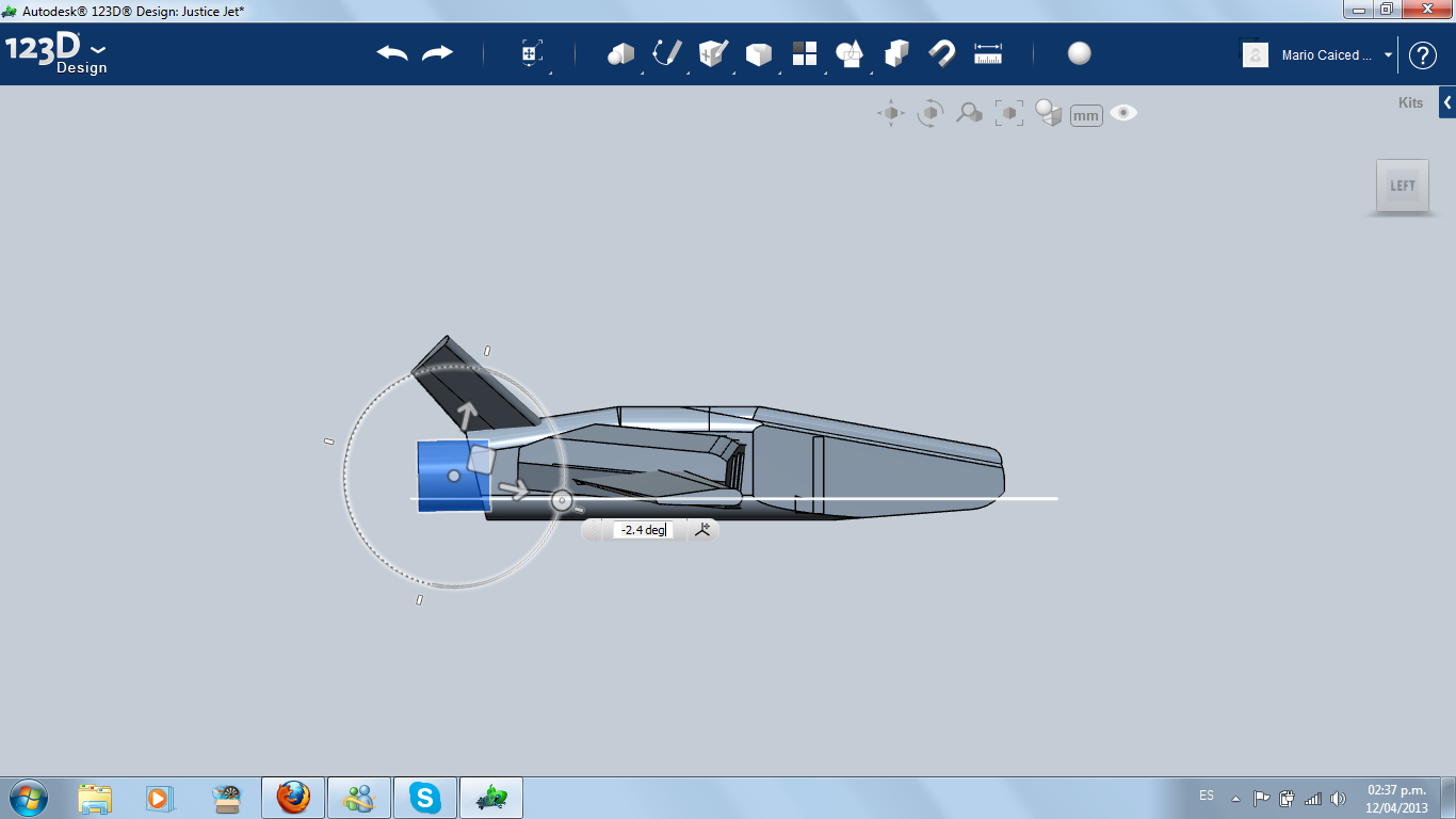
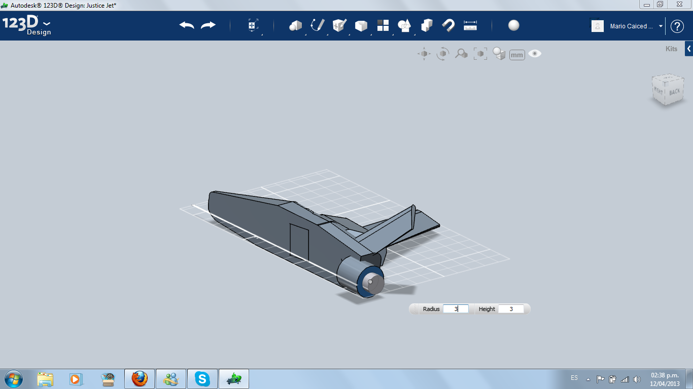
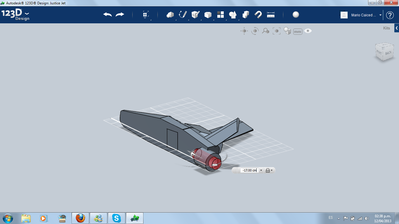
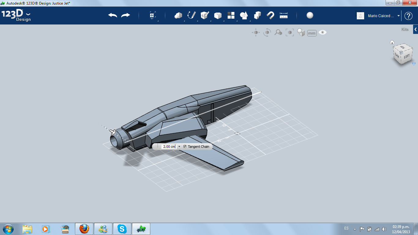
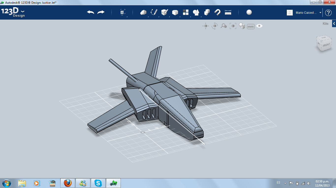
I decided to change the shape of the wing, cutting the end and reducing its length. Then, I copied it and made again the stabilizer, reducing scale.
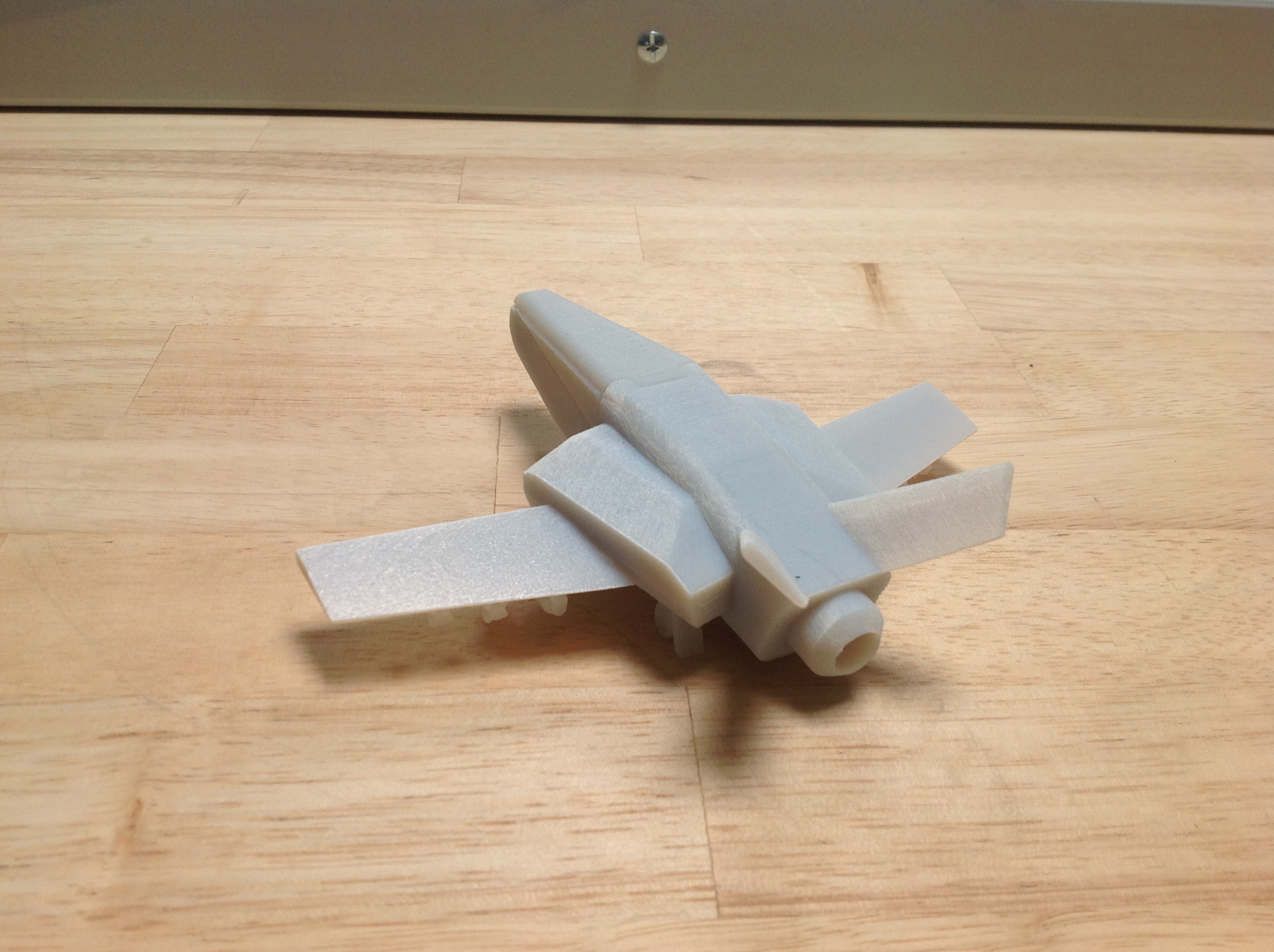
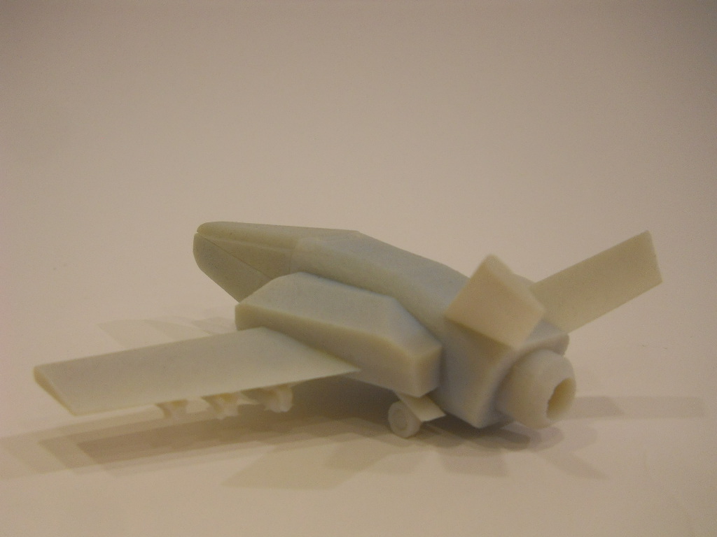
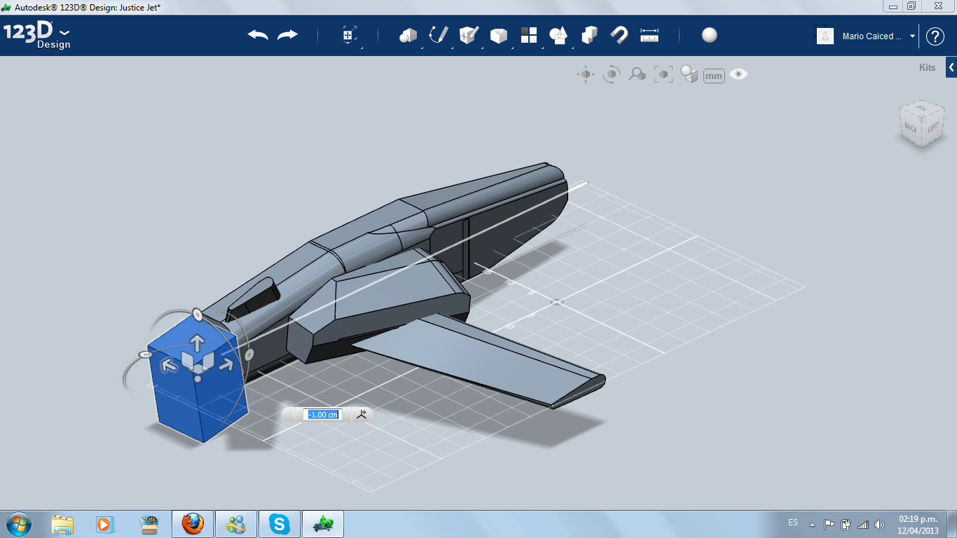
Then, I modified the back (again) and instaled a turbine using a cylinded. The center of the turbine was made extruding negatively another cylinder and then, chamfering.
Now it's time to verifying how is our jet. Use the sketch line of the beginning and then, use the mirror pattern.
Then, I modified the back (again) and instaled a turbine using a cylinded. The center of the turbine was made extruding negatively another cylinder and then, chamfering.
Now it's time to verifying how is our jet. Use the sketch line of the beginning and then, use the mirror pattern.
The Cockpit
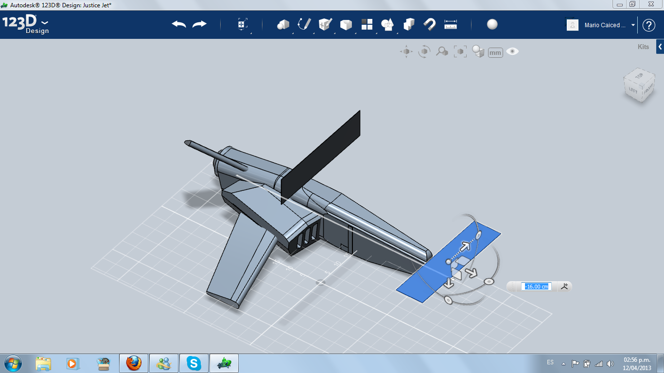
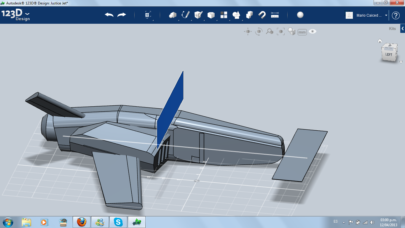
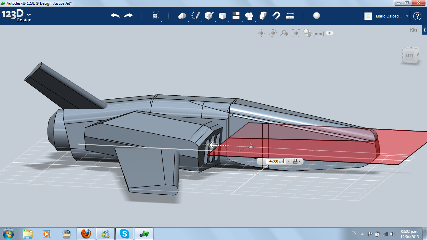
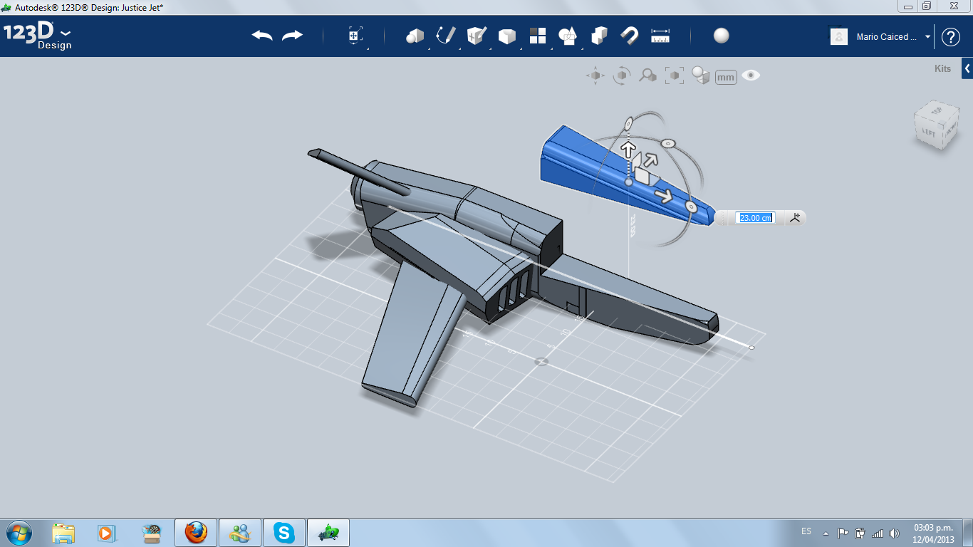
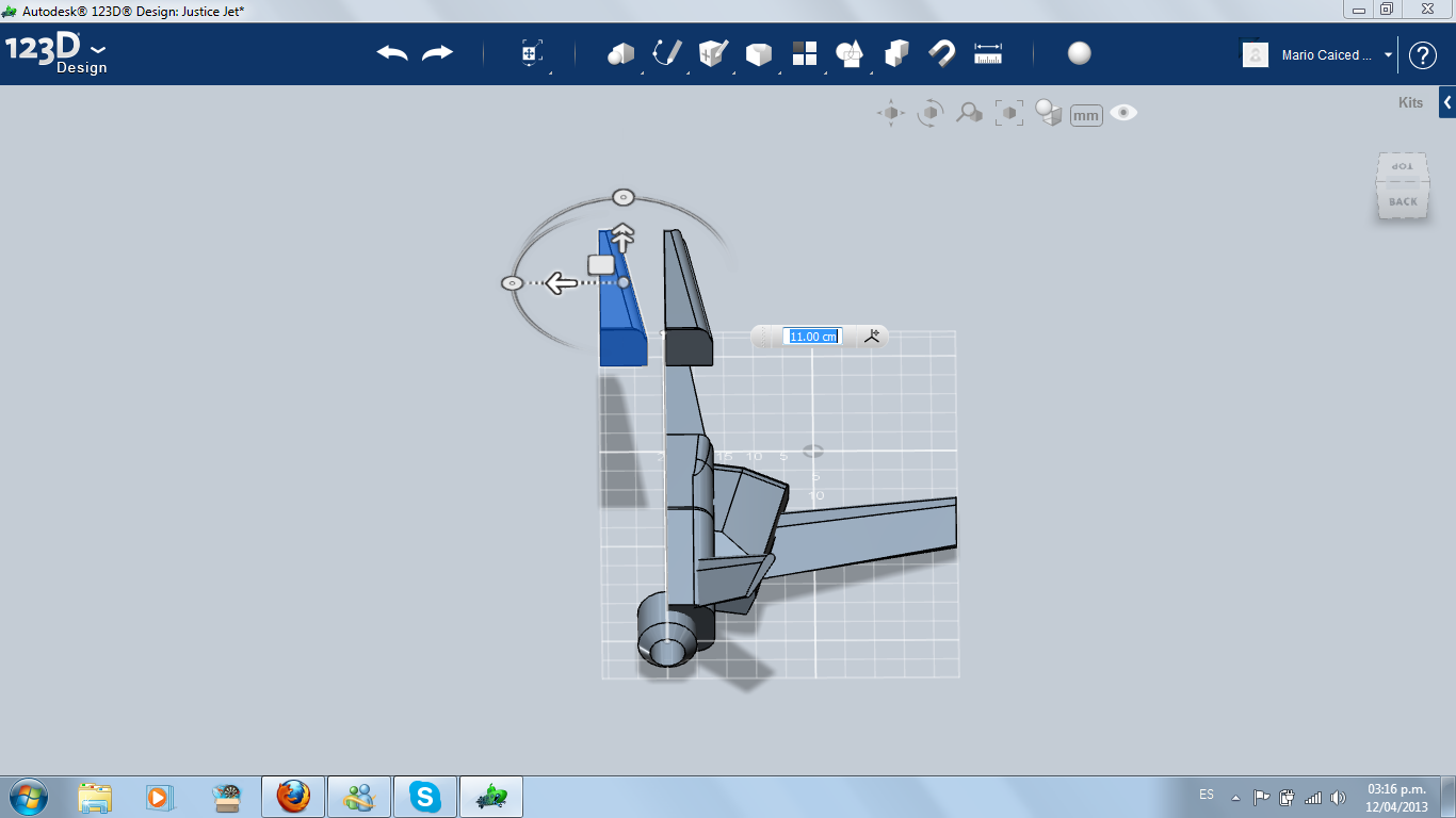
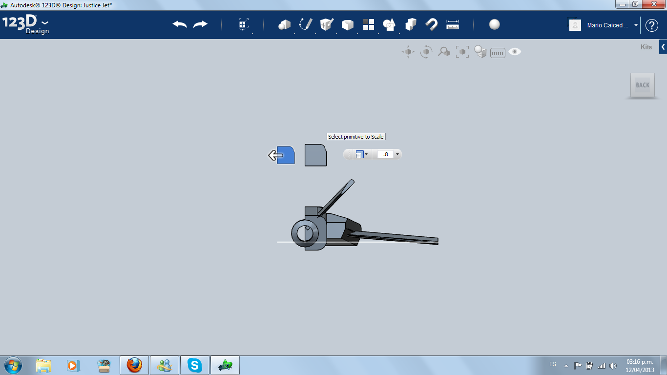
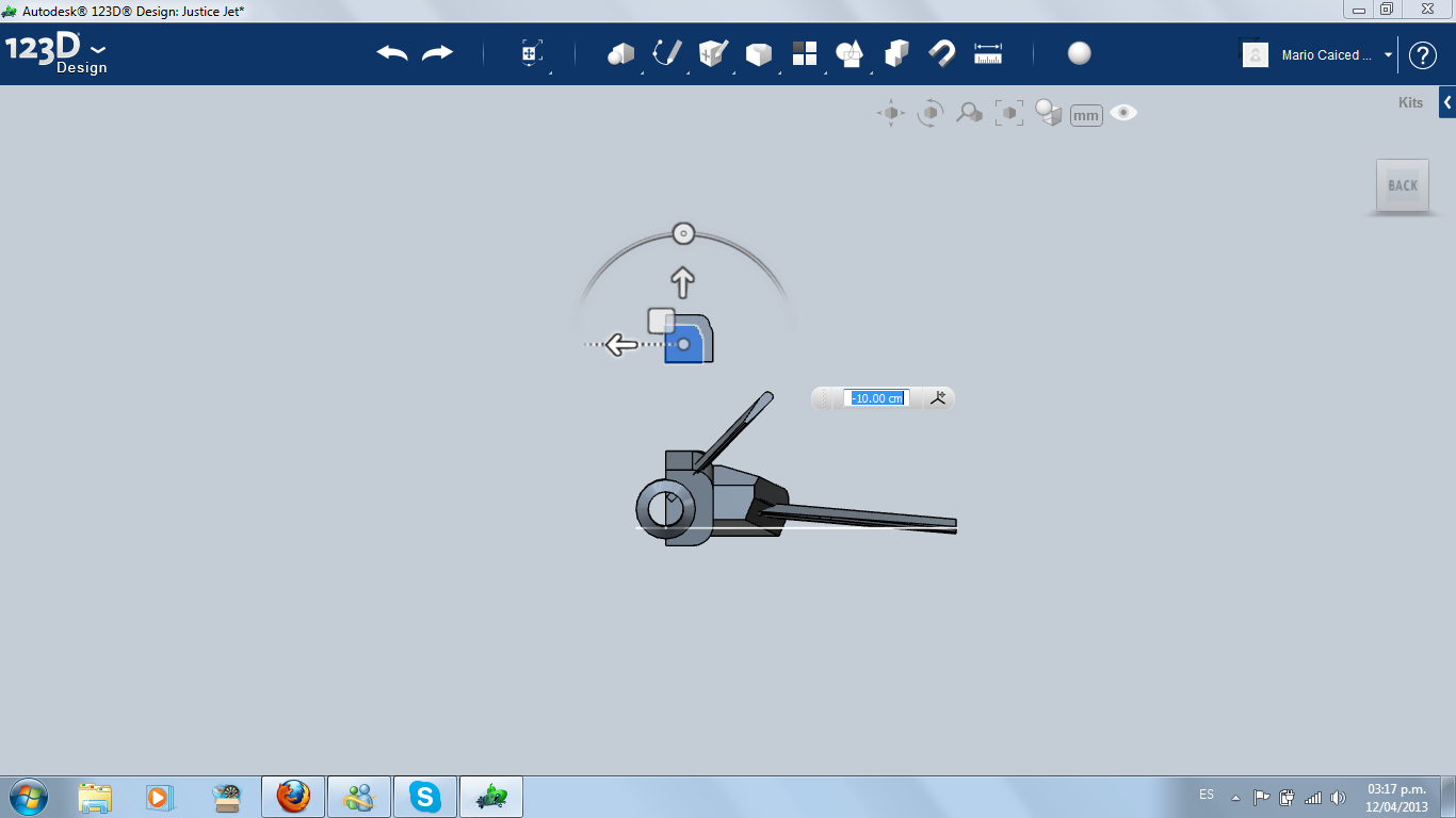
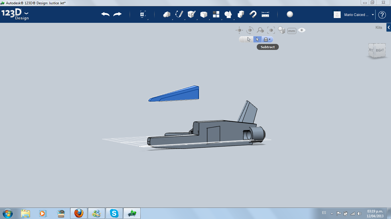
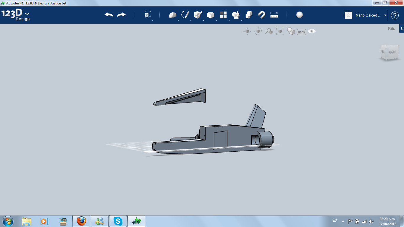
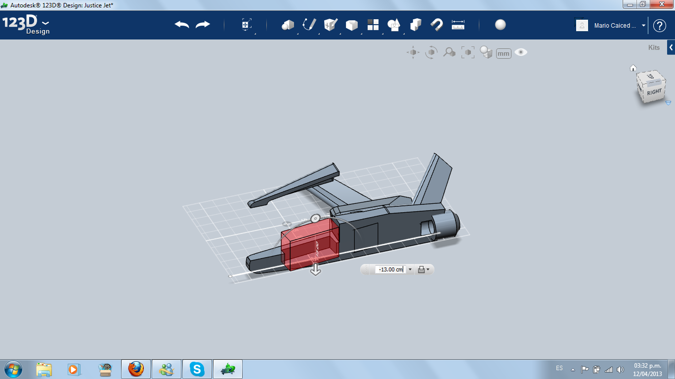
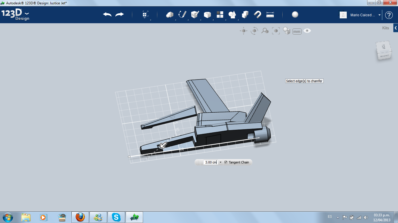
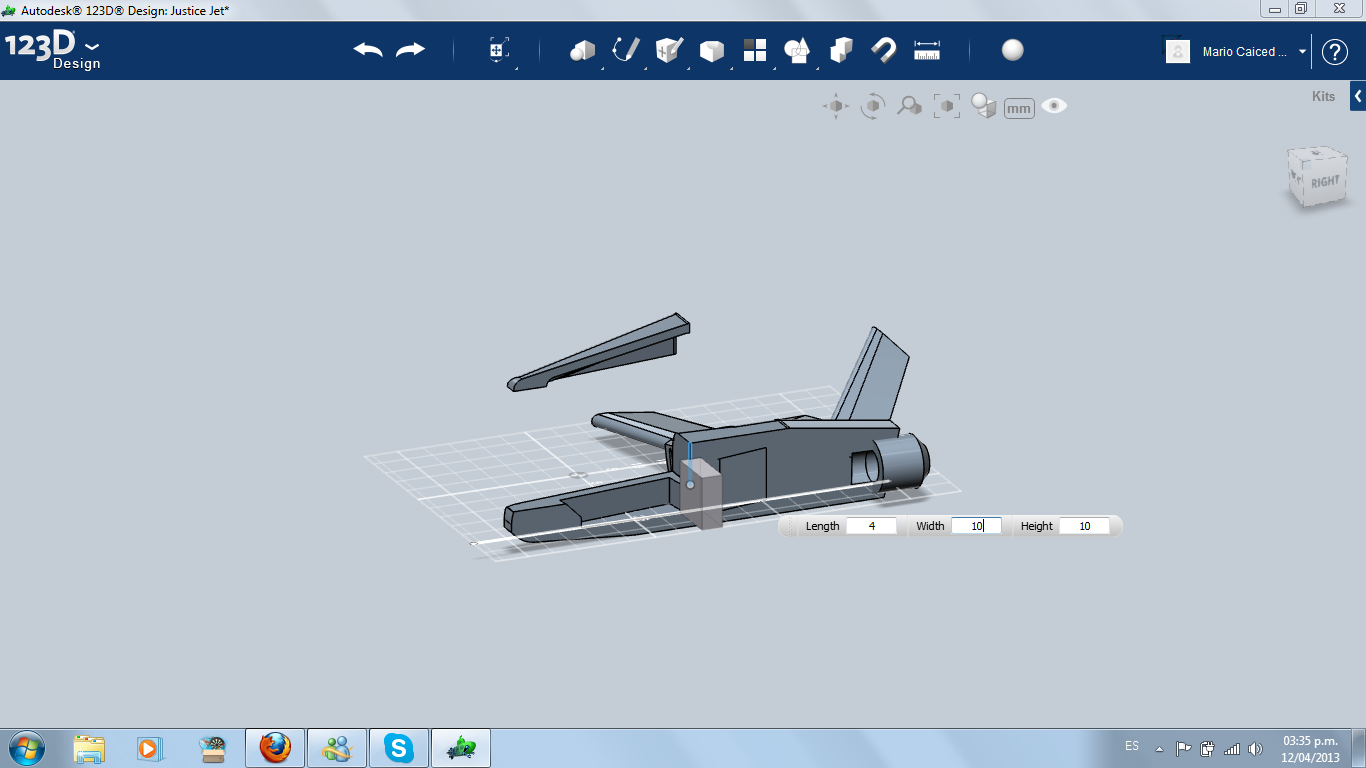
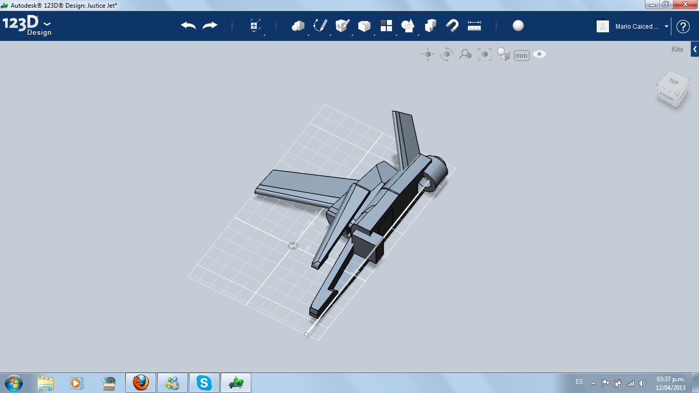
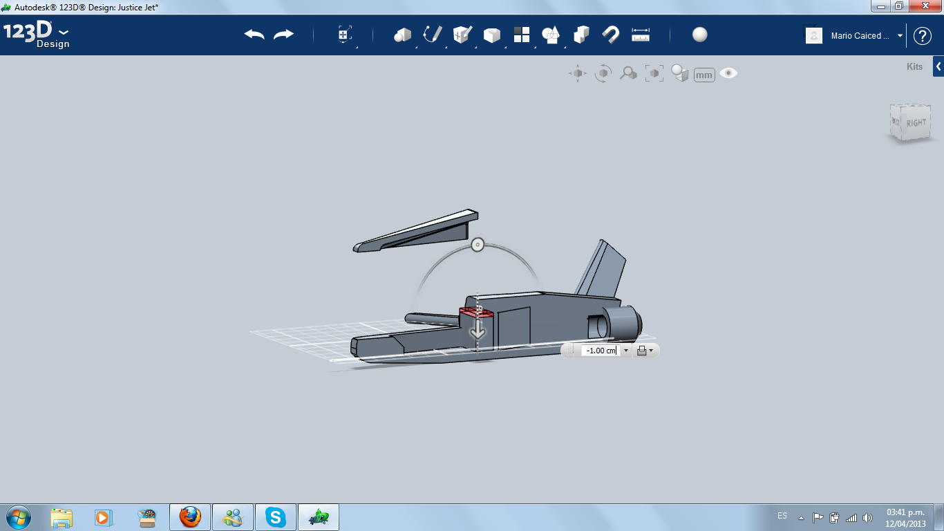
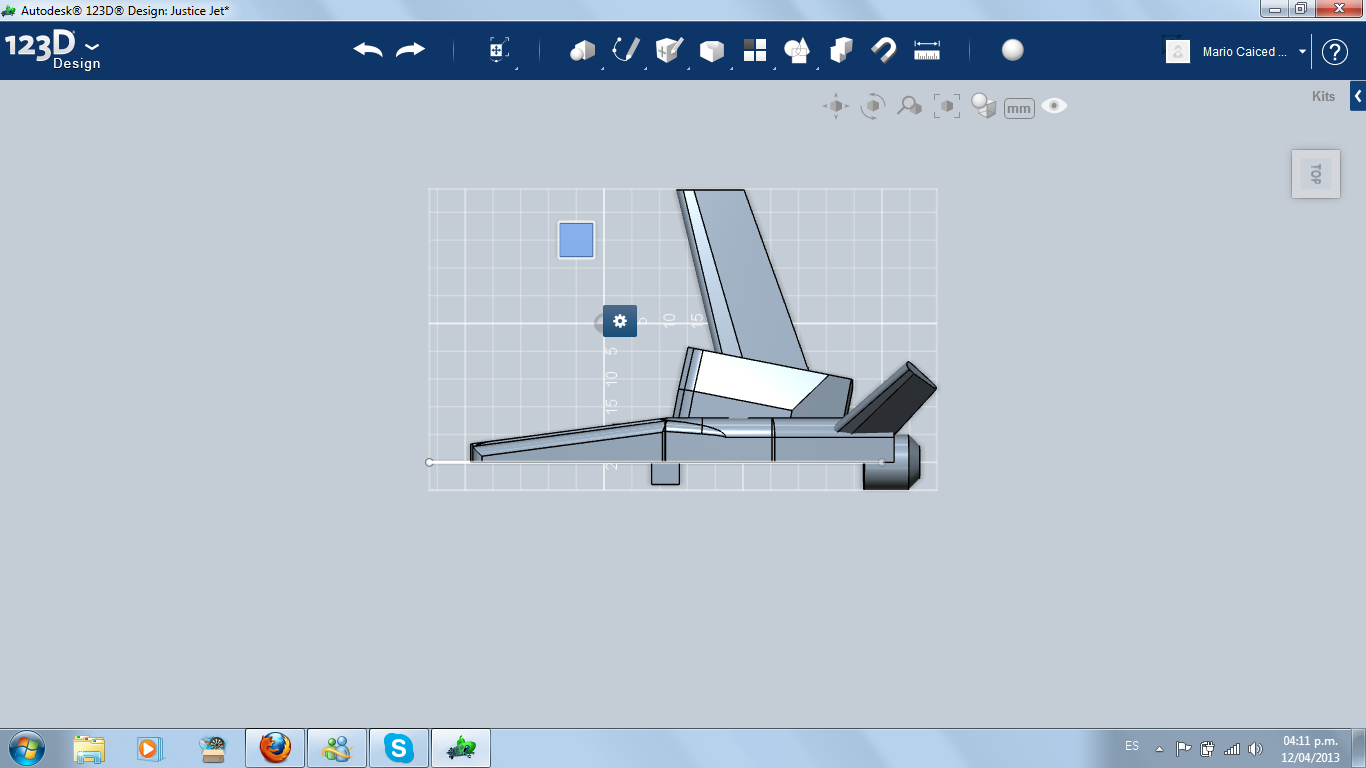
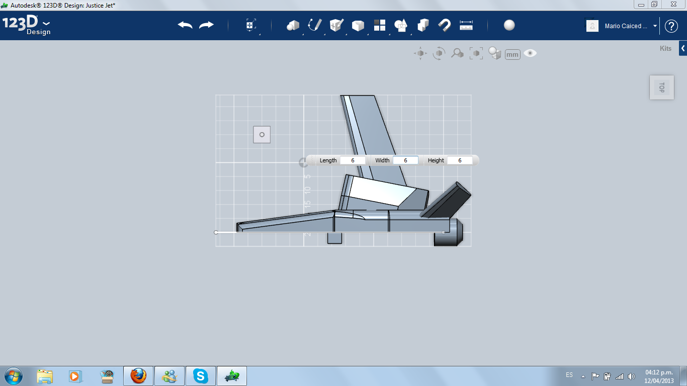
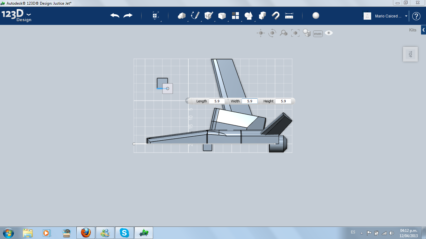
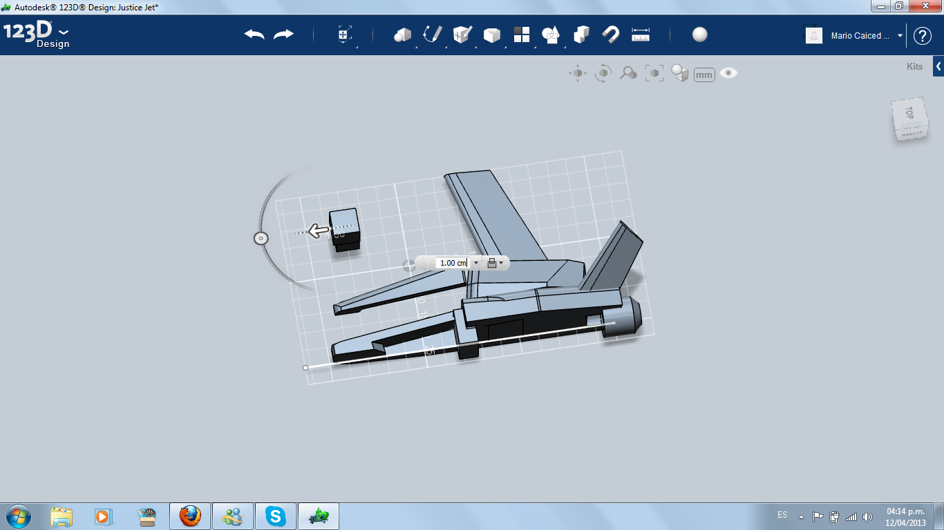
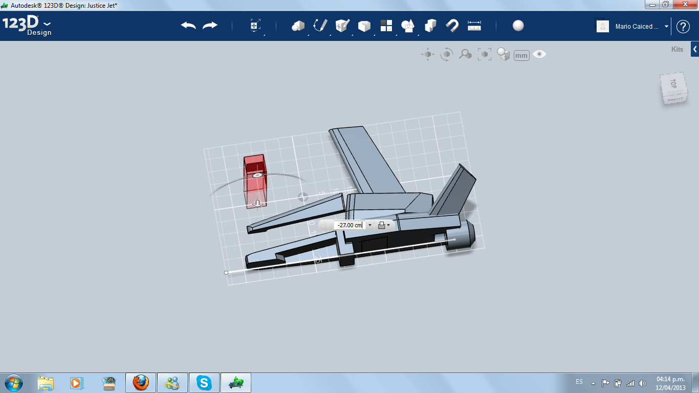
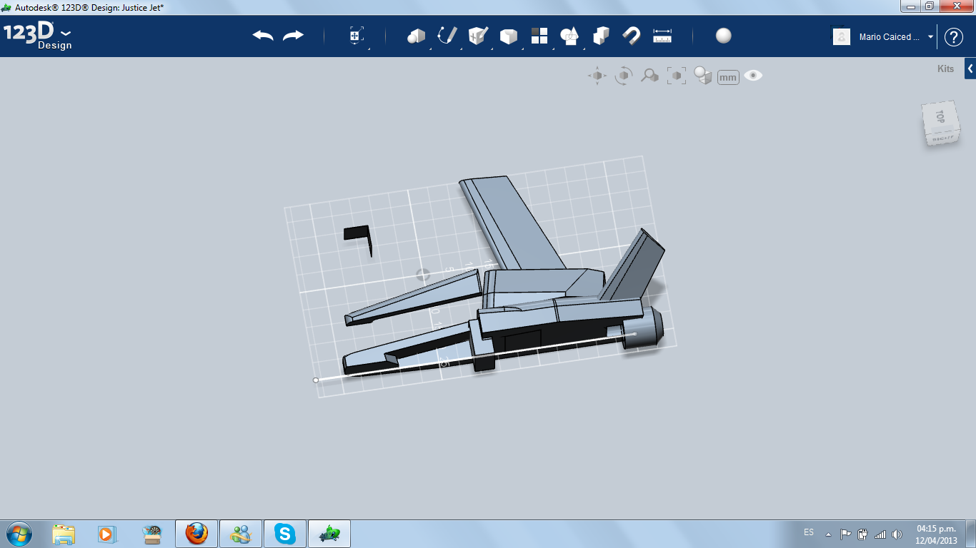
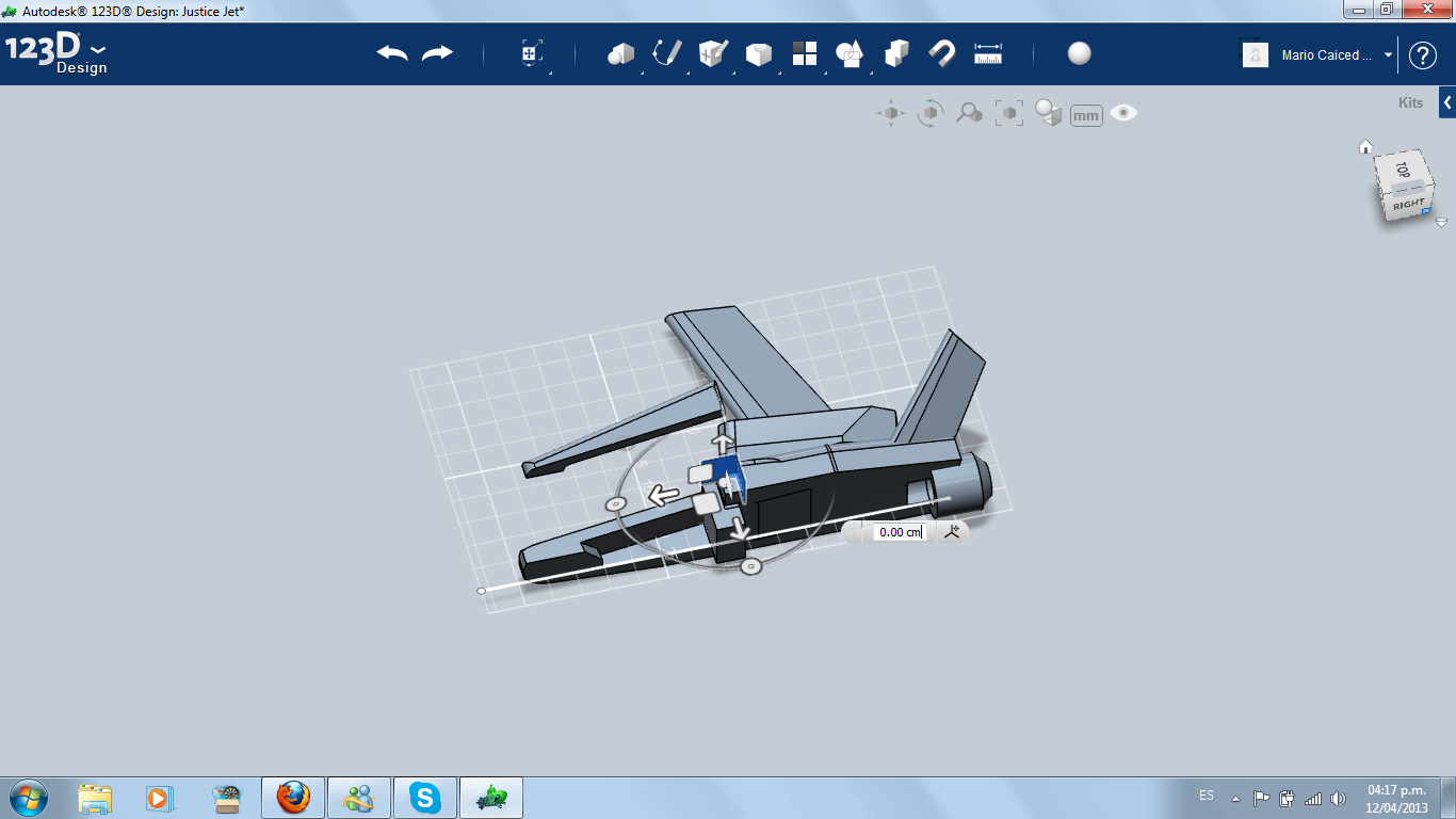
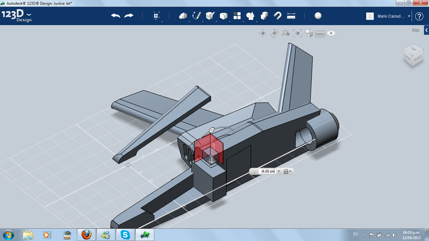
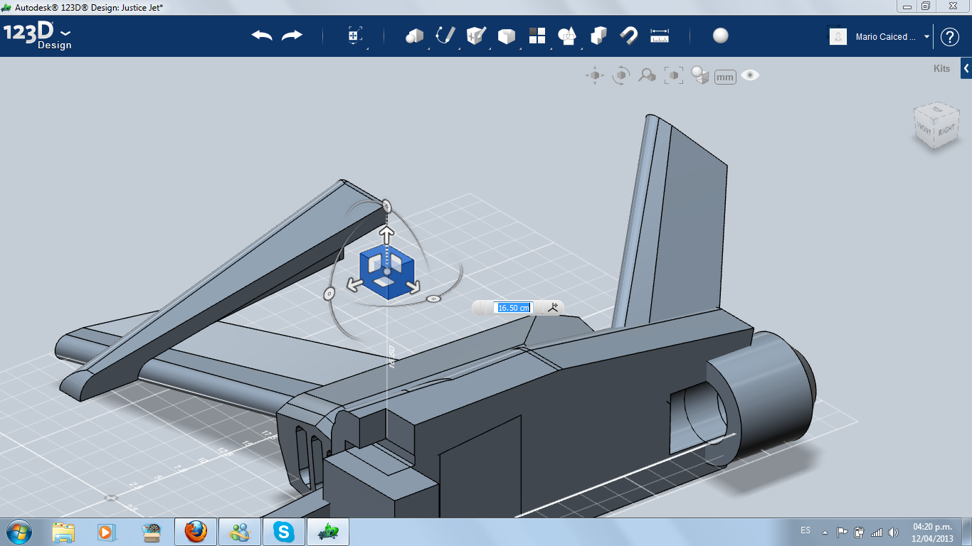
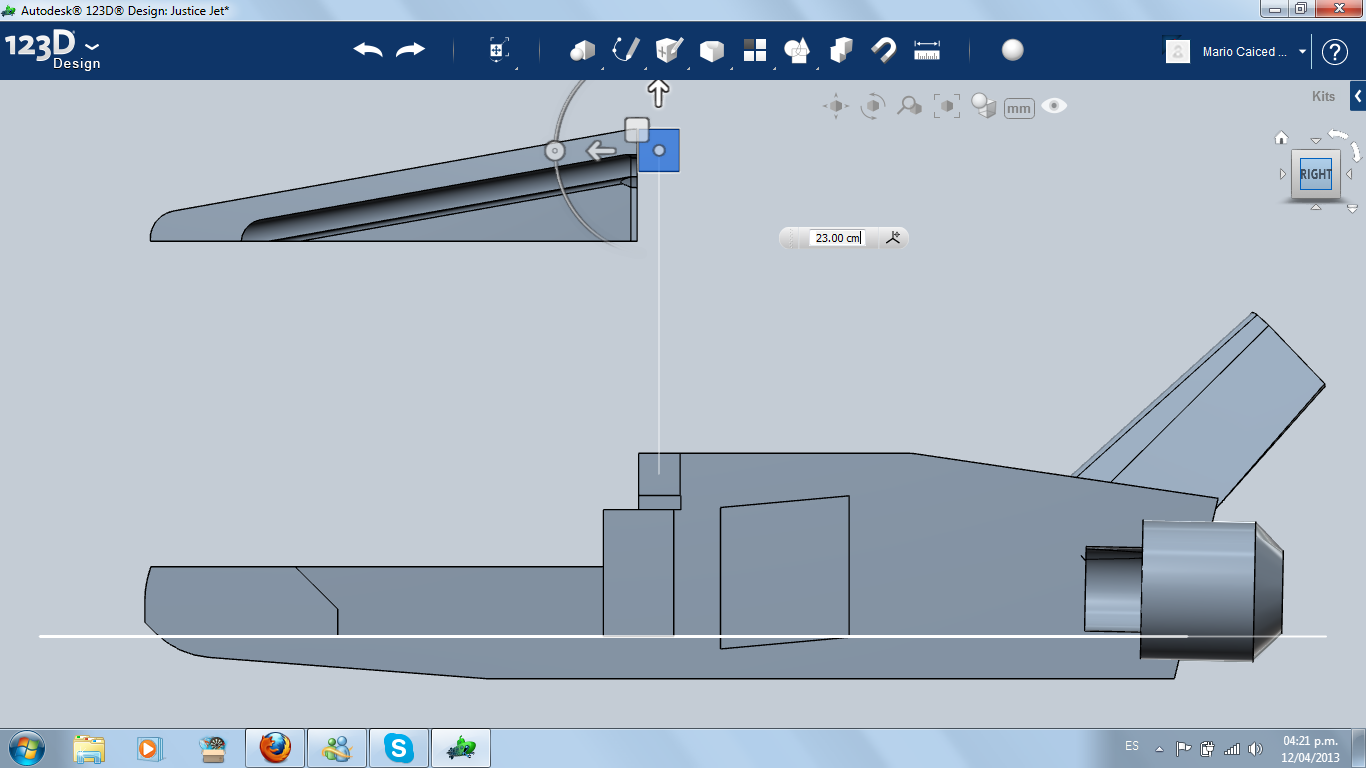
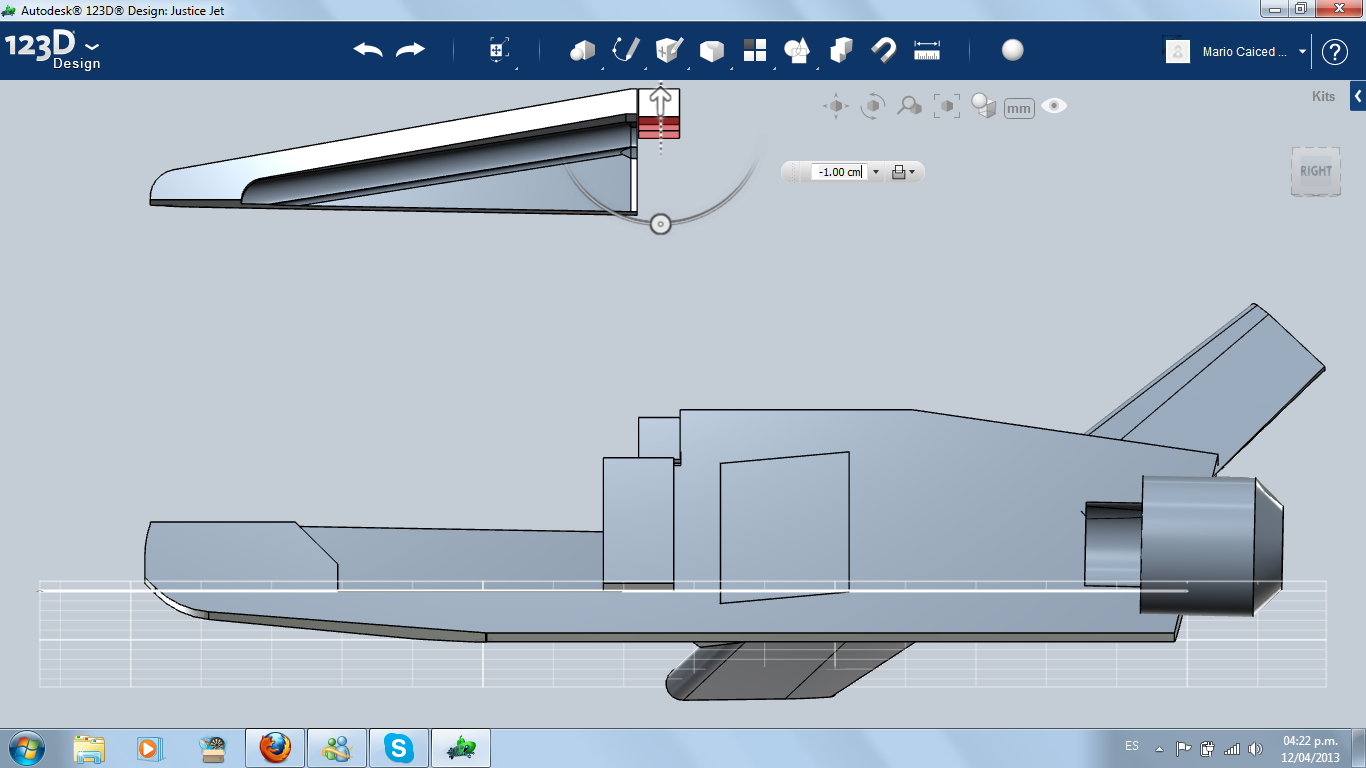
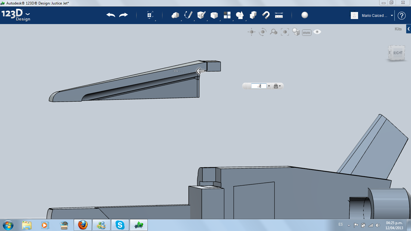
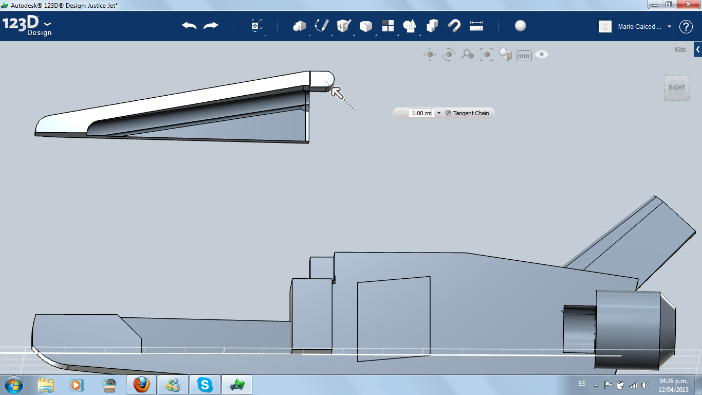
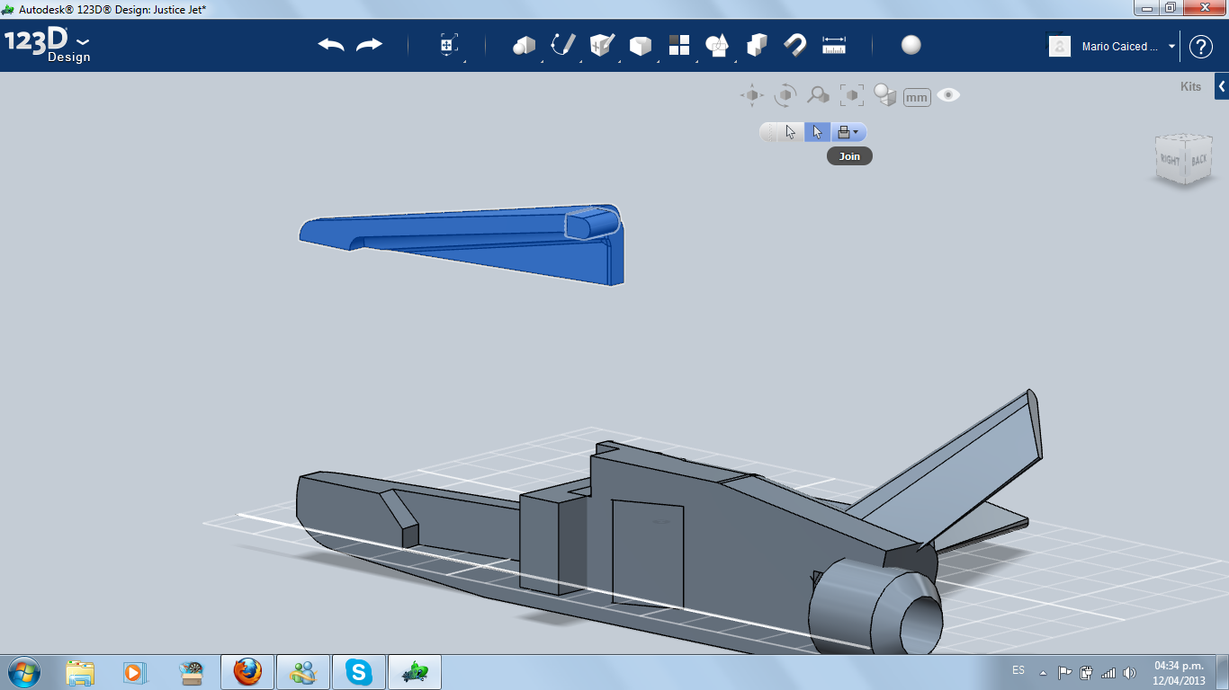
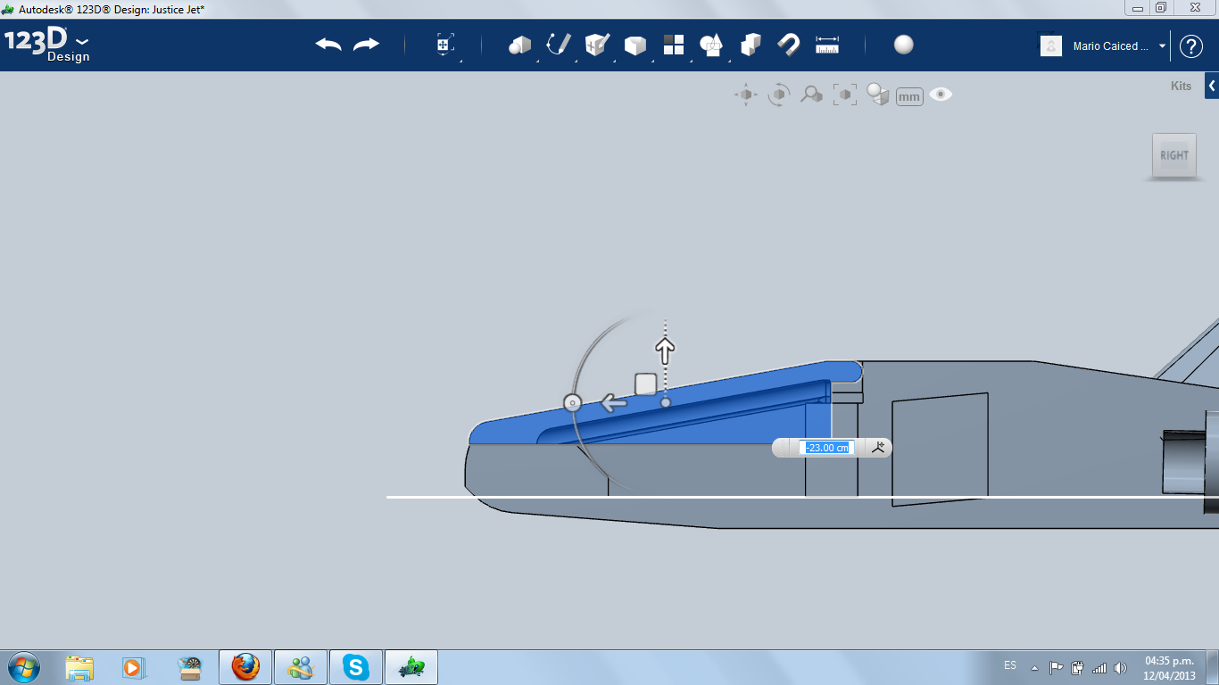
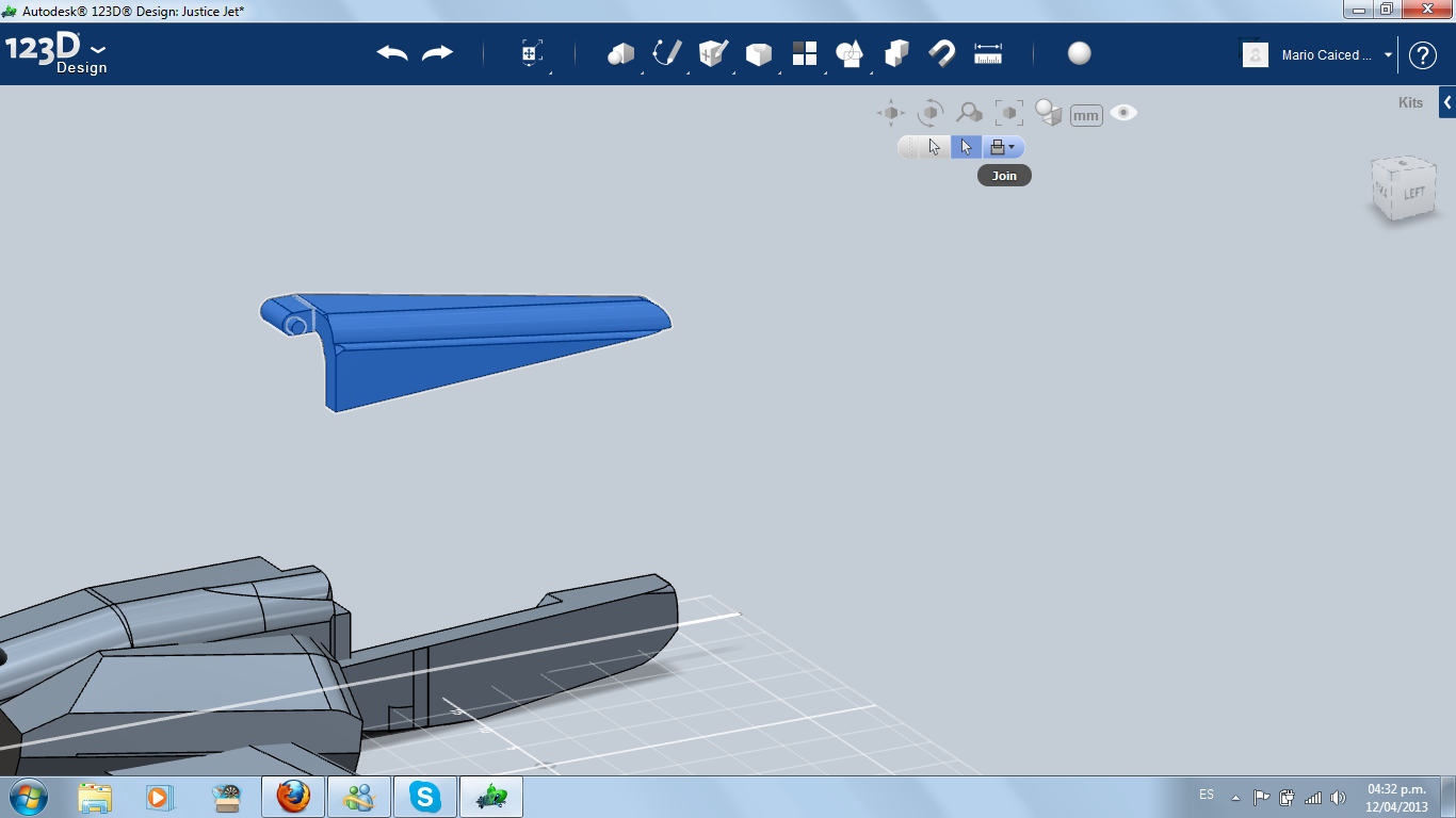
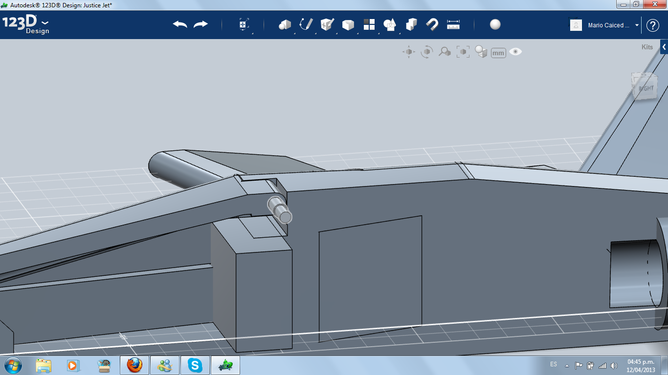
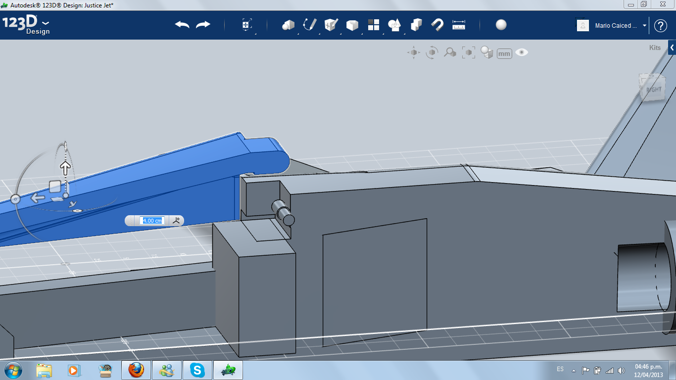
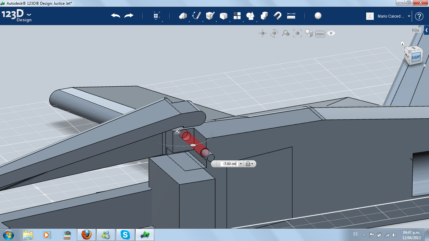
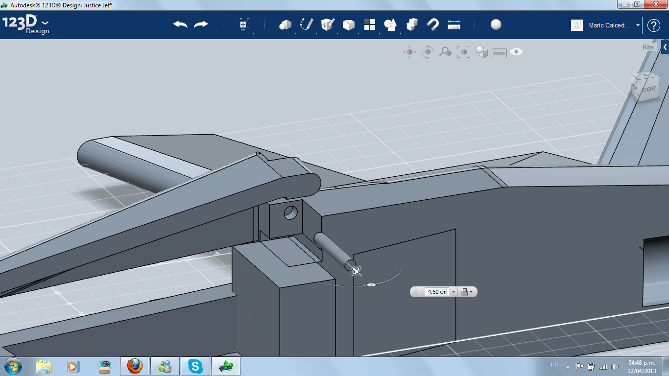
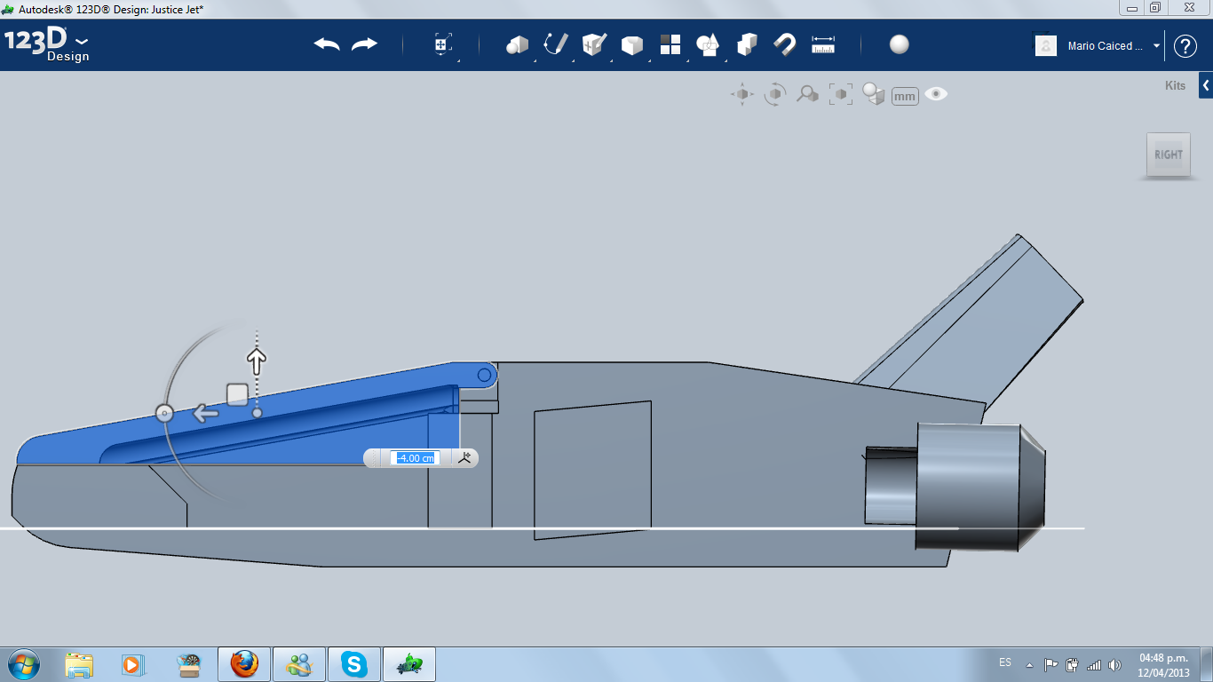
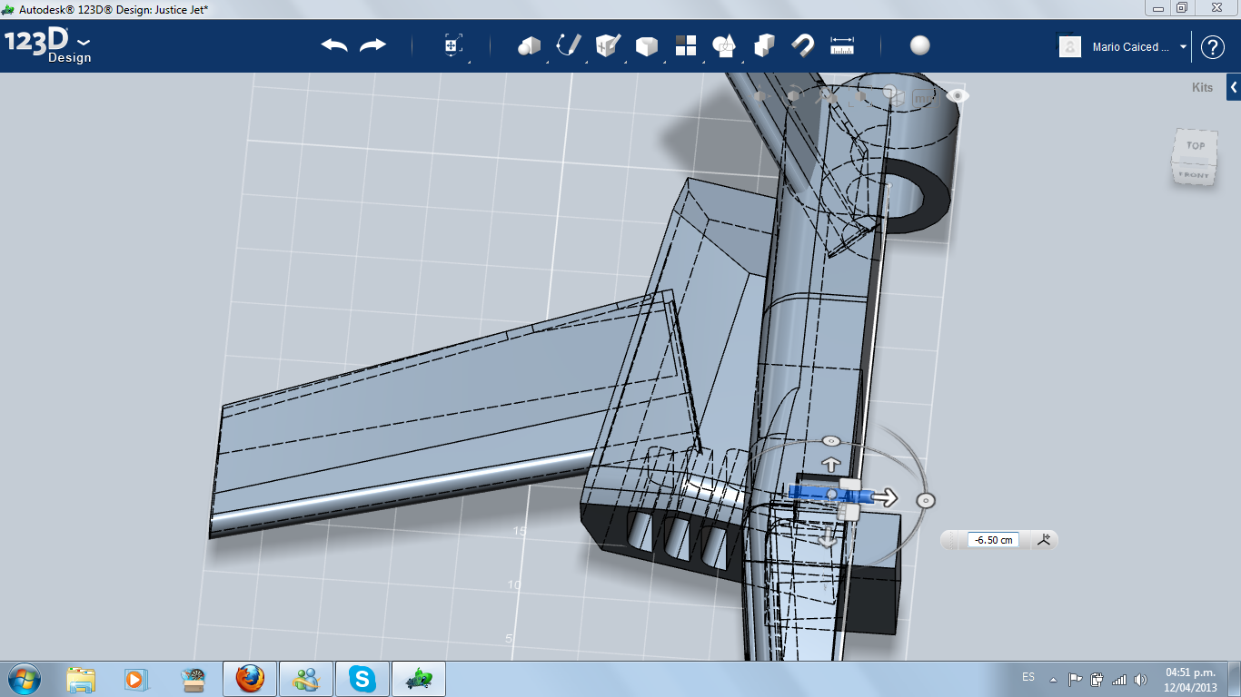
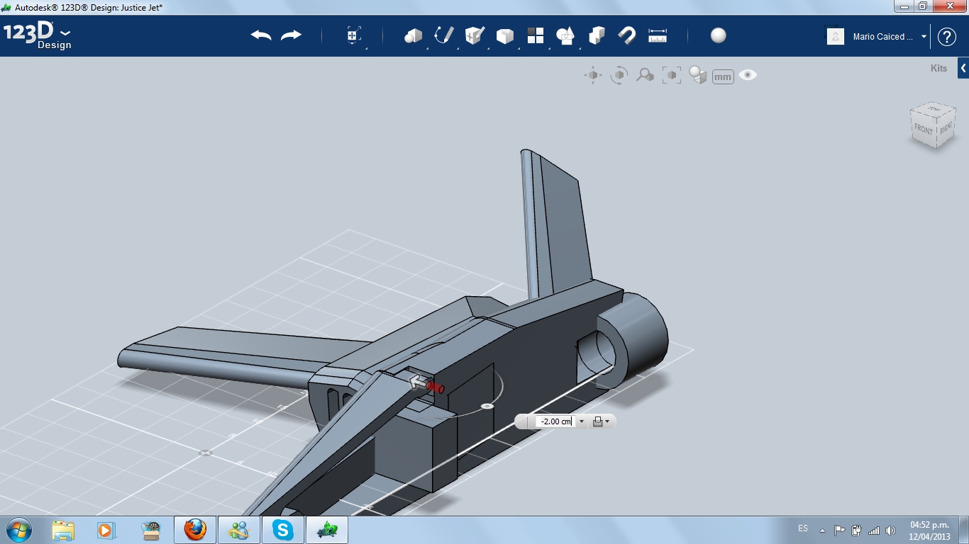
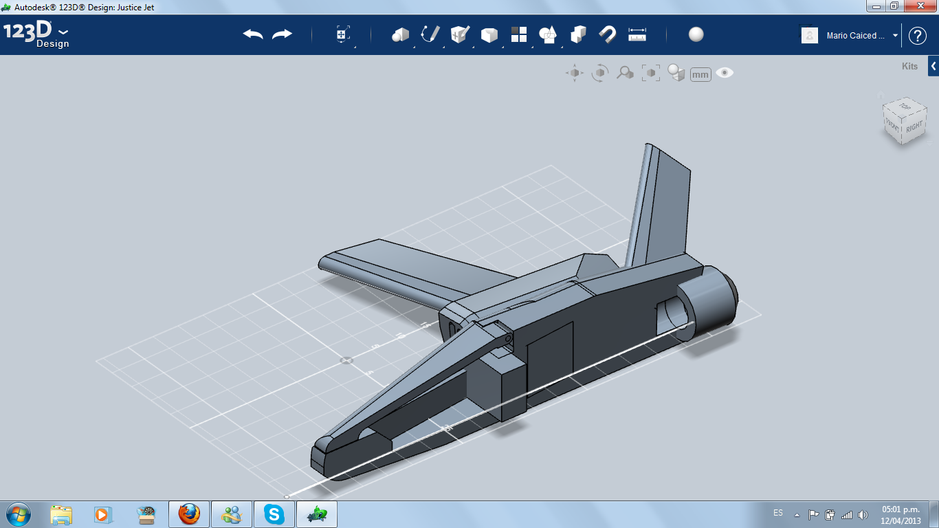
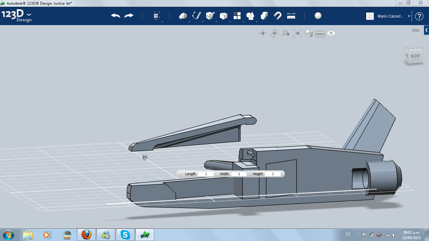
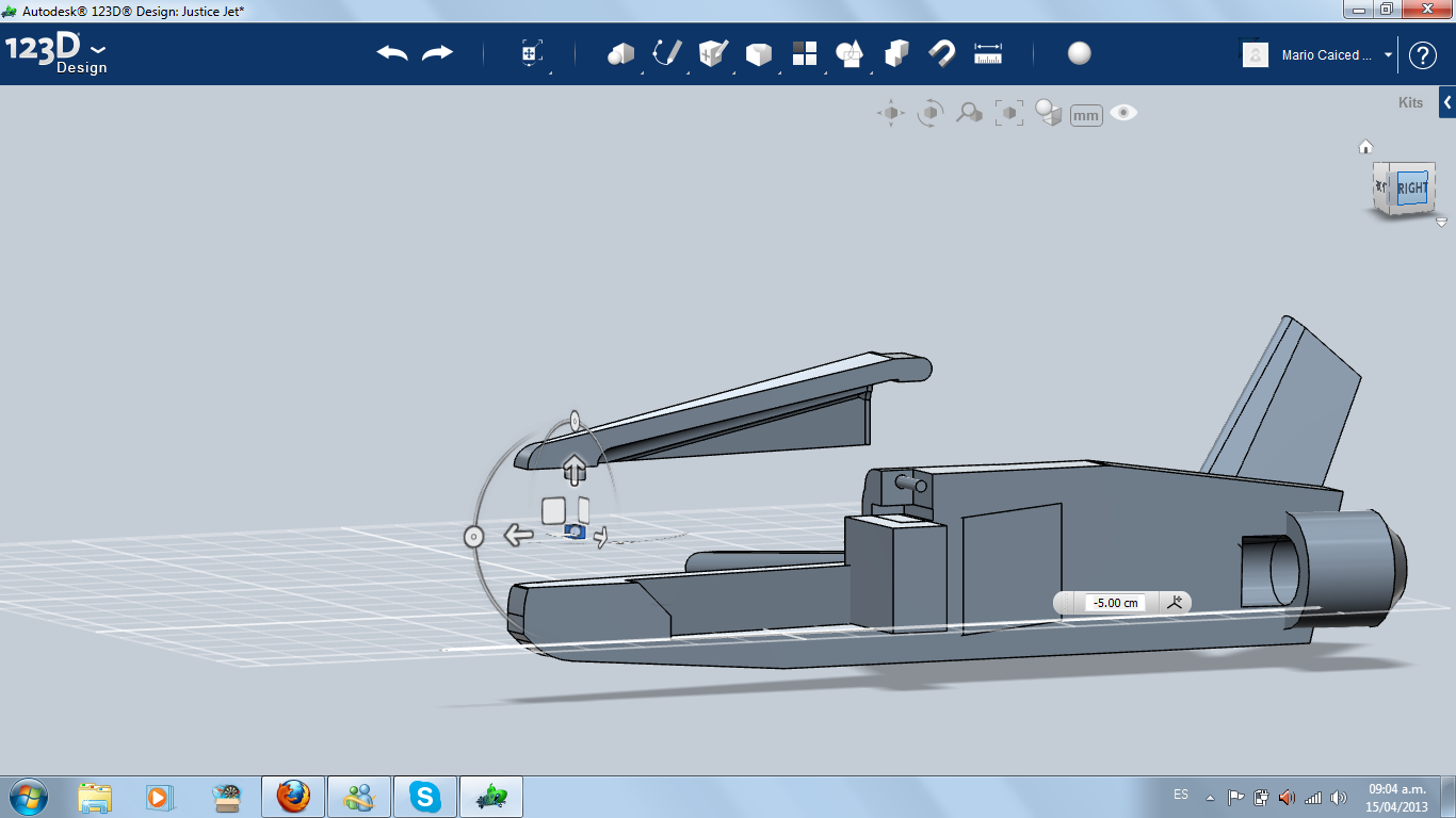
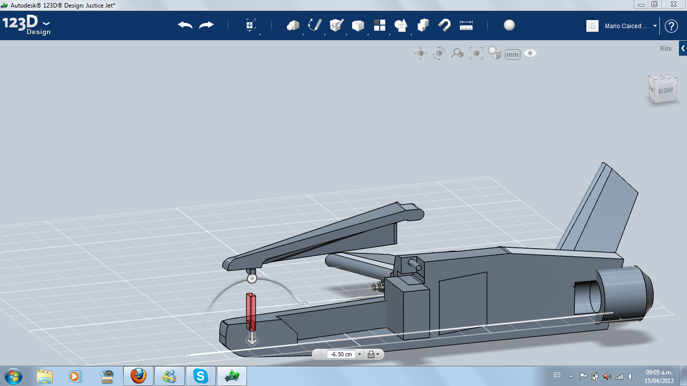
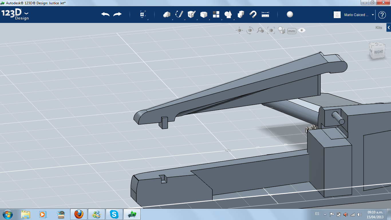
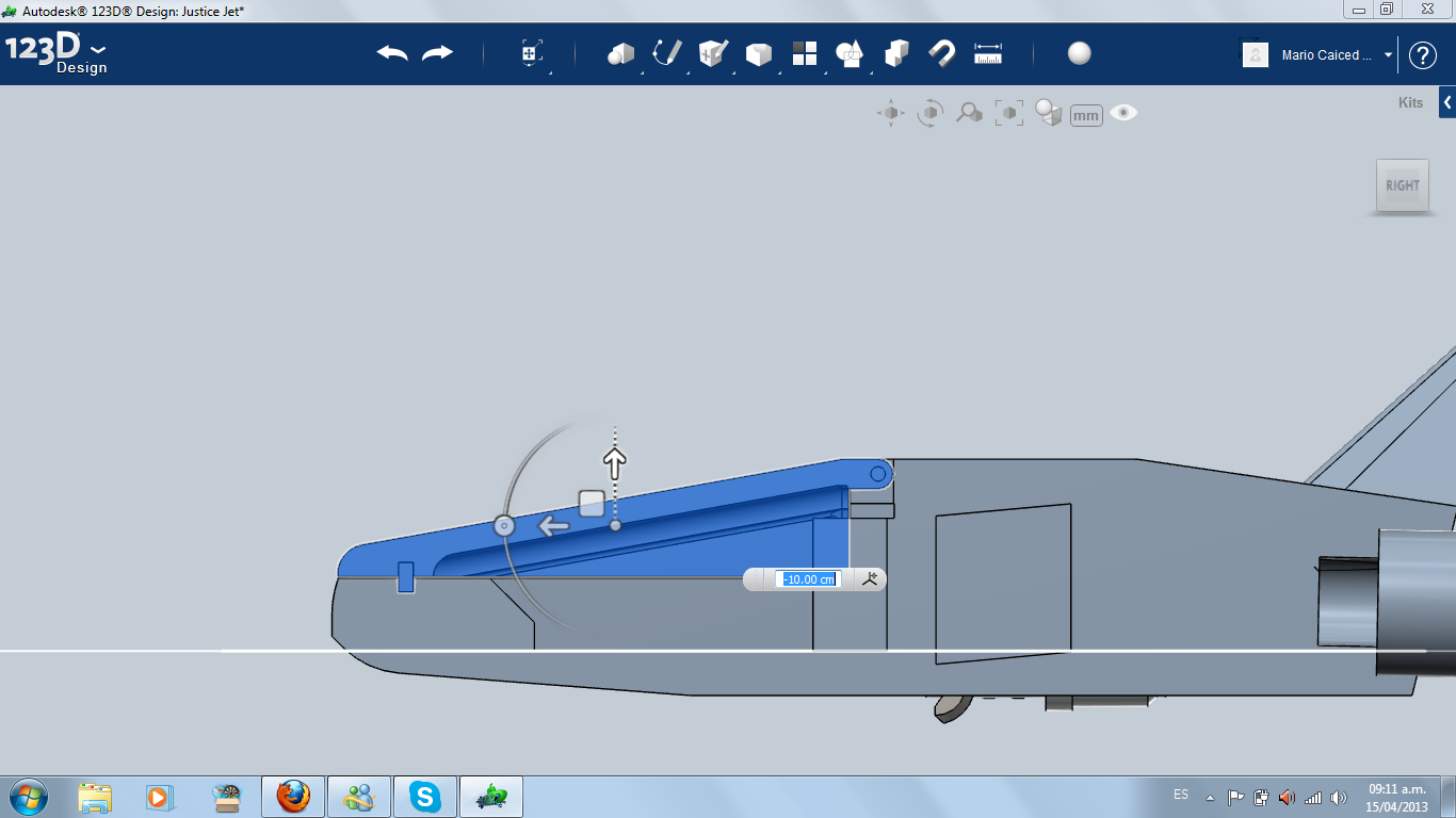
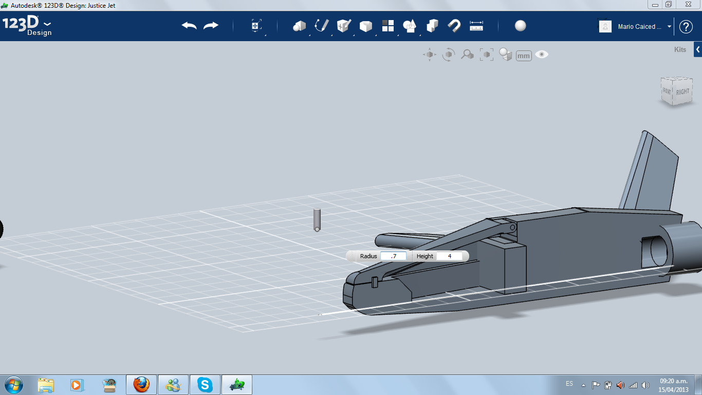
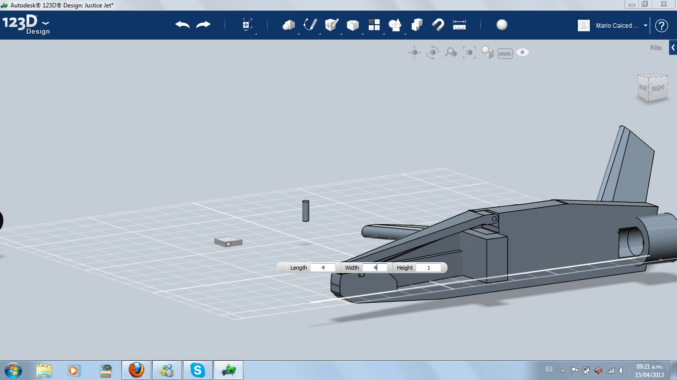
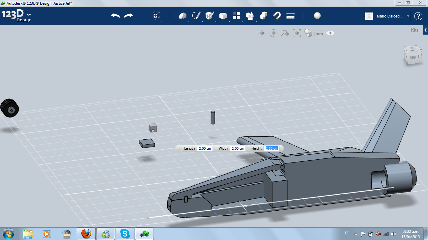
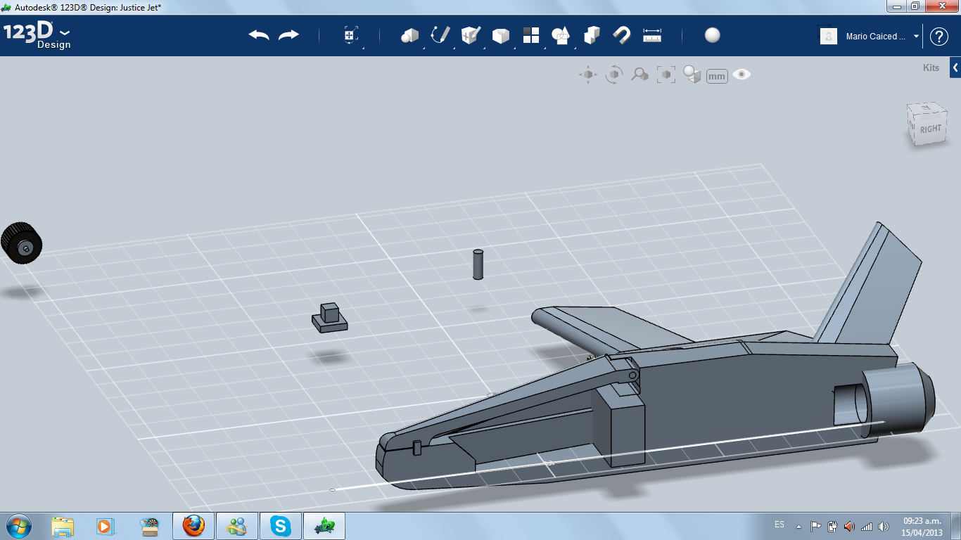
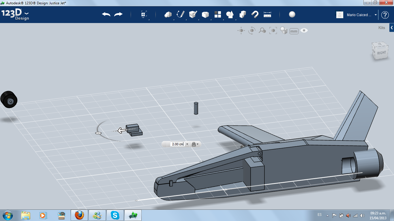
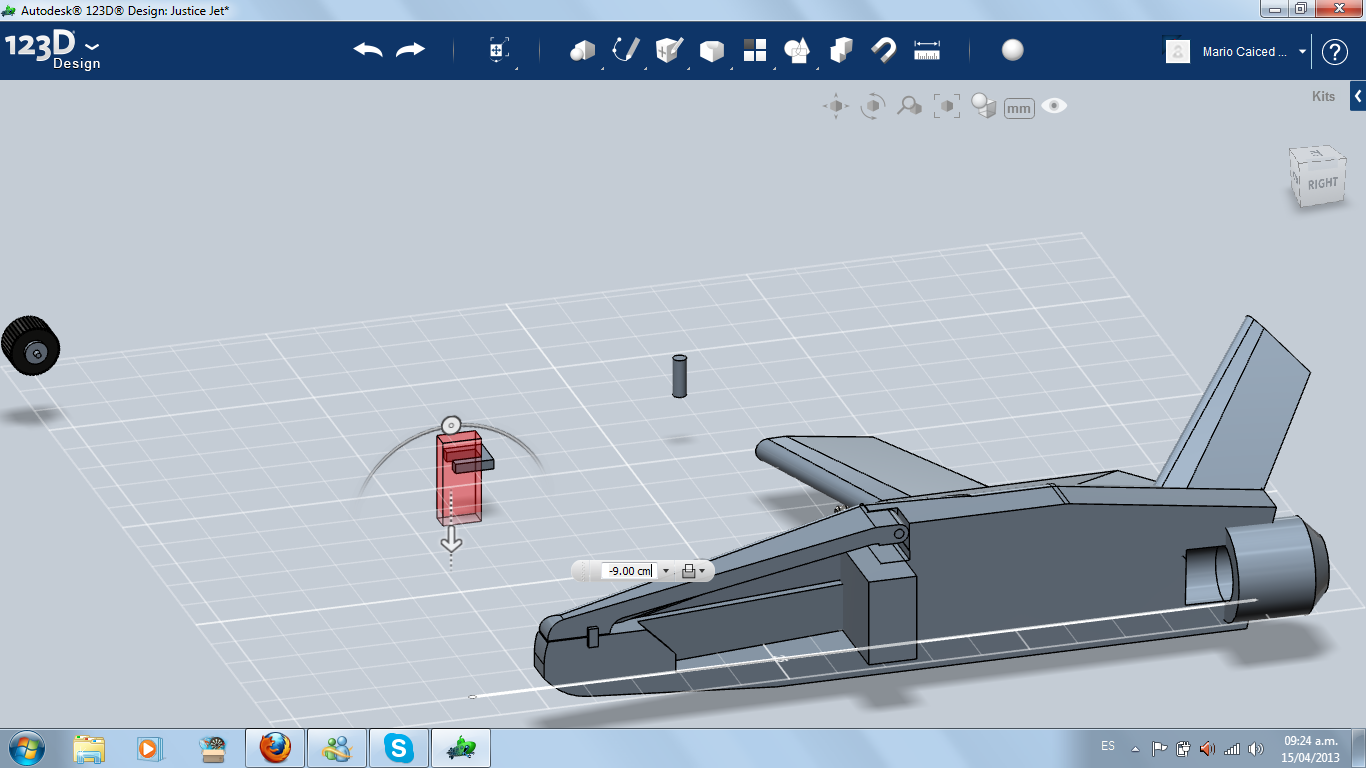
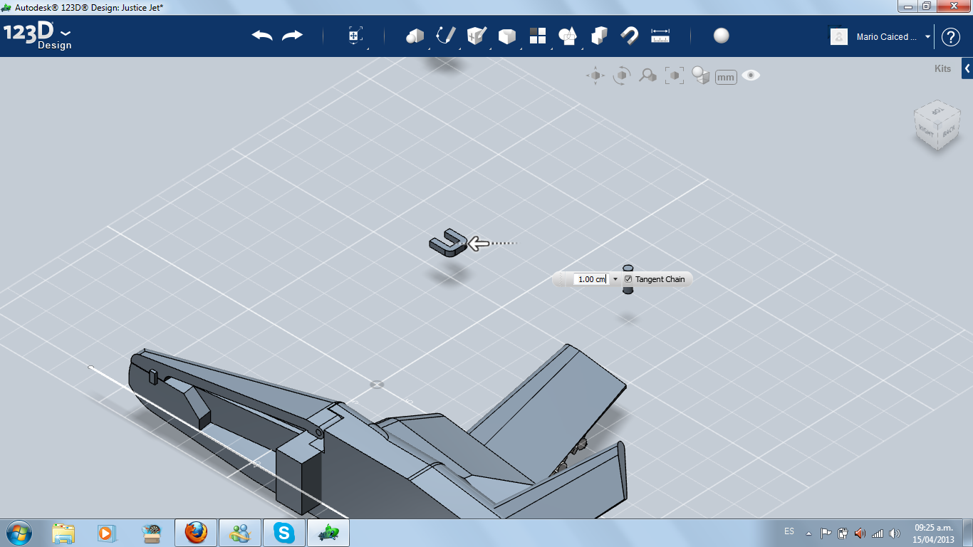
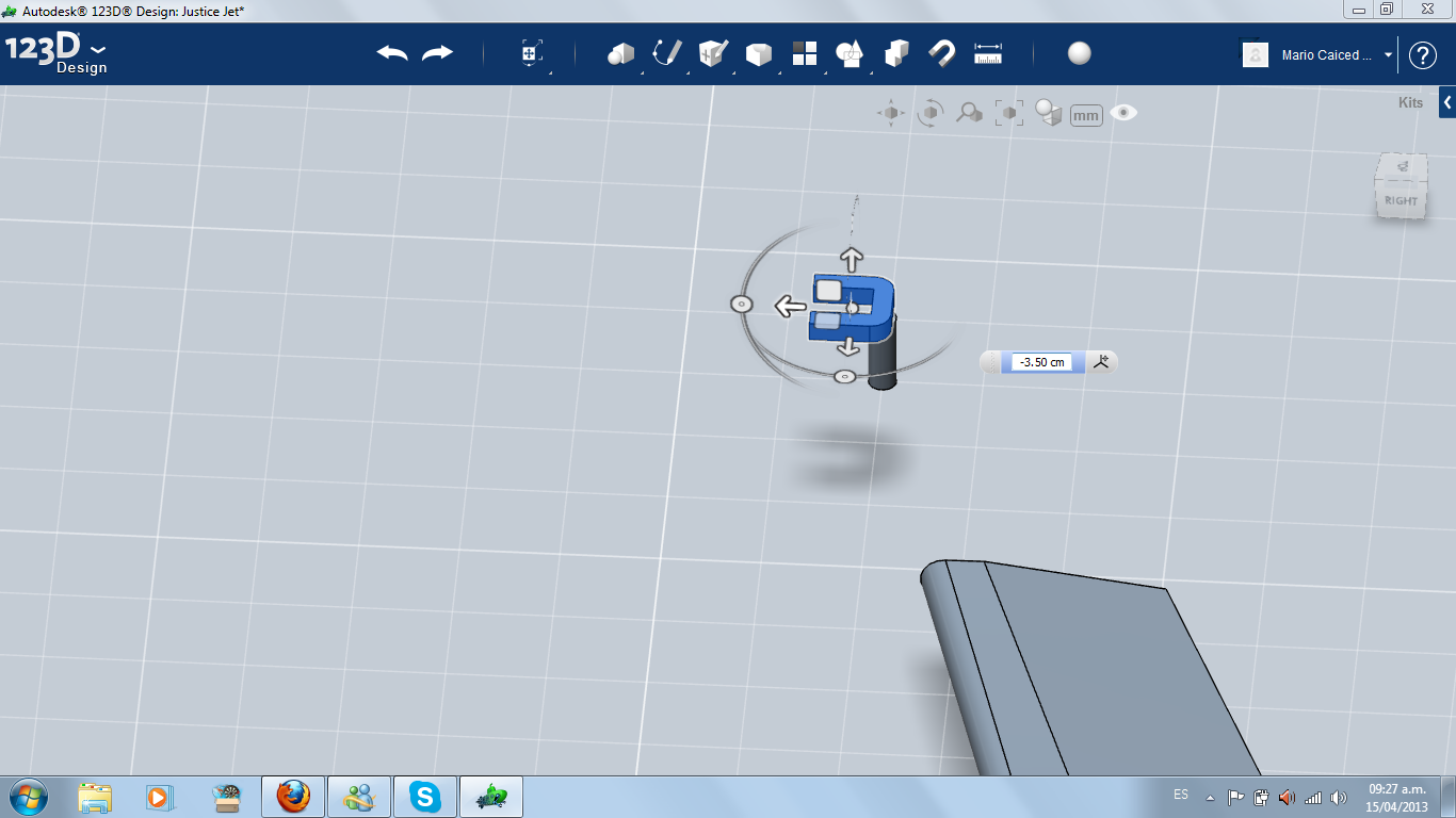
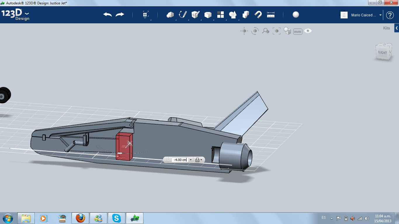
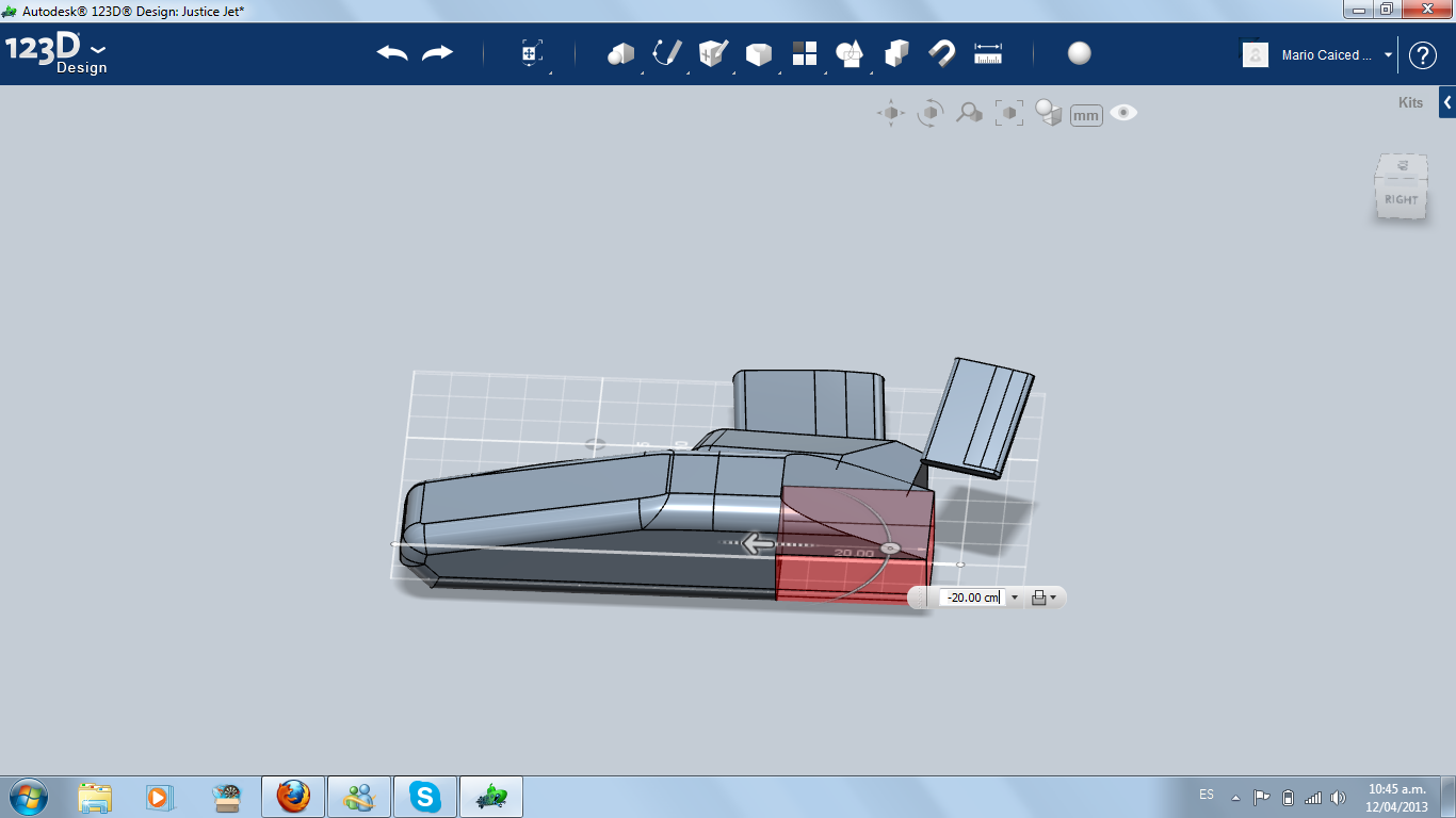
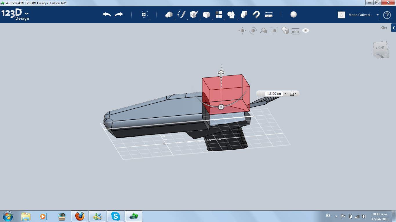
For the cockpit, I cut the higher part of the jet front. Then I transformed it into a shell. I took a part of the fuselage near the cockpit and I made a hinge, using two cylinders: one smaller for the axle and one bigger for the hole where the axle will be inserted.
Later, I opened a space for the pilot seat and I made the driving wheel using cylinders and boxes.
Later, I opened a space for the pilot seat and I made the driving wheel using cylinders and boxes.
Weapons System
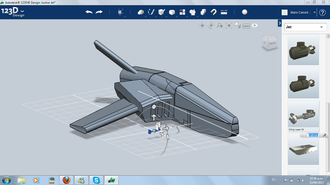
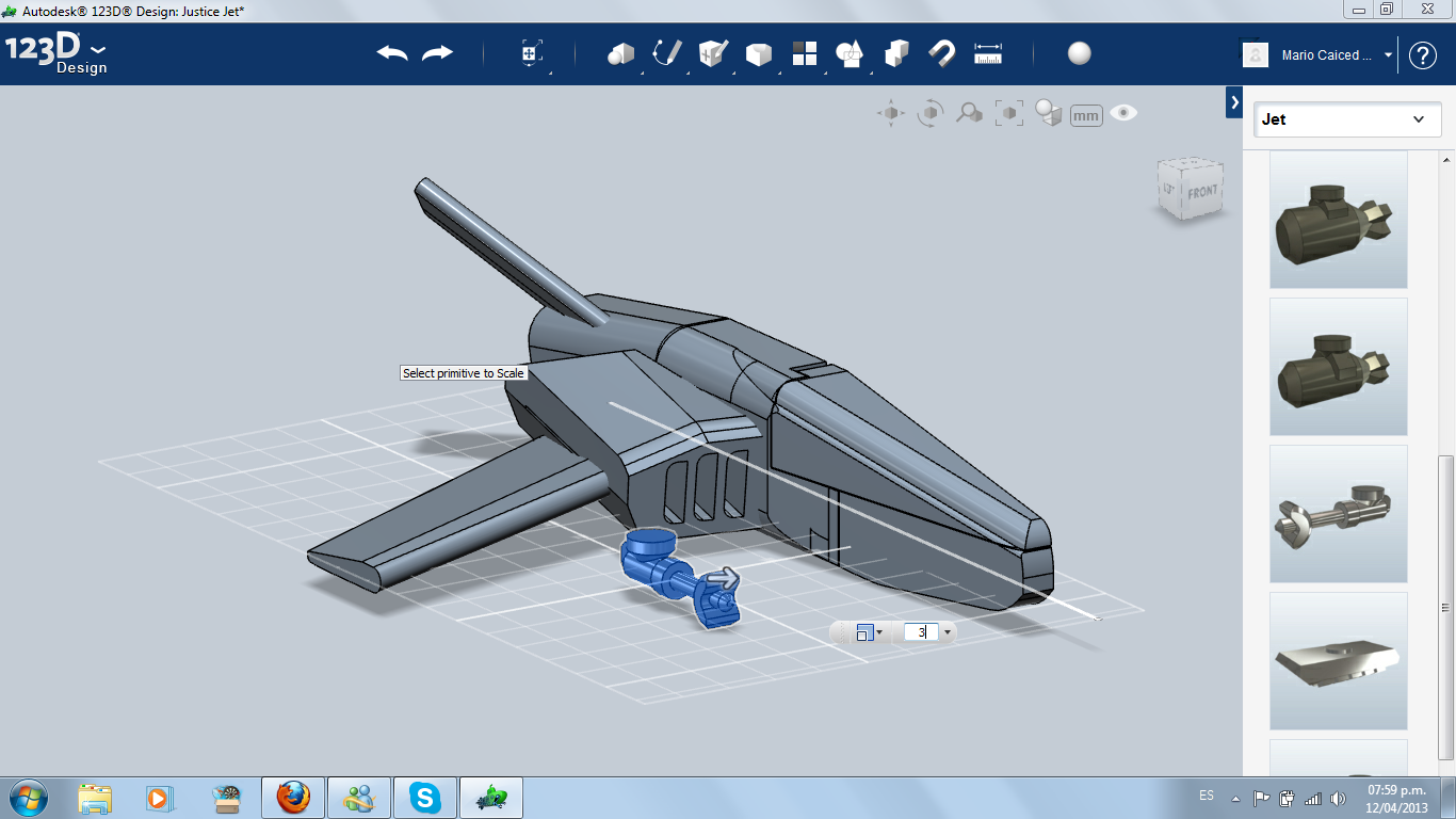
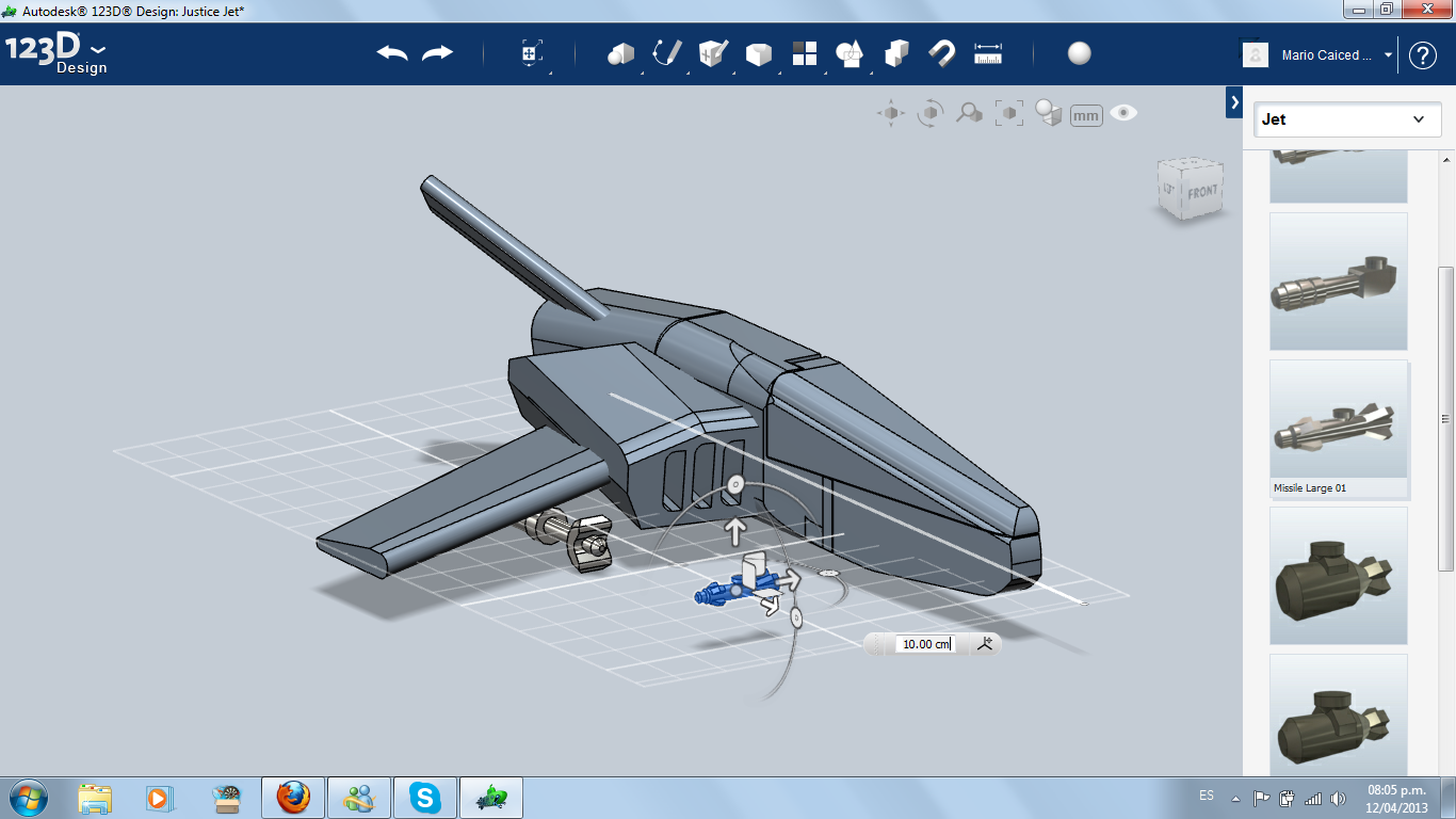
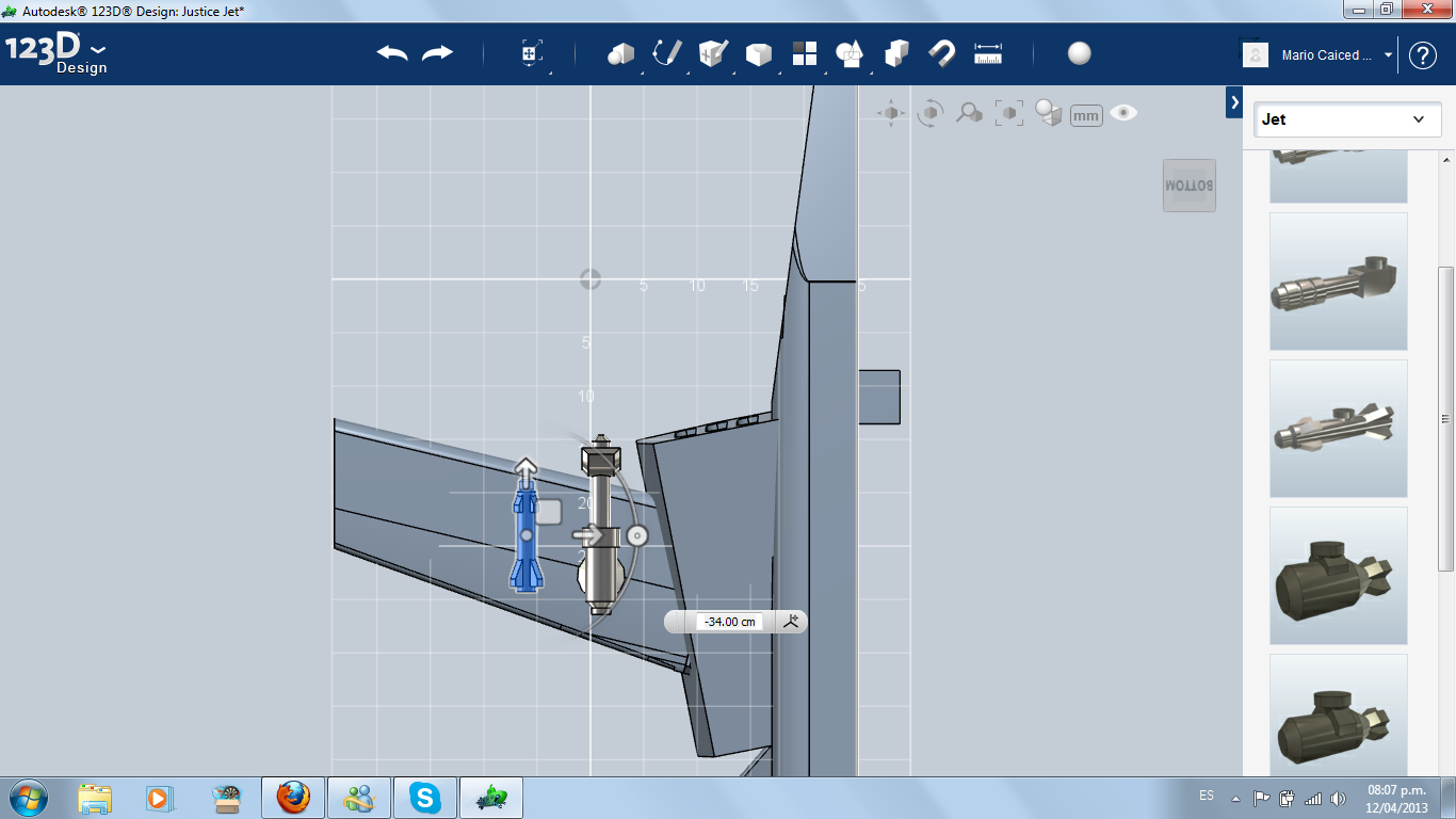
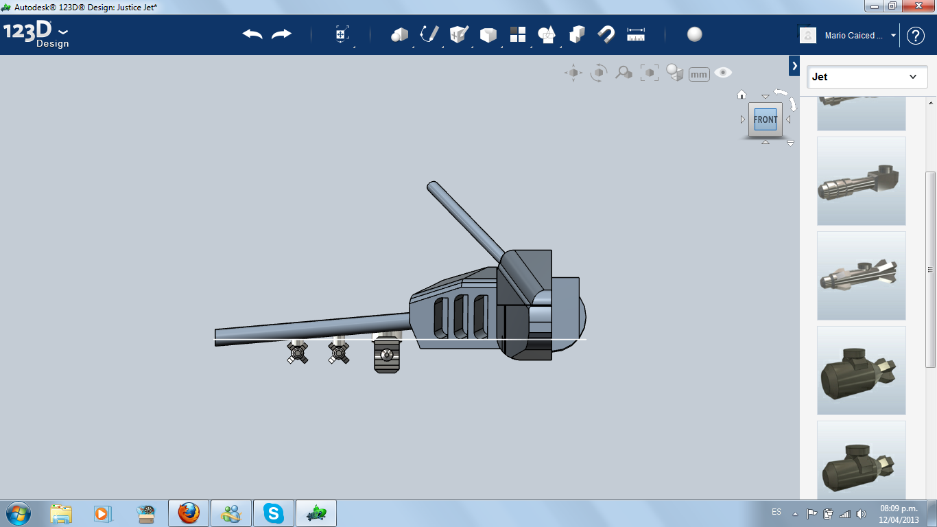
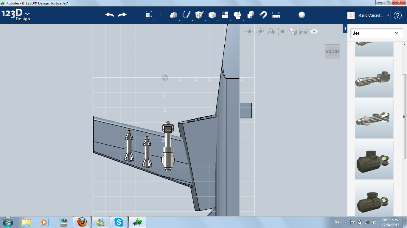
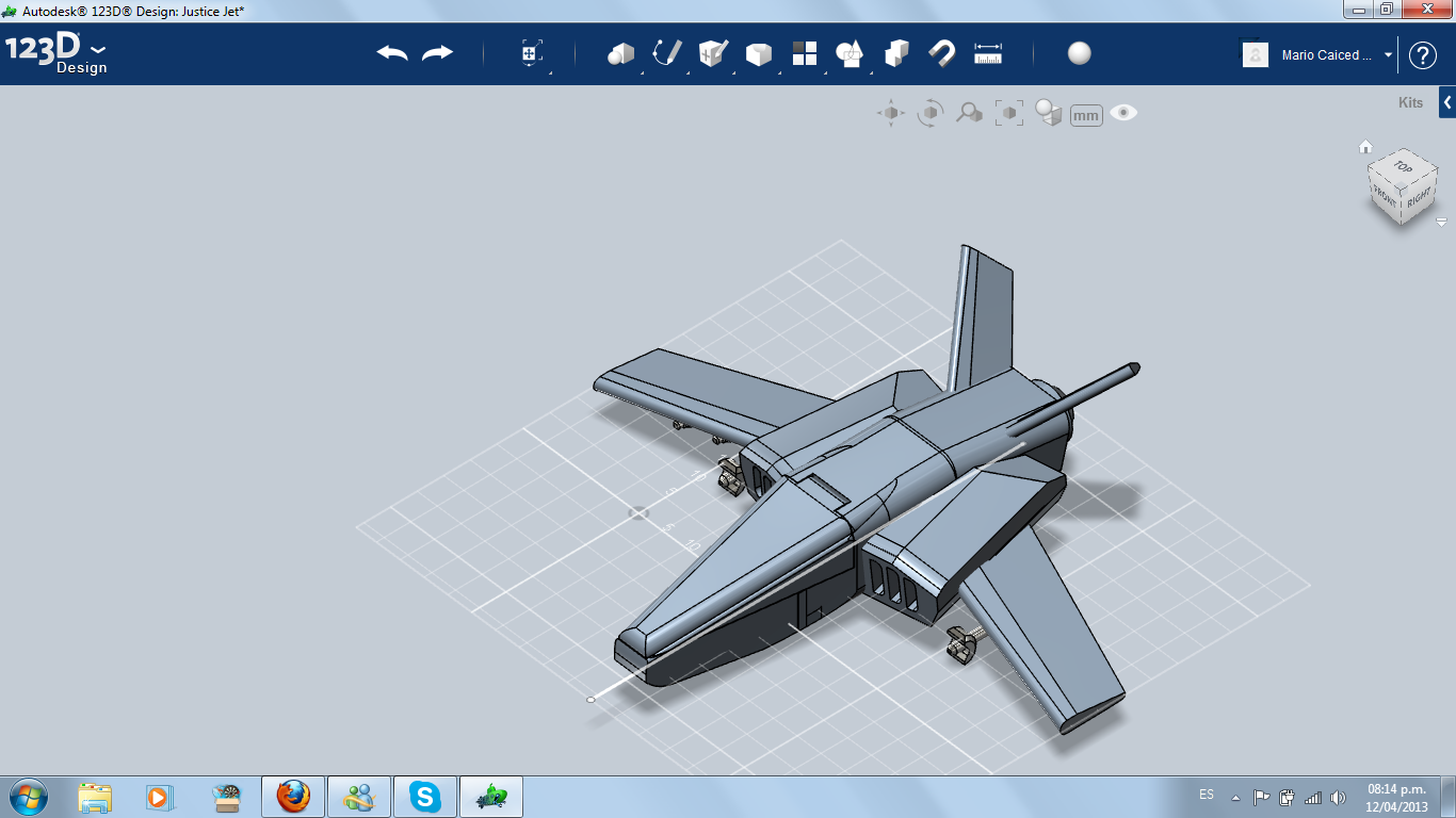
I went to the Online Kits, Jet category, Armament. I aumented the size and installed a Wing Laser and two Missile Large below the wing.
Landing Gear (front)
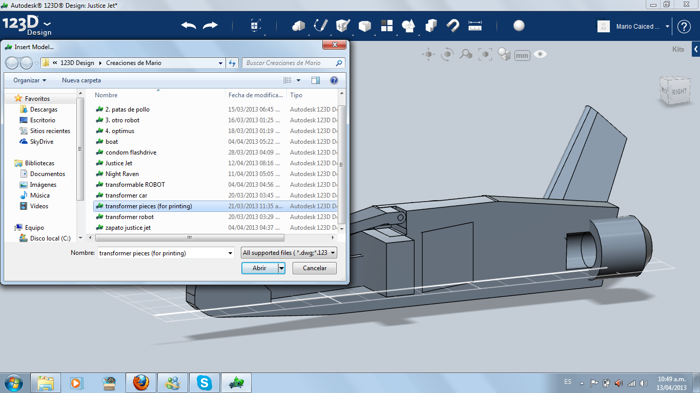
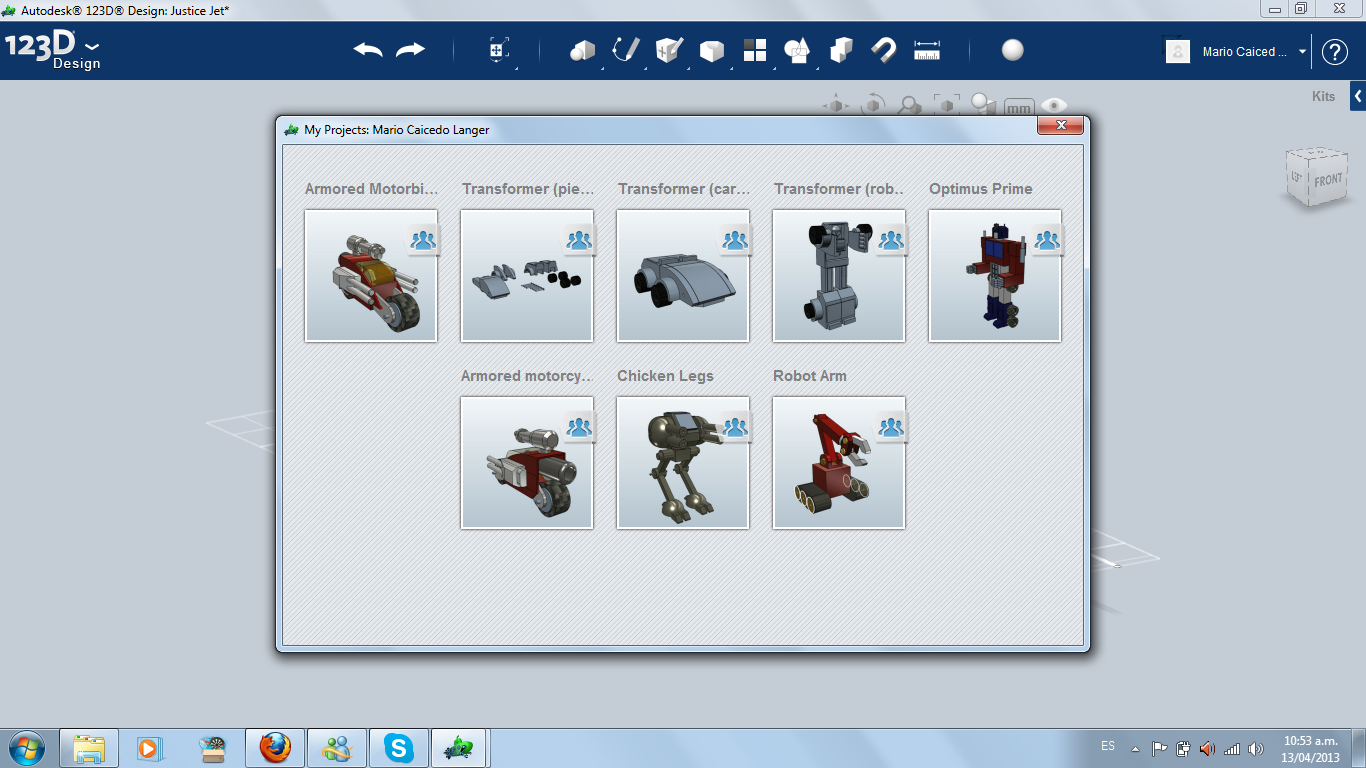
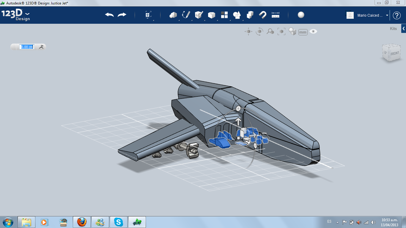
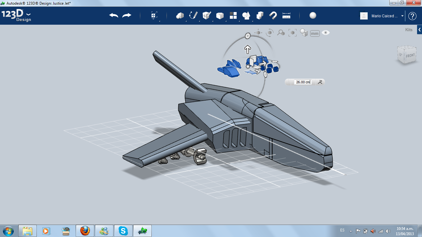
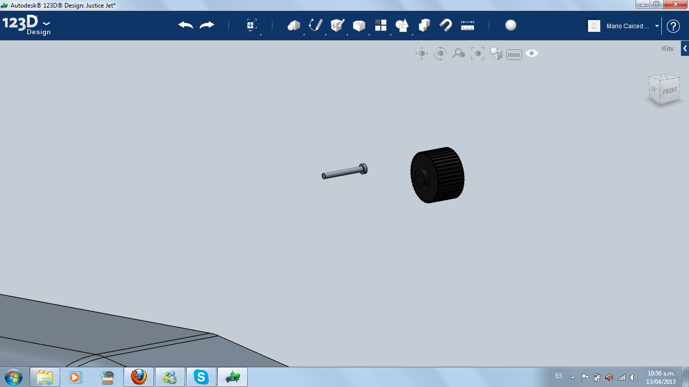
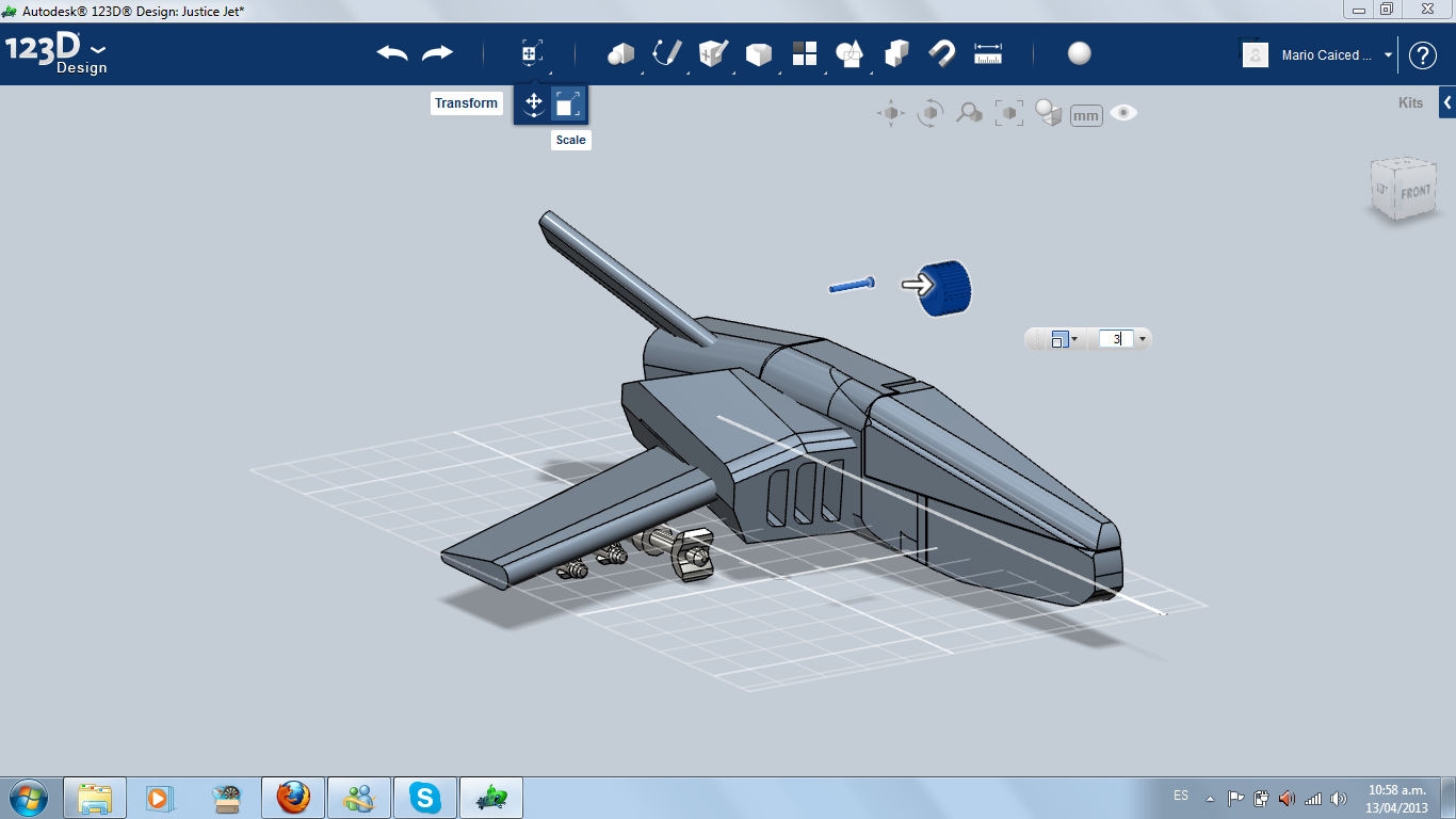
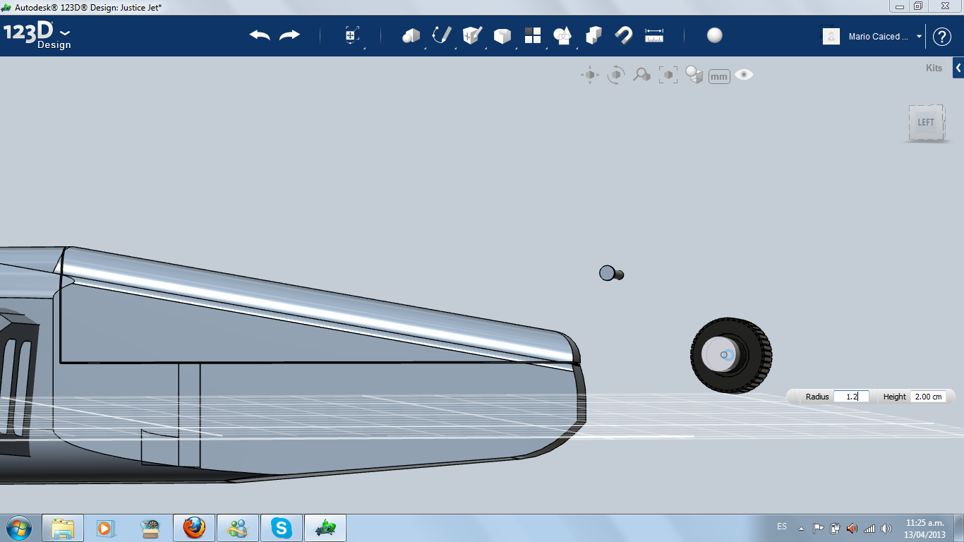
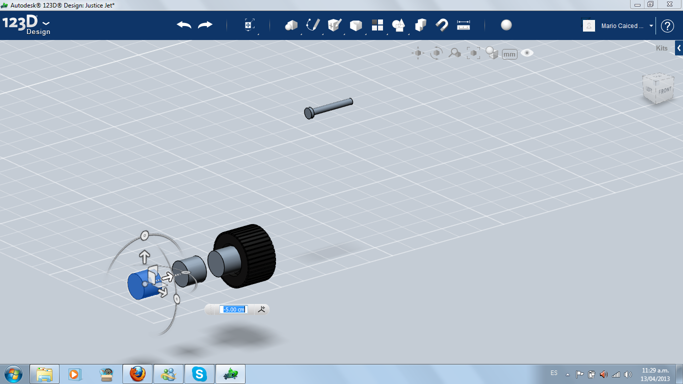
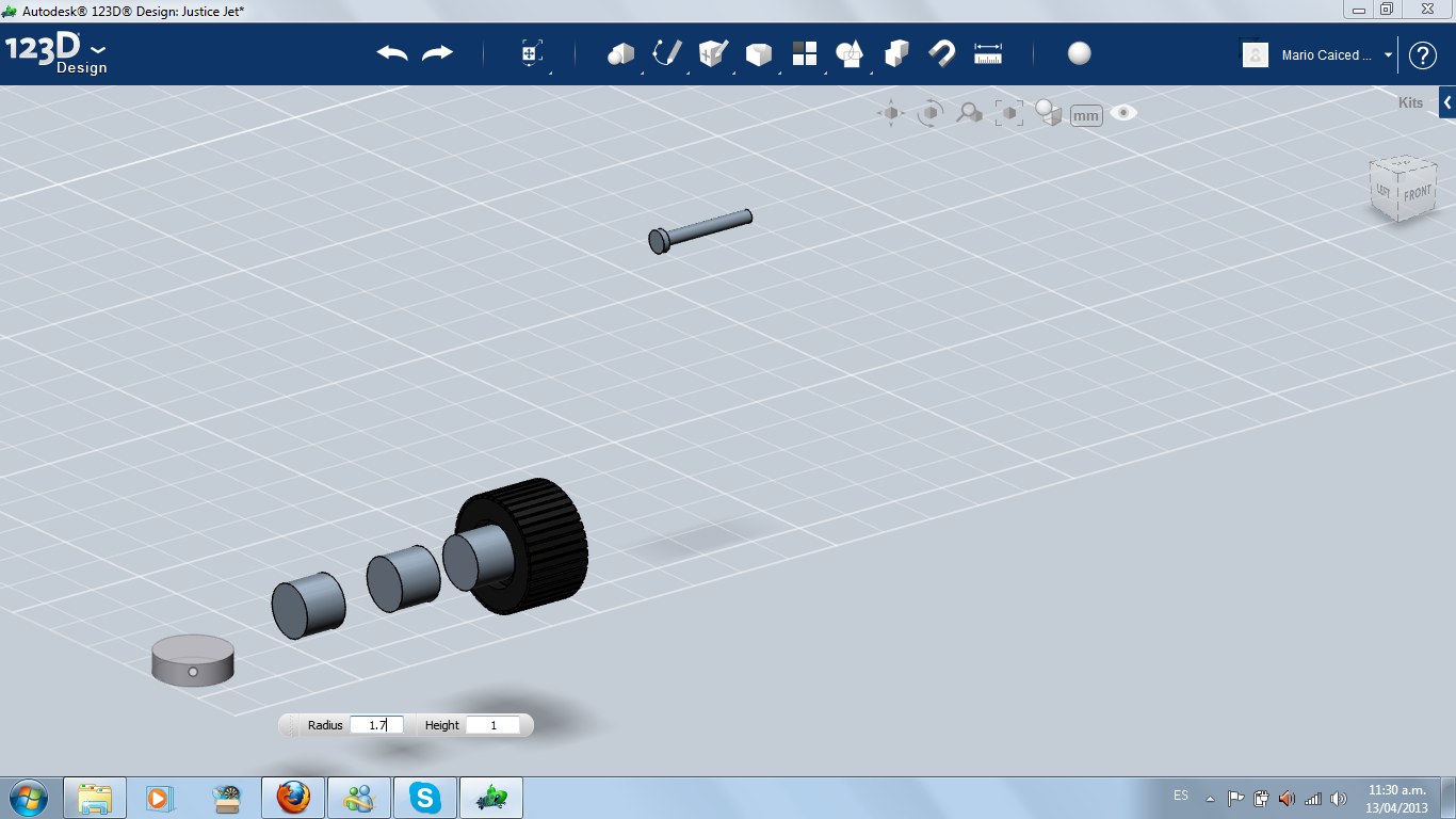
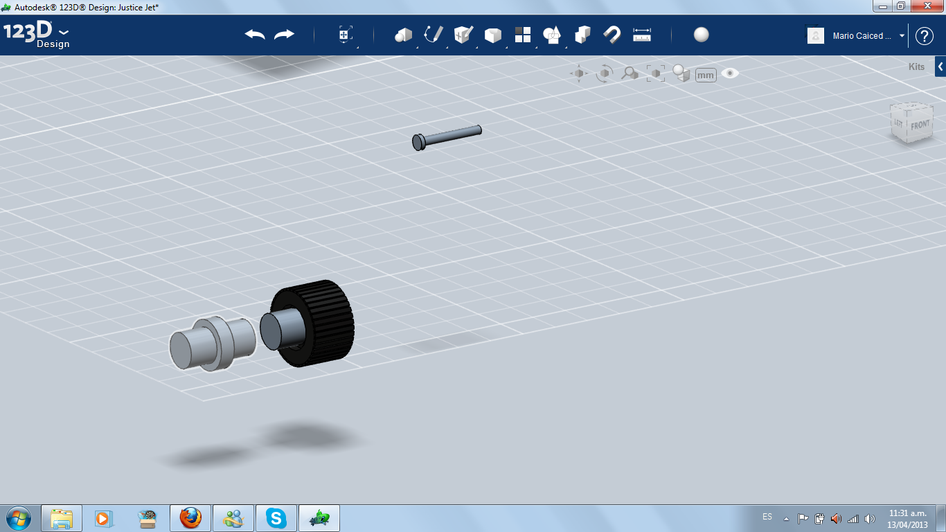
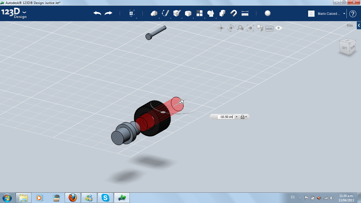
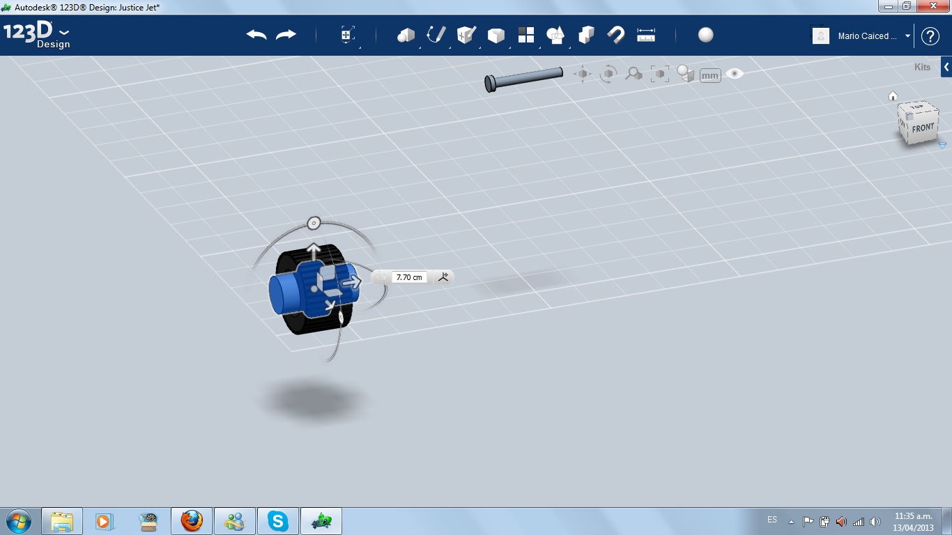
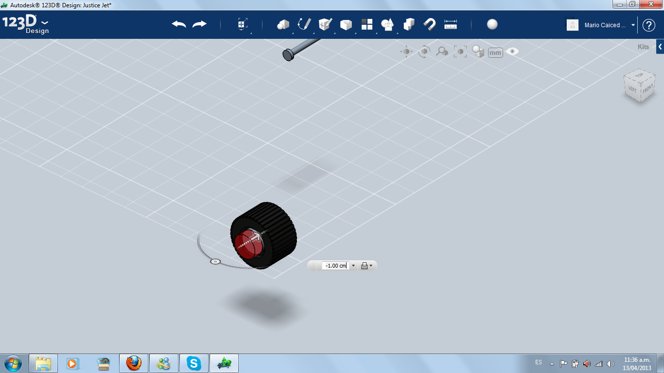
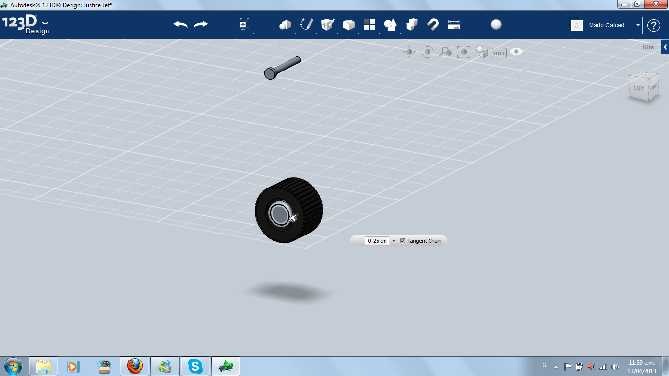
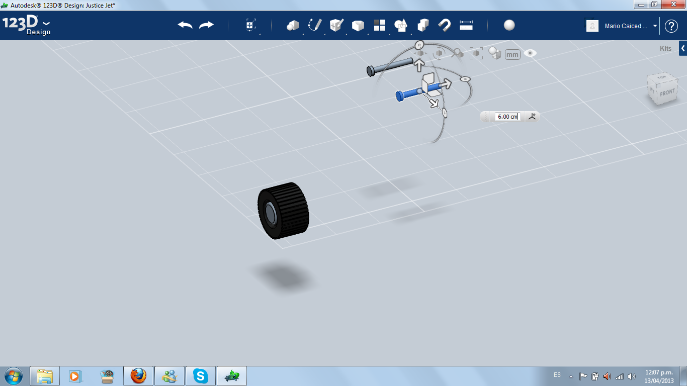
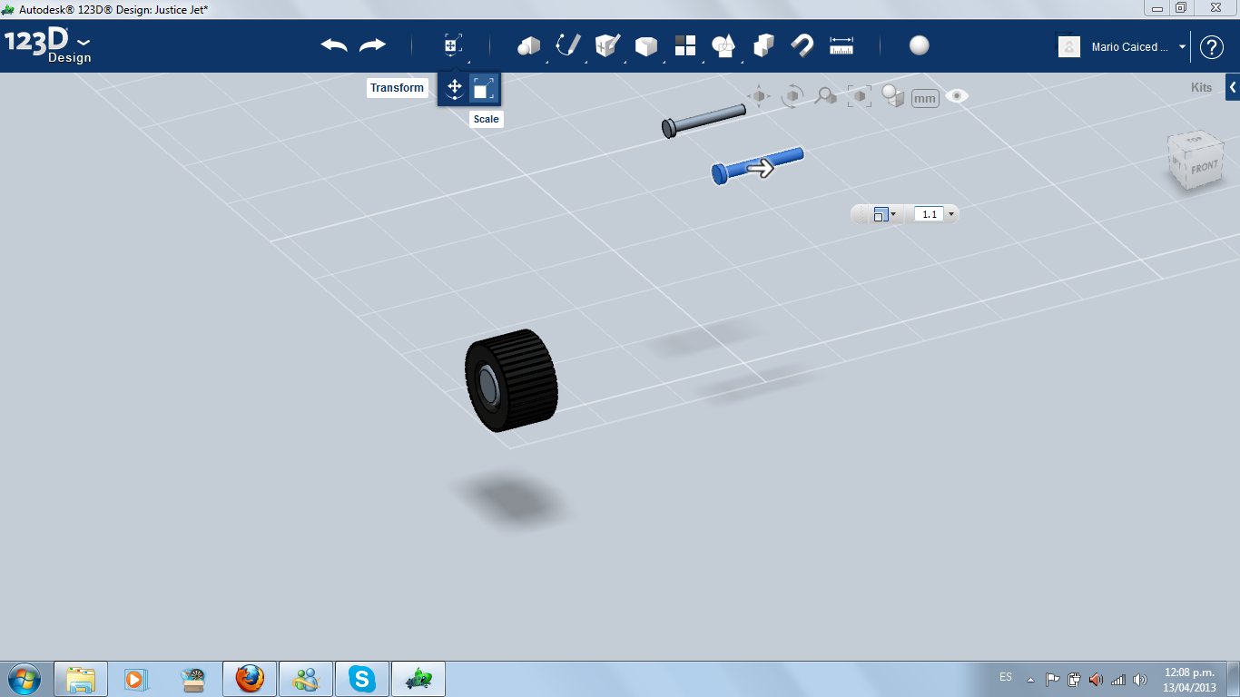
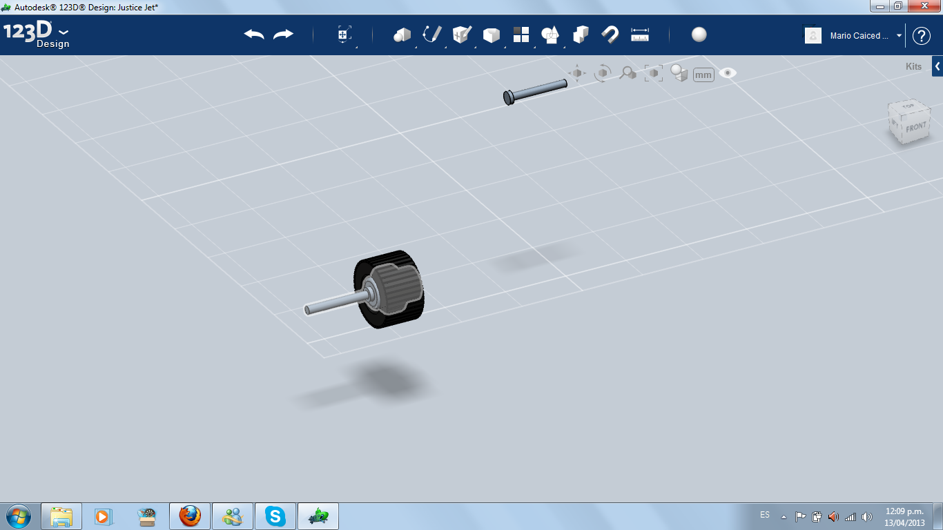
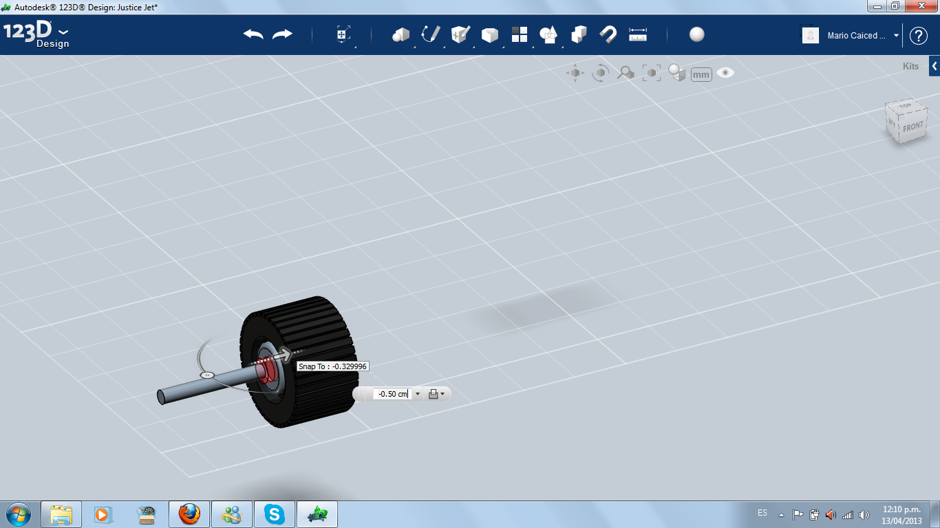
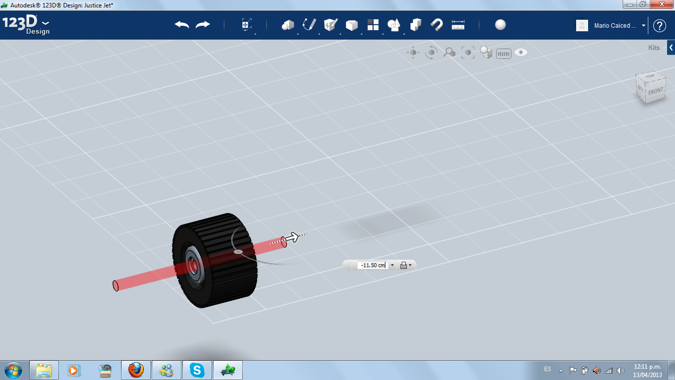
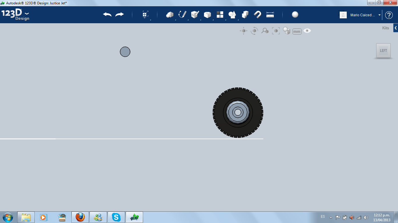
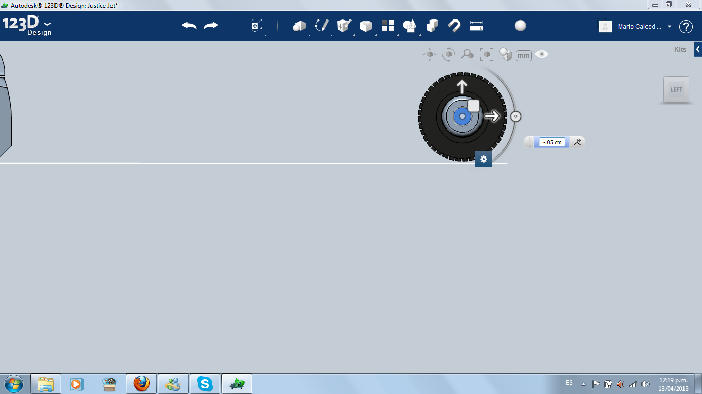
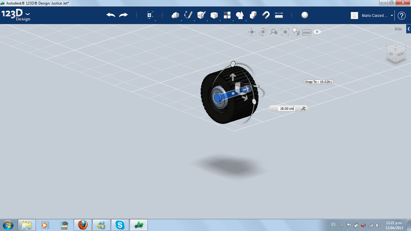
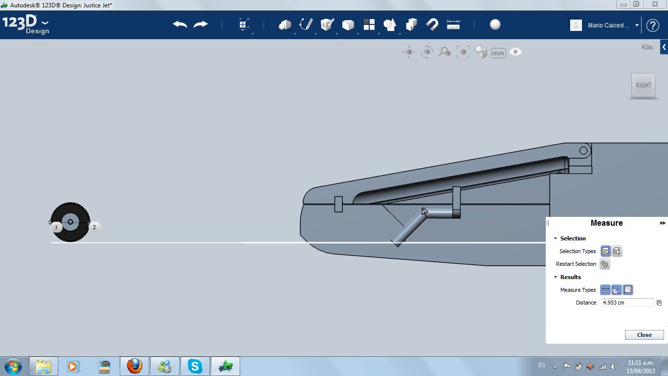
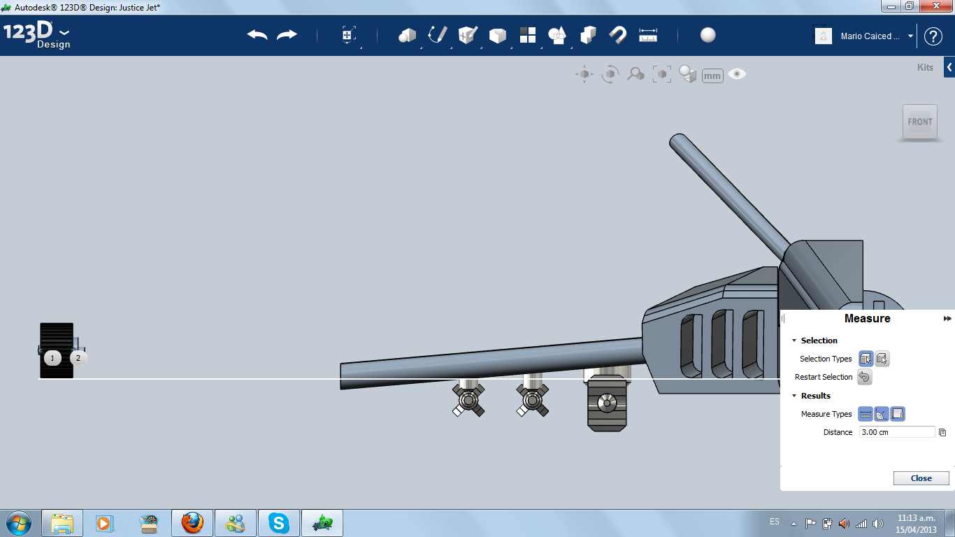
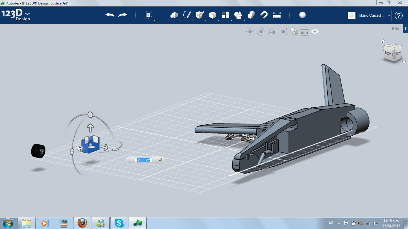
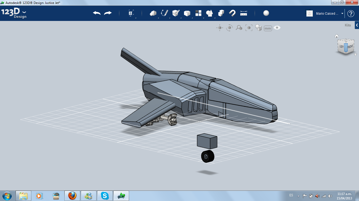
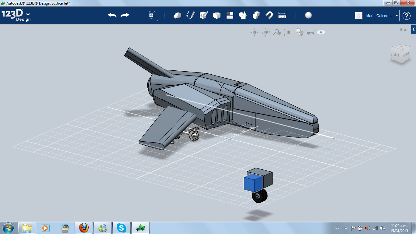
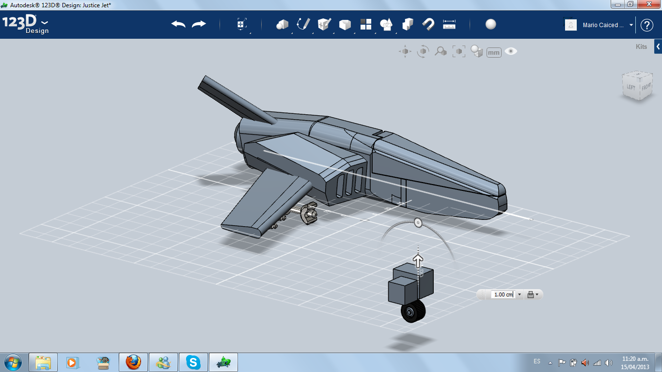
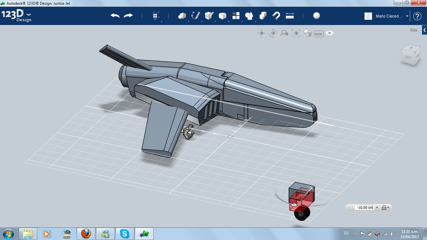
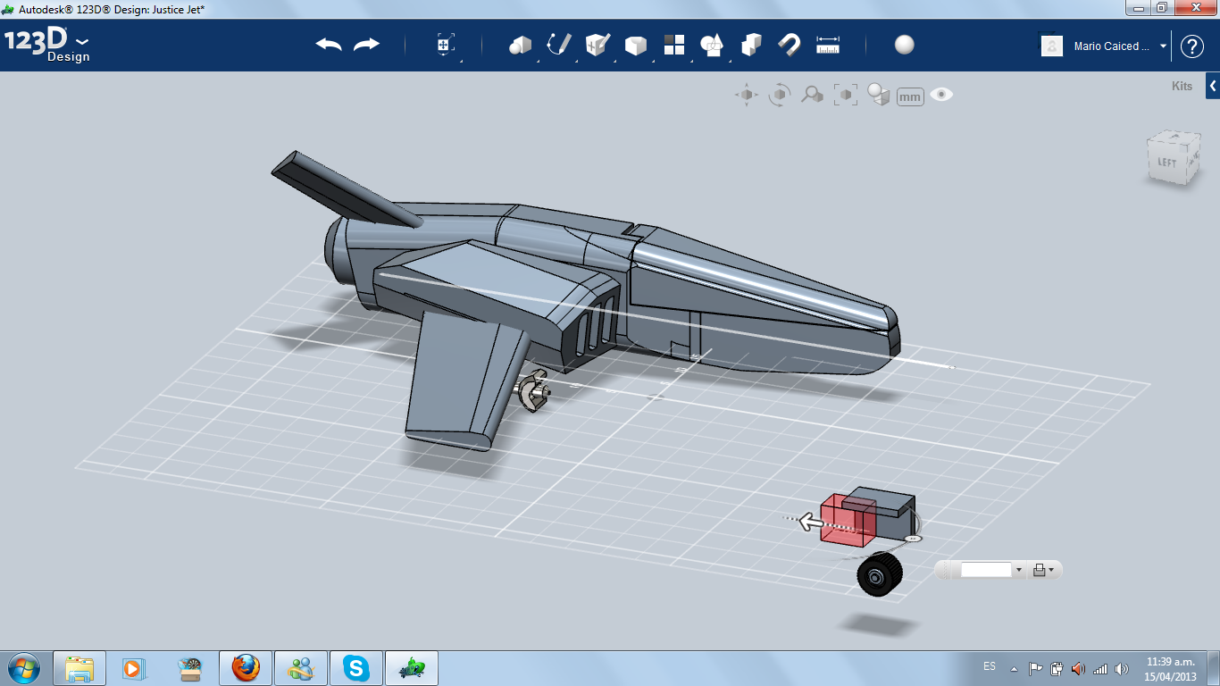
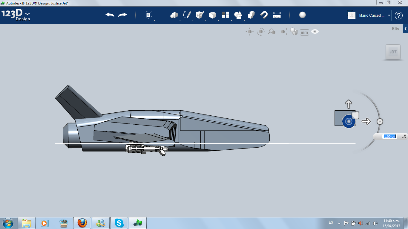
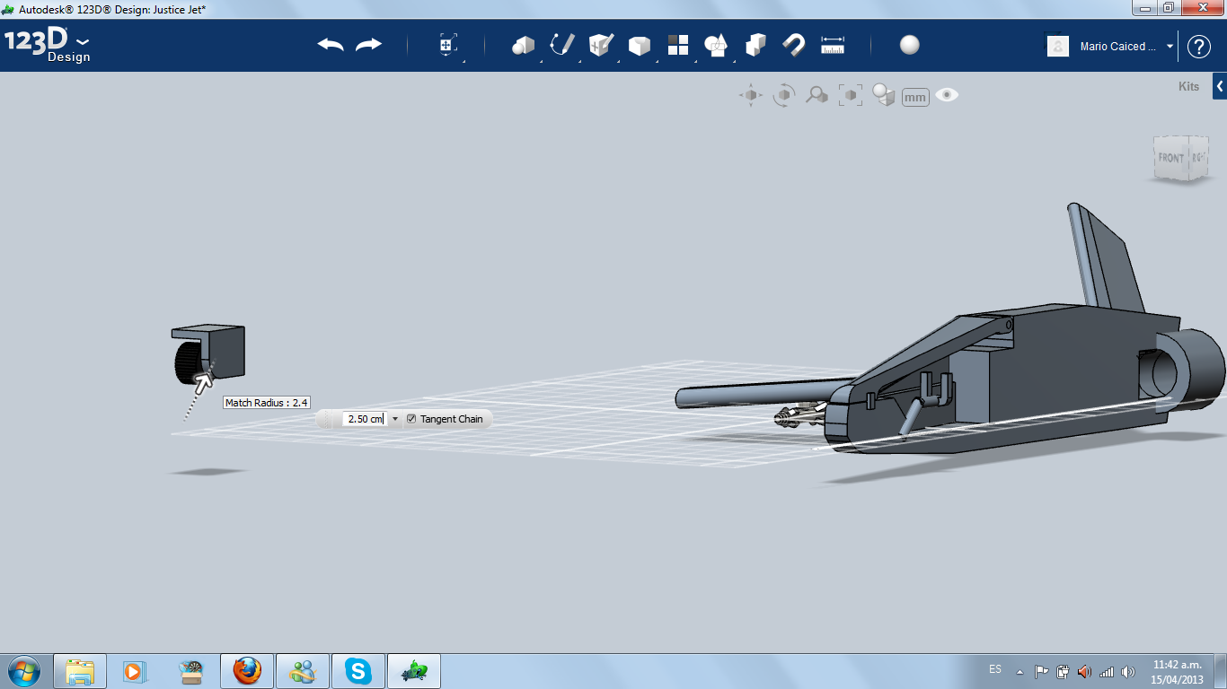
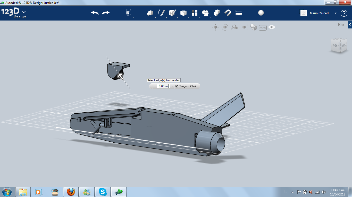
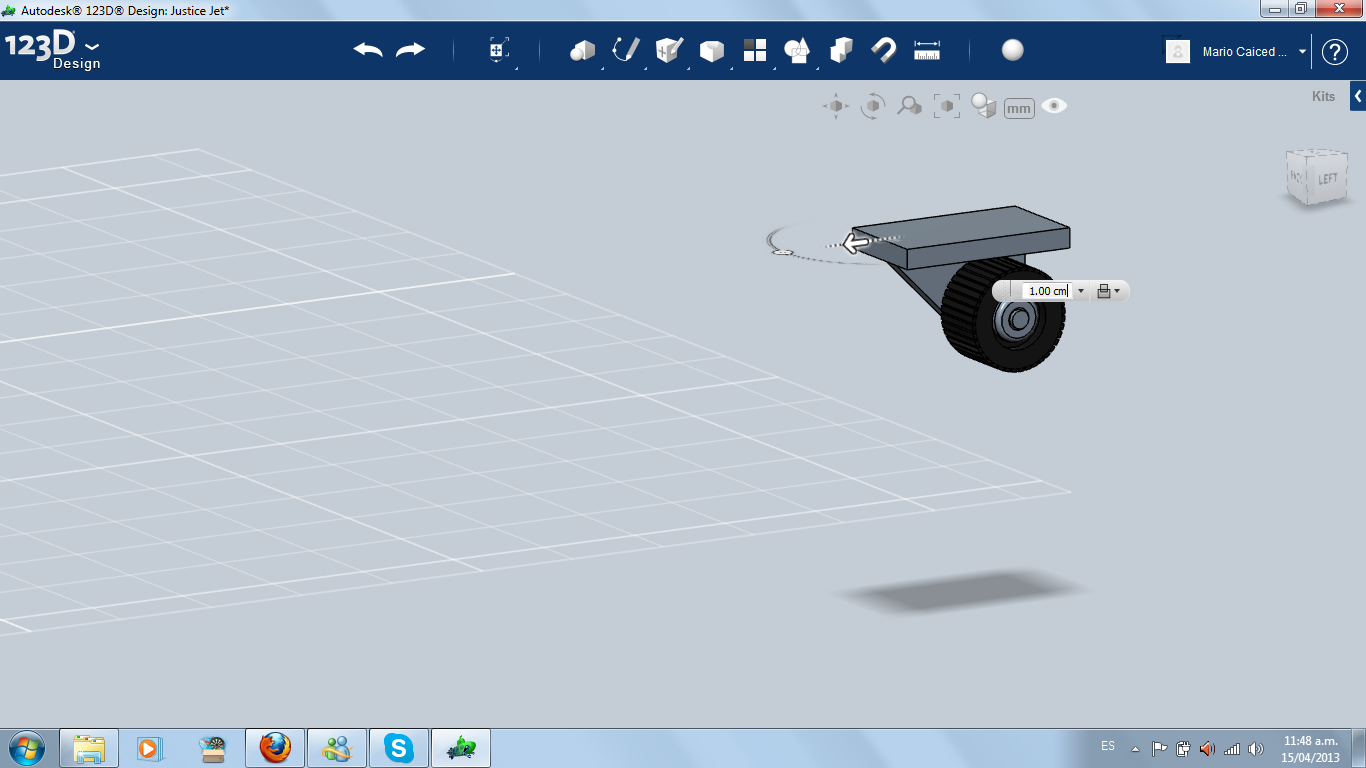
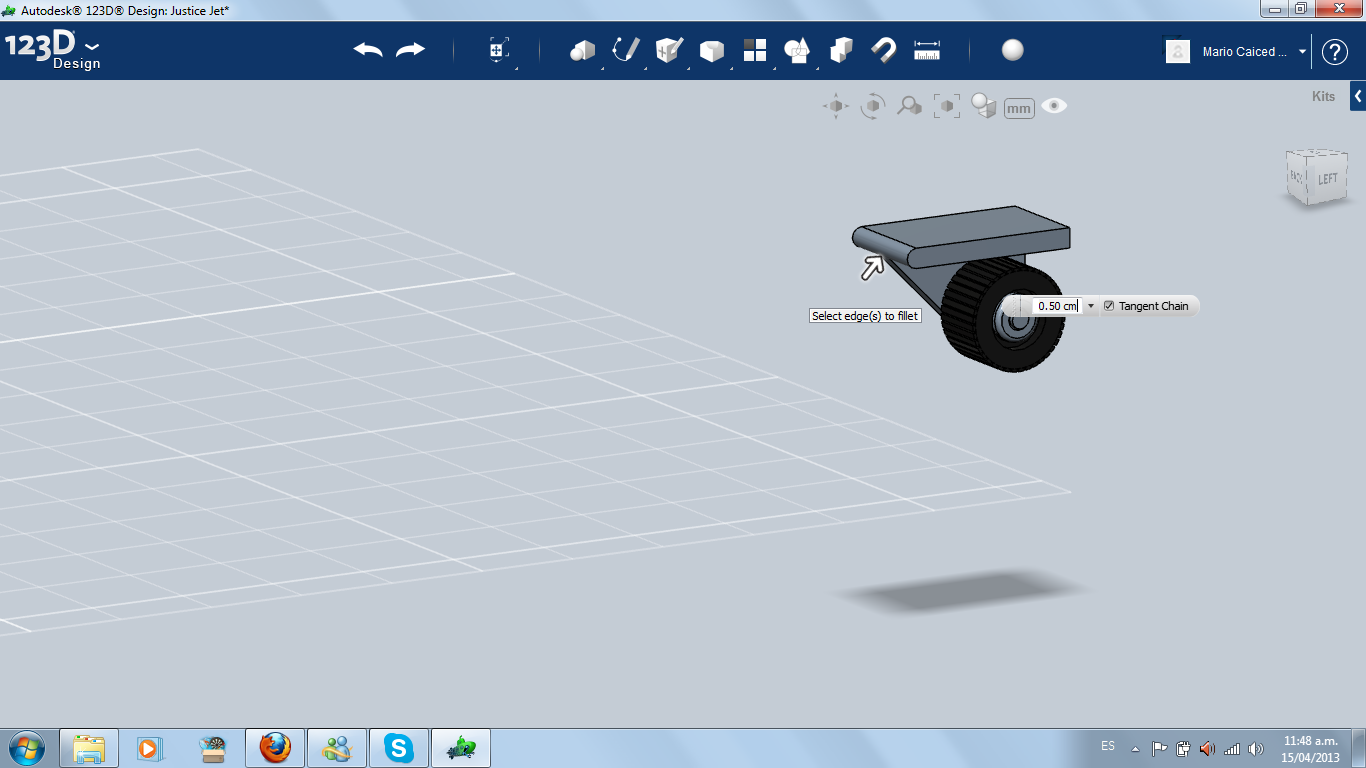
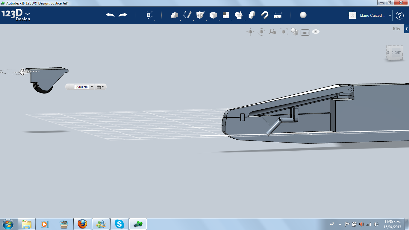
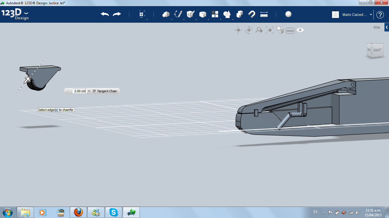
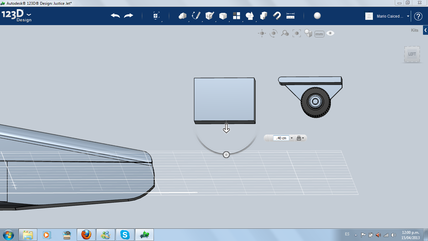
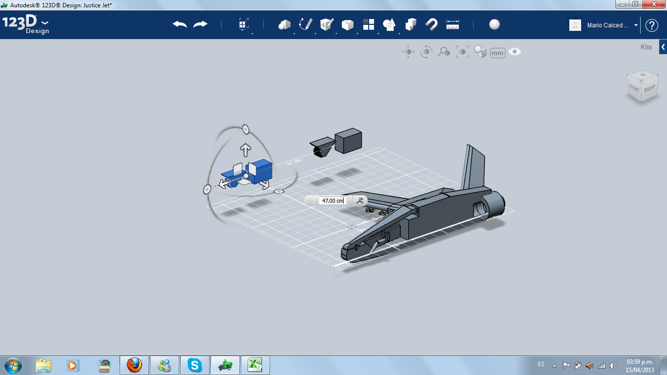
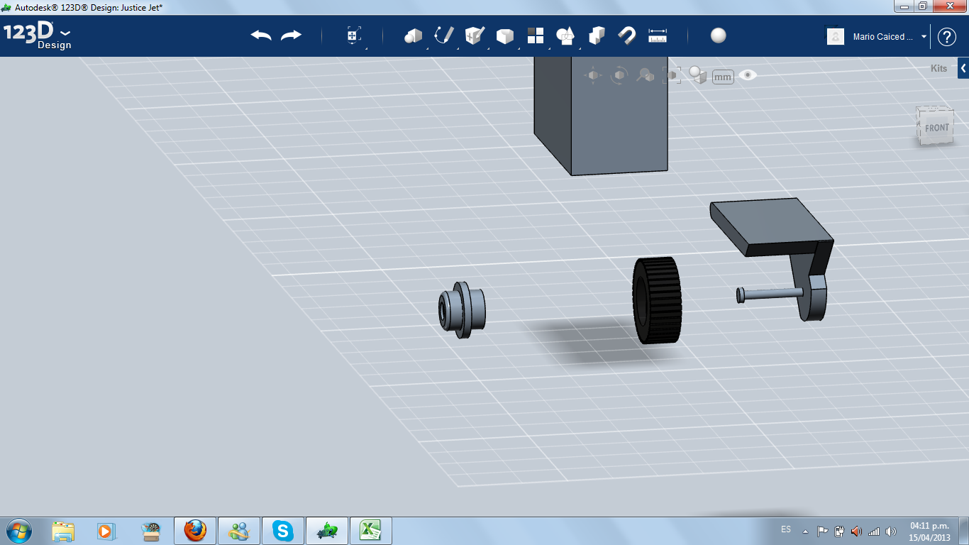
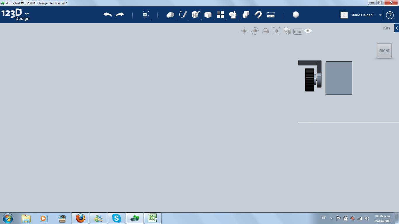
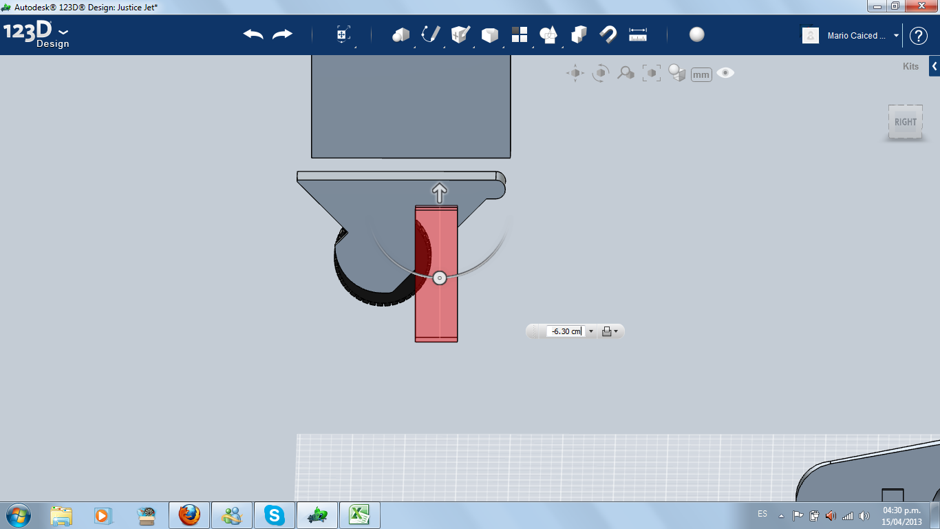
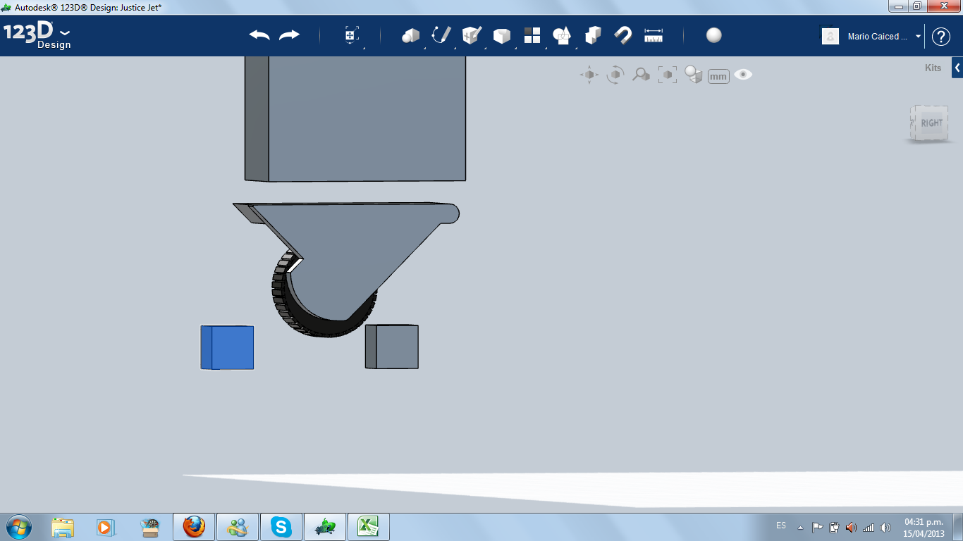
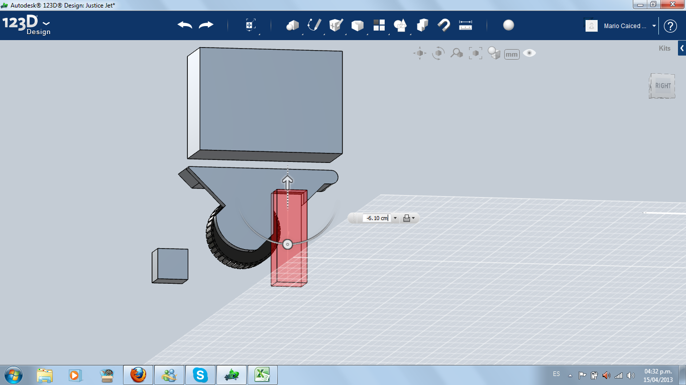
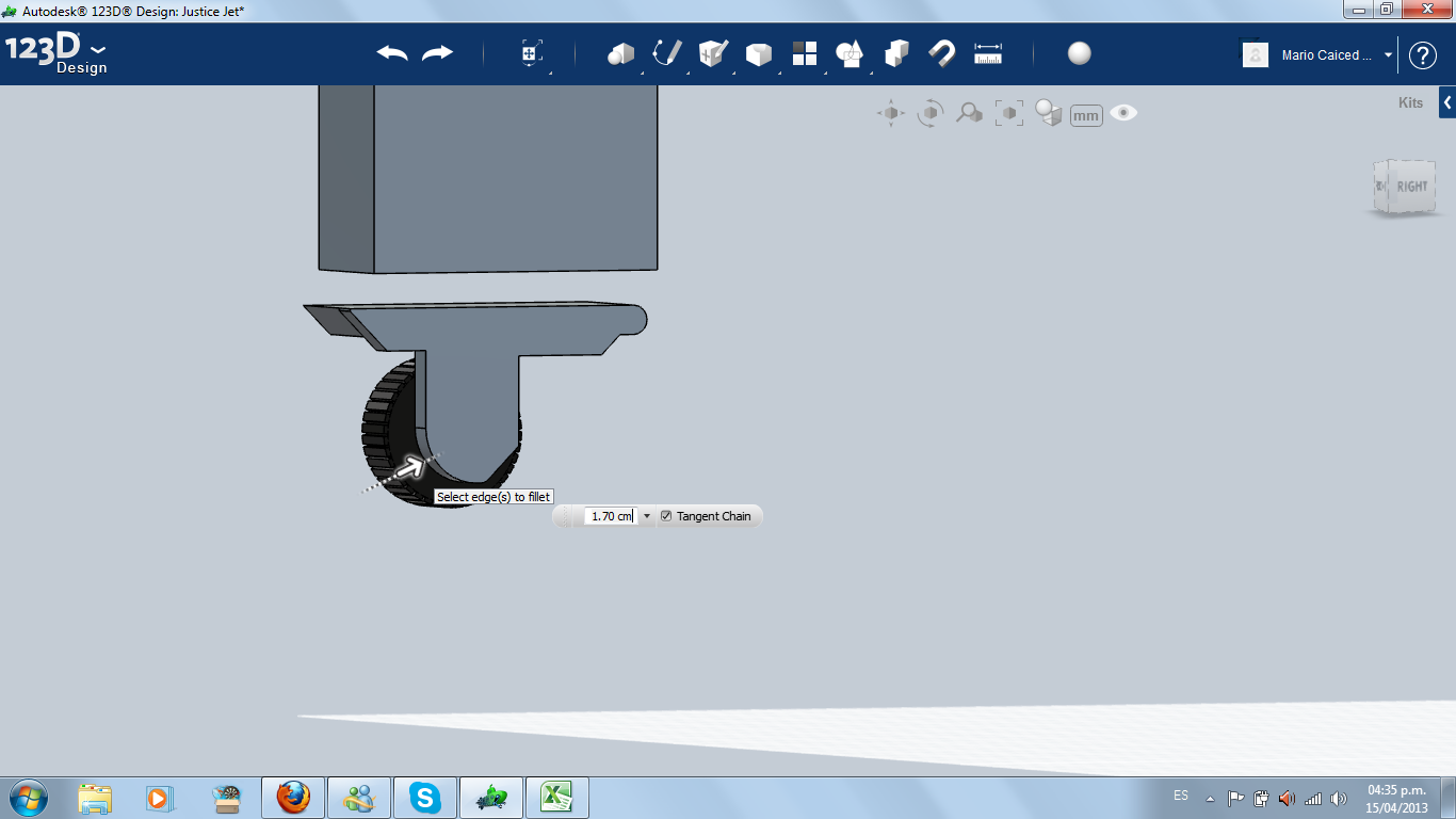
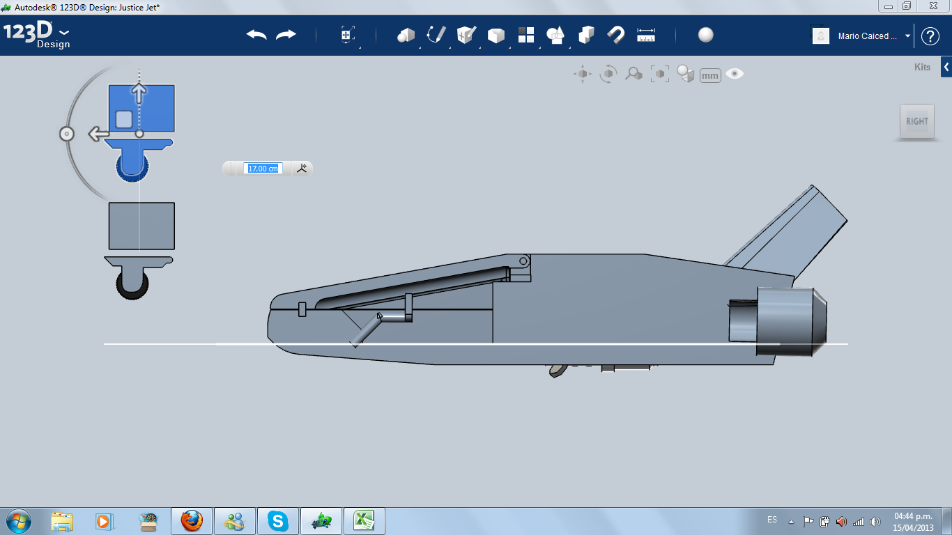
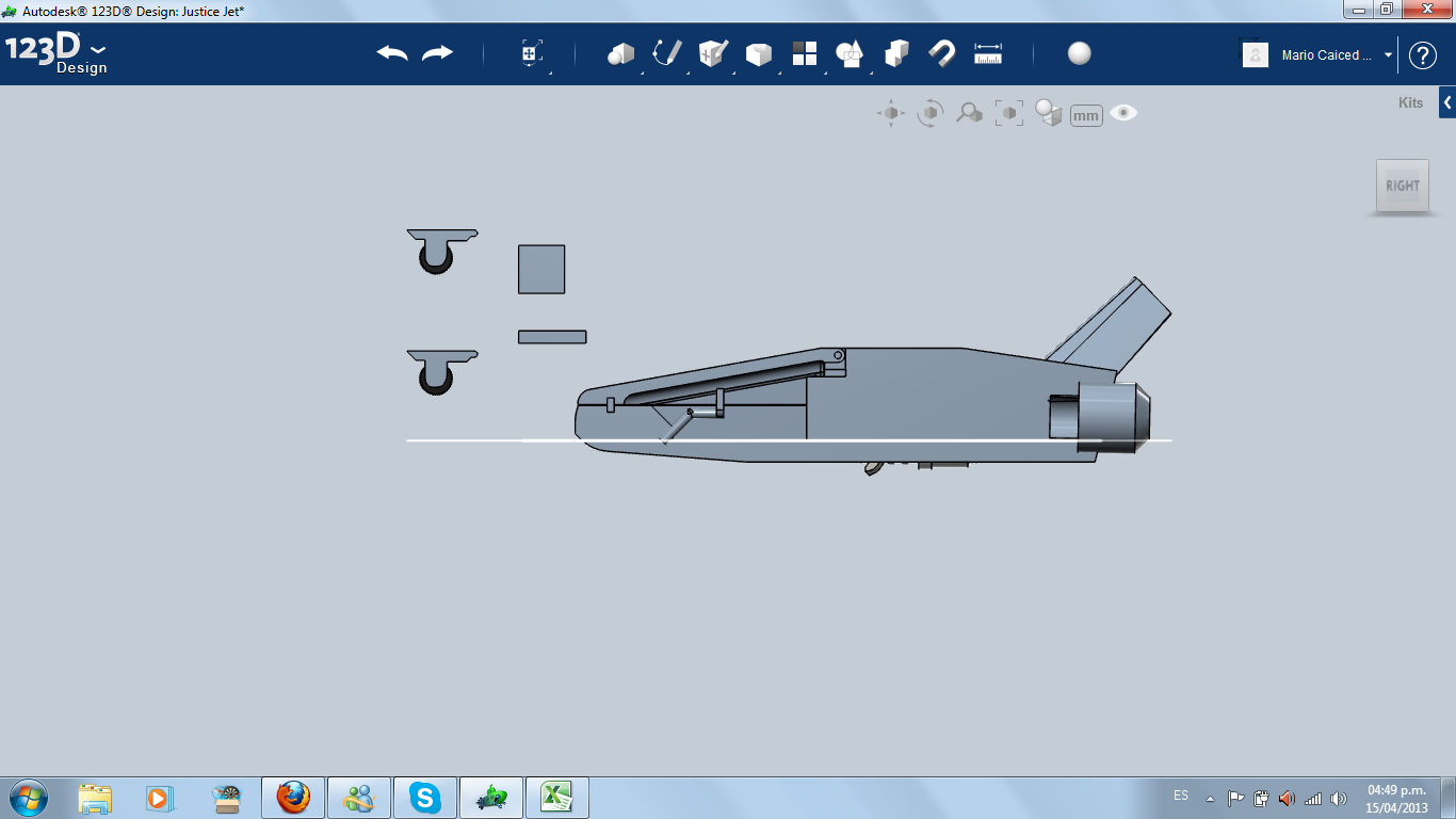
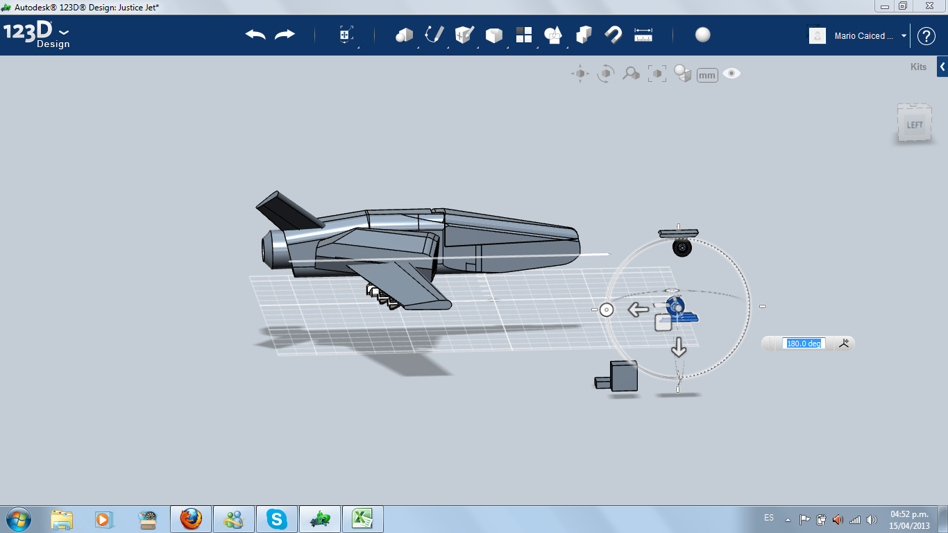
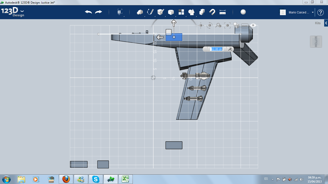
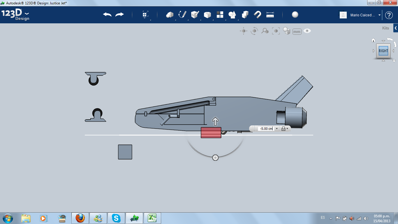
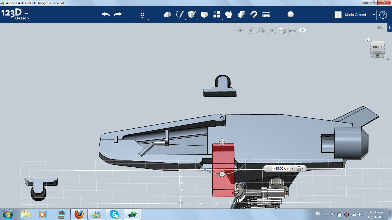
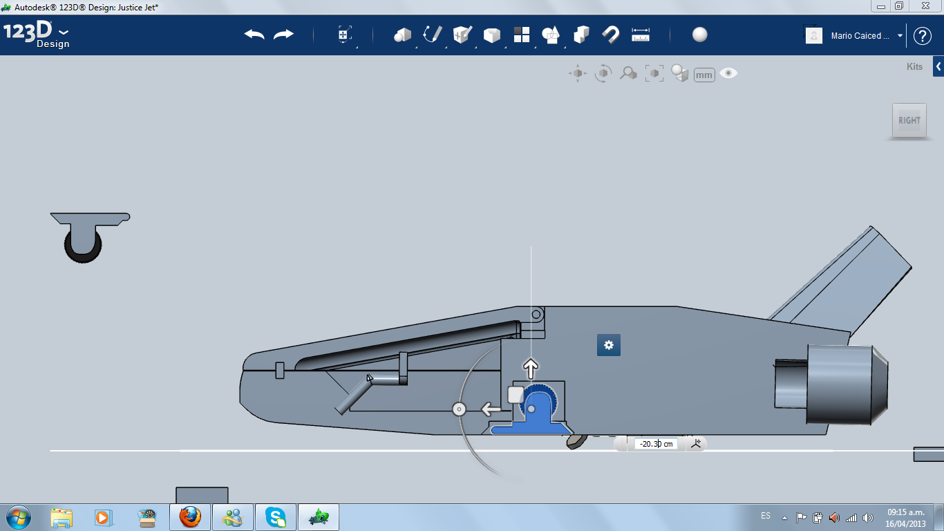
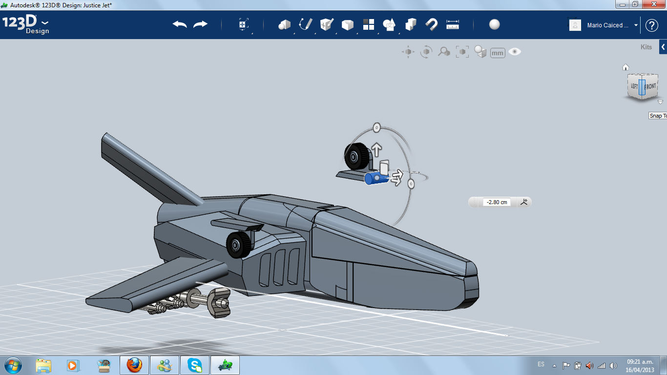
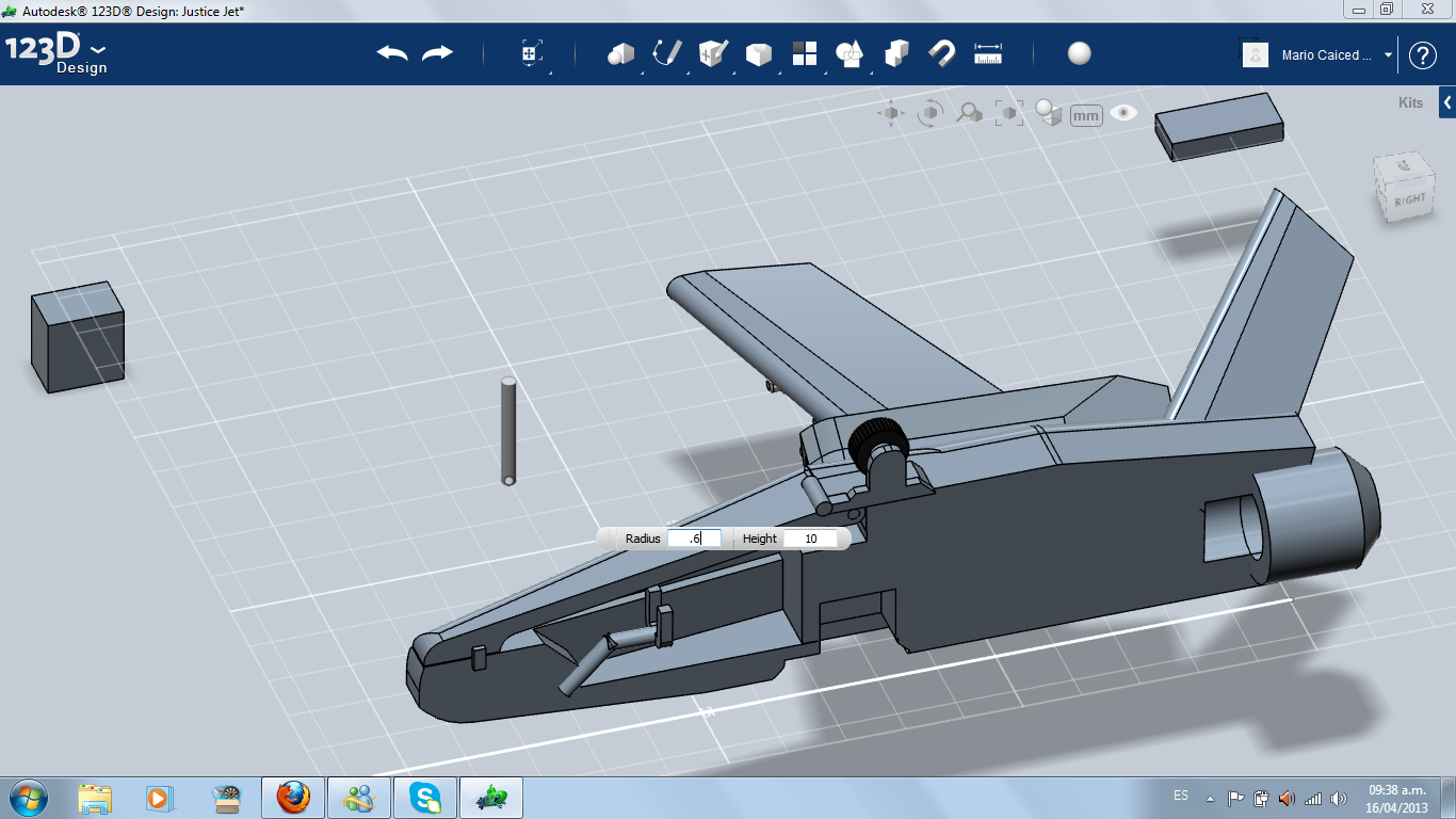
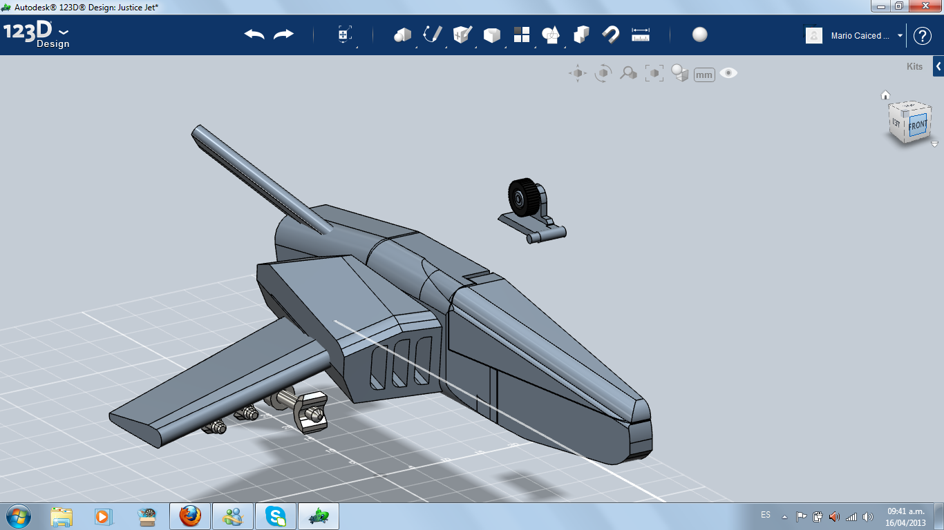
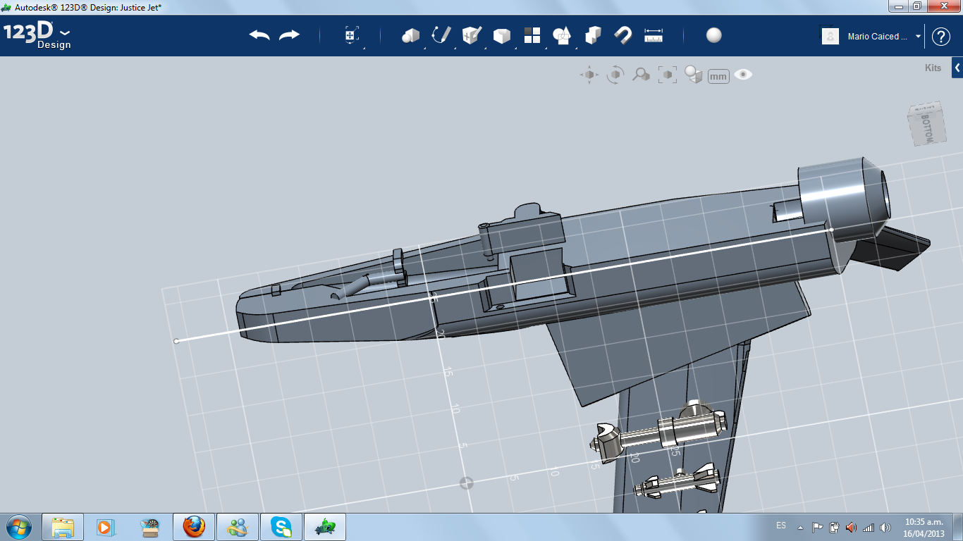
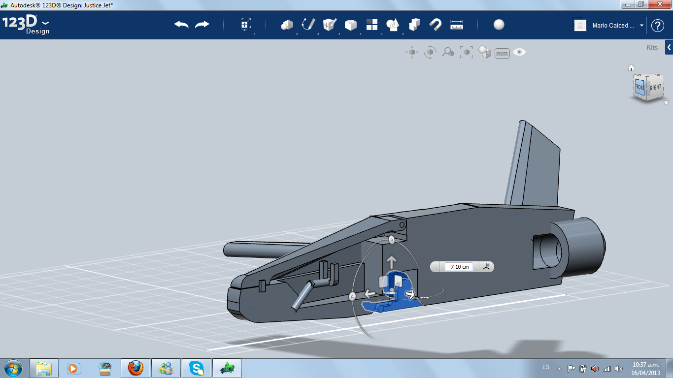
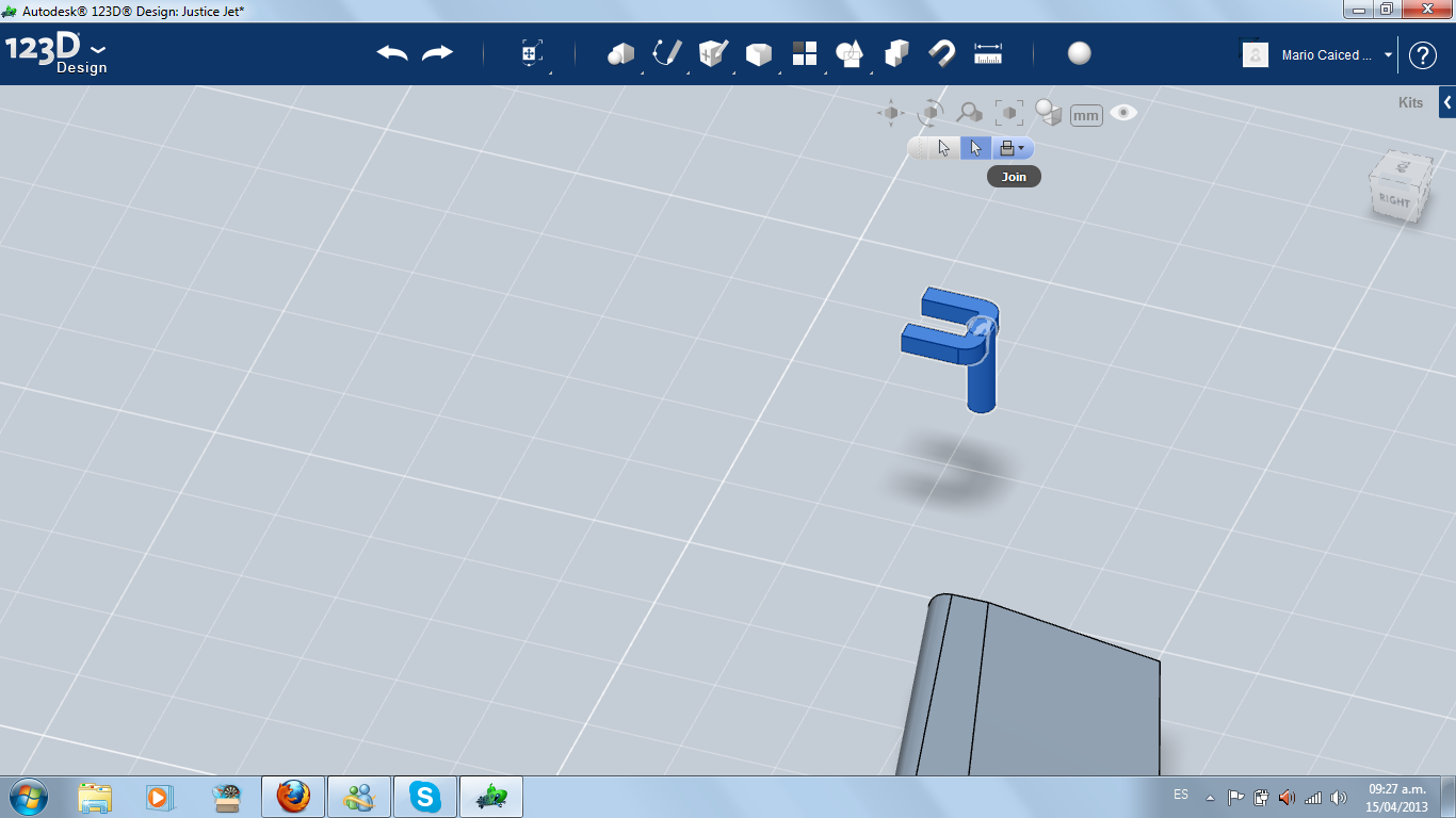
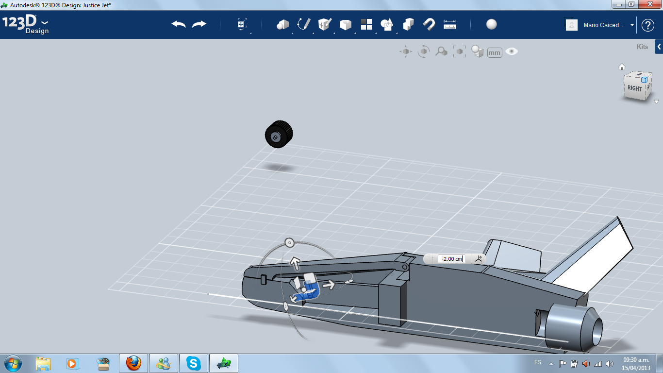
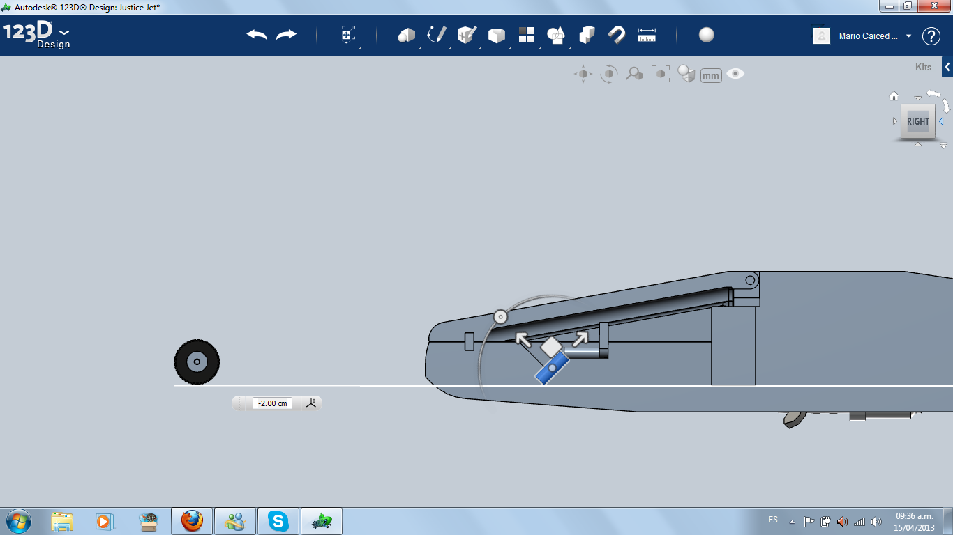
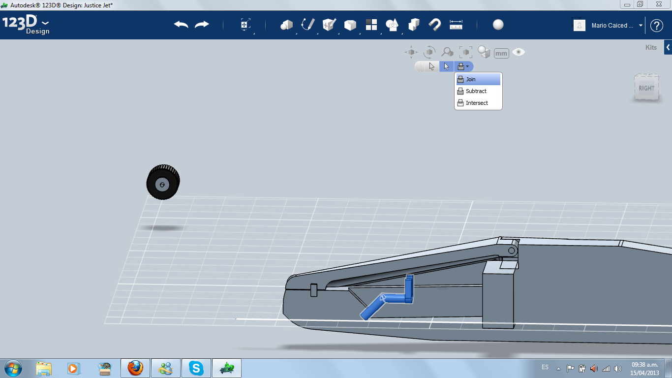
I import a wheel and an axle from my previous 3D printed instructable. Then I made some modifications and created some kind of holder for the wheel, with a flat side for matching with the rest of the fuselage.
Then, I made a hole in the lower front part of the jet for housing the landing gear, and I made a hinge on a similar way of the cockpit.
Then, I made a hole in the lower front part of the jet for housing the landing gear, and I made a hinge on a similar way of the cockpit.
Landing Gear (side)
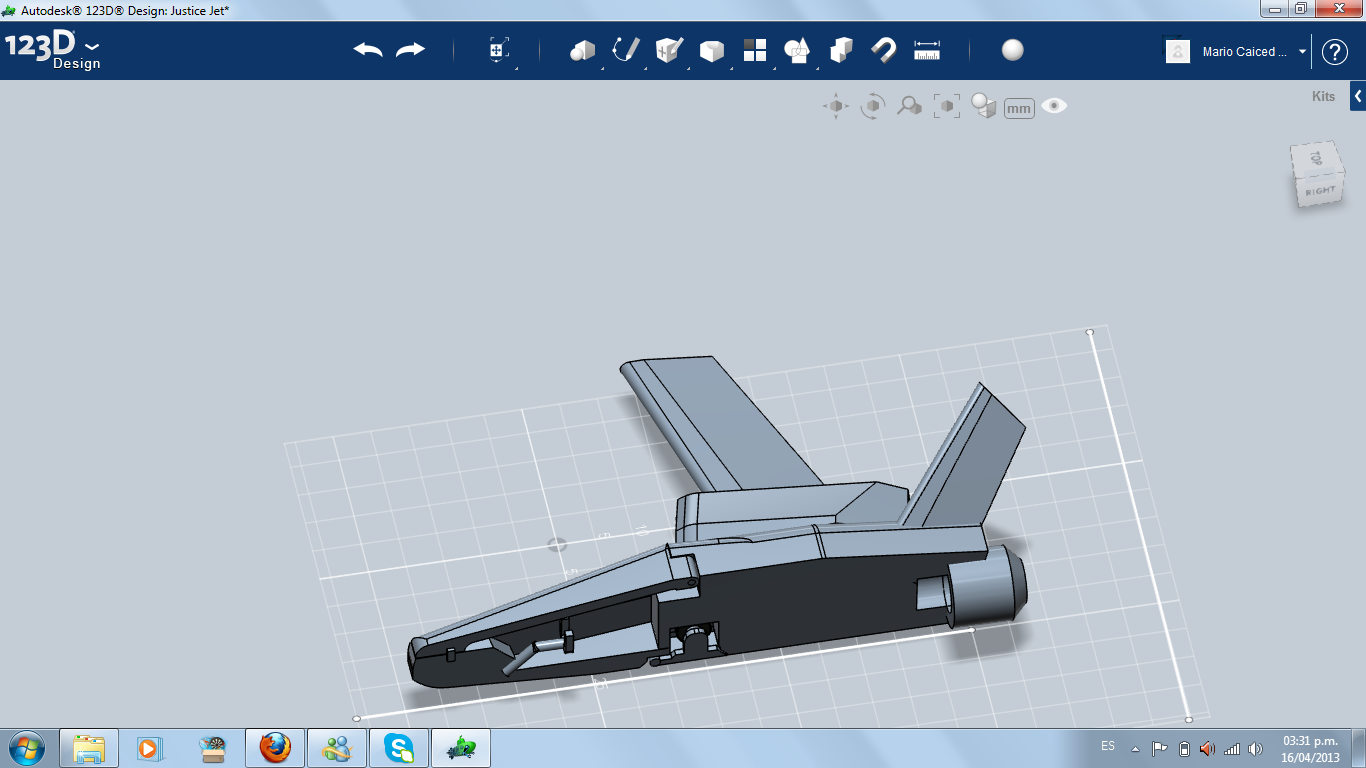
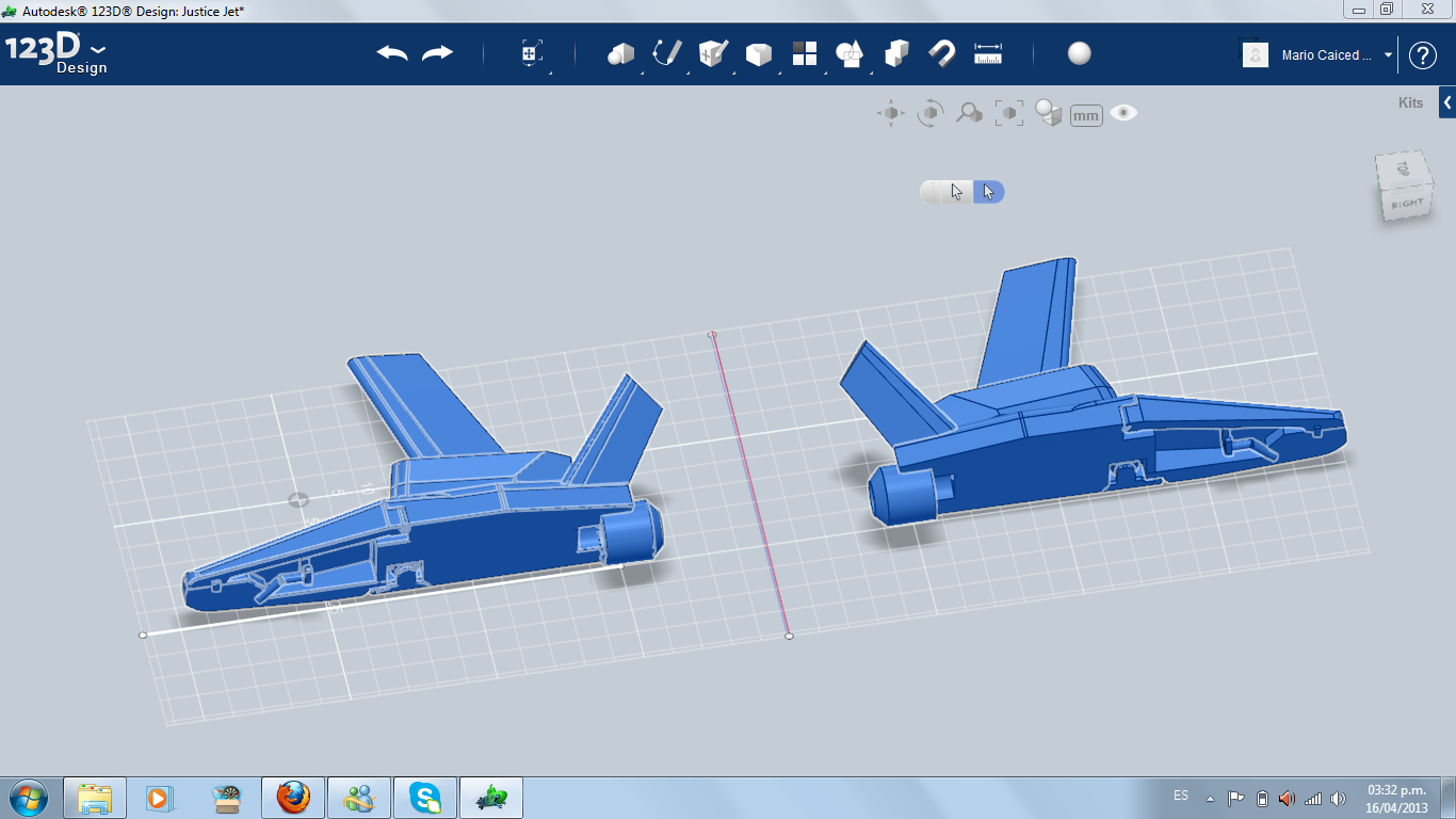
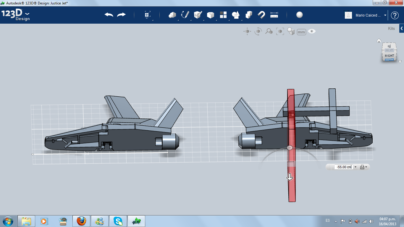
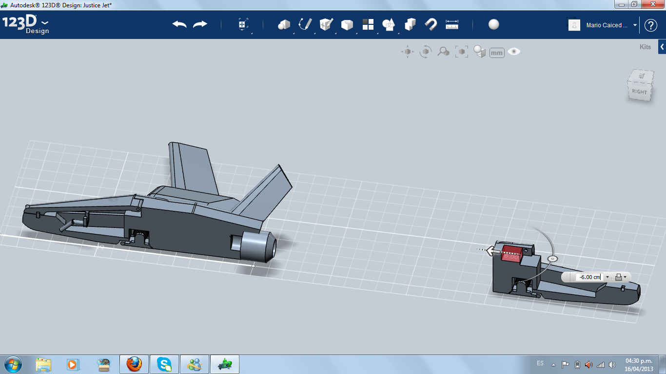
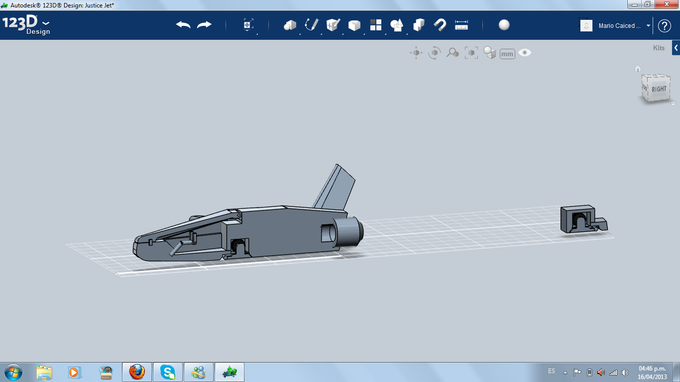
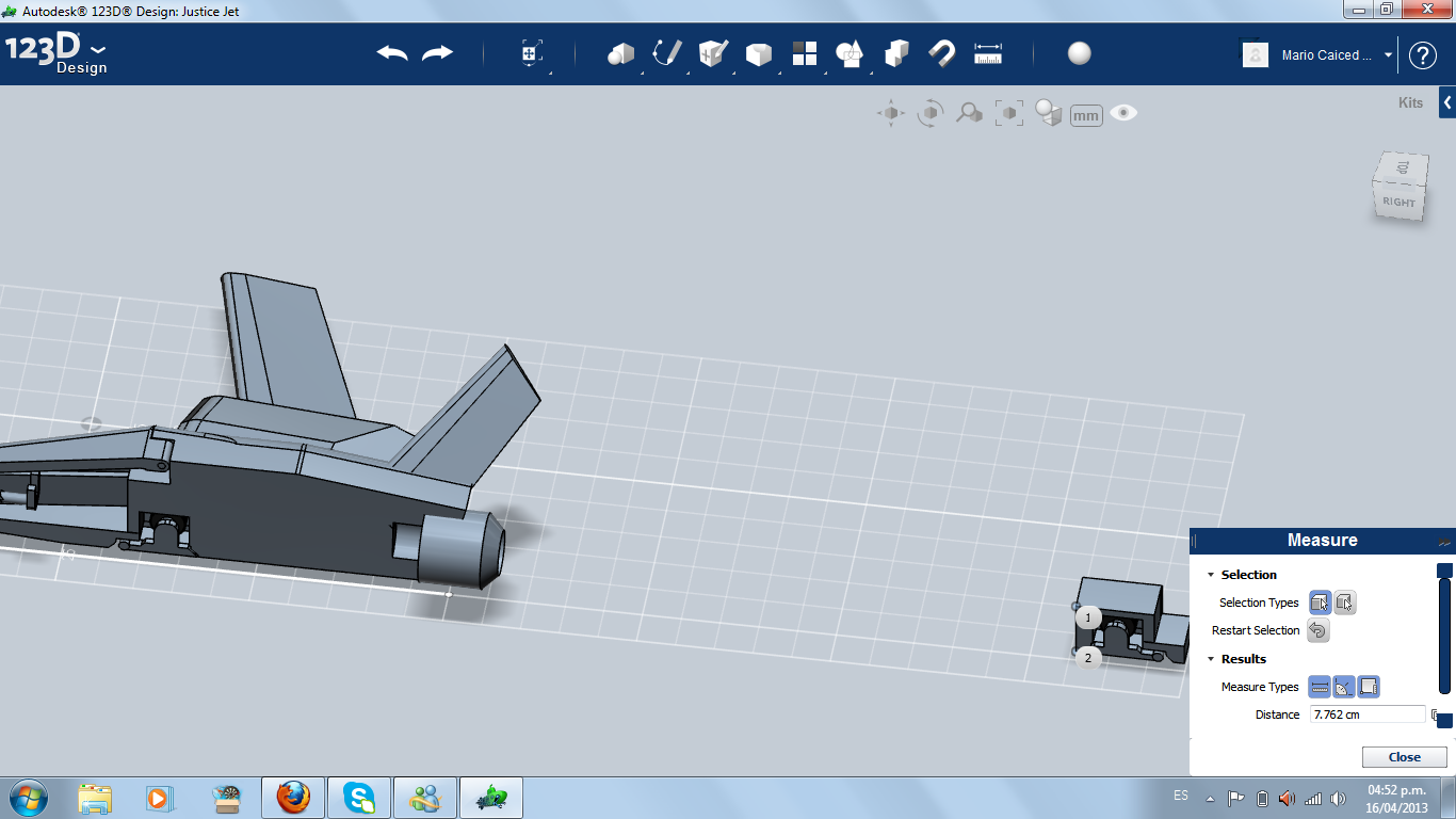
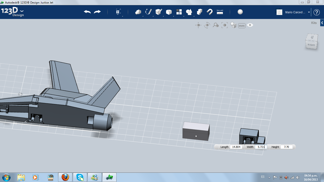
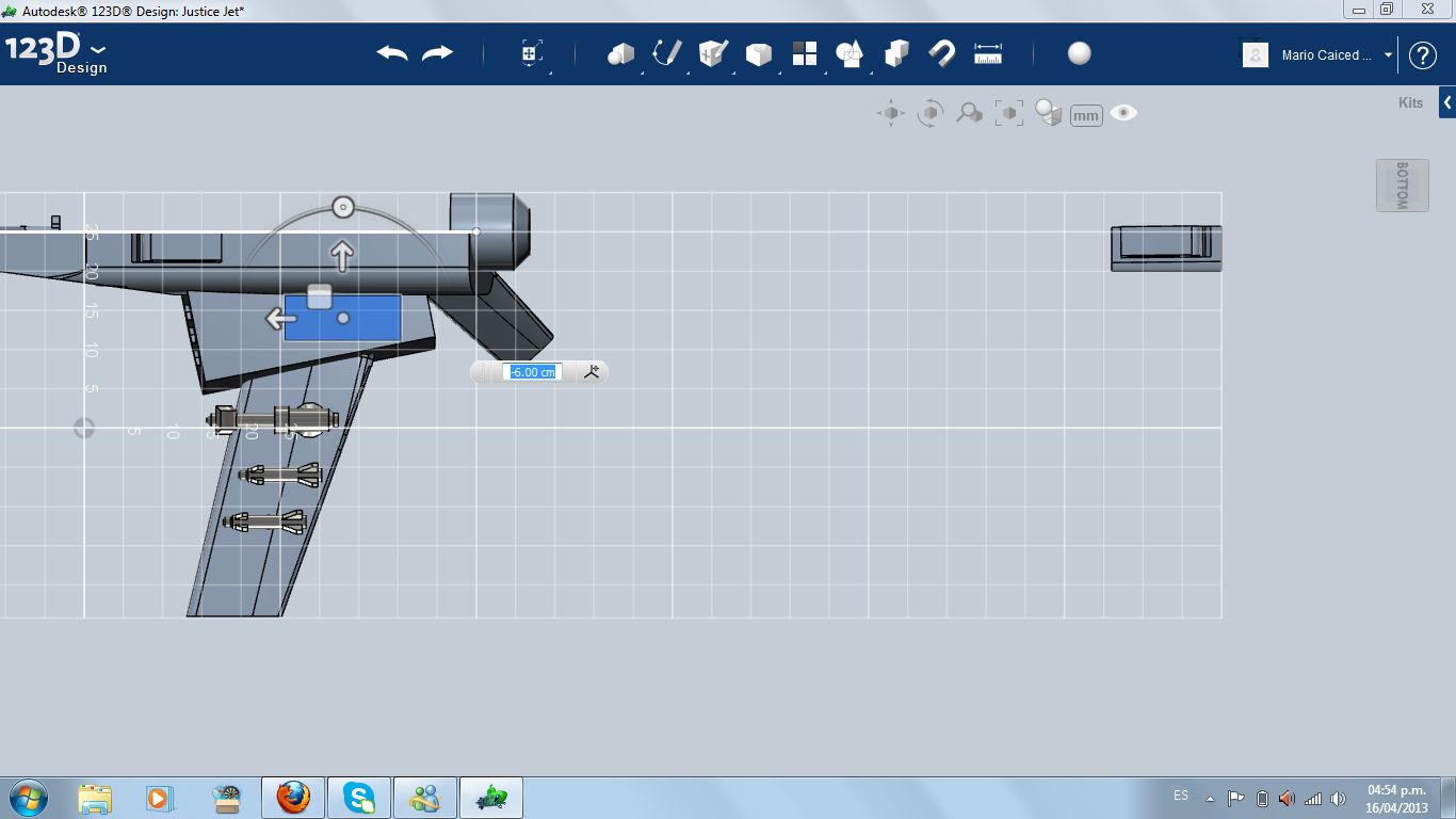
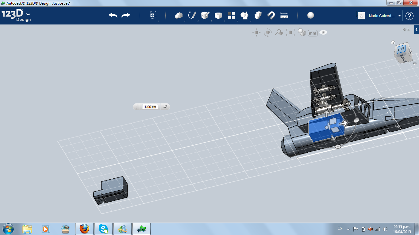
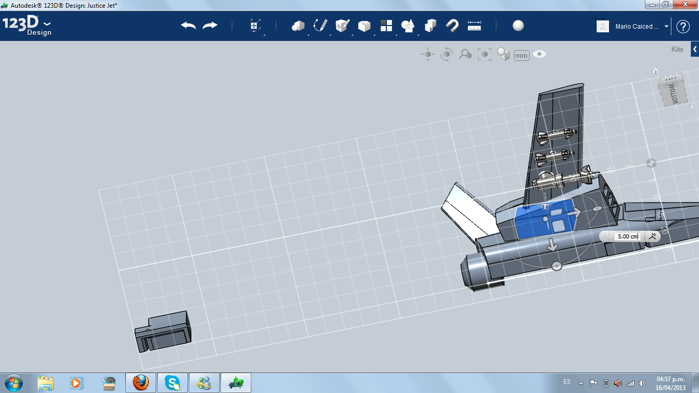
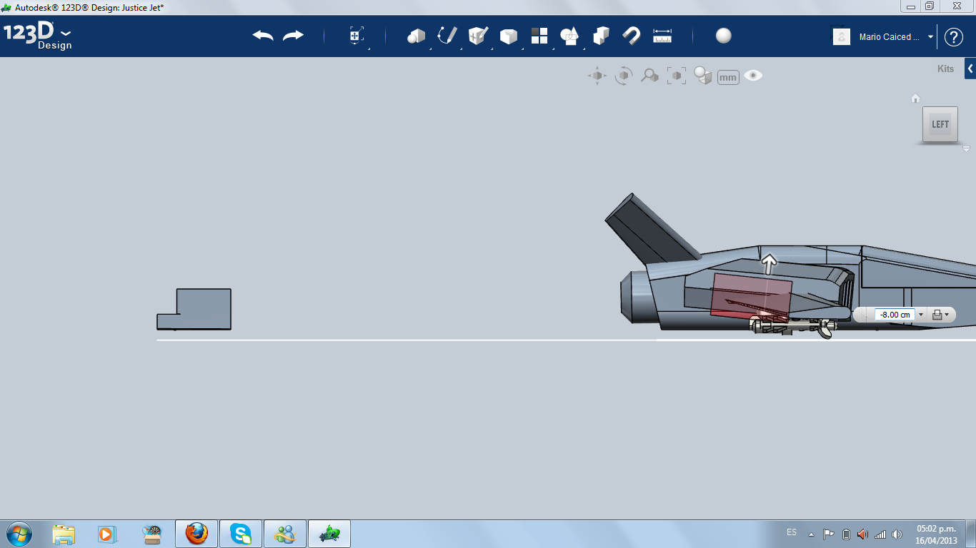
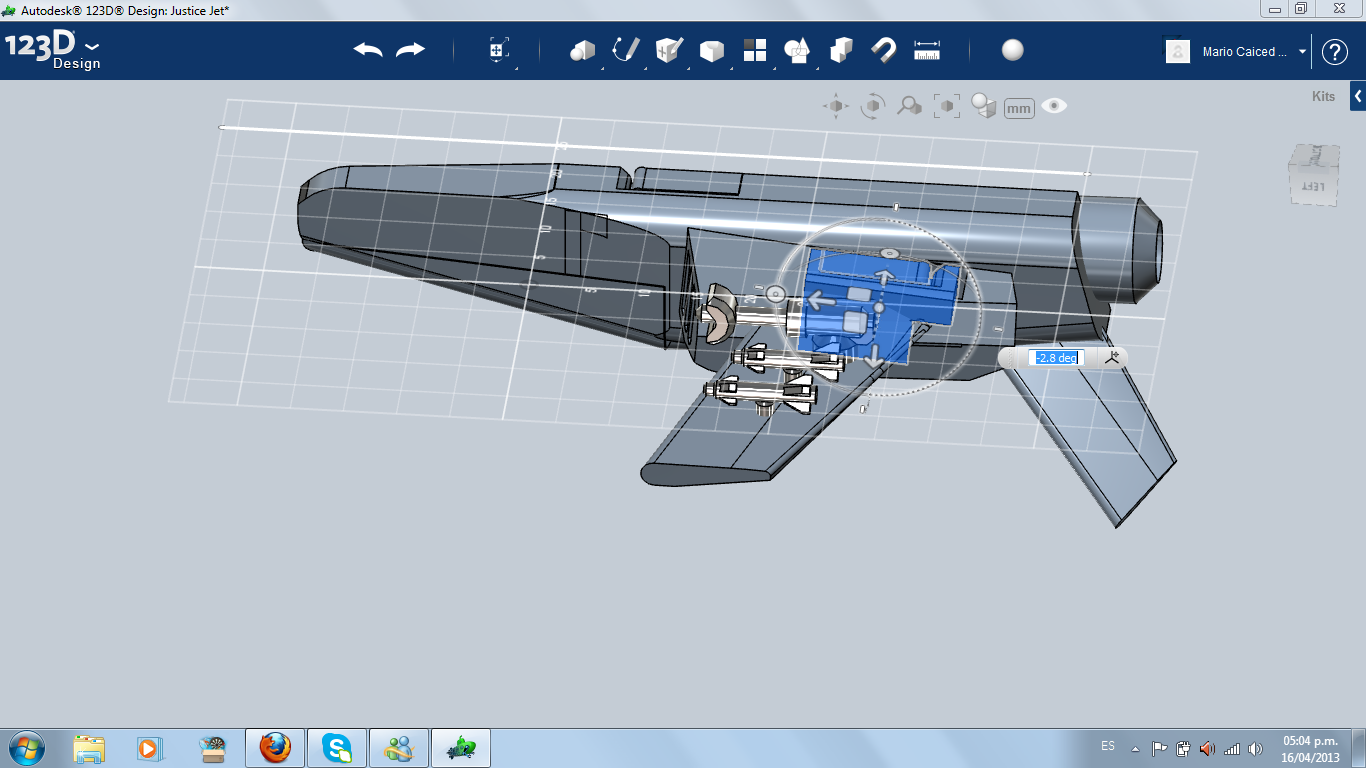
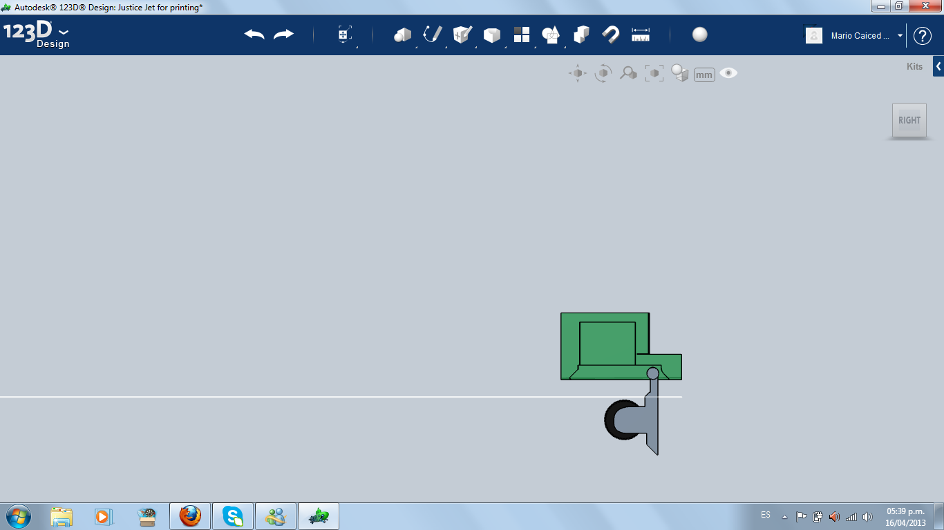
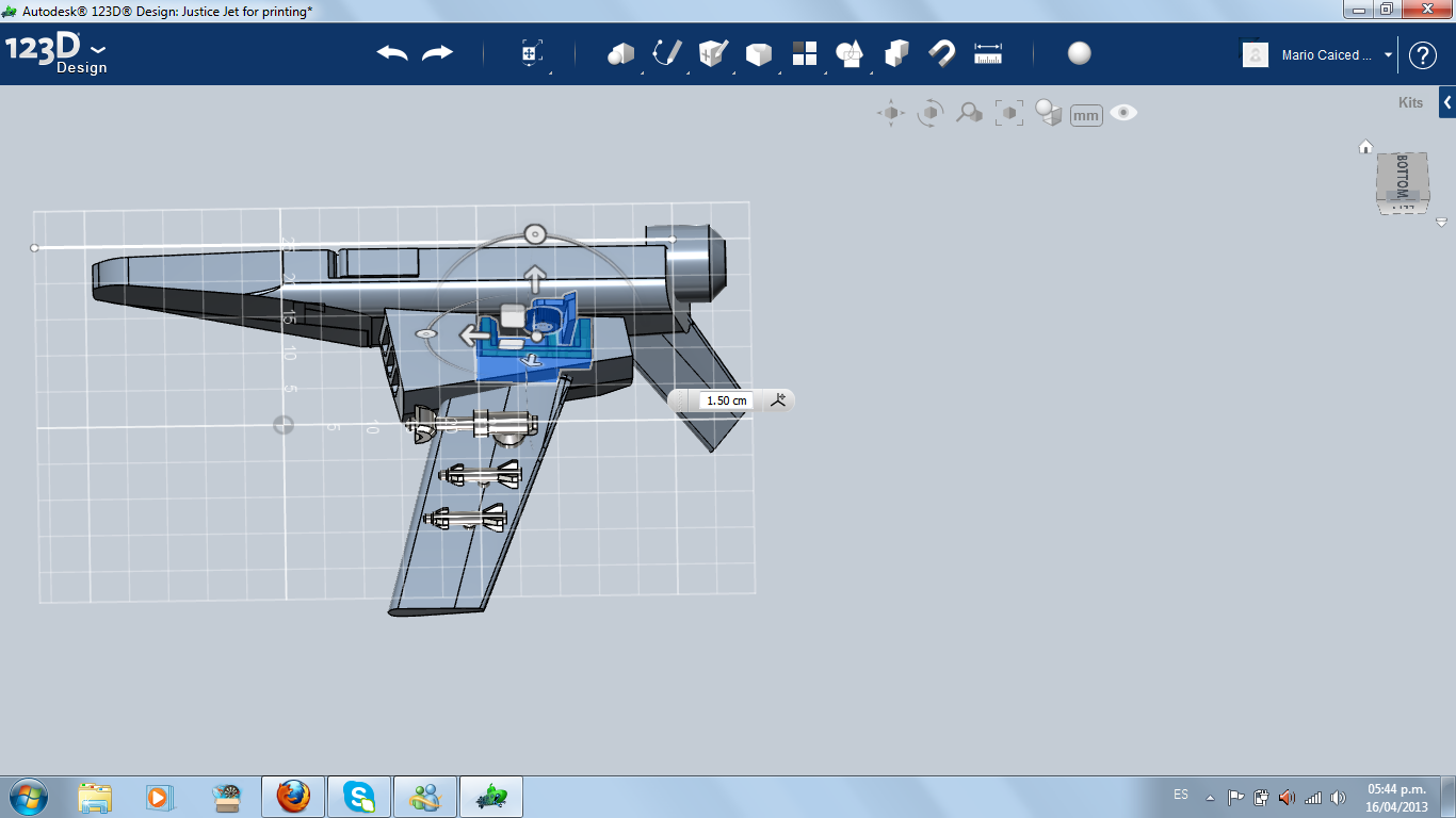
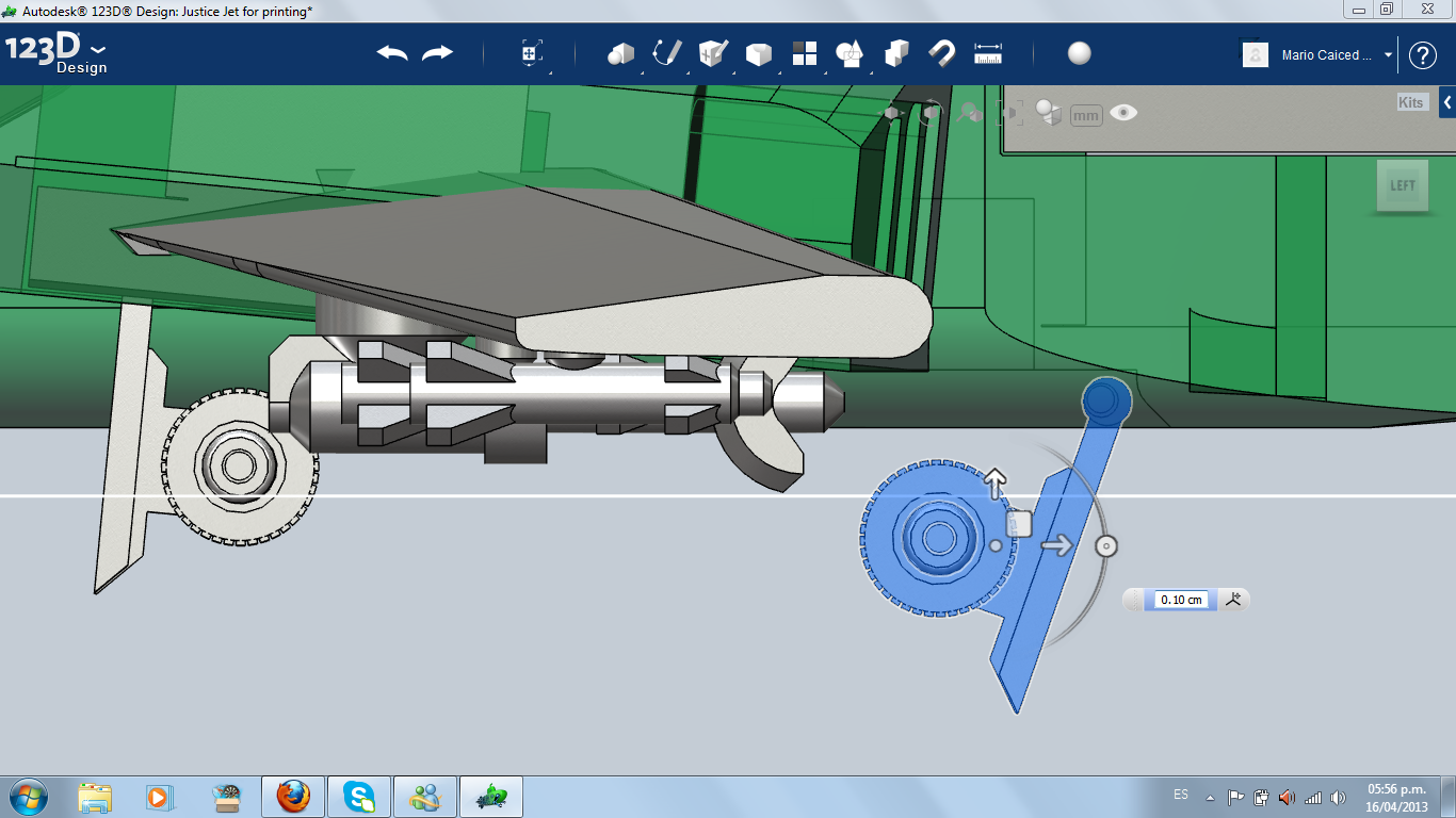
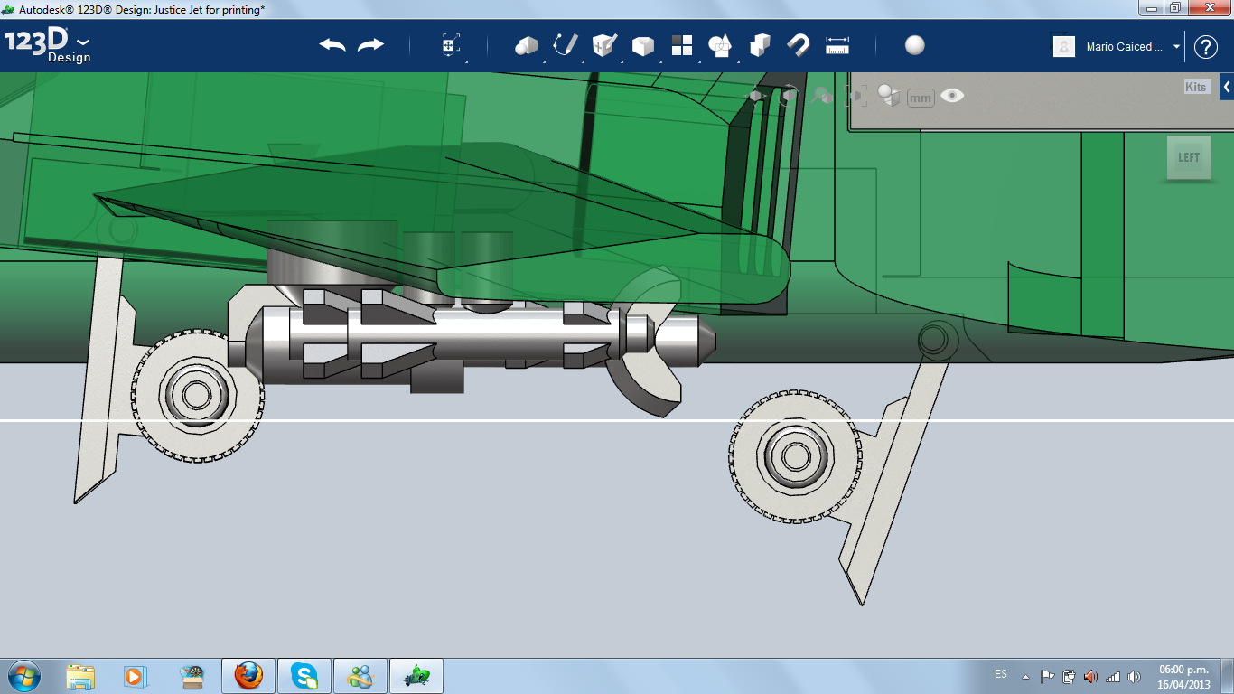
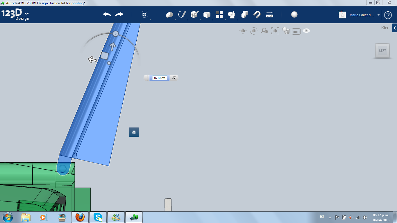
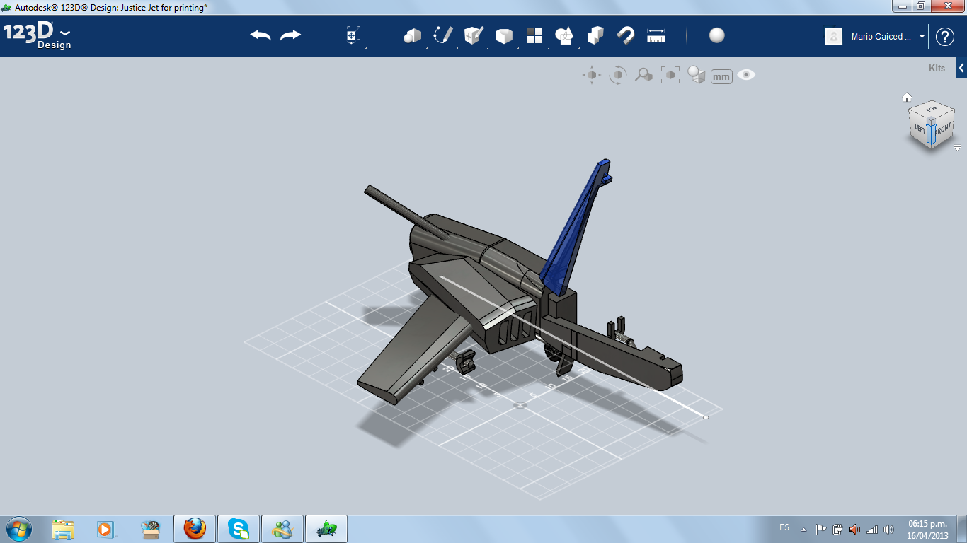
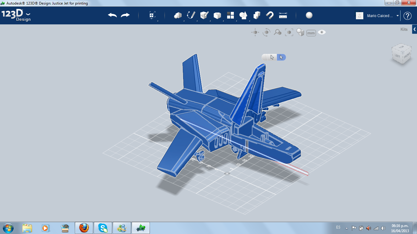
So, I needed to make a landing gear for the side, that opens opposite to the front landing gear. It was a hard job the first time, so I did a curious trick: I make a new mirror of the jet, then I cut everything of the "clone", except the landing gear. Then I installed it in the air intake box. When finished, I make the mirror pattern and get my whole jet.
I completed the model. Next step: 3D printer. But first, I had to open the cockpit and the landing gear for a better printing.
I completed the model. Next step: 3D printer. But first, I had to open the cockpit and the landing gear for a better printing.
3D Printing
