Make a Clock With Fusion 360 and a CNC Machine
by philandmarimanning in Workshop > CNC
2561 Views, 10 Favorites, 0 Comments
Make a Clock With Fusion 360 and a CNC Machine
A quick search of the web doesn't give many clues on how to make a clock face designed with a CAD program. This instructable gives one method to align the numbers on the clock face. I am hoping that in the comments others will add better solutions. Our 8th grade students at Rift Valley Academy in Kenya www.rva.org make this for a woodtech class project.
Supplies
Wood, Fusion 360, a clock movement, CNC machine.
Draw the Boundary of Your Wood
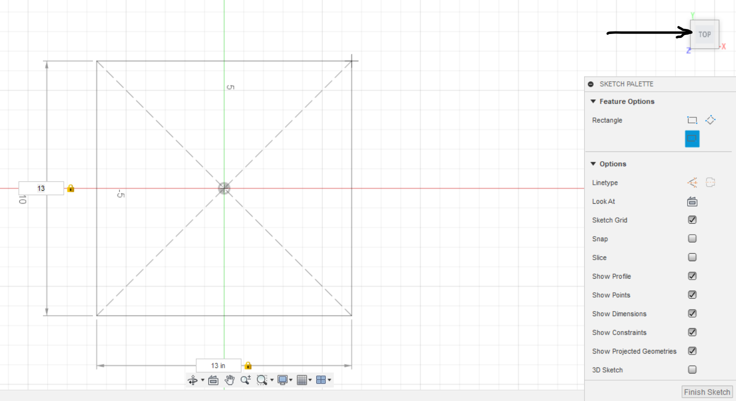
Measure the piece of wood you have or glue up some boards to your desired size. Make your drawing fit your wood. Start a new sketch in Fusion 360 and select center point rectangle to represent the boundaries of your wood. When drawing the rectangle, I have found it easiest to type in the numbers for the size. Use the tab key to select the box to type in the length of the second side. In this example I used a 13 inch center point rectangle and placed it on the plane so that it is visible from the top view.
Insert an SVG File for Your Preferred Clock Shape
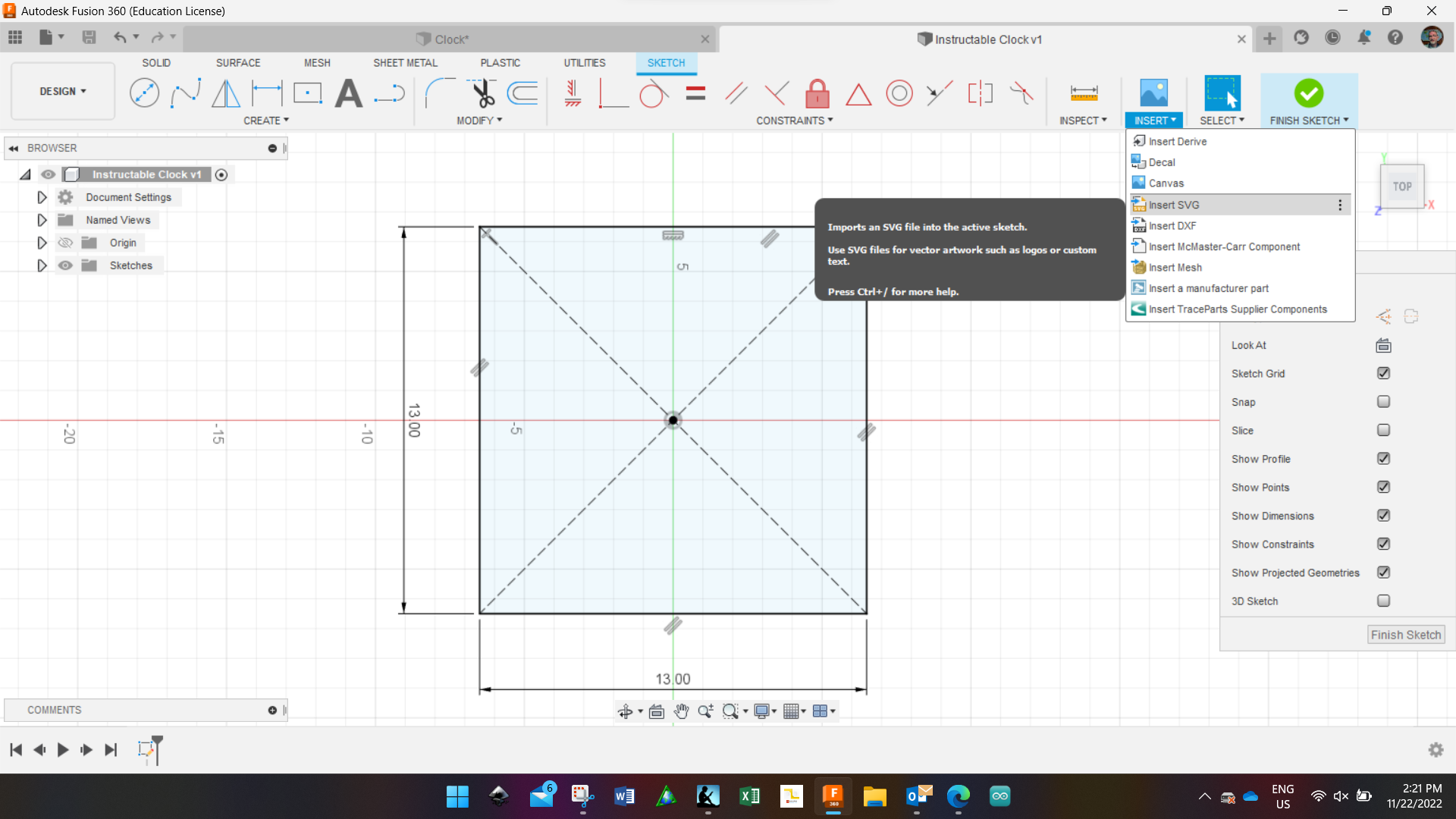
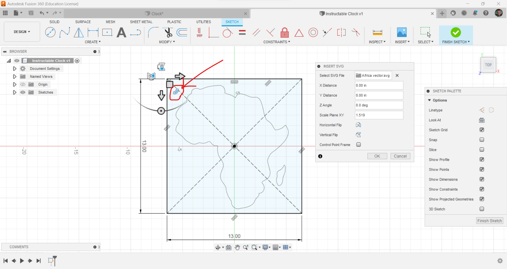
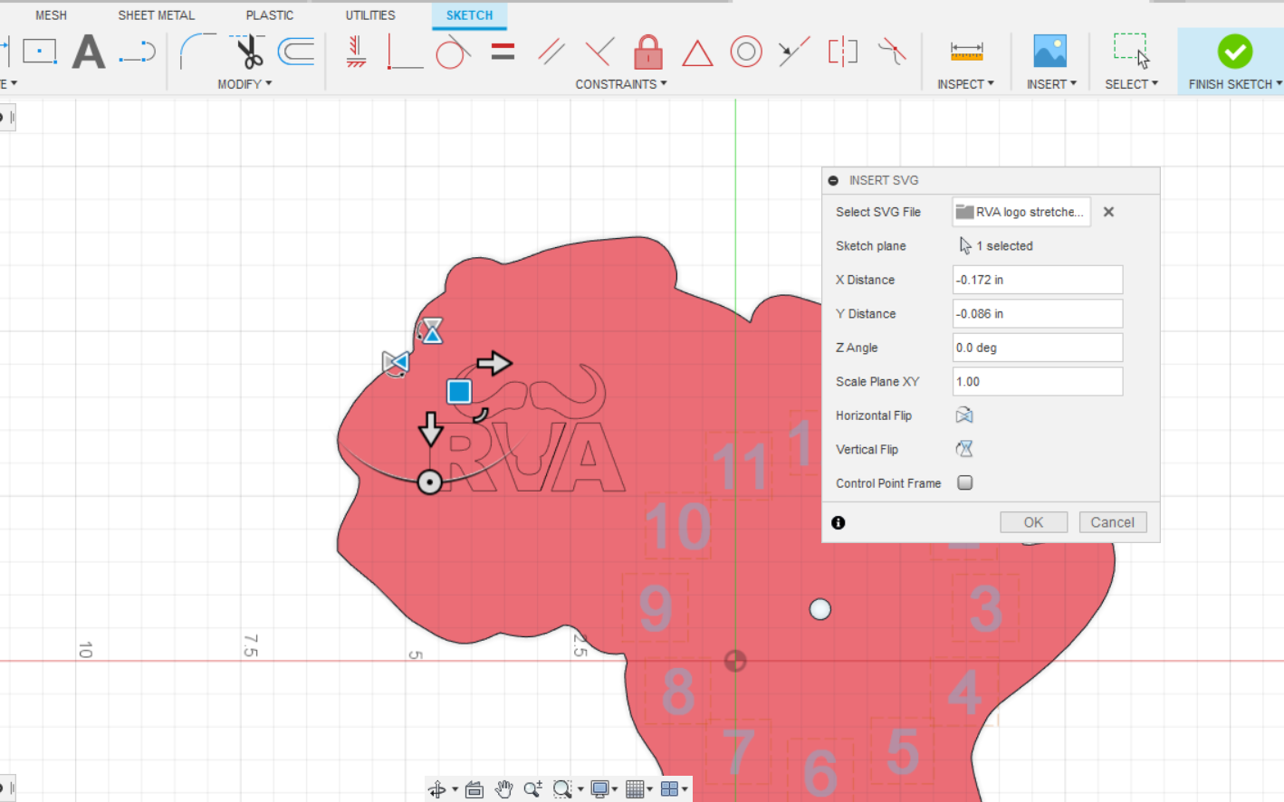
Insert an SVG file that you want for the shape of your clock. Fit it within the boundaries of your rectangle board size sketch. One of the hardest parts of the project is to find a good SVG file. Plan to spend some time searching the web for an SVG file that works for you. Not all SVG files work well. They may have been converted from another format and have some missing data. If the file doesn't work right away I have found it is best to abandon it and find another. There are many resources on the web to help you convert files and use programs to make an SVG file out of other drawings in programs like Inkscape.
To resize the image once imported select the curved button on the moving command and drag it outwards to enlarge the drawing. Move the image with the square block on the command to fit inside of your boundary. I have not had success in editing the image after I have hit enter to select it. I simply start the insert SVG process again if I don't like the initial results.
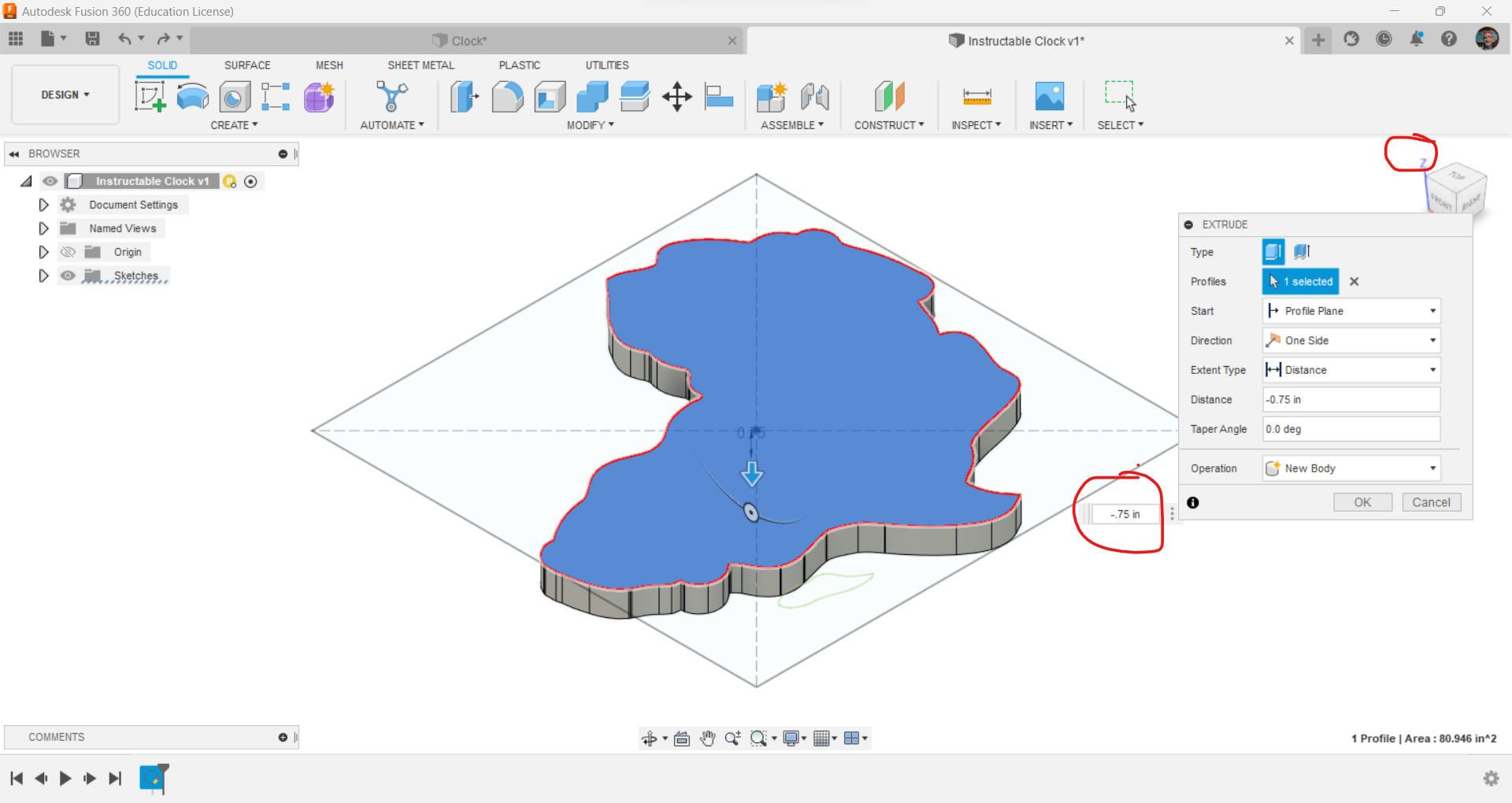
Finish the sketch after you are happy with your drawing. Make your clock 3D by using the press/pull command and typing in -.75 inches (or whatever thickness your wood is). Tip your drawing into a 3D view by selecting the house that appears when you hover your mouse over the viewcube.
Draw the Clock Face
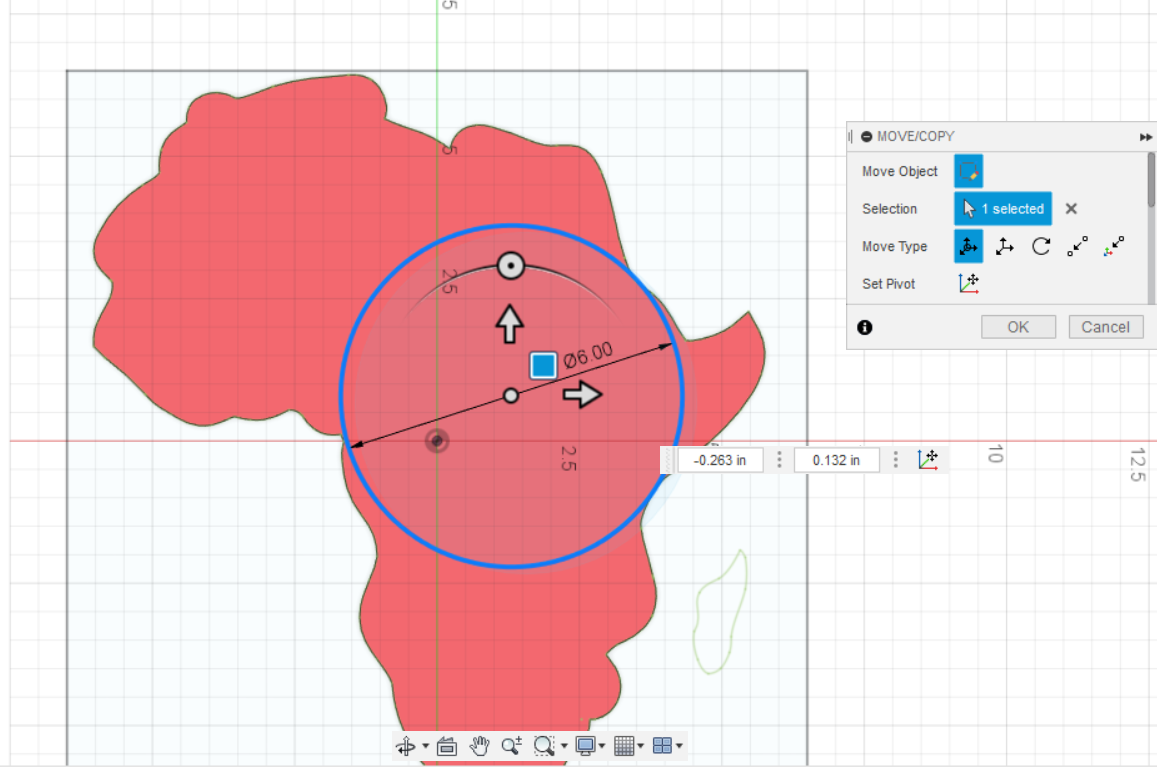
- Create a new sketch making sure to place it on the top of your clock board.
- Draw a circle as large as you can inside of your clock boundary. You'll likely have to move it around to place it where you want. Use the menus to get to the Move/Copy command or simply select your circle and hit the M key on your keyboard to bring up the Move menu.
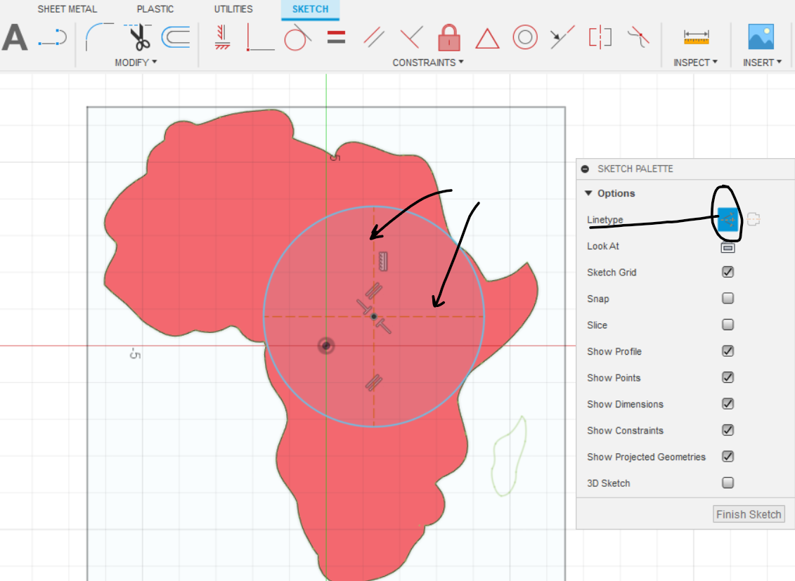
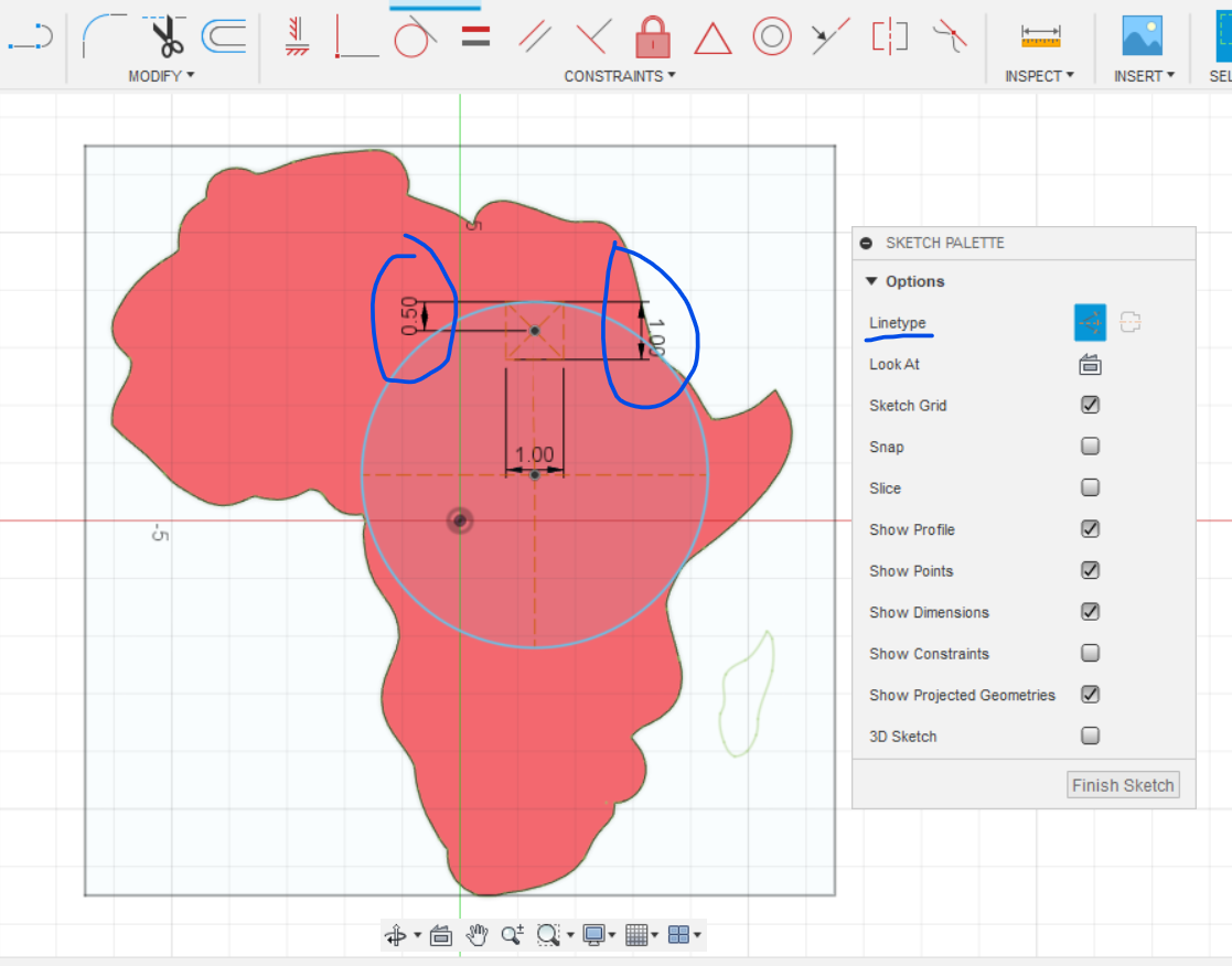
- Draw construction lines to help you orient your numbers. Start at the center and make sure that you are drawing them at 90 degrees to each other.
- Draw a .5 inch line from the edge of the circle inward to orient your number box. Then draw a 1 inch center point rectangle using that point you just made as the center.
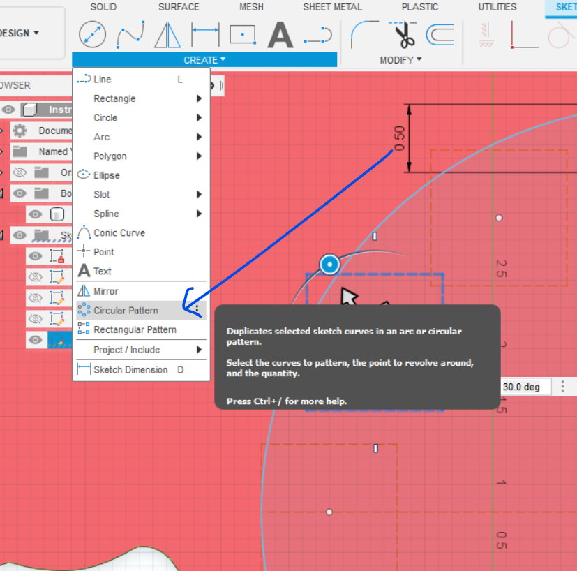
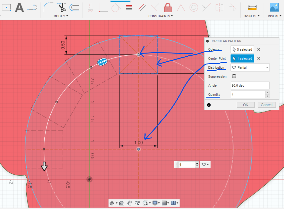
- In the Create menu select "Circular Pattern."
- Select, "Partial Pattern." This will save us some time later as otherwise you will need to align 8 squares instead of just 2.
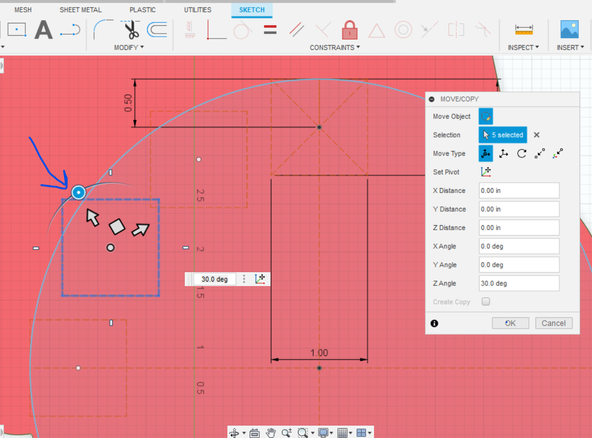
- Select the center point of the box you want to turn (either the 10:00 or 11:00 positions) and then select the "Move" command or hit M on the keyboard. When the menu comes up select the 4 sides of the box you want to turn. Turn the box likely 60 degrees or 30 degrees to align it horizontal with your clock face. If you don't select the center point before selecting the move command the box can get anchored on a corner and not rotate at the center.
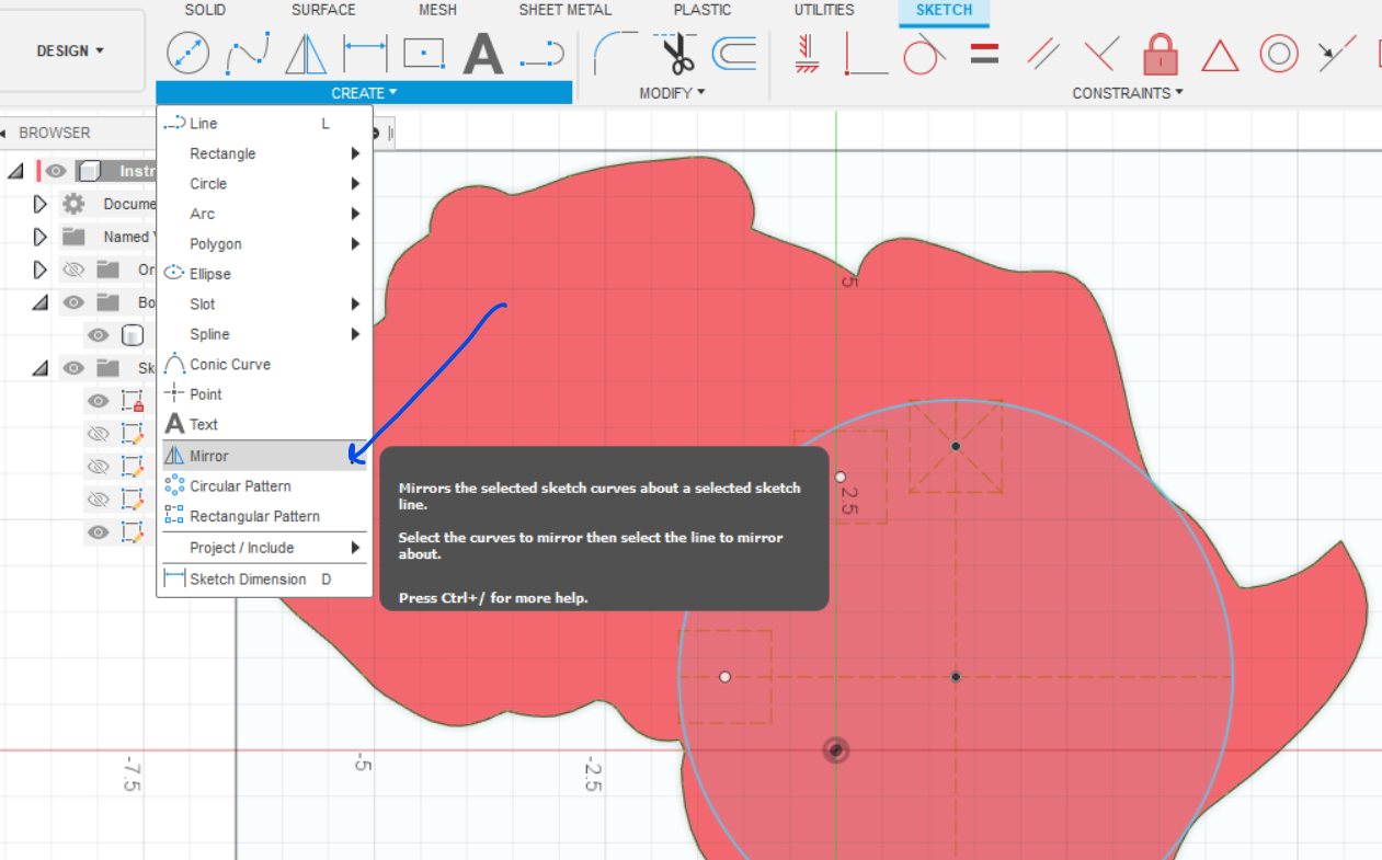
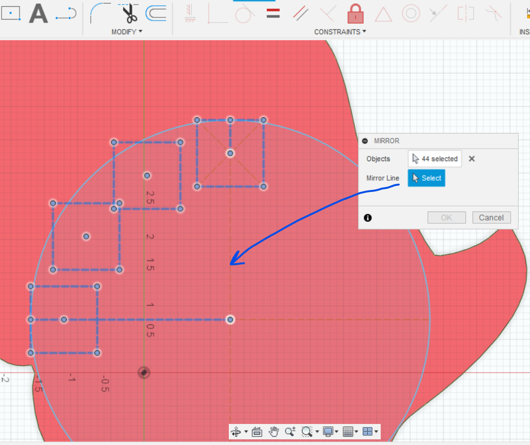
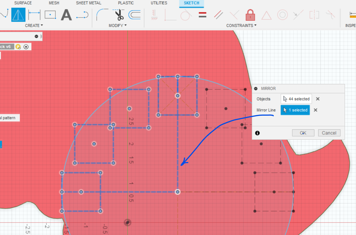
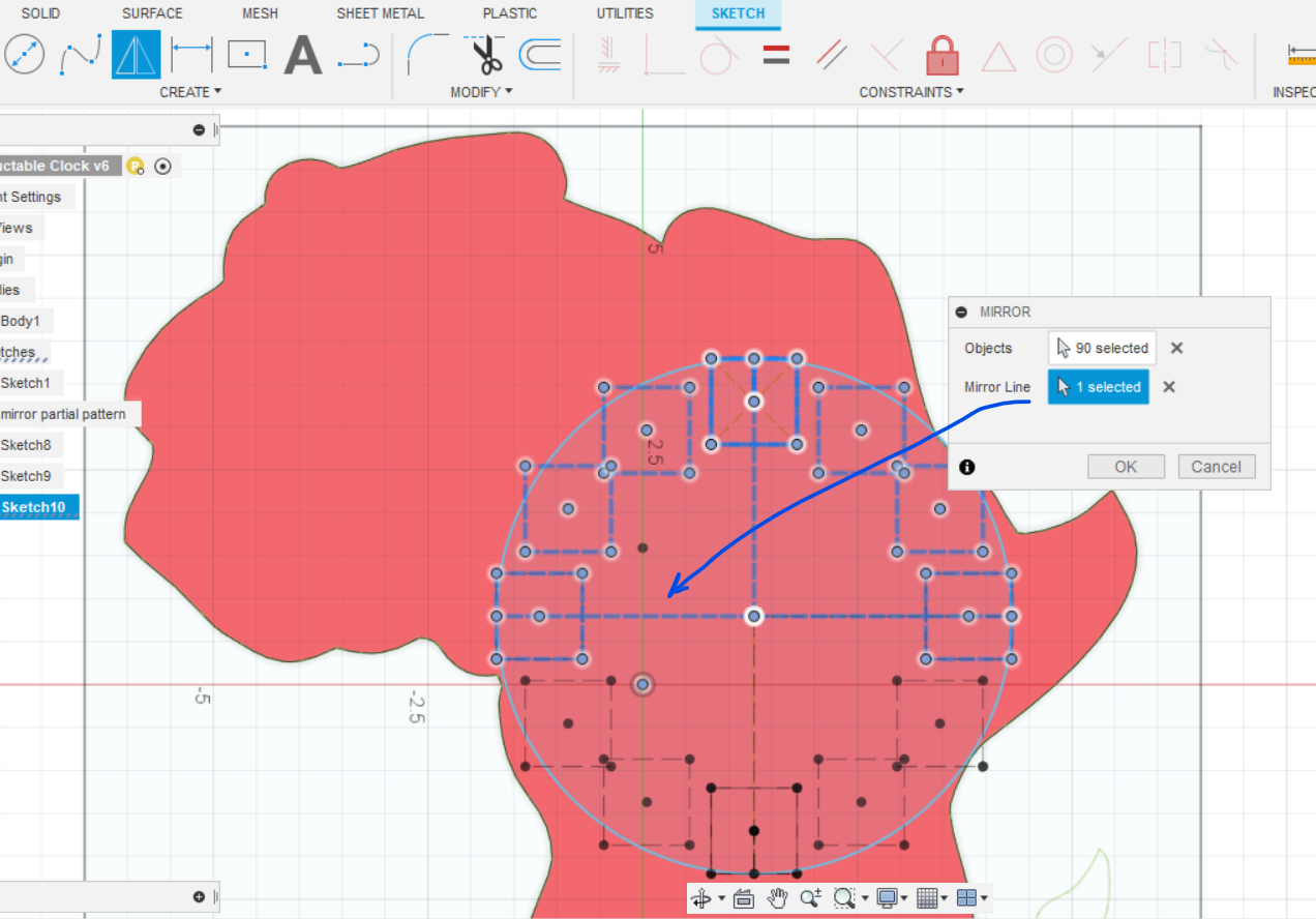
- Once you have the boxes aligned select the "Mirror" command from the "Create" menu. Lasso the 4 boxes but make sure the upright line from the center of the circle is not selected. You can mouse click that line to deselect it from the objects box. Then select that line for the Mirror Line. When you hit Okay you should see your boxes on the other side of the clock. Do this again by selecting all of the boxes and using a horizontal line for your mirror line to get your boxes fully around the clock face. Close your sketch so that you can use this as a template for another clock where you might want to change the font...
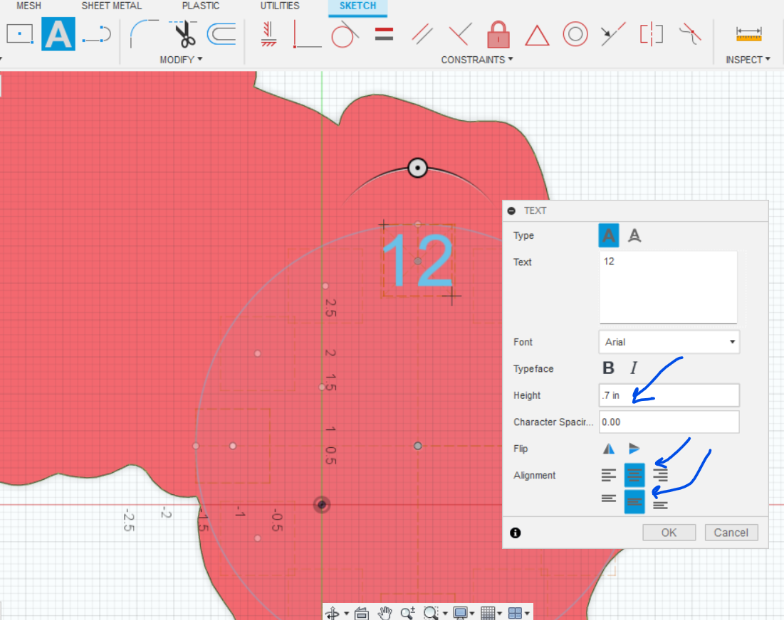
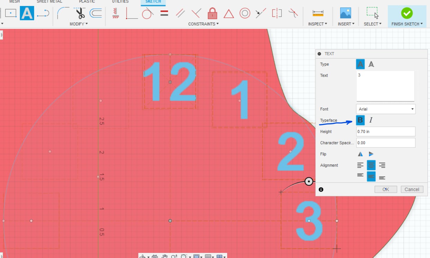
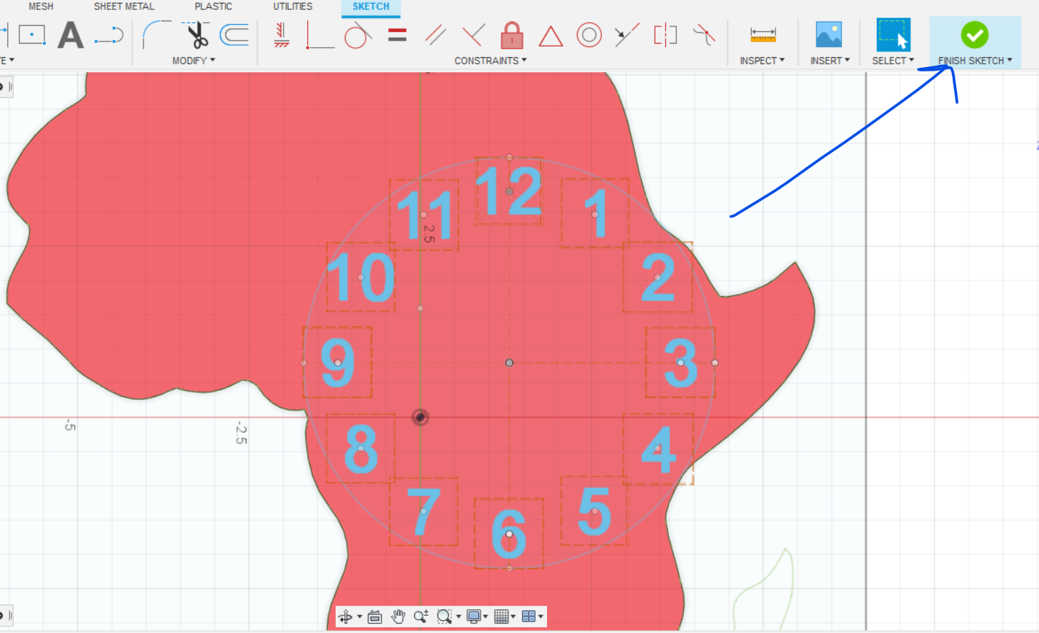
- Start a new sketch on the surface of your clock. Select "Text" from the Create menu. You will need to select a location to put the text. Draw a box the same size as your template you just drew in the 12:00 position. Put 12 in for the text, choose your font, adjust the size, center left to right and top to bottom. You will need to do this for each number. You may want to make it Bold in order for it to engrave deeply in your wood. When you have all of your numbers on select, "Finish the Sketch."
Add a Logo or Text
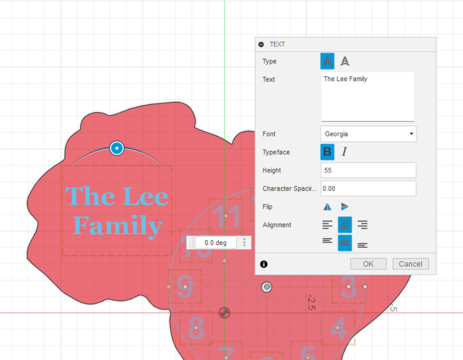
Personalize your clock by inserting an SVG file to put a picture on your clock or add some text.
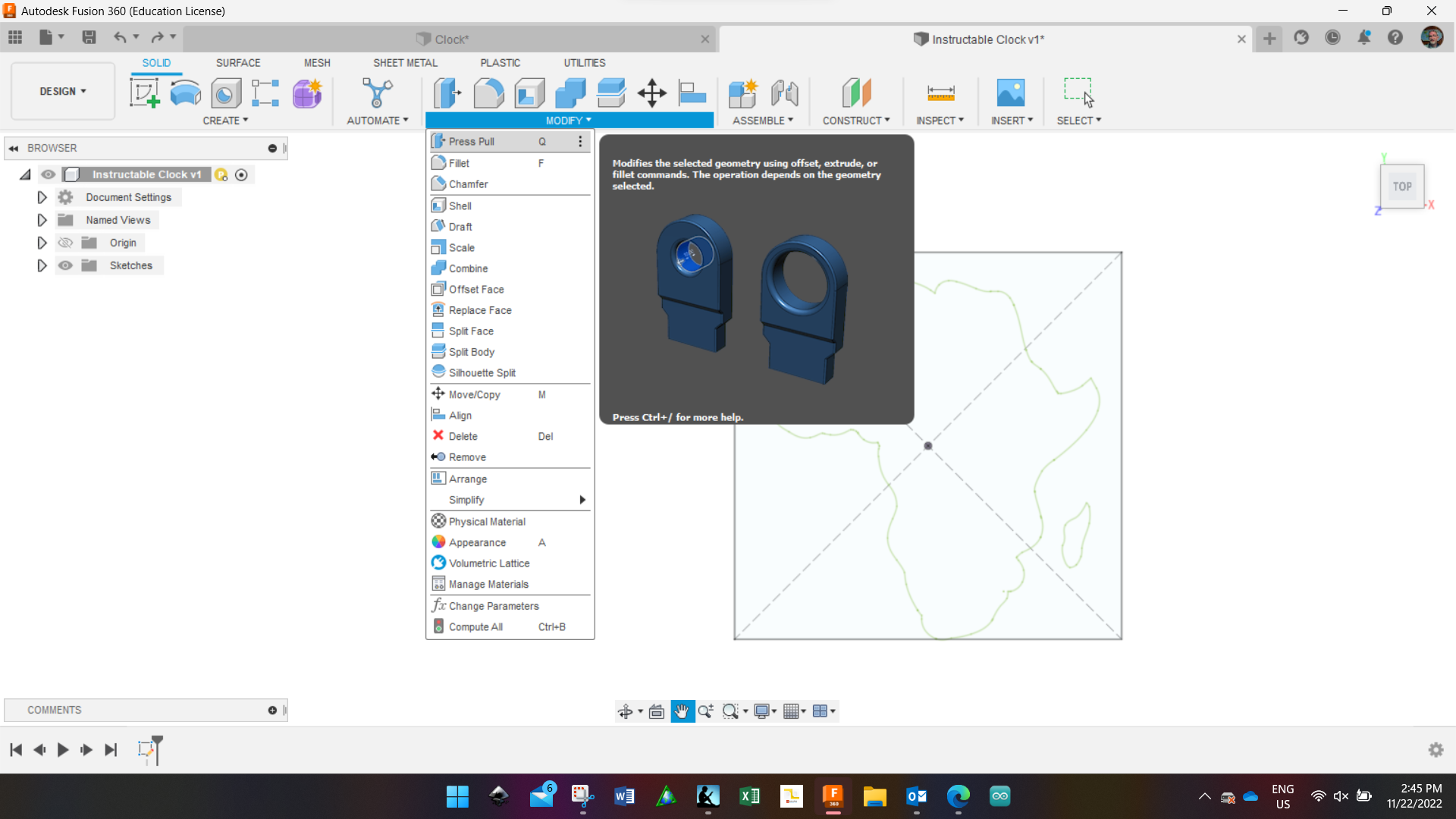
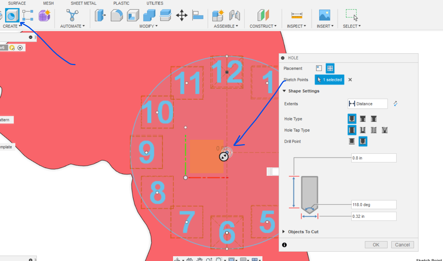
Bore a Hole for the Clock Movement
Inset the Clock Movement in the Back of the Clock
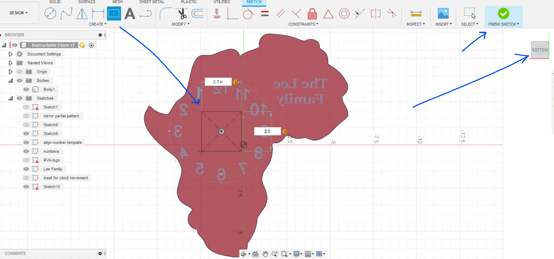
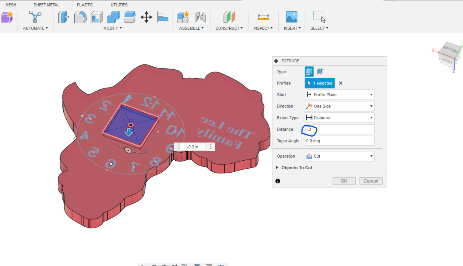
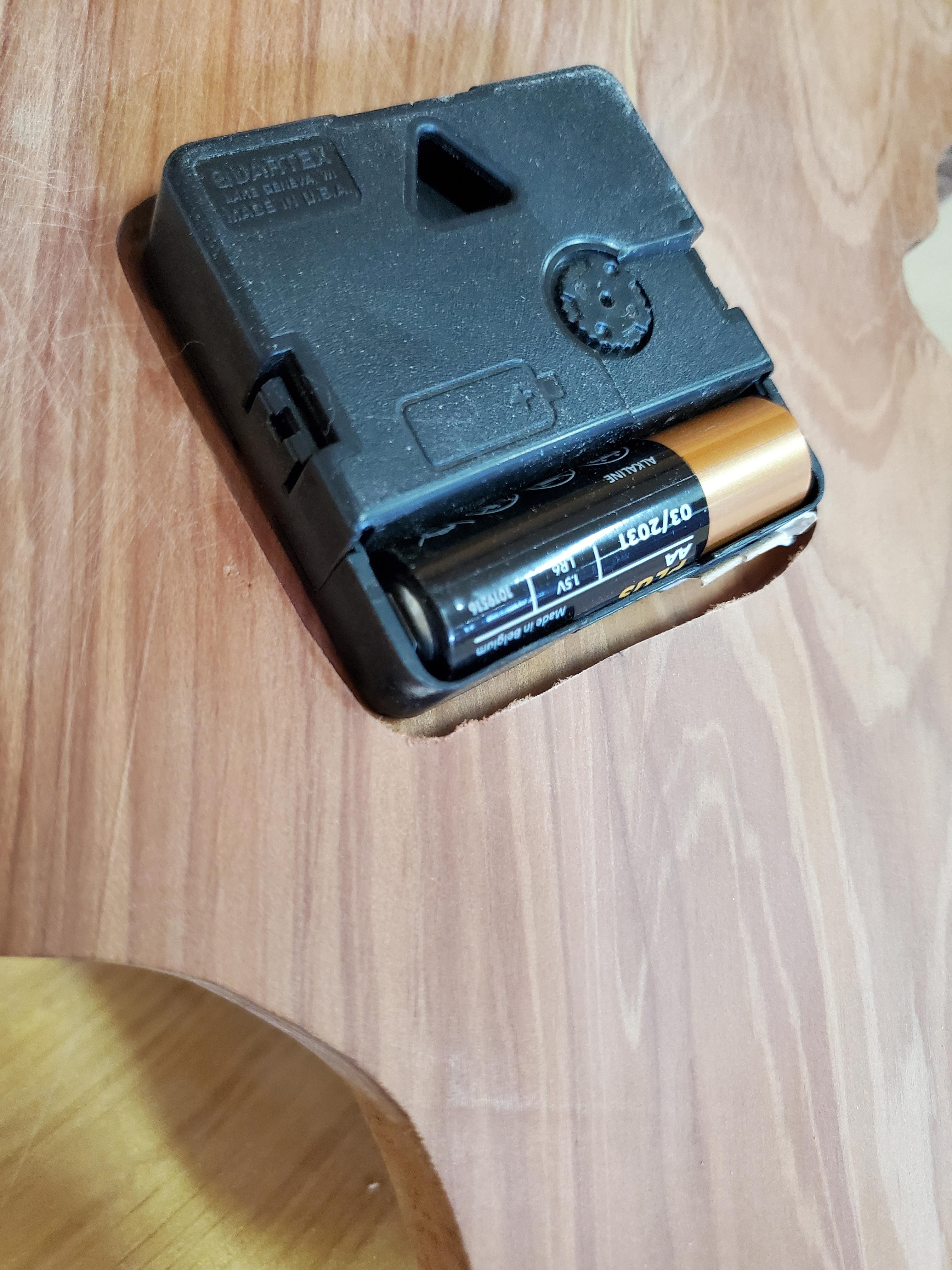
Flip your clock over by using the view cube. Create a sketch on the back of the clock and make a center point rectangle with the center as the hole for the clock movement. Our clock mechanism is about 2" square so make your inset 2.3" to give it some extra clearance. Finish the sketch and use the press pull command to inset the box into the back of the clock deep enough that the shaft of the clock movement will stick through the front with enough distance to thread the nut onto it. Save your work.
Manufacturing
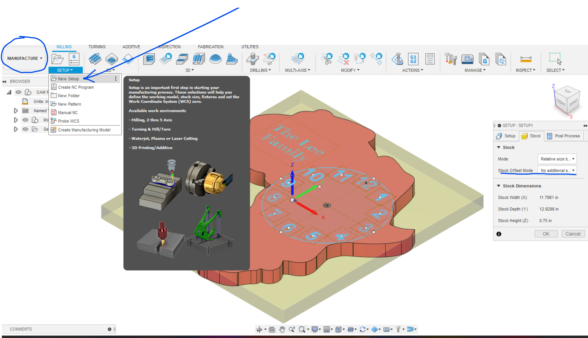
- You have been working in the Design menu and now you will switch to the Manufacturing menu in the top left drop down box.
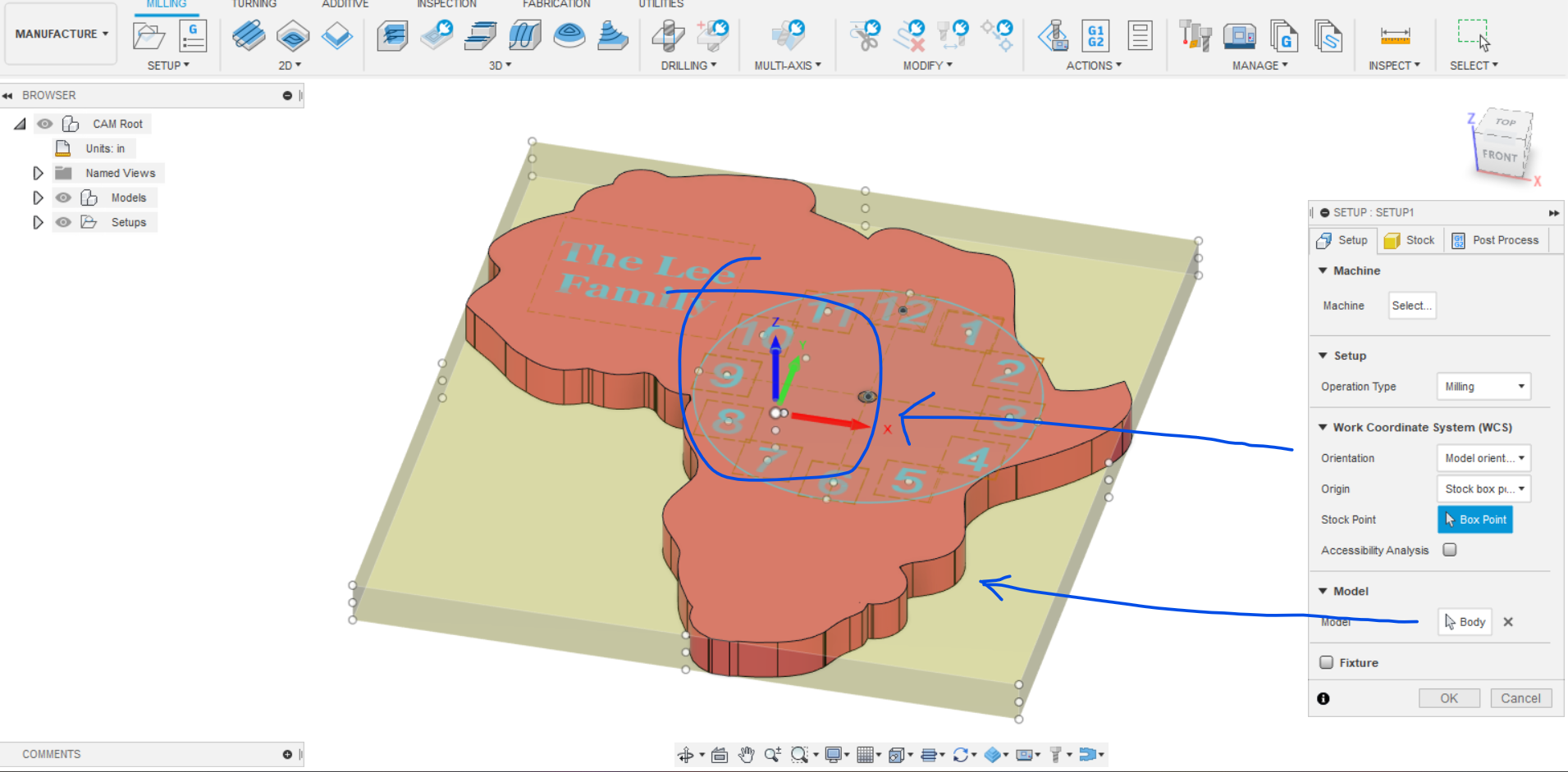
- In the SETUP menu select new setup. Describe your project in the setup menu such as "No Additional Stock" in the stock menu. Verify that your project is oriented correctly with Z pointing up (for our CNC machine's configuration). Verify the direction of the X and Y axis so that you clamp your board in the correct orientation on the table. Save your setup.
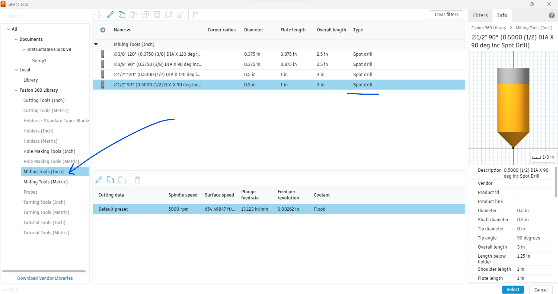
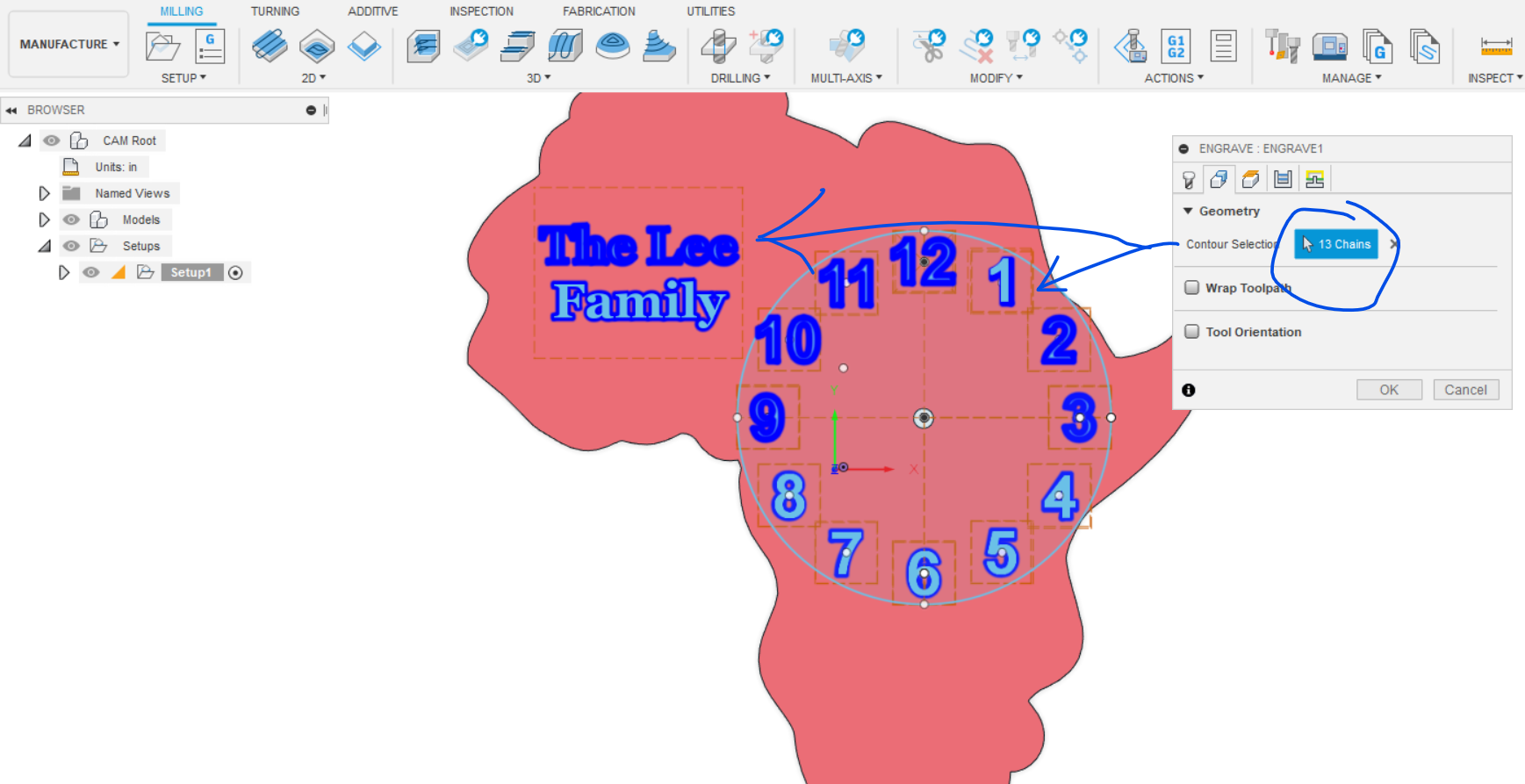
- Select ENGRAVE from the 2D menu. Choose your tool. The 1/2 inch 90 degree spot drill in Milling Tools Inch is the same as our V router bits. Select your numbers and logo or text that you want to engrave.
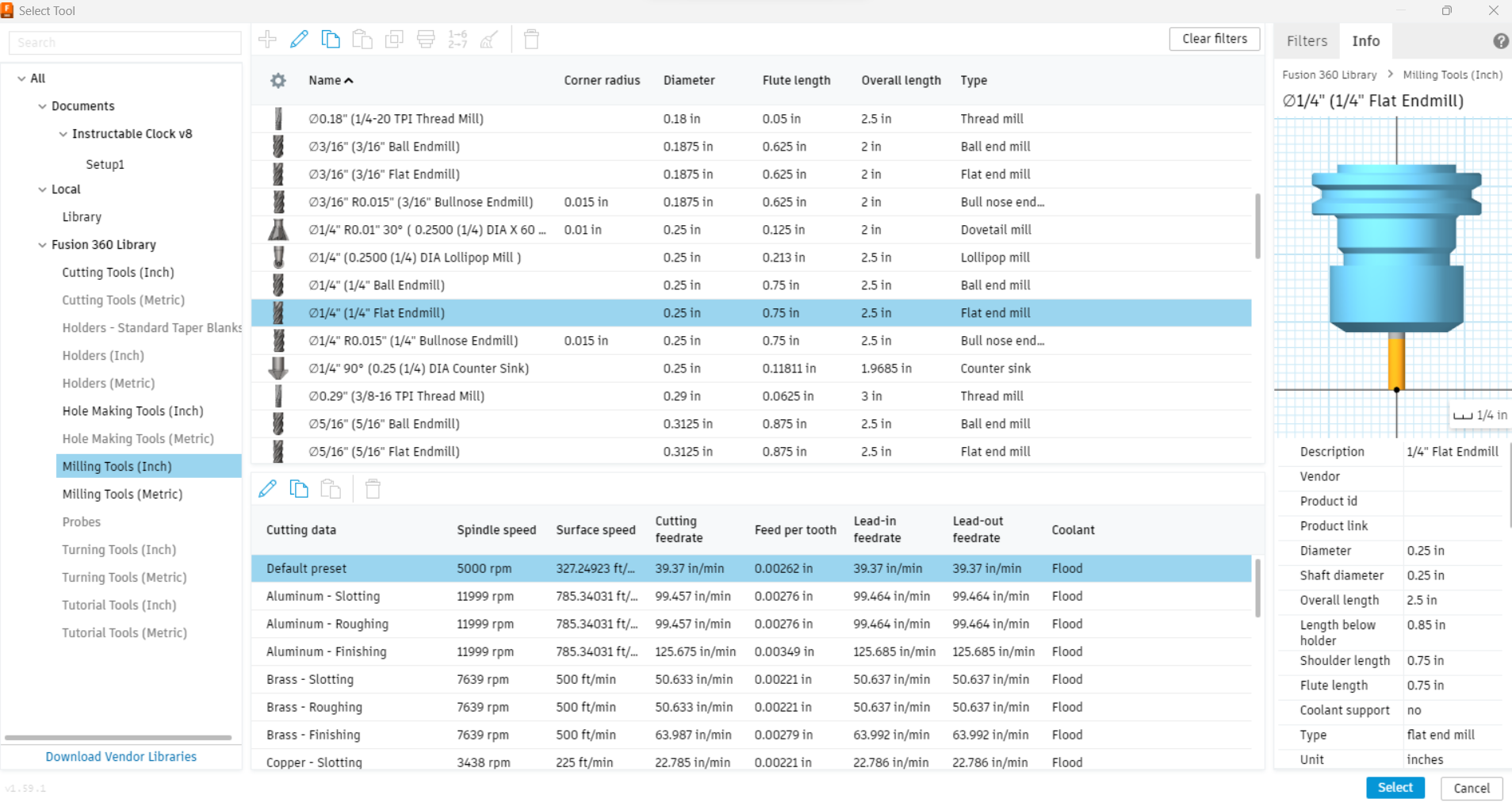
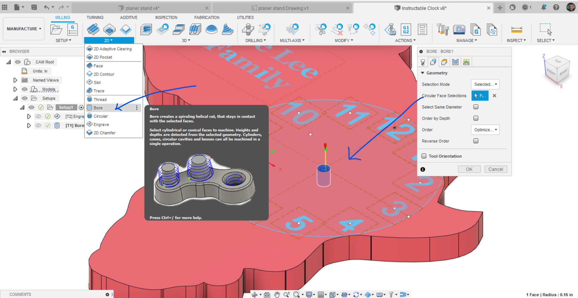
- Select BORE from the 2D menu. Select a 1/4" flat endmill for the tool. Select the hole to bore.
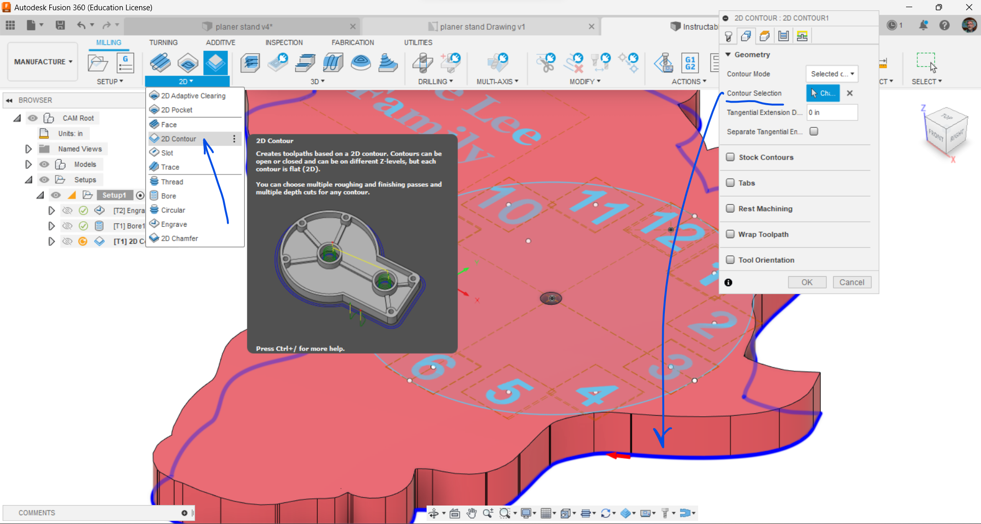
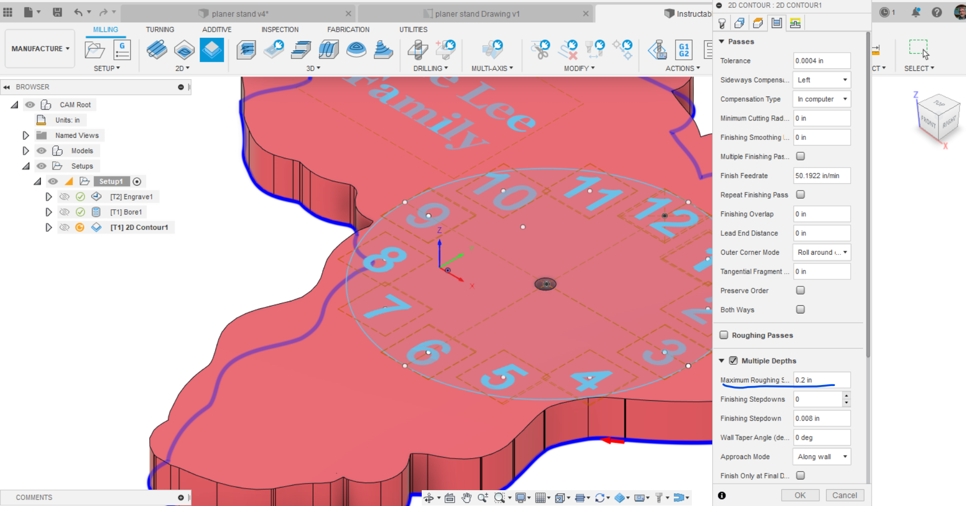
- Select CONTOUR from the 2D menu. The 1/4" bit should be still active from the previous operation. Select the bottom edge of the clock. Select multiple depths with each cut about 1/4" deep to reduce heat and pressure on the bit.
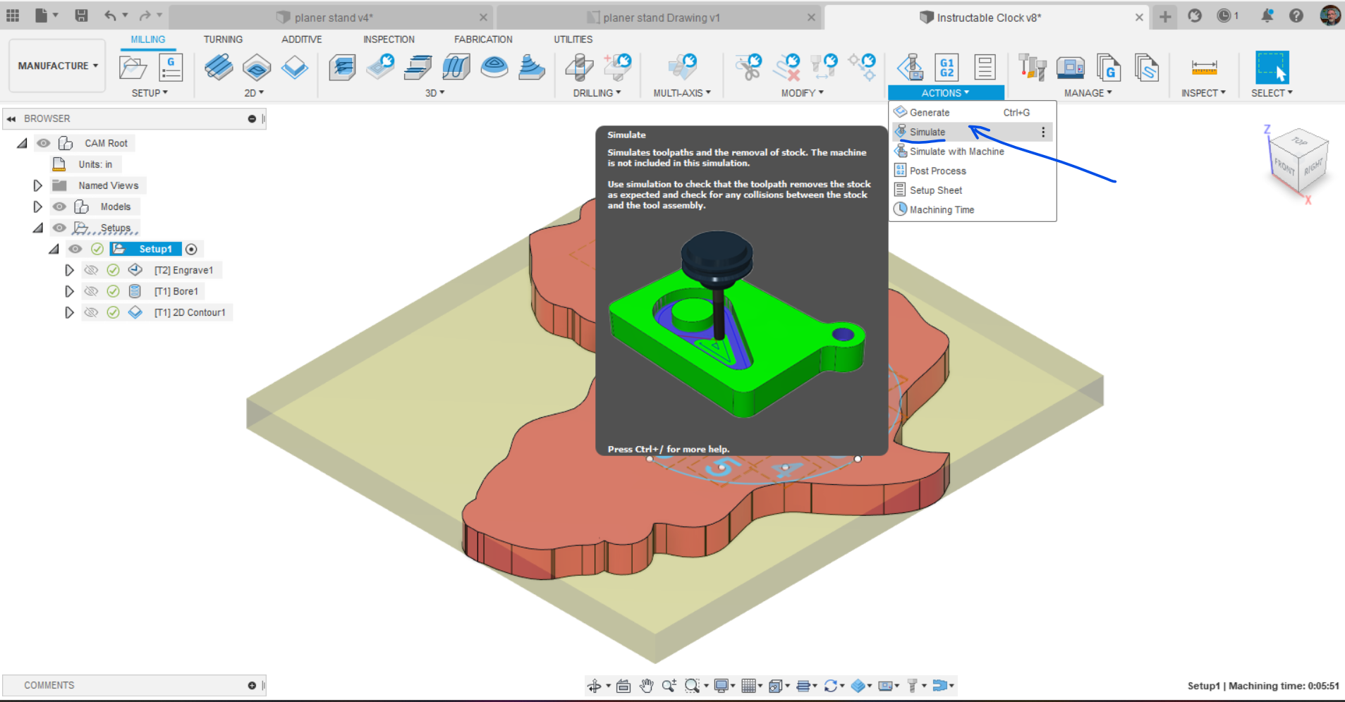
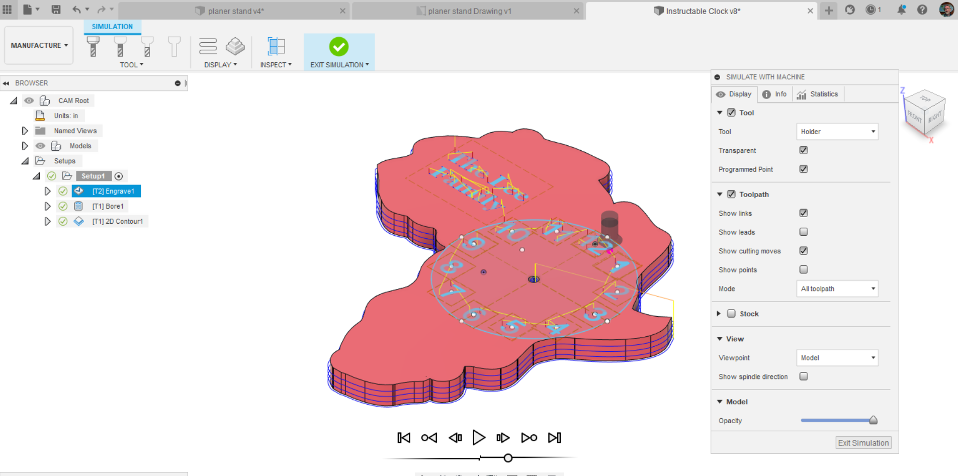
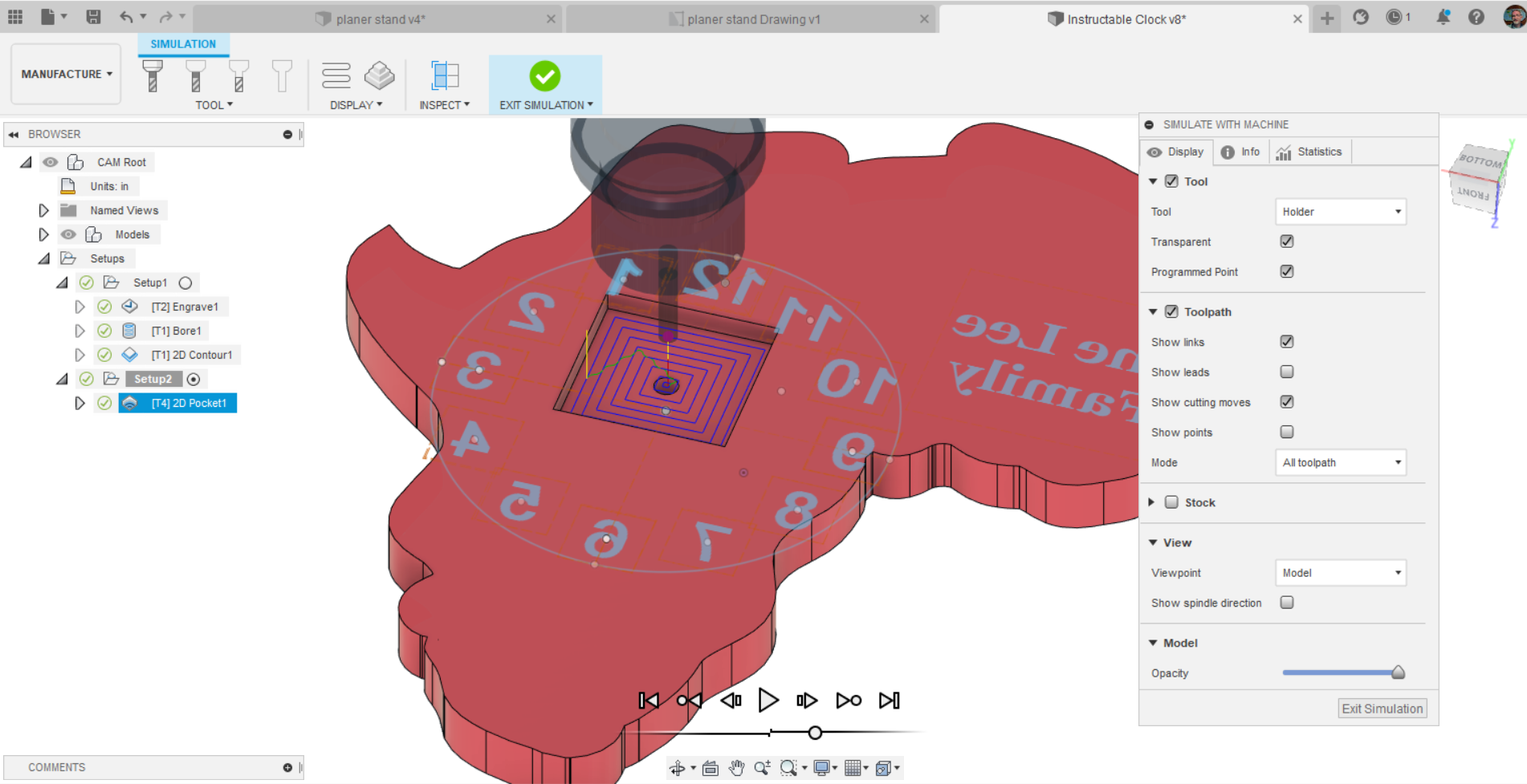
- Simulate all of your operations to make sure that it is cutting what you want. Look from the side to see if the depth looks right for the engraving. If you have put your sketch on the bottom of the clock you will see the bit going all of the way through the clock and engraving on the bottom for example.
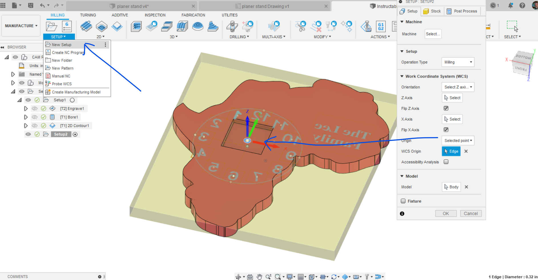
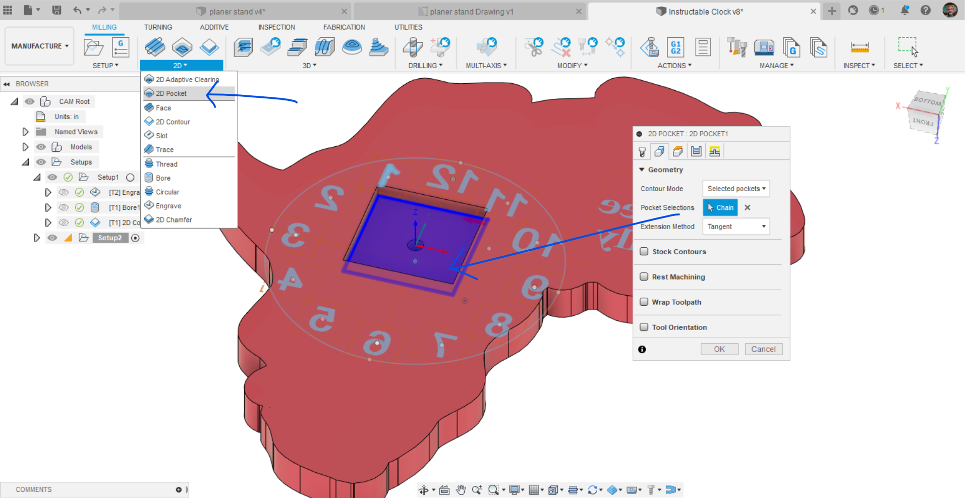
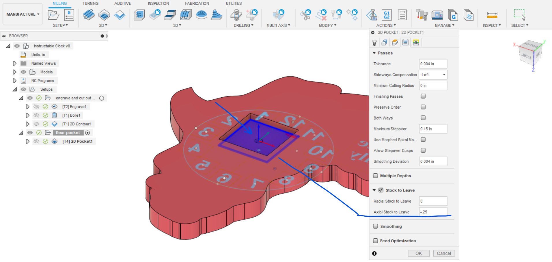
- Orient your clock to see the bottom. Start a new setup so that you can reorient you origin to cut out the inset for the clock movement. Selecting the end of the Z arrow will reverse its direction so that it is pointing upwards if needed. Choose selected point and use the hole as the point of origin. This will be a bit tricky as it wants to make the point at the bottom of the pocket so be aware of this when you home the Z axis. One option would be to select -.25 in the Stock to leave menu. You could also choose a point on the rear surface of the clock like the side of the box or the corner and mark that point on your board to use as home.
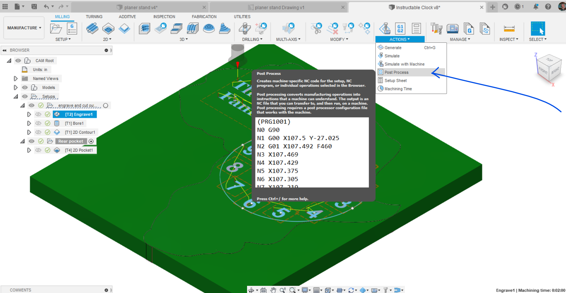
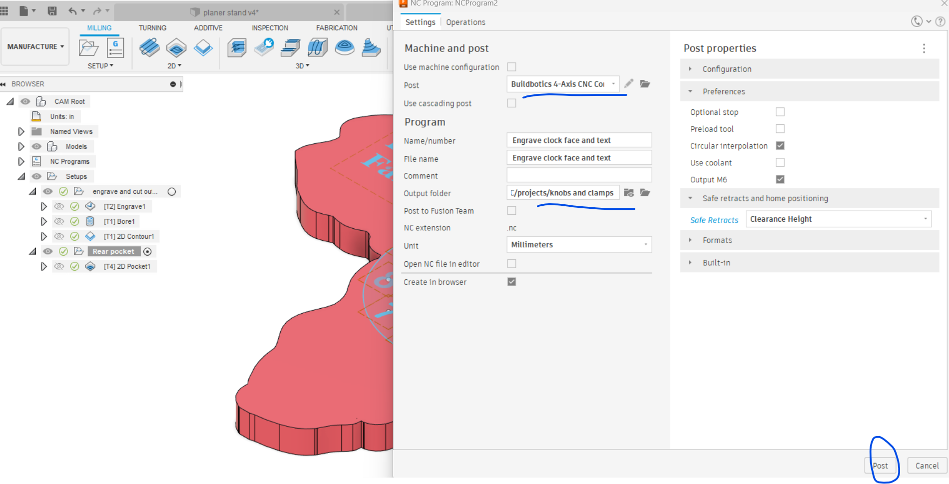
- Post process the operations. You could make a setup for the boring and contour separately from the engrave on the front of the clock and post the setup with both operations as they use the same endmill. Use the .nc output files for the CNC operation.
Paint Your Engraving
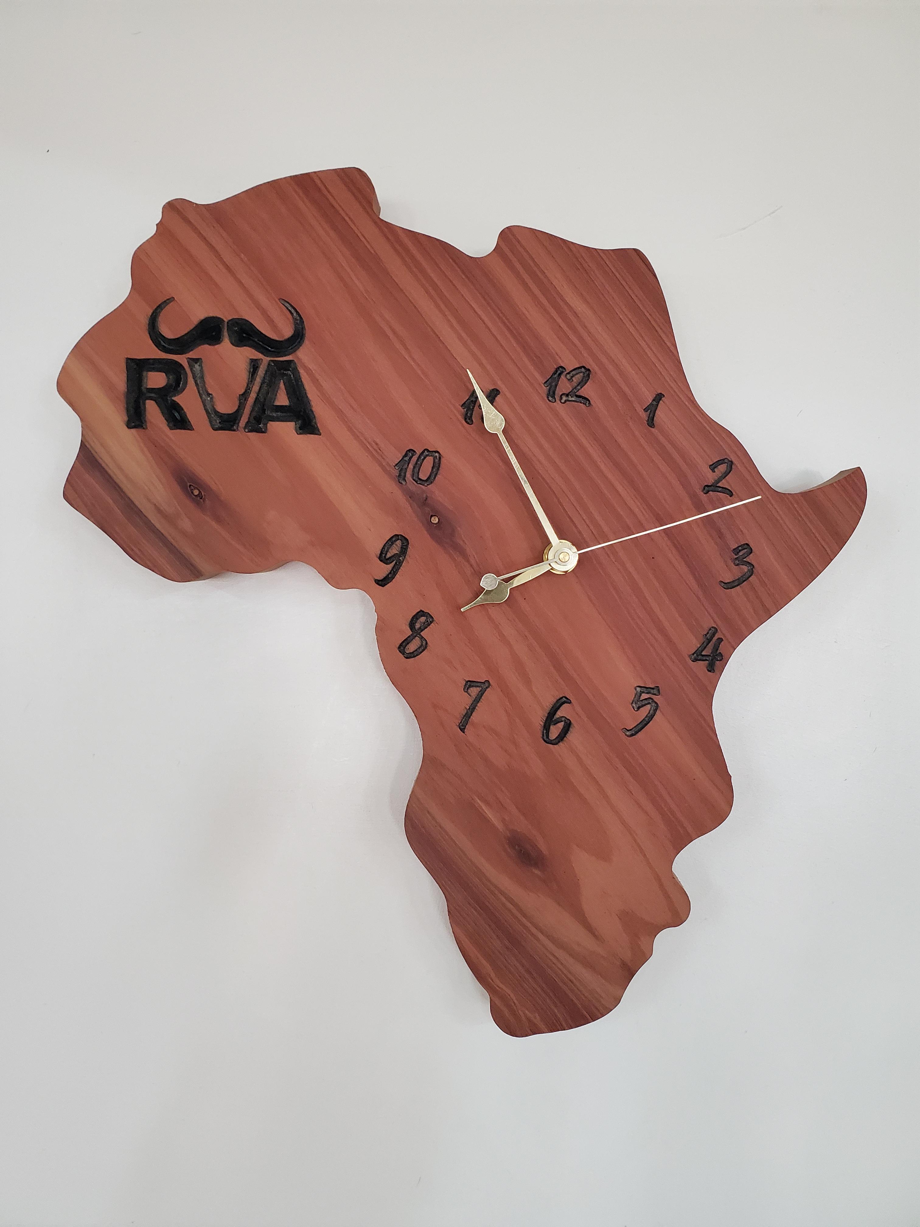
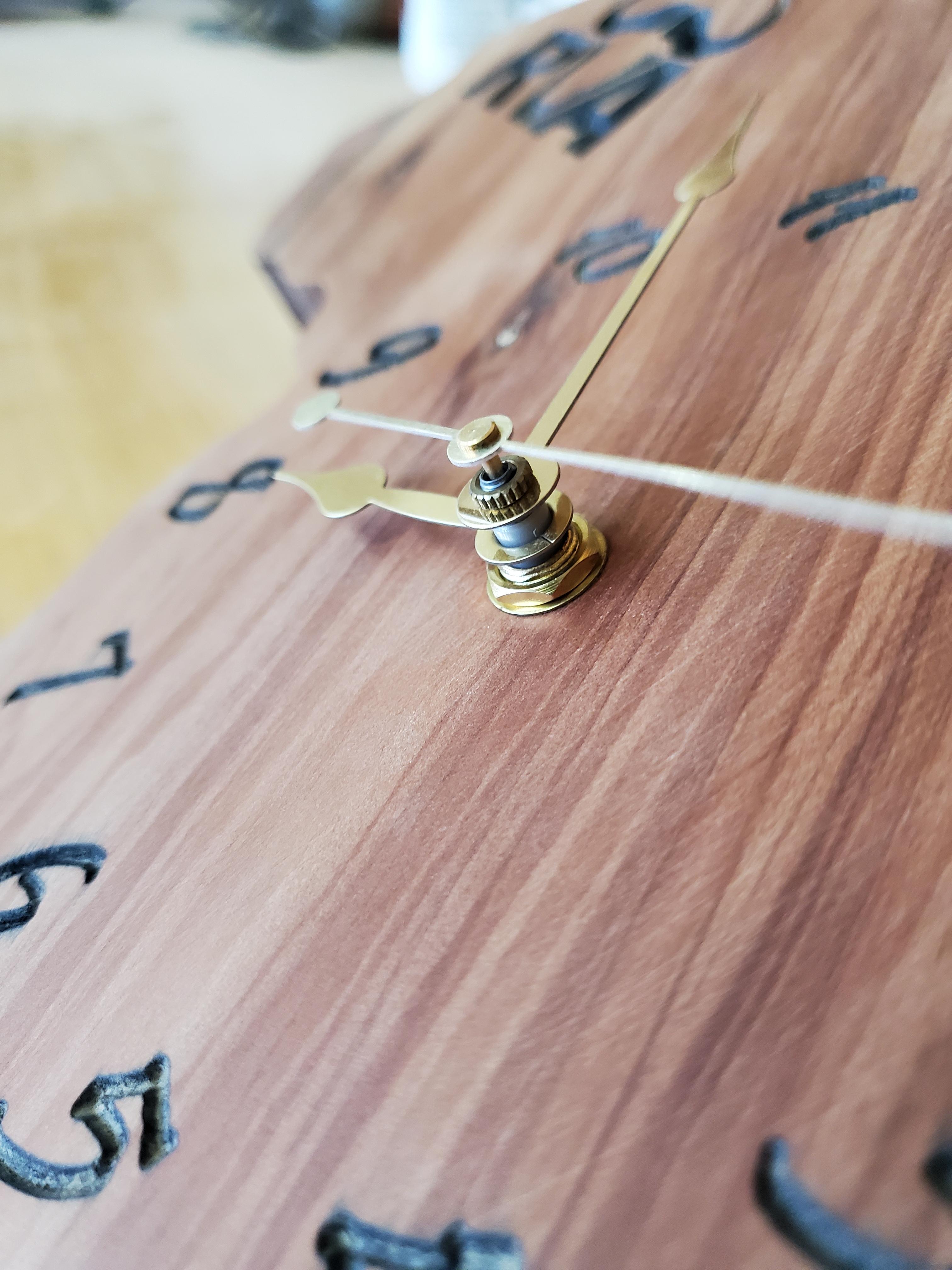
Tape off as much of your clock as practical and paint the engraved parts with spray paint. After the paint dries sand off the face of the clock to remove the paint outside of the engraving. Watch that you don't sand too much if your letters are not engraved deeply as you could sand them off. Varnish your project. Install the clock movement and put the hands on the clock.
Hanging Your Clock
You will need to find where your clock balances properly and drill a hole in the back to hang your clock on the wall.
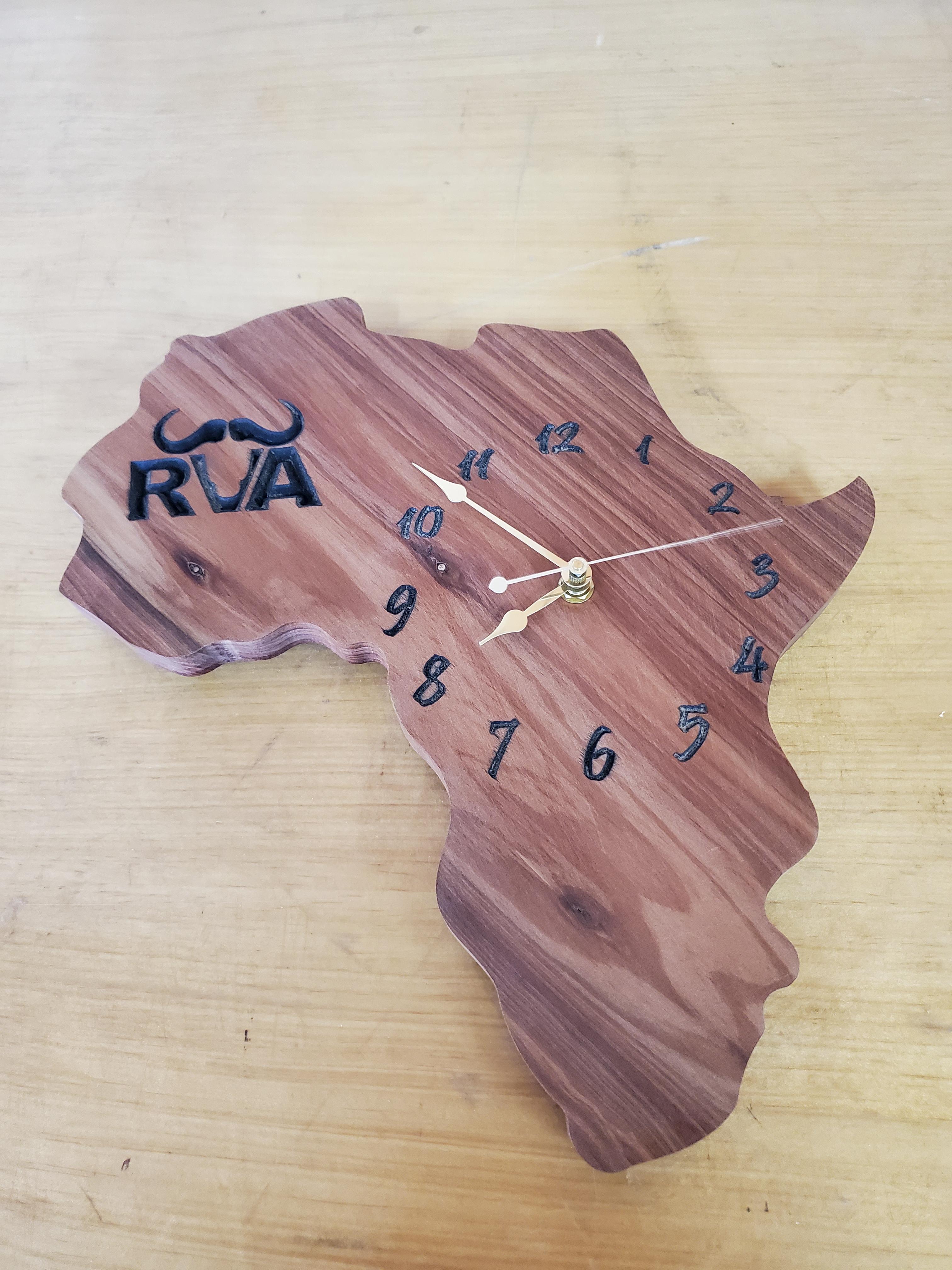
Enjoy Your Clock
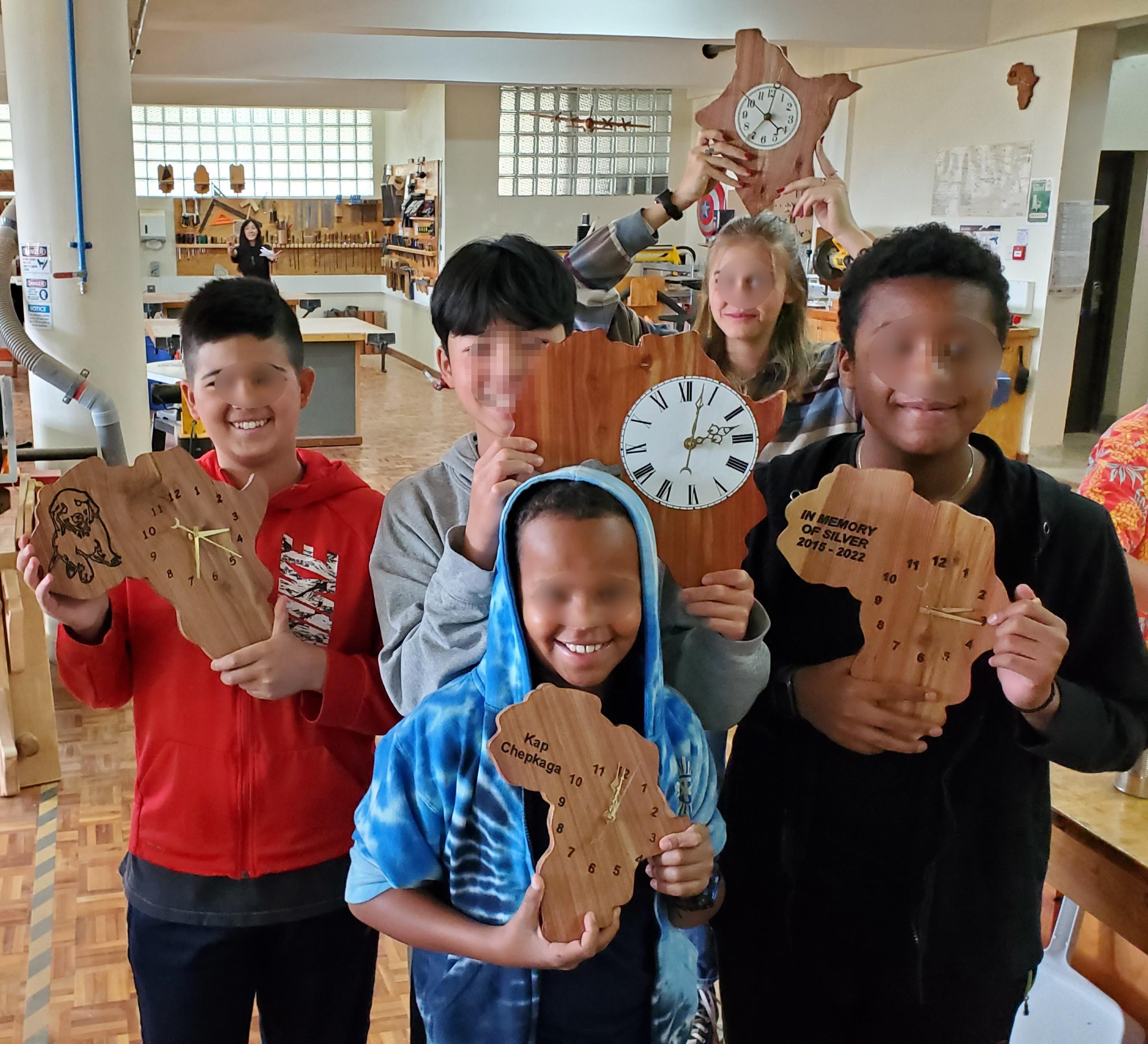
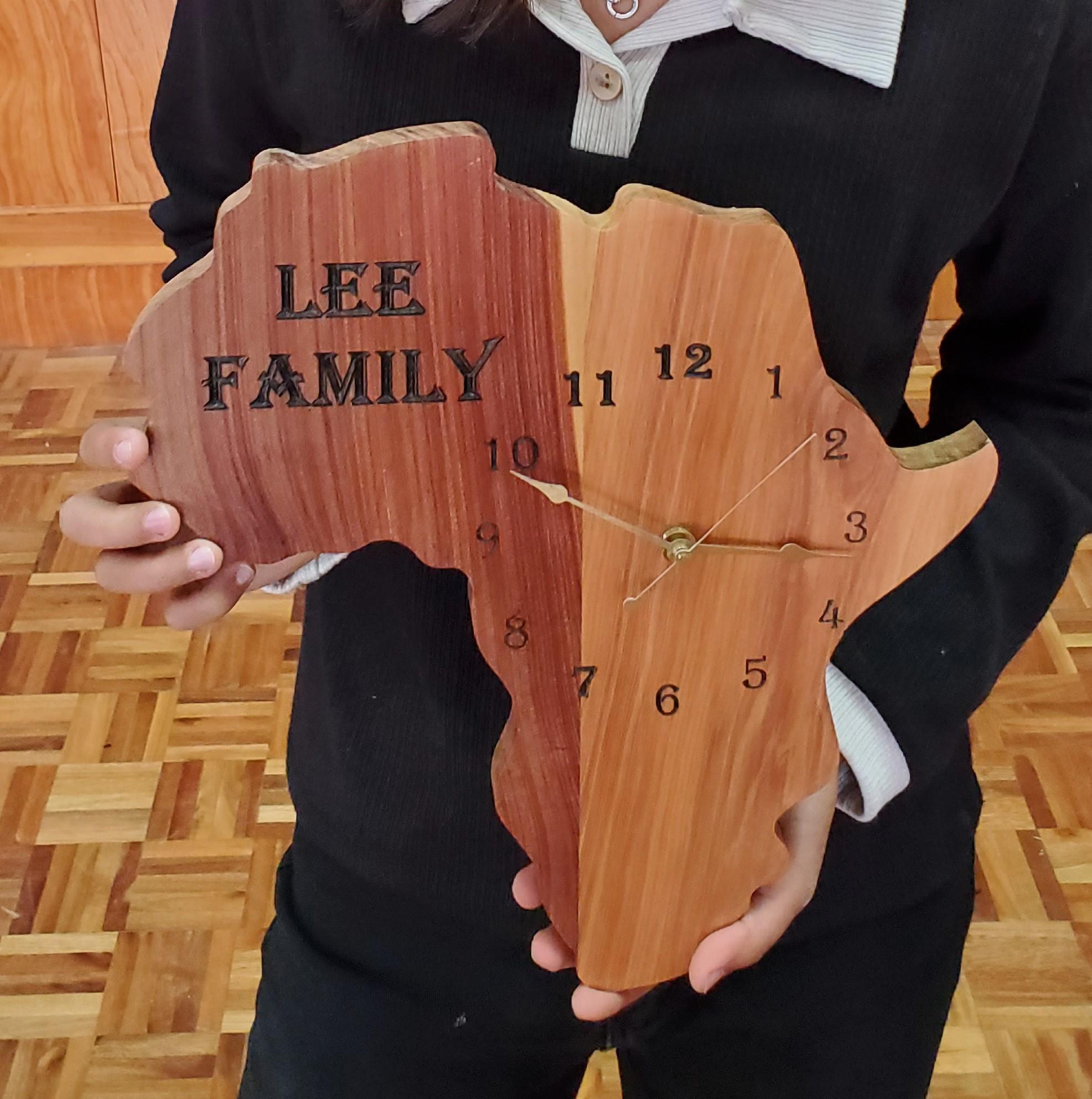
Most people look at a clock several times each day. Who wants a clock you can buy in the store when you can make something amazing like these?