Make a 3D Printed Jack O' Lantern
by crashbot in Workshop > 3D Printing
1802 Views, 21 Favorites, 0 Comments
Make a 3D Printed Jack O' Lantern
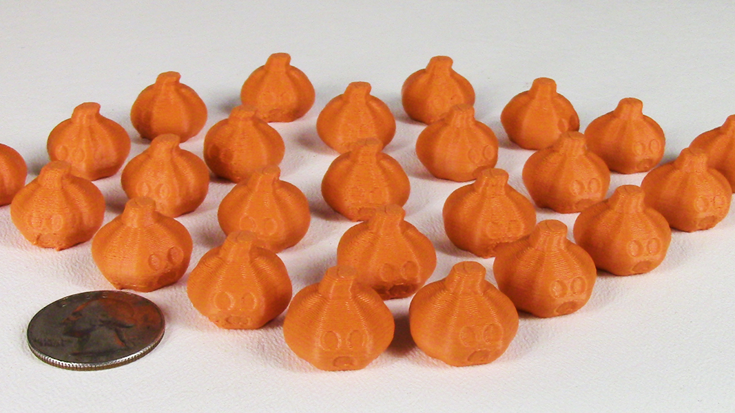
With Halloween just around the corner I wanted to make an Instructable on modeling a 3D printable Jack O' Lantern in the 3D modeling/animation program Blender. Blender is open source and available free at http://www.blender.org.
I've printed quite a few of these recently and they're a big hit, but they might be confused with Halloween candy so keep away from very small children.
I made this Instructable fairly detailed so even a Blender Novice should be able to follow. If you have any questions, please don't hesitate to ask.
For a step-by-step video of the build process go to http://www.teachme3dprinting.com/jack-o-lantern/
Scene Setup
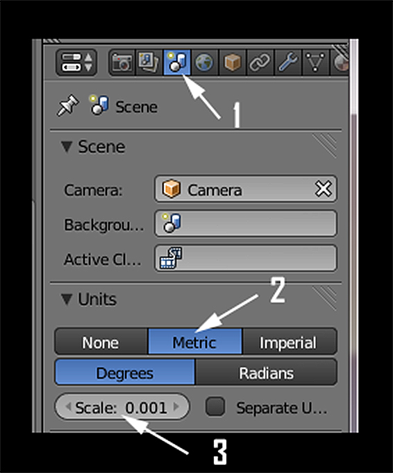
Start Blender and near the upper right corner, click on the Scene icon (1). Blender defaults to a unit of measure called 'Blender Units'. For this tutorial, change the Units to Metric (2). We will be measuring in millimeters so set the Scale to .001 (3).
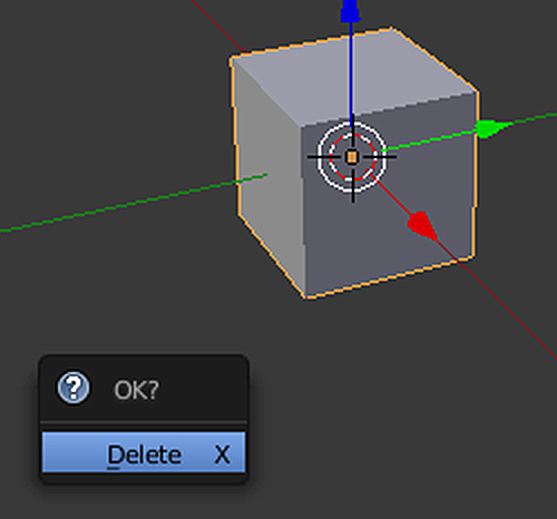
Blenders default scene contains a cube. It should already be selected. You can tell if it's selected by the thin orange outline around it. If it's not, Rt click on the cube to select it. Press the Delete and click on 'Delete' in the dialog that pops up. The cube should now be gone.
Add a UV Sphere
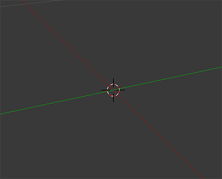
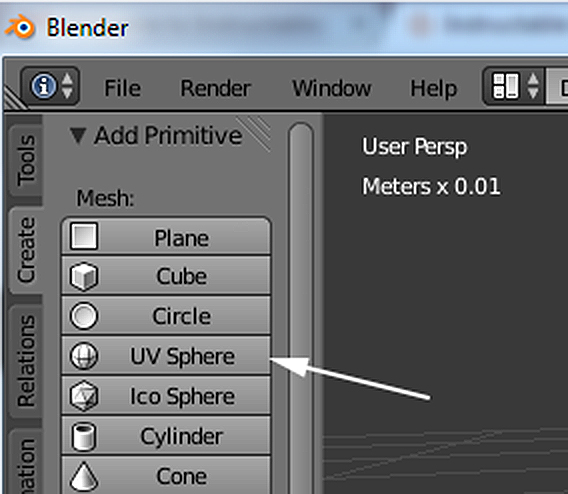
In the center of the 3D View you should see a small red and white striped circle. This is the 3D Cursor. Make sure it's still in the center (If not press 'Shift S' and choose Cursor to Center from the dialog). It's important it's centered because that's where new objects will be created.
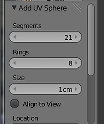
On the left under the Create tab, choose 'UV Sphere'. Below that near the bottom, you'll see the settings for your sphere. We'll change the Segments to 21, the Rings to 8 and the Size to 1cm.
Edge Selection

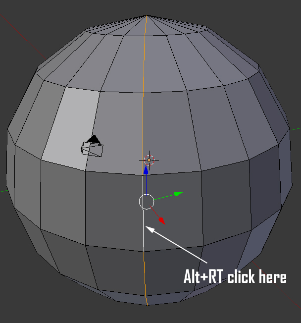
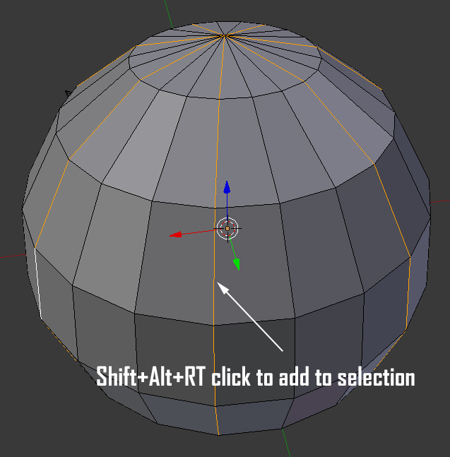
Your sphere should already be selected. We now want to tweak the component parts of the sphere so press 'Tab' to enter Edit mode. We'll want to select the sphere's edges, so near the bottom of the 3D window choose 'Edge Select' mode.
We want to select a ring of edges from top to bottom, so while holding down 'Alt' rt click on an edge where shown. You'll need to add to the selection you just made so go to the left 3 edges and this time select the edge while holding 'Shift' and 'Alt' while Rt clicking. Continue around the sphere selecting every 3rd string of edges with 'Shift' and 'Alt' while Rt clicking. (Hold down middle mouse button to rotate around the scene)
Shape the Pumpkin
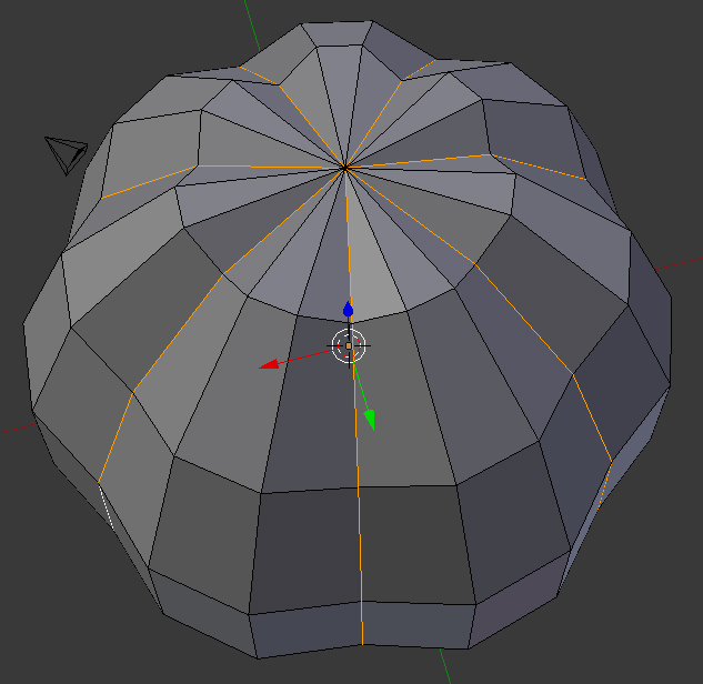
With the edges selected you'll next scale them to form the pumpkin ribs. Type s.93 to scale the edges to .93%. Now that they're scaled, deselect them by pressing 'a'. Now would be a good time to save your work. Save often in case something goes wrong. You can always load a previous save and continue without starting from scratch.
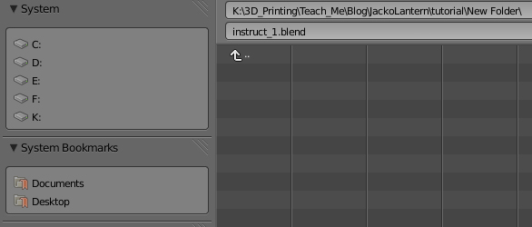
Go to File/Save As. Navigate where you want to save the object and name it and click on 'Save As Blender File'. It will be saved as a '.blend' file. You can can different versions with same base name by pressing the '+' to the right of the name dialog to auto increment the file.
Stem Selection
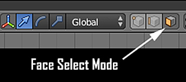
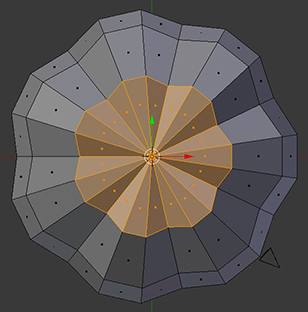
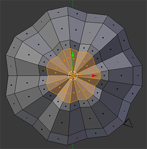
To create a stem let's go to a top view by pressing 7 on your numberpad. Choose 'Face Select' at the bottom. The faces are the flat parts or facets that make up your object. Press 'c' to do a circle selection and click on the top center to select the top faces. Press 'Enter' to drop the circle select tool. You should see the top faces shaded orange to show they're selected.
Inset these a bit by pressing typing 'i .9' ('i' for inset and 0.9 for the amount). Press 'a' to deselect the newly created faces and press 'c' and select the center faces once again. Rt click to drop the selection tool.
Extrude the Stem
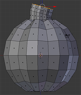
Press keypad 1 for a front view. Look in the upper left corner of the 3D view and make sure it says 'Front Ortho'. If not press keypad 5 to toggle between Perspective and Orthographic views. With the top faces still selected, press 's' then 'z' then '0' and finally 'Enter'. (S is for scale, Z is the axis we want to scale on and 0 is the amount) This will flatten out the top faces. Press 'e' for extrude and extent these faces up a bit. Press LT mouse to set the length. Press 'r' for rotate and rotate the faces as shown. Lt mouse sets the rotation in place. Press 'e' to extrude a bit more.
Save your work again.
Subdivide
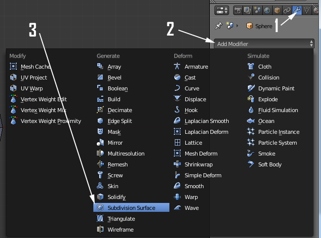
We want to soften out the sharp edges of the pumpkin to give it a more organic shape. We do this with a Subdivision Surface Modifier. On the right properties panel, click on the wrench icon (1). Click on 'Add Modifier' (2) and choose Subdivision Surface (3).
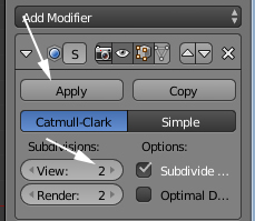
Change the 'Subdivision View' to 2. You're still in edit mode. Press 'Tab' to enter 'Object' mode and press 'Apply' ( you can only apply modifiers in object mode).
Scale and Bisect

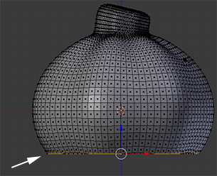
We'll want to scale the pumpkin so type s z .85 and press 'Enter'. This will scale in the Z axis a value of .85 to squash the pumpkin down a bit. Press 'Tab' for 'Edit' mode and choose 'Face Select'.
'A' is your Select/Deselect toggle. Press 'a' to deselect anything that might be selected and then press it again to select everything. We'll want a flat bottom so the jack o' lantern will sit flat on the print bed. You'll use Bisect to slice off the bottom.
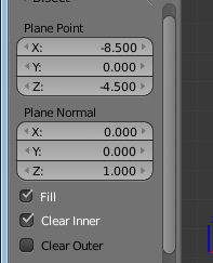
From the left hand Tool Shelf, select the 'Tools' tab and choose 'Bisect'. Place the cursor where indicated, LT click and nudge the mouse to the right. You should see an orange line extend across the pumpkin. You'll now see settings on the left for 'Plane Point' and 'Plane Normal'. For 'Plane Point' type -4.5 for the Z axis. This determines at what height the bisect occurs. To make sure the line is parallel to the ground, enter '0' for both X and Y under 'Plane Normal'. Check 'Fill' to cap off the bottom and 'Clear Inner' to delete the faces below the cut line.
Make an Eye

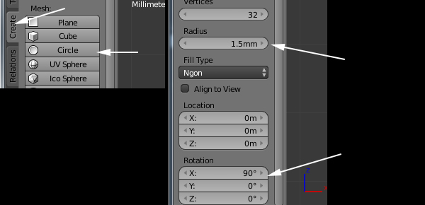
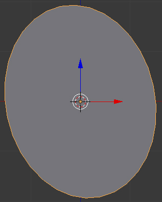
Press 'Tab' to get back into Object mode. We'll create the eyes now so let's go to another layer. Click on layer 2 as indicated. Insure the 3D cursor is still in the center (Shift+S and choose 'Cursor to Center' if it's not). Create a circle with a radius of 1.5mm, ngon fill and rotate it 90 degrees on the X axis. Type sz 1.3 to scale the eye 1.3 times on the Z axis. Press 'Enter' to confirm. Type ry -12 'Enter' to rotate the eye -12 degrees on the Y axis.
Duplicate and Extrude
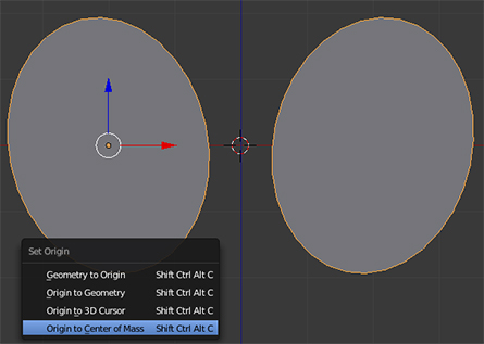
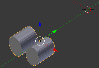
Right now the eye is centered in the 3D space. Move it to the left by typing gx -2mm. Press 'Enter'. (g for Grab or move, X the axis we move it on and -2mm is the amount of movement) Press 'Shift +'d' to duplicate the eye. This automatically puts you in move mode so type x 4 to move 4mm on the X axis. Press 'Enter'. Rotate the new eye in the opposite direction by typing ry 24. Press 'Enter'.
The eye on the right should be selected. Add to this selection by 'Shift+RT clicking' on the left eye. With both eyes selected, press 'Ctrl + j' to join them as one object. We want the object manipulator in the center so press and hold 'Shift+Ctrl+Alt+c' and choose 'Origin to Center of Mass' from the dialog that pops up.
Before we go further, we want to set the scale and rotation. Make sure the Object Properties Panel on the right is open (if not you can toggle it on by pressing 'n'). You see the values we have for scale and rotation. Press 'Ctrl+a' for Apply and choose 'Rotation and Scale' from the dialog. Notice the rotation is now at '0' and scale is set to '1'.
Hold down the middle mouse wheel and rotate the view so you can see more from the side of the eyes. We'll give it some thickness. Press 'Tab' for edit mode (you should still be in Face Select) and press e4 to Extrude the eyes 4mm. Tab back into object mode. Move the eyes along the Y axis 12mm by typing gy -12 'Enter'.
Save your work.
Position the Eyes

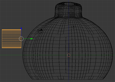
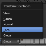
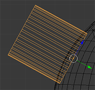
You'll now use these eye shapes to drill into the pumpkin. Press 'm' and click on layer 1 to move the eyes to the pumpkin layer. Select layer 1 to see both objects. We need to rotate the pumpkin a bit so press 7 for a top view. Rt click on the pumpkin to select it. Press 'z' for a wireframe view and type 'rz -12.8 Enter' to rotate on the Z axis -12.8 degrees. Now the flat part of the pumpkin is facing the eyes. Select the eyes and press keypad '3' for a side view. Move the eyes into position as shown. Rotate the eyes on the x axis (rx) til they're roughly parallel with the pumpkin surface. At the bottom of the 3D viewer window, change to local orientation and move the eyes until they intersect the pumpkin surface.
Boolean the Eyes
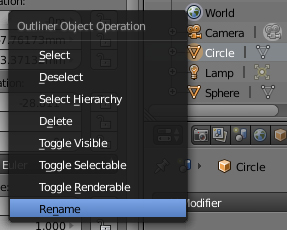

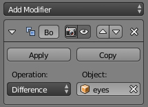
Let's name the eyes properly. Go to the Outliner Panel at the top righthand side and Rt click on 'Circle'. Choose Rename at the bottom and type 'eyes' (press Enter when done). We want to use the eyes as a drill to cut their shape into the pumpkin. Select the pumpkin and go to the Tools panel and add a Boolean Modifier.
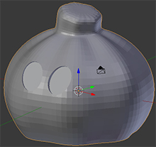
In the settings choose 'Difference' as the Operation and 'eye' as the Object to use as a drill. Press 'Apply'. Select the eyes object and delete. Press 'z' to see your pumpkin as solid shaded, and use the middle mouse to rotate around the view and admire your work.
Save your work.
Make the Mouth

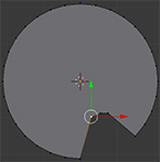
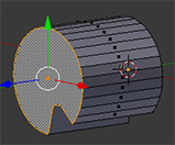
Go to layer 2. Ensure your 3D cursor is in the center and create another Circle. Give it a radius of 2.1mm, an ngon fill and a Rotation of 90 degrees on the x. Press 1 for a front view and 'Tab' for Edit mode. Click on Vertex select as shown.
We'll make a tooth shape for the bottom of the mouth. Count 3 vertices (points) over from the bottom and Rt click and hold as you move the vertex up. Lt click to set it in place Do the same for the next two vertices as shown. Go to Face select mode and Rt click to select the mouth. type 'e4' and Enter to extrude the mouth shape 4mm. Rotate around with the middle mouse button to check. Tab to get to Object mode and 'Ctrl+a' for 'Apply'. Choose 'Rotation' to set the current rotation as default.
Move the mouth -10mm on the Y axis by typing 'gy -10mm'. Press 'Enter'. Move to layer 1.
Position and Boolean the Mouth
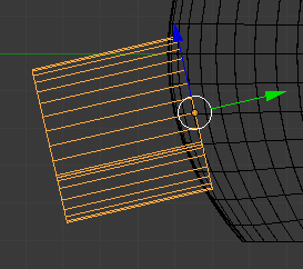
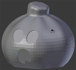
You should still be in Local Orientation. Move and rotate on the X to position the mouth as shown. Rt click on 'Circle' in the Outliner and rename to 'mouth'. Select the pumpkin and add a Boolean Modifier like you did with the eyes. Set the Operation the 'Difference' and the Object to 'mouth'. Press Apply. Delete the mouth object. Press 'z' to solid shade the pumpkin and rotate your view to check it out.
Position Jack O' Lantern and Export
Almost Done...
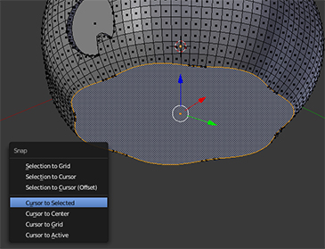
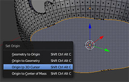
We'll want the pumpkin to be sitting flat on the print bed. Make sure the pumpkin is still selected. Tab into Edit Mode and click Face Select. Rotate your view and select the large face at the bottom. Snap the 3D Cursor to this selection by pressing 'Shift+s' and selecting 'Cursor to Selected'. Tab into Object mode and press and hold 'Shift+Ctrl+Alt and C. Choose 'Origin to 3D Cursor'. Snap the origin to the ground plane with 'Atl+g'. Export as an .stl file by going to File/Export and choosing Stl (.stl). Navigate to a location, name it and press 'Export STL'.
Save one last time.
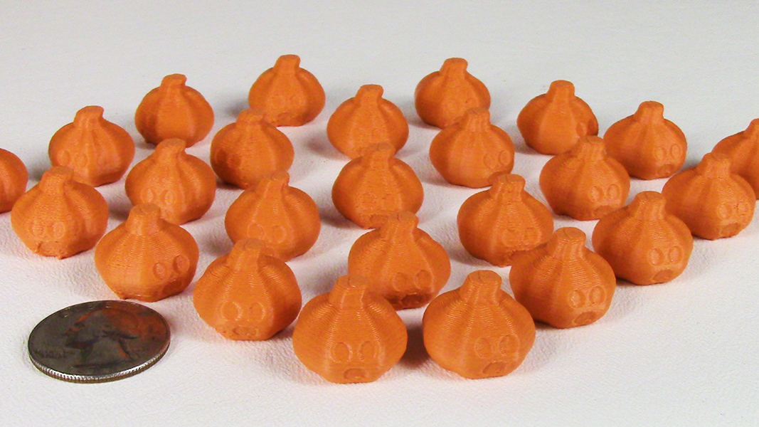
Because of the small detail I printed several at a time. This gives the layers a chance to cool and firm up before the printer deposits another layer on top.
Enjoy!