Make Your Own ESP32 Simple
by No_Need_Loi in Circuits > Arduino
8466 Views, 26 Favorites, 0 Comments
Make Your Own ESP32 Simple

.png)
A feature-rich MCU with integrated Wi-Fi and Bluetooth connectivity for a wide-range of applications
ESP32 is capable of functioning reliably in industrial environments, with an operating temperature ranging from –40°C to +125°C. Powered by advanced calibration circuitries, ESP32 can dynamically remove external circuit imperfections and adapt to changes in external conditions.
Engineered for mobile devices, wearable electronics and IoT applications, ESP32 achieves ultra-low power consumption with a combination of several types of proprietary software. ESP32 also includes state-of-the-art features, such as fine-grained clock gating, various power modes and dynamic power scaling.
ESP32 is highly-integrated with in-built antenna switches, RF balun, power amplifier, low-noise receive amplifier, filters, and power management modules. ESP32 adds priceless functionality and versatility to your applications with minimal Printed Circuit Board (PCB) requirements.
ESP32 can perform as a complete standalone system or as a slave device to a host MCU, reducing communication stack overhead on the main application processor. ESP32 can interface with other systems to provide Wi-Fi and Bluetooth functionality through its SPI / SDIO or I2C / UART interfaces.
Supplies
.png)
.png)
.png)
.png)
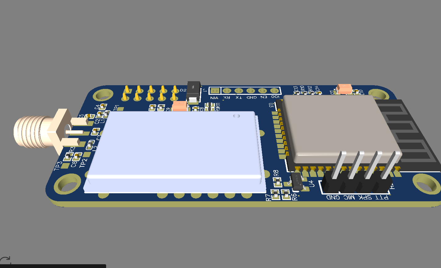
ESP32 became one of the most common MCU due to its versatile functions. In the past years, this MCU fell in the taste of the IoT developers and hobbyists. ESP32 integrates a rich set of peripherals, ranging from capacitive touch sensors, Hall sensors, SD card interface, Ethernet, high-speed SPI, UART, I²S, and I²C. This MCU is commonly found in his module version ESP32-WROOM. The figure below shows the sketch of the ESP-WROOM module.

As you can see, the module has castellated side pins, making it a good choice for hobbits. Because of that, in this tutorial, we will learn how to make a breakout board for your ESP32-WROOM, with its minimal needed circuitry. It is also good to note that this circuit is the base design for any ESP32 breakout board, so you can reuse it for your future PCBs.
Open Proteus software and go to the Pick Device window. You can open this window by clicking the icon on your left (red arrow). Once it opens, type in the Keyword tab “ESP32”. As I already have it in my library, it appears solo.

If you don’t have it in your library, you can click on the yellow bar on the bottom of the Pick Device window. Once you click the yellow bar, a list of components will appear. All of them are ESP32, they differ by the size of the flash memory and layout. We are using in this tutorial the ESP32-WROOM-32D 4Mb. The figure below shows the selected one.

To add in your schematic, you just need to click ok and double-click the select one.

Now let’s insert the LEDs for indication and power regulator. Repeat Step 1 and place LM1117, TBLOCK-l2, 10uF cap, 47uF cap, 300 ohms res, and a LED (in this tutorial LTST-C191KRKT).

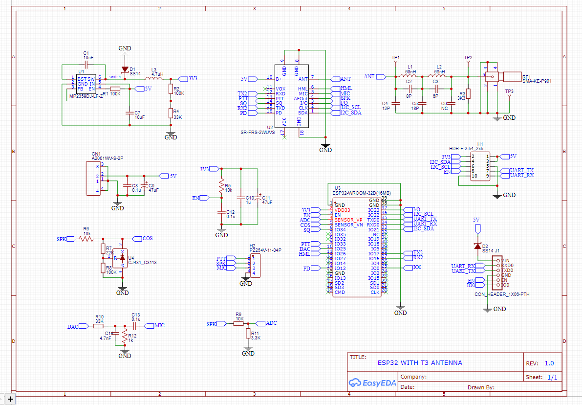
Now build the following circuit shown below.

Step 5
In this step, we will add a BIDIR terminal in all ESP32 pins that were not yet connected. In this tutorial, each module pin has a respective connector. Place a CONN-SIL10, CONN-SIL18, CONN-SIL6 and have a circuit as shown below:


Step 6
Now, that the schematic is complete, click on the icon shown in the figure below.

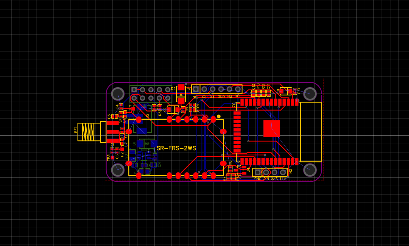
A window will open where you can make the layout of your board. Go to Component Mode and start placing the items that appear on the Component Window. To place the components you just need to select them in the Component Window and click on the layout window.
Now click on Autorouter on the top corner and then click Begin Routing.

By default, it will run a 2-layer connection.
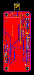
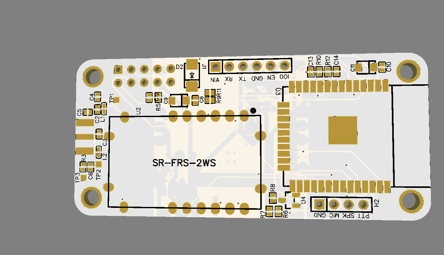
Designing the Board
.png)
.png)
ESP32-wroom needs few connections to work. These connections are VDD, Ground, Enable, and Io0. VDD and Ground are obviously power pins, so we only need to add external components for Enable and Io0. Enable must be set to 3.3v in order to let the chip run, by adding a push-button, we can send Enable to the ground, allowing the reset of the ESP32. Io0 sets the module in program state when LOW, for example, to program ESP32-wroom, you just need to set Io0 to ground and then set Enable pin also to ground. By adding a push button and a pull-up in Io0, you can control when to program your module.
Now, repeat Step-1 and add the push-button PT636 SK25J SMTR, 10K resistors, and a 4-pin connector. After that, rearrange and connect the components. The figure below shows how your circuit should look like
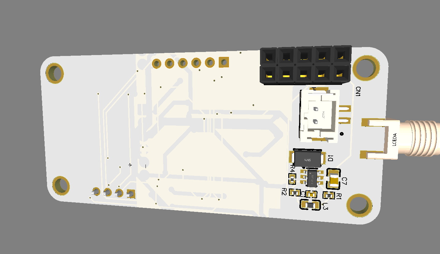
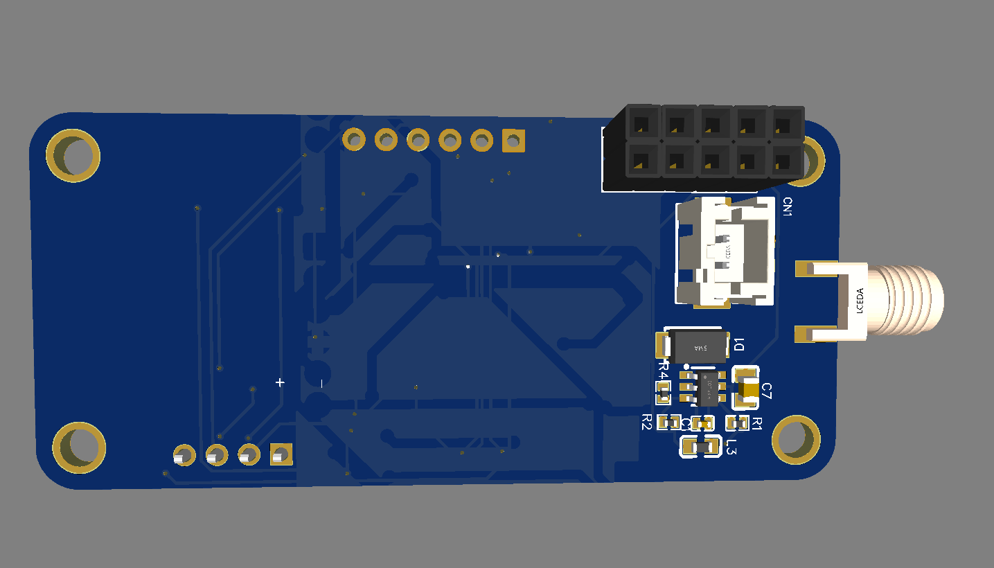
Ordering PCB From JLCPCB
.png)
.png)
.png)
.png)
.png)
This project contains PCB and which was made with the help of JLCPCB
JLCPCB has upgraded the via-in-pad process of all 6-20 layer PCBs for free and provides free ENIG to make PCB products more stable and reliable. It is worth mentioning that due to large-scale production capabilities, JLCPCB is able to reduce the cost, allowing everyone to truly enjoy the benefits of the JLCPCB advanced fabrication. Here at JLCPCB, you can also get 1-8 layer PCBs at only $2
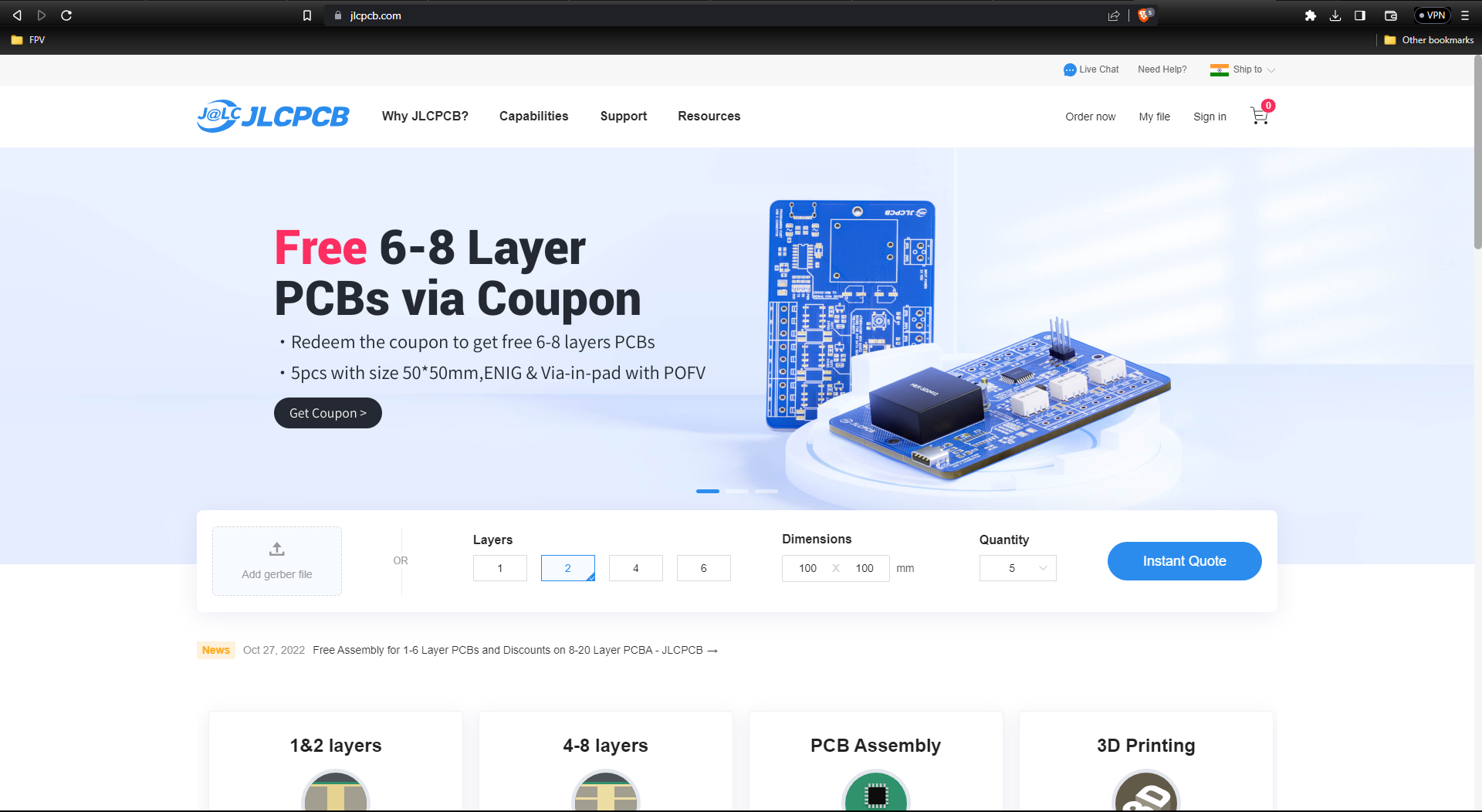
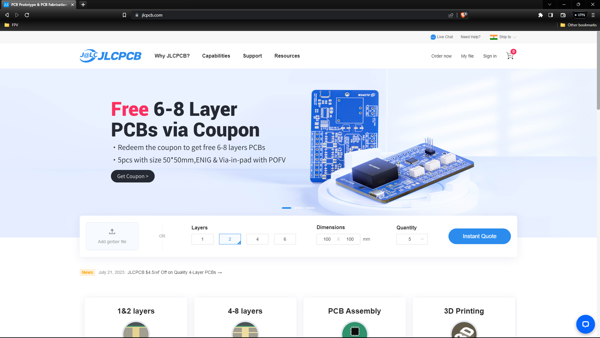
Go to JLCPCB website and create a free account.
Register and Login using Google Account is also possible.
Step 2 – Upload Gerber File
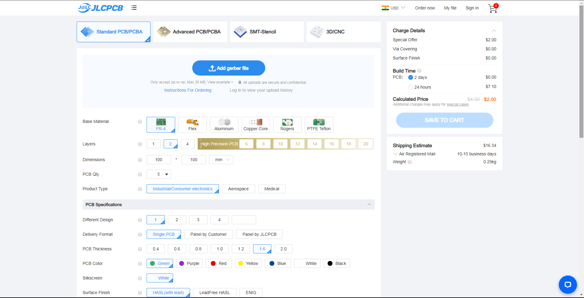
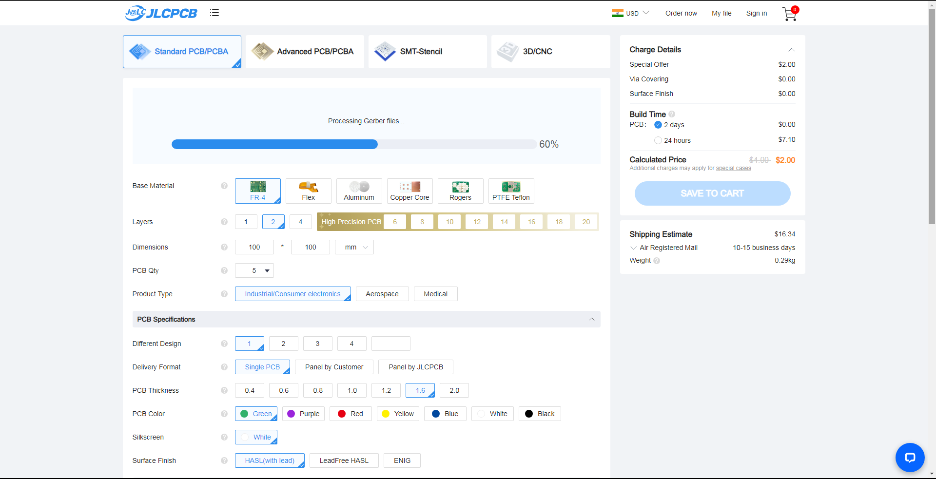
Once you have successfully created an account, Click on “Quote Now” and upload your Gerber File.
Gerber File contains information about your PCB such as PCB layout information, Layer information, spacing information, tracks to name a few.
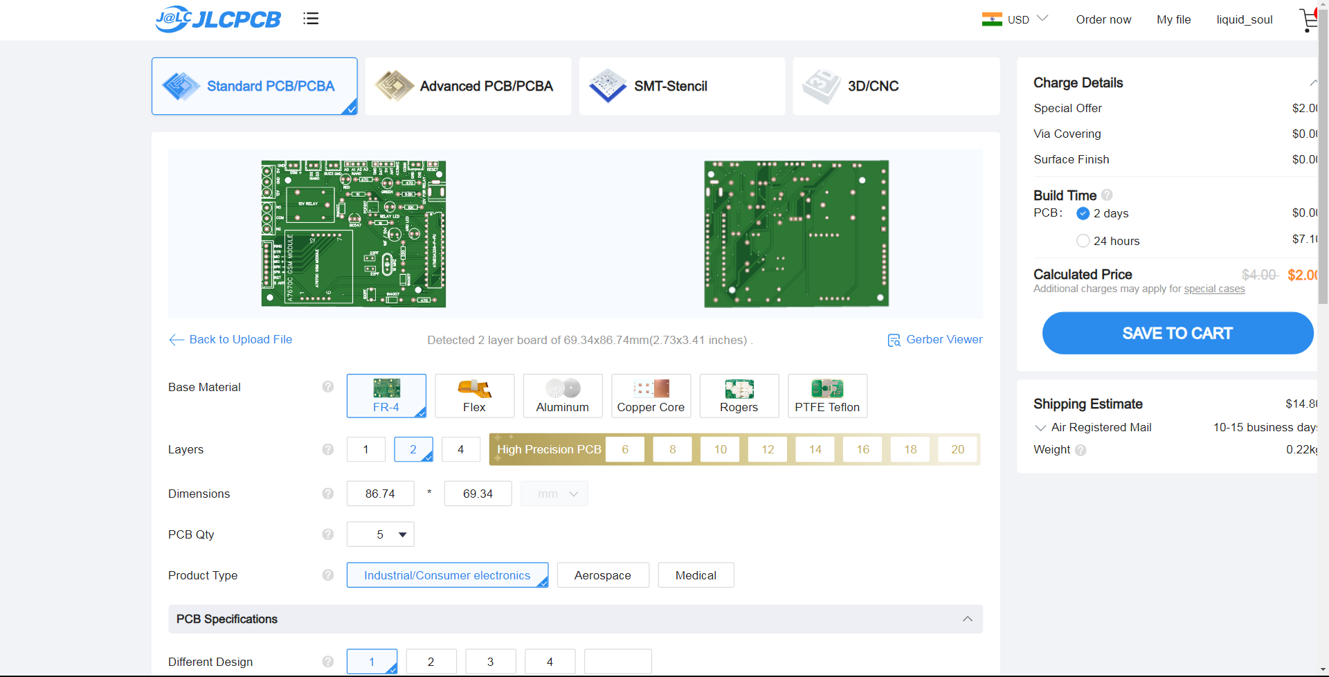
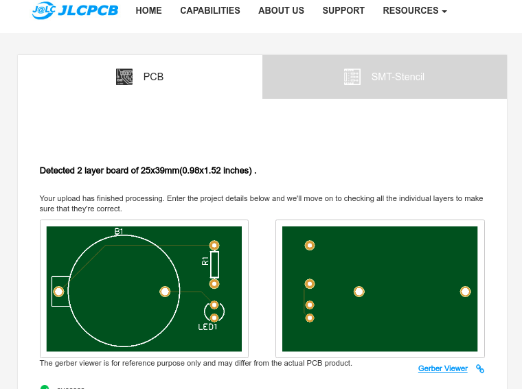
Step 3 – Preview the File
Once the Gerber file is uploaded, it will show you a preview of your circuit board.
Make sure this is the PCB Layout of the board you want.
Step 4 – Choose Necessary PCB Options
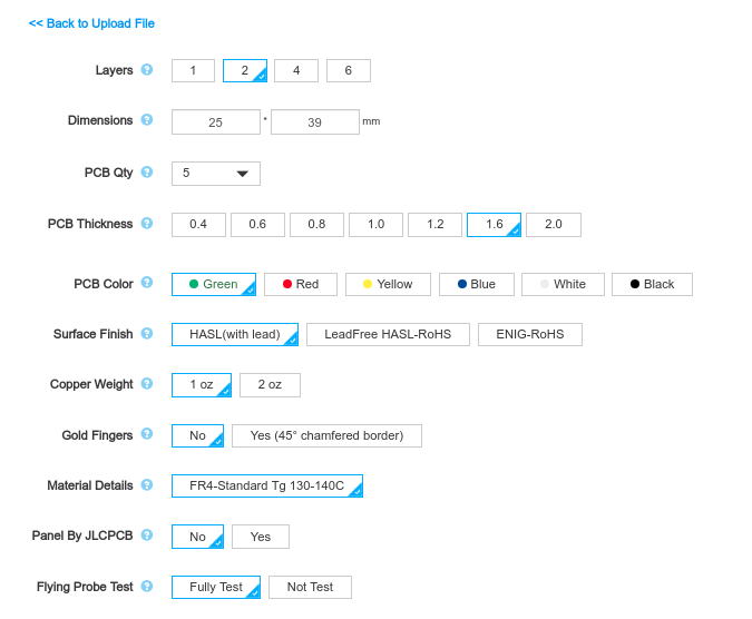
Below the PCB preview, you will see so many options such as PCB Quantity, Texture, Thickness, Color etc. Choose all that are necessary for you.
Programming ESP32 With Arduino IDE
To program your boards, you need an IDE to write your code. For beginners, we recommend using Arduino IDE. While it’s not the best IDE, it works well and is simple and intuitive to use for beginners. After getting familiar with Arduino IDE and you start creating more complex projects, you may find it useful to use VS Code with the Platformio extension instead.
If you’re just getting started with the ESP32, start with Arduino IDE. At the time of writing this tutorial, we recommend using the legacy version (1.8.19) with the ESP32. While version 2 works well with Arduino, there are still some bugs and some features that are not supported yet for the ESP32.
Installing Arduino IDE
To run Arduino IDE, you need JAVA installed on your computer. If you don’t, go to the following website to download and install the latest version: http://java.com/download.
Downloading Arduino IDE
To download the Arduino IDE, visit the following URL:
Don’t install the 2.0 version. At the time of writing this tutorial, we recommend using the legacy version (1.8.19) with the ESP32. While version 2 works well with Arduino, there are still some bugs and some features that are not supported yet for the ESP32.
Scroll down until you find the legacy version section.

Select your operating system and download the software. For Windows, we recommend downloading the “Windows ZIP file“.
Running Arduino IDE
Grab the folder you’ve just downloaded and unzip it. Run the executable file called arduino.exe (highlighted below).

The Arduino IDE window should open.

Installing the ESP32 in Arduino IDE
To be able to program the ESP32 using Arduino IDE, you need to add support for the ESP32 boards. Follow the next steps:
- Go to File > Preferences.

- Enter the following into the “Additional Board Manager URLs” field. This will add support for ESP32 and ESP8266 boards as well.
https://raw.githubusercontent.com/espressif/arduino-esp32/gh-pages/package_esp32_index.json, http://arduino.esp8266.com/stable/package_esp8266com_index.json
See the figure below. Then, click the “OK” button.

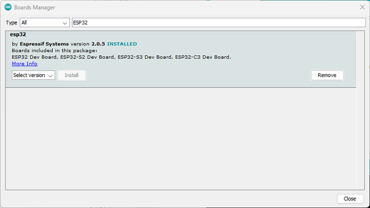
- Open the Boards Manager. Go to Tools > Board >Boards Manager…
- Search for ESP32 and install the “ESP32 by Espressif Systems“:
That’s it. It will be installed after a few seconds.
After this, restart your Arduino IDE.
Troubleshooting
.png)
.png)
.png)
.png)
Upload Code to the ESP32 using Arduino IDE
To show you how to upload code to your ESP32 board, we’ll try a simple example available in the Arduino IDE examples for the ESP32.
First, make sure you have an ESP32 selected in Tools > Board. Then, go to File > Examples > WiFi > WiFiScan.
This will load a sketch that scans Wi-Fi networks within the range of your ESP32 board.

Connect your ESP32 development board to your computer using a USB cable. If you have an ESP32 DEVKIT DOIT board, the built-in red LED will turn on. This indicates the board is receiving power.
Important: you must use a USB cable with data wires. Some USB cables from chargers or power banks are power only and they don’t transfer data—these won’t work.
Now, follow the next steps to upload the code.
1) Go to Tools > Board, scroll down to the ESP32 section and select the name of your ESP32 board. In my case, it’s the DOIT ESP32 DEVKIT V1 board.
2) Go to Tools > Port and select a COM port available. If the COM port is grayed out, this means you don’t have the required USB drivers. Check the section Installing USB Drivers before proceeding.

3) Press the upload button.

Some boards will automatically go into flashing mode and the code will be successfully uploaded straight away.
Other boards don’t go into flashing mode automatically, so you may end up getting the following error.
Failed to connect to ESP32: Timed out... Connecting...
Or something like:
A fatal error occurred: Failed to connect to ESP32: Wrong boot mode detected (0x13)! The chip needs to be in download mode.
This means the ESP32 was not in flashing mode when you tried to upload the code. In this situation, you should long press the board BOOT button, when you start seeing the “Connecting….” message on the debugging window.
Note: in some boards, a simple trick can make the ESP32 go into flashing mode automatically. Check it out on the following tutorial: [SOLVED] Failed to connect to ESP32: Timed out waiting for packet header.
Now, the code should be successfully uploaded to the board. You should get a “Done uploading “message”.
