Make Blynk Switch IoT 4CH Only Use Smartphone (ESP8266 Loader)
by bluino_electronics in Circuits > Arduino
8876 Views, 29 Favorites, 0 Comments
Make Blynk Switch IoT 4CH Only Use Smartphone (ESP8266 Loader)
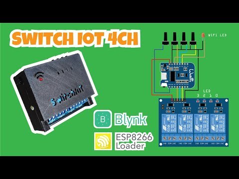
in this tutorial, I will show you simple home automation using app, you can control 4 channel home appliances using the Blynk app and also a physical switch. To build this project only need Smartphone Android with ESP8266 Loader app, you can upload firmware directly from your Android Smartphone to Wemos ESP8266 board use the ESP8266 Loader app.
Part Requirements
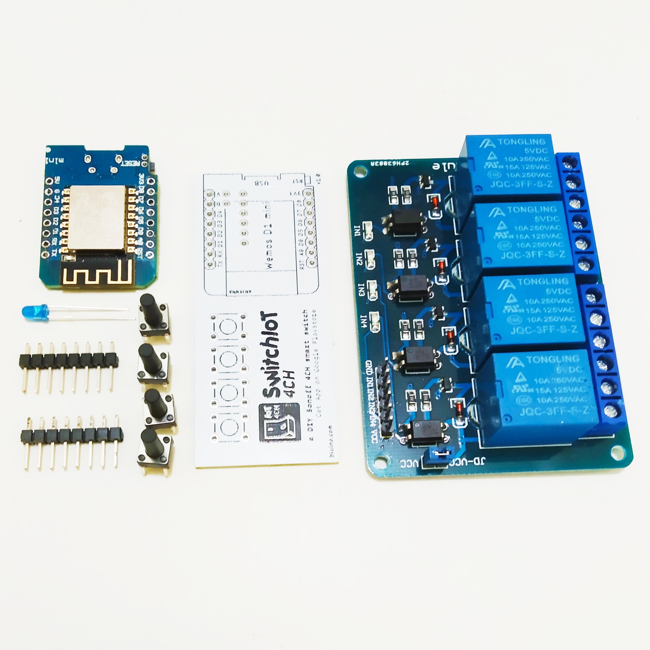
Here are the components that you will need to make this project:
(1) PCB SwitchIoT 4CH
(1) Relay Module 4 Channel
(1) Wemos D1 Mini Board (ESP8266)
(2) 1x8 Male Pin Header (Included with Wemos)
(4) Tact switch 6x6x12mm
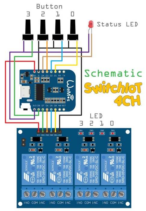
Circuit Diagram
Order PCB on PCBWAY
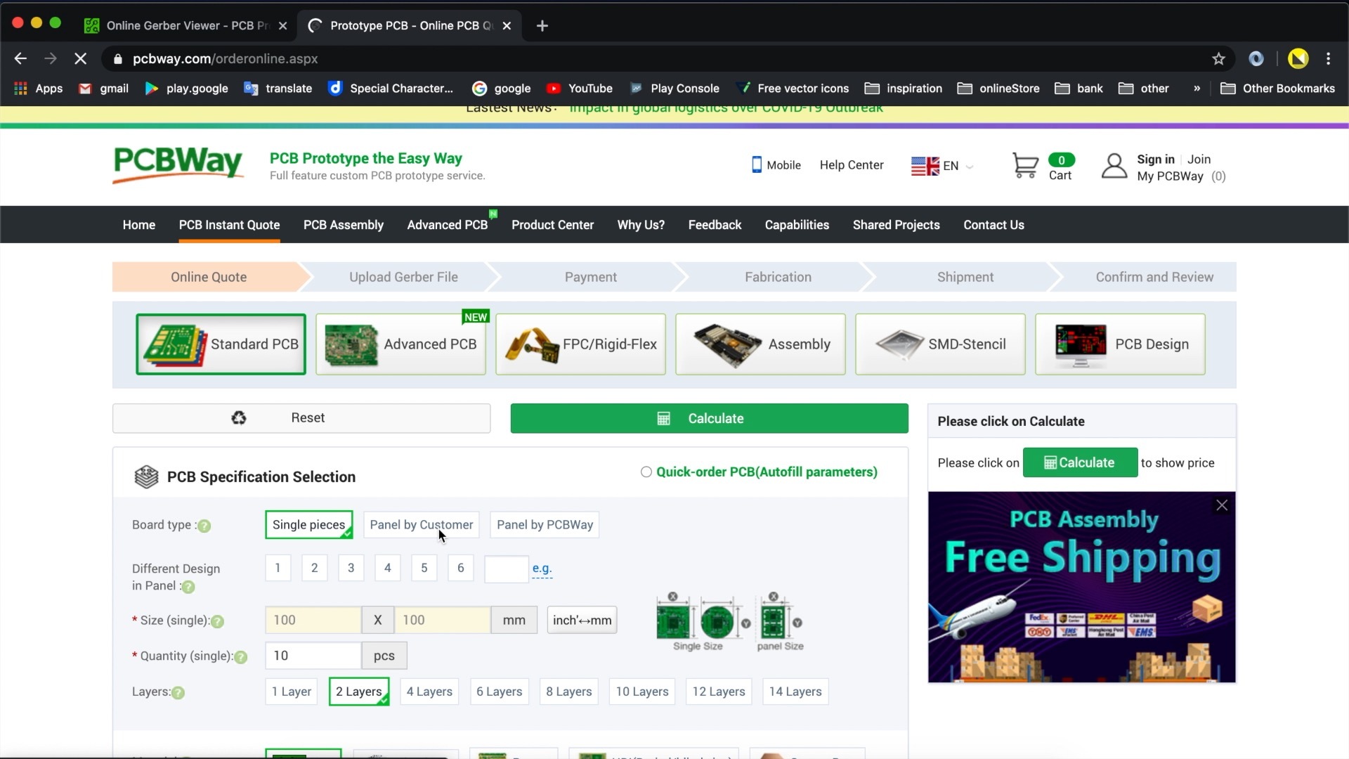
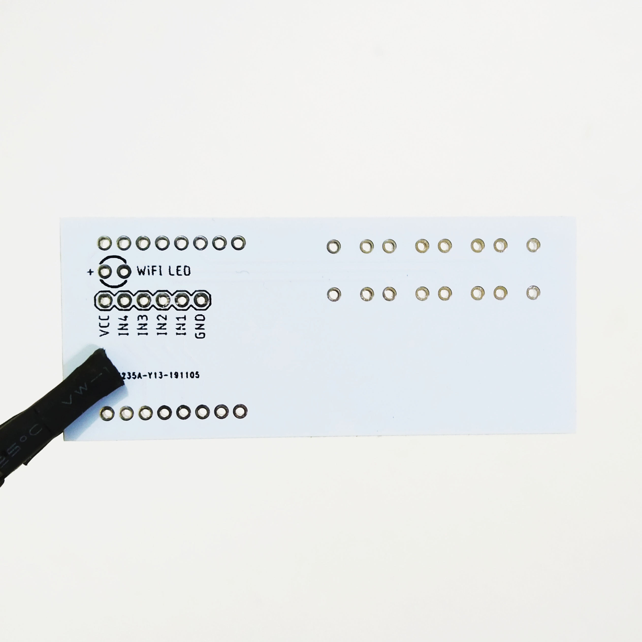
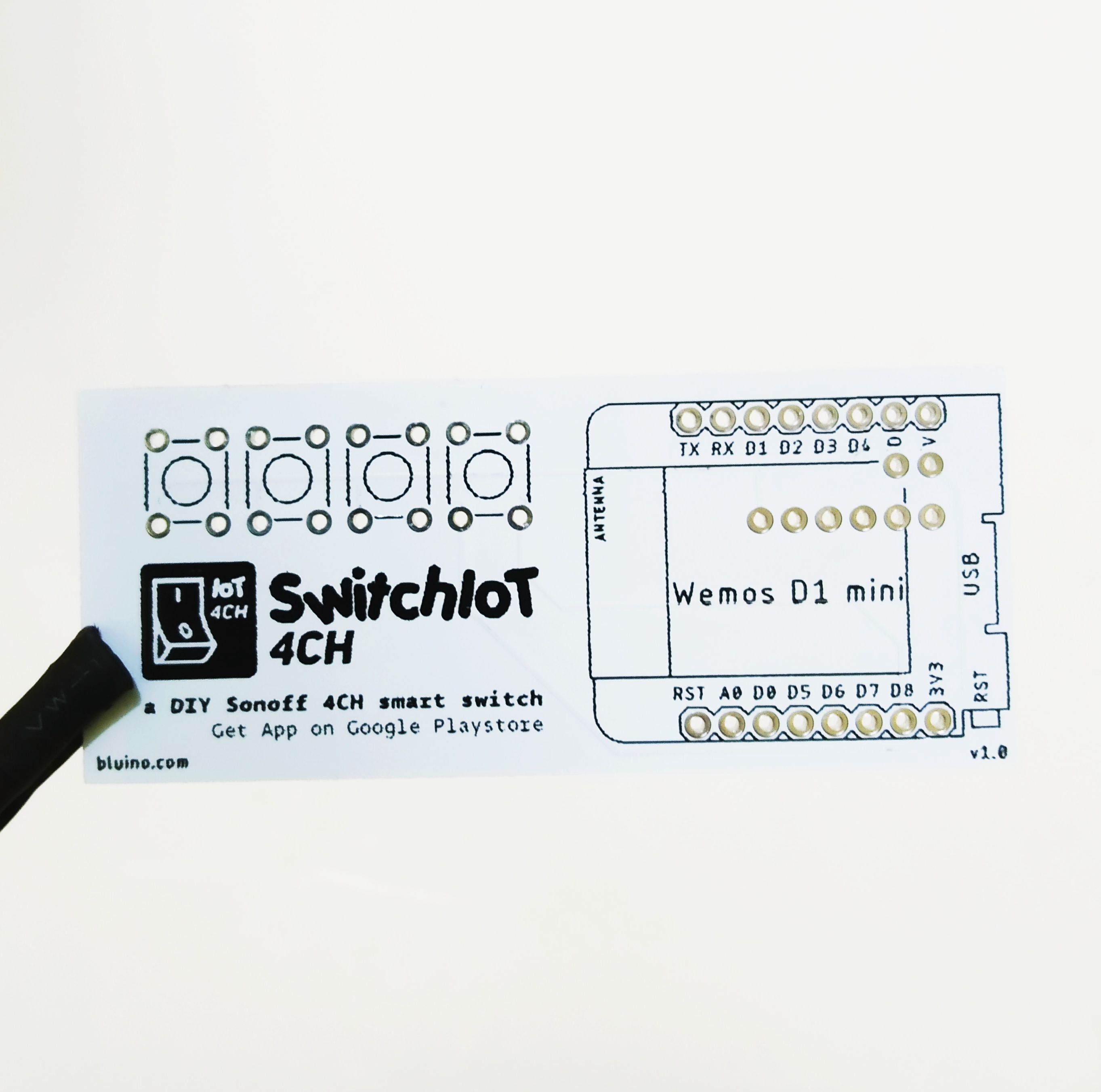
To make this project you need to order a prototype PCB on PCBWAY. To get PCB you can manufacture it directly on PCBWAY, how to order is very easy and you will get 10 Pcs PCB for $5 with very great PCB quality.
Step to Order:
1. SignUp/Log in on pcbway.com.
2. Open this PCB project link SwitchIoT 4CH.
3. Click Add to cart.
Soldering Wemos Board to PCB
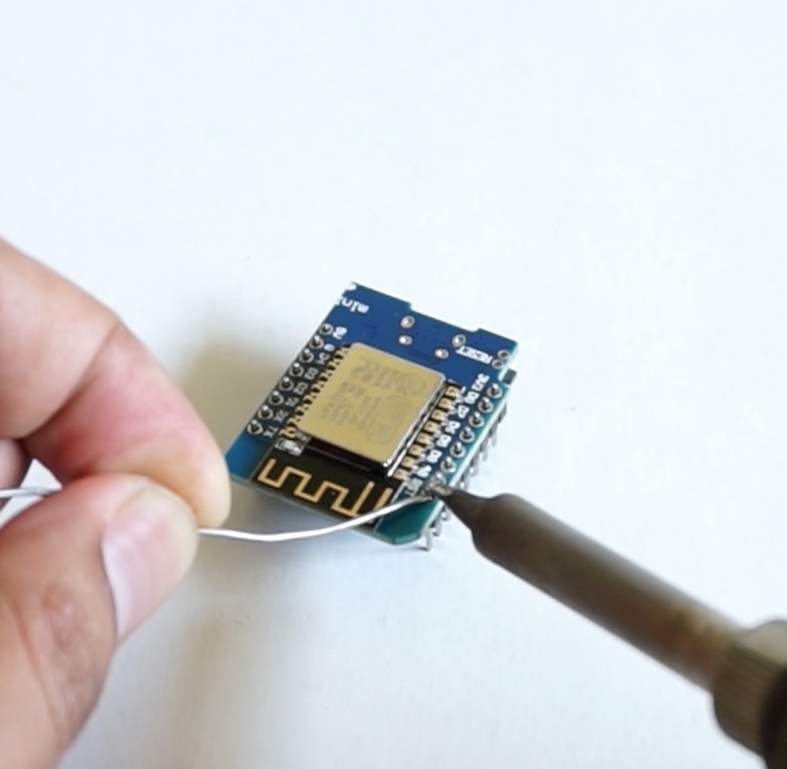
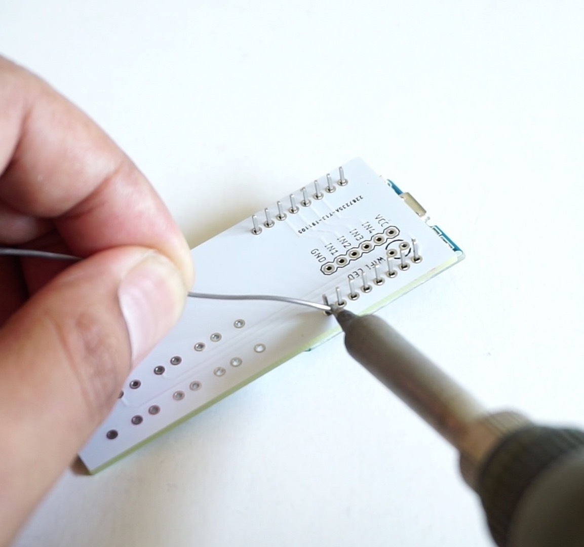

Solder two pin header to Wemos board.
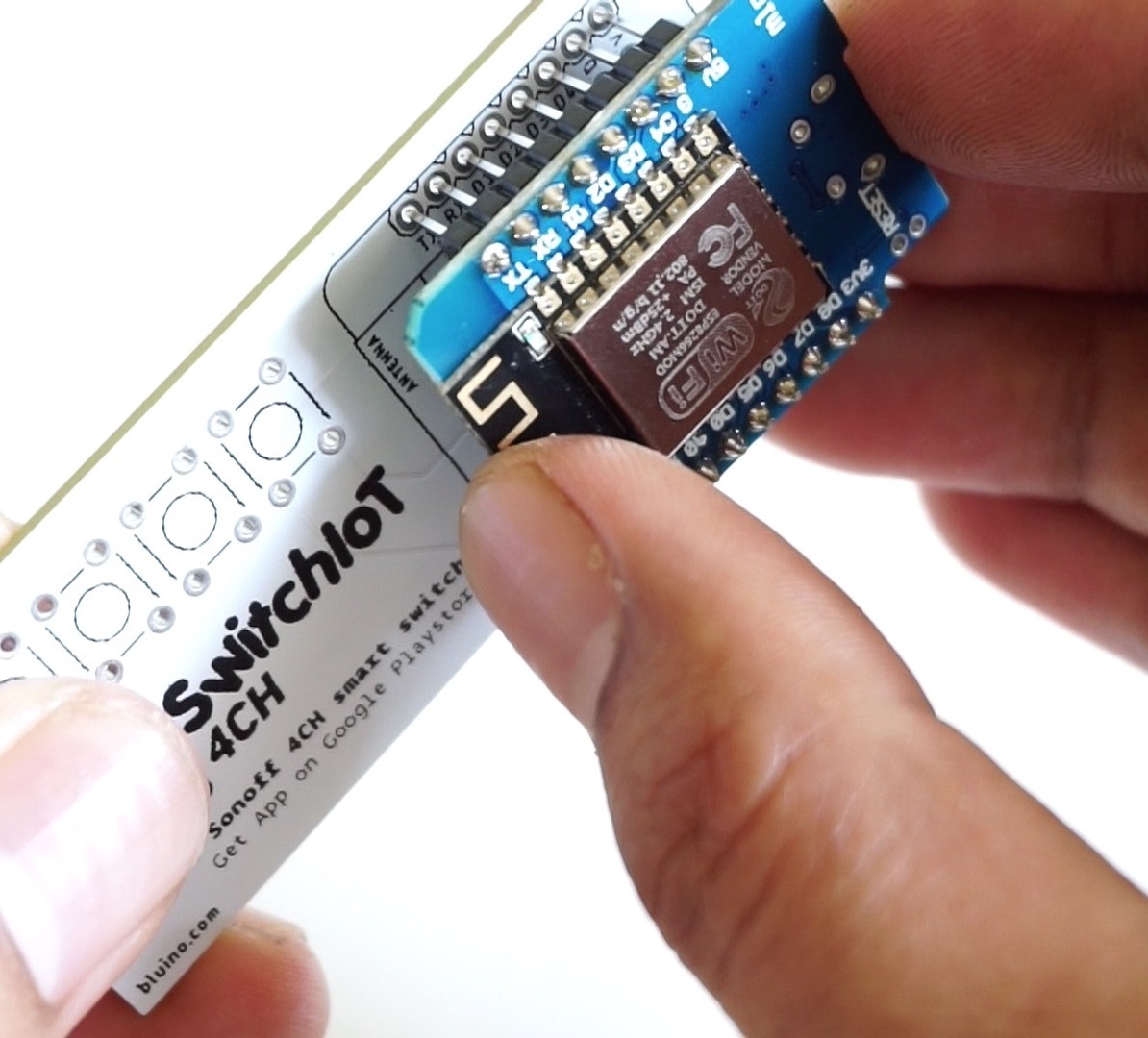
Put the Wemos D1 mini board on PCB in the correct direction and then solder it.
Note: When you have soldered, if you find that the Wemos board that you are using getting error cannot be programmed, you will definitely need to desoldering and replace Wemos board with another one. to prevent this you can jump to step 12 for uploading the firmware first before you solder.
Soldering Button
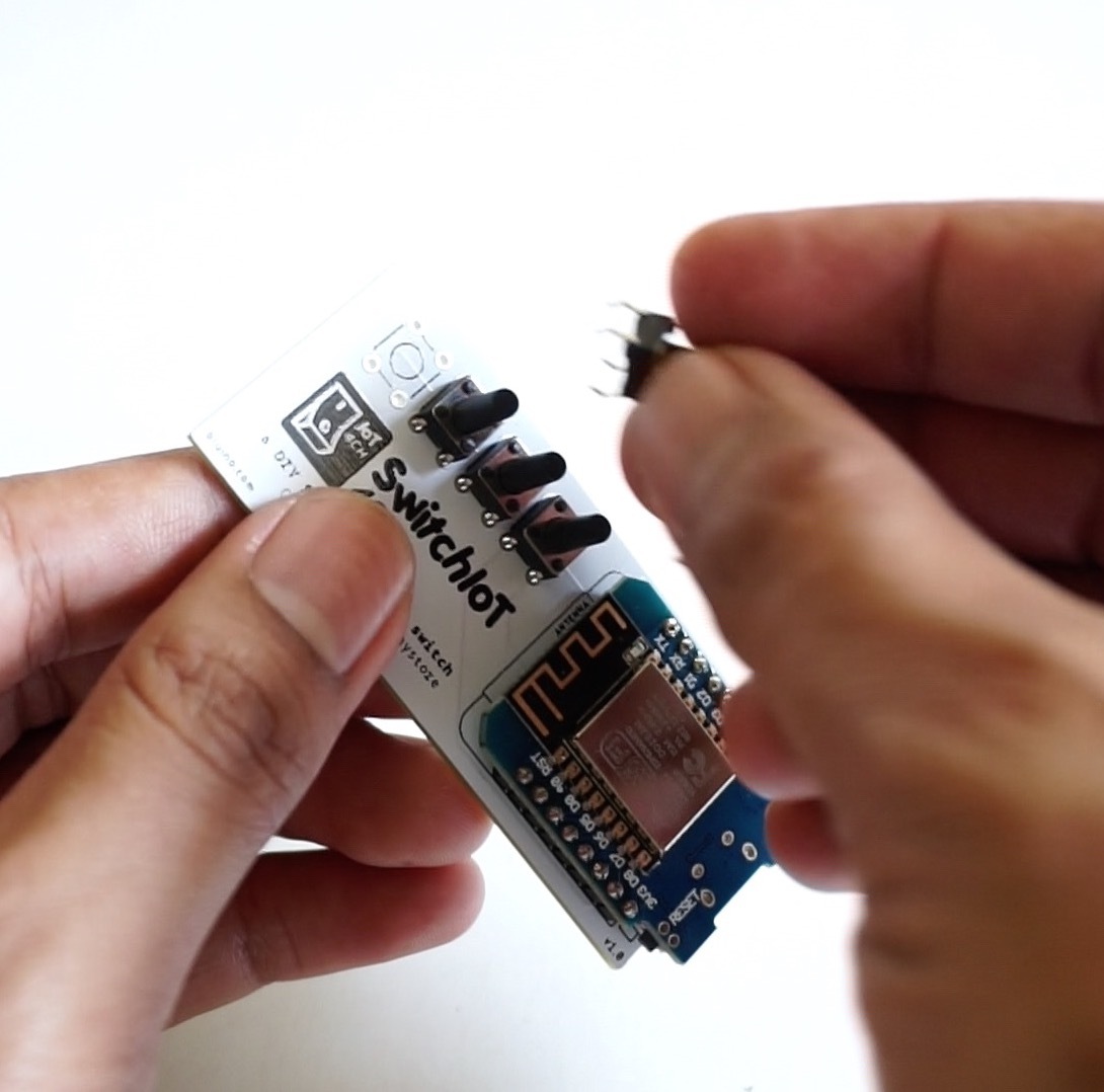
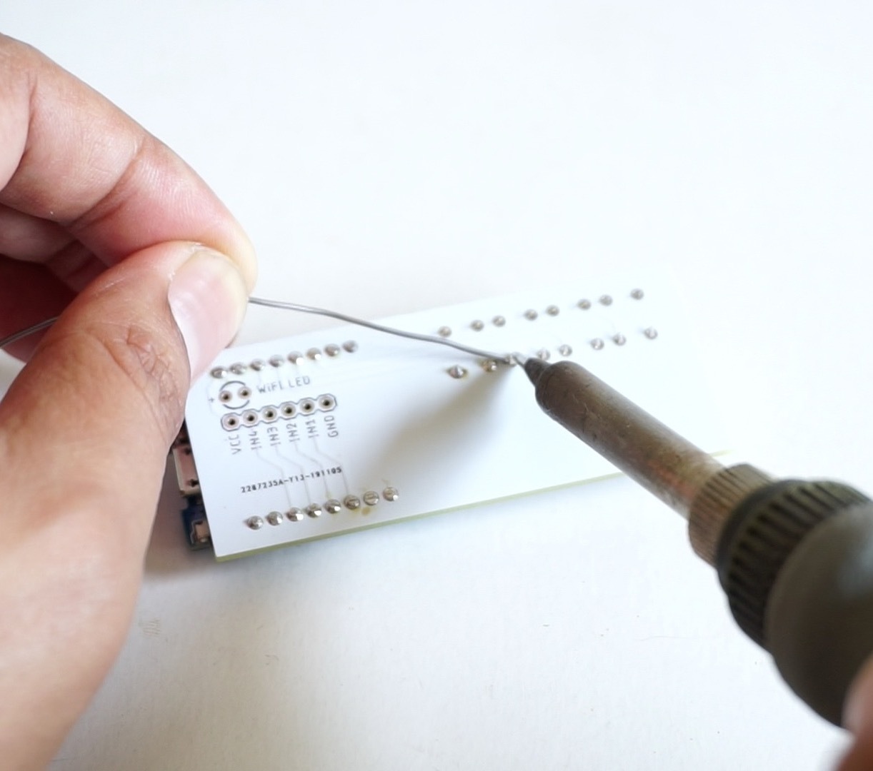
Placed 4 button into hole of PCB followed picture, then solder all legs of component on PCB.
Soldering LED
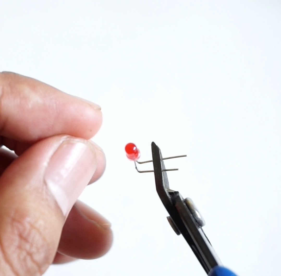
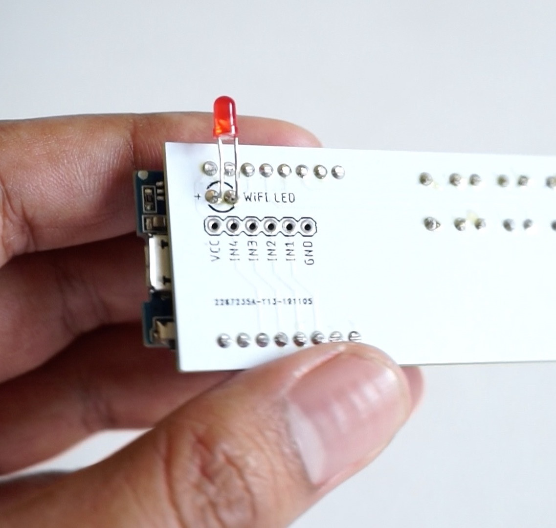
You need to bend about 90° the legs of LED and then solder it with a little hanging about 5mm, for details can see the picture. This meant that the LED could match the holes in the 3D printed case.
Assembling Relay Module
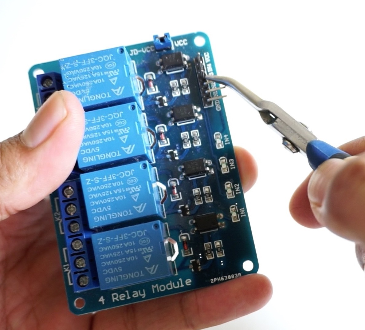
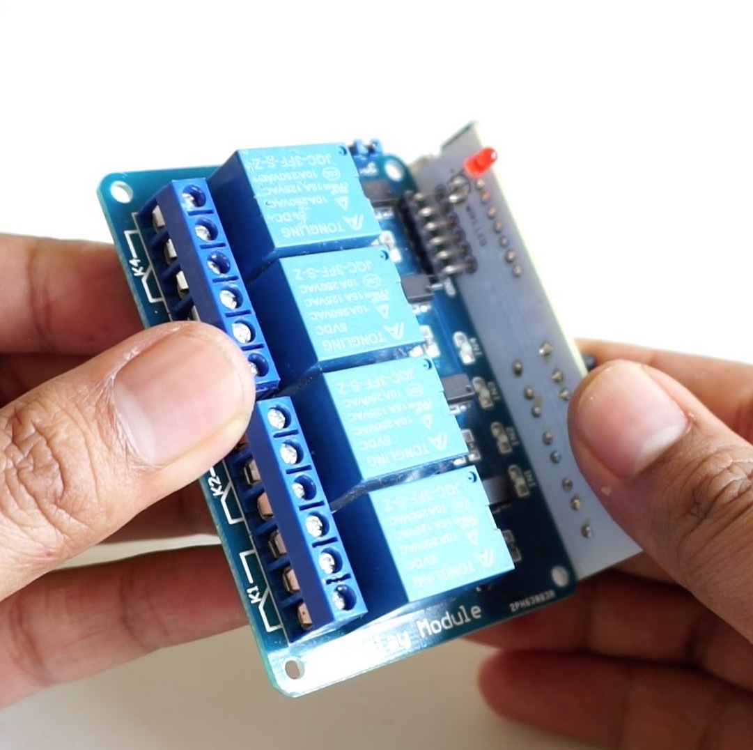
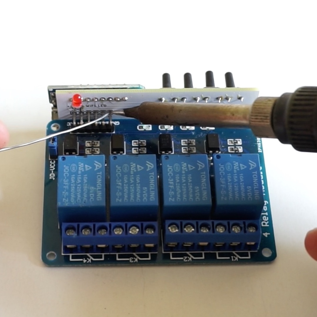
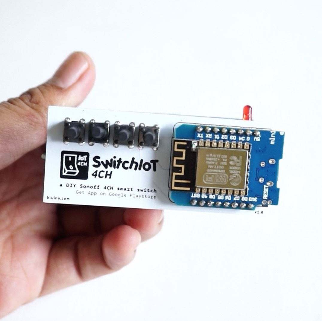
First bend 90° male pin header on the relay module to the outside (see picture), then point to the PCB hole from the back side and solder it (see picture), to be more stable also soldering on the opposite side of the PCB prototype.
Printing 3D Case
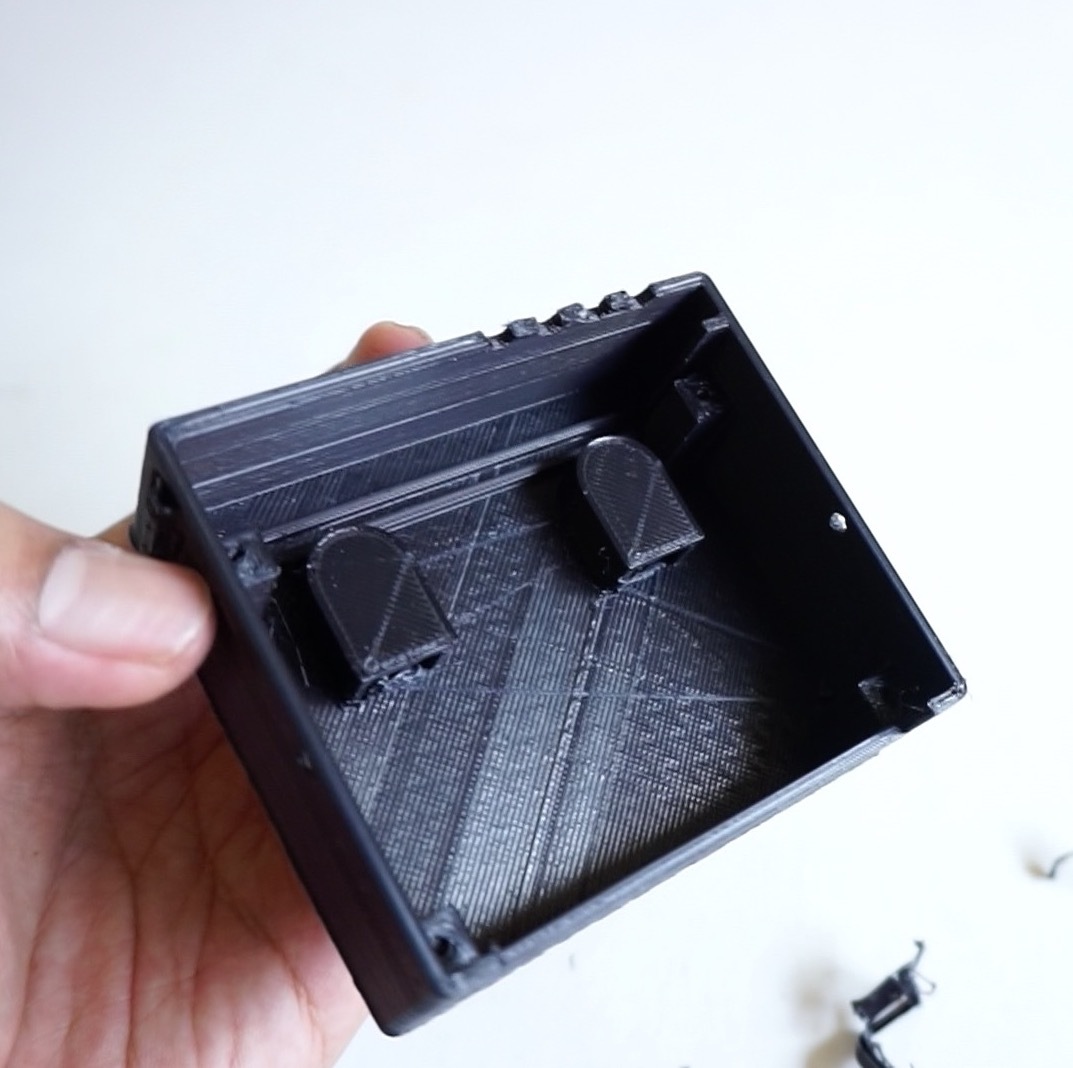
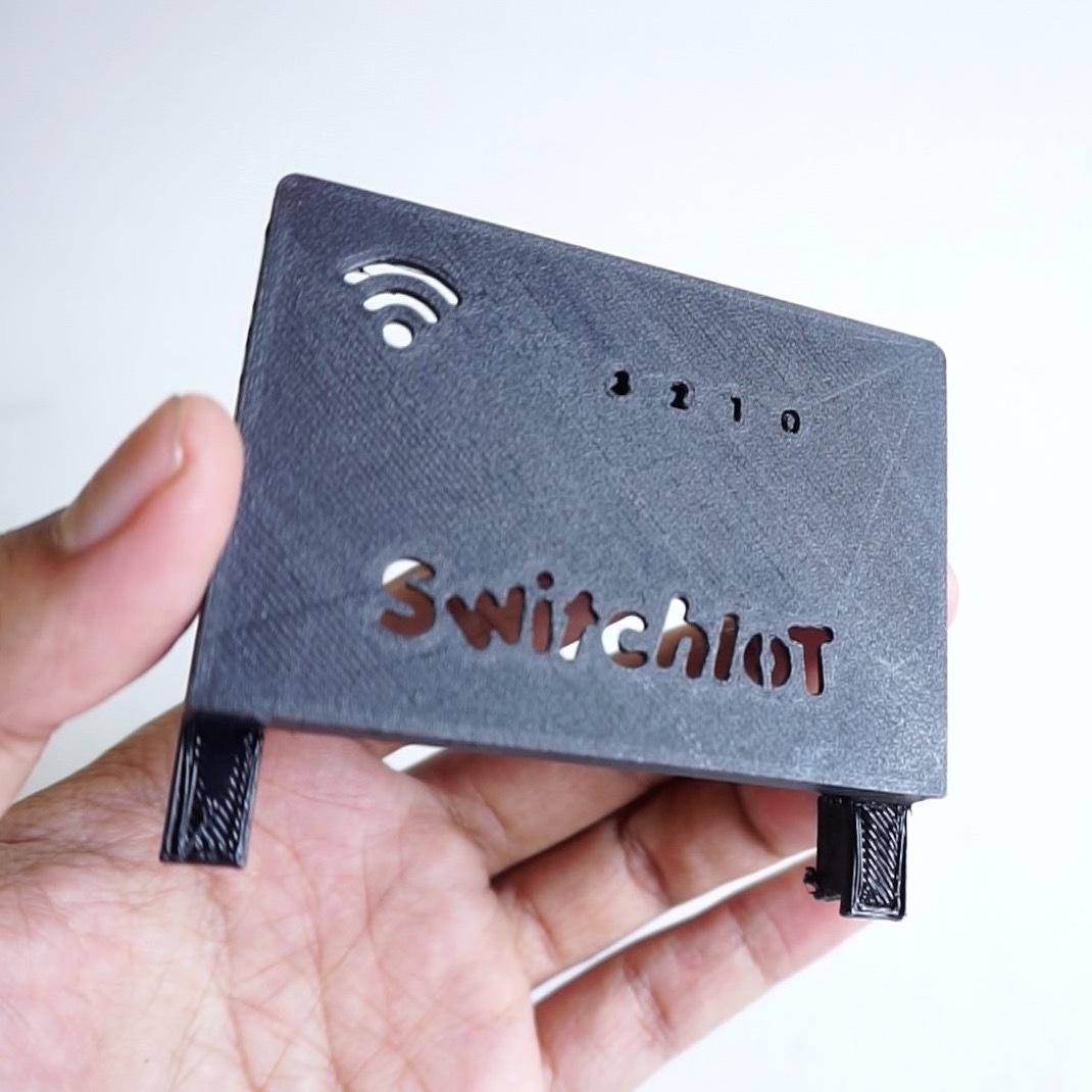
There are two parts, the bottom cover and top cover.
I realize this device is built using a relay module 4CH which does not have a standard PCB size, therefore maybe you will use a relay module PCB size that is different from my use. this has an impact on the not match between hadware with 3D printed case.
Here I shared some STL files (3D model file) for each of the different module relay PCB sizes, before you print the 3D model you should first check which model/size relay module PCB you are using.
Assembly All Together
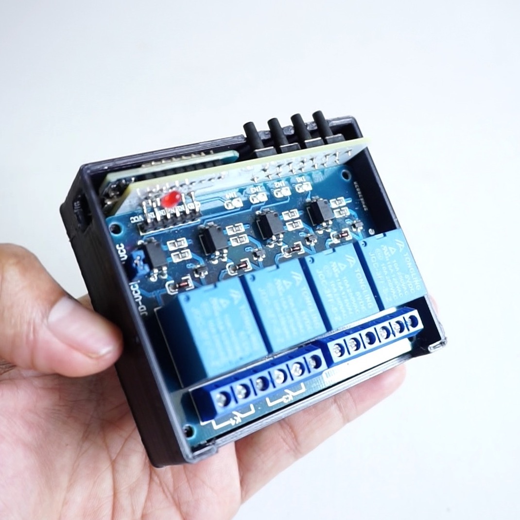
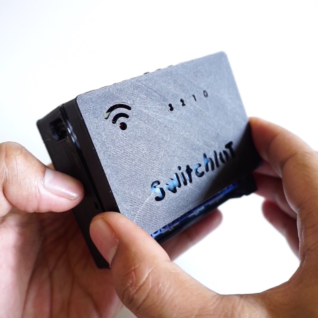
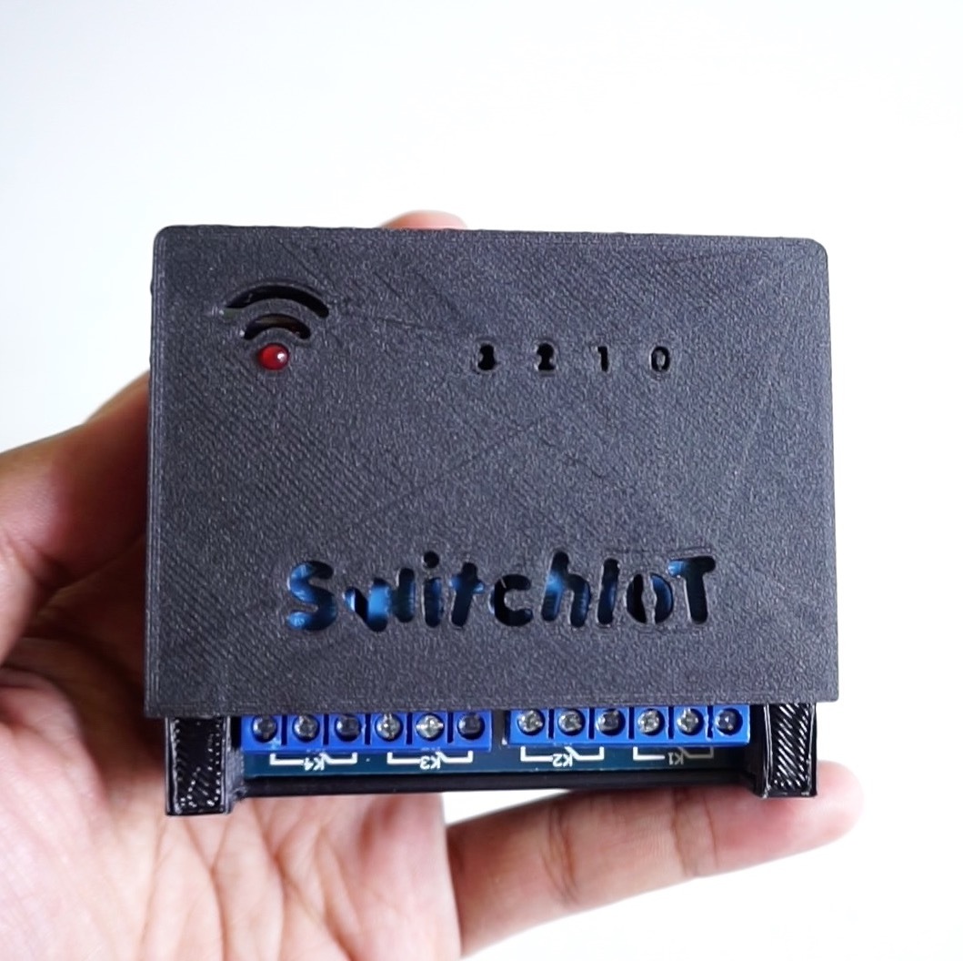
After you wait a few hours and finish printing 3D case, next you assembly hardware and 3D printed case together. You need four 1/4"x4mm screws, two screws are used to tighten the PCB with the bottom cover and other two screws are used to tighten the top cover and the bottom cover.
Set Up Blynk App


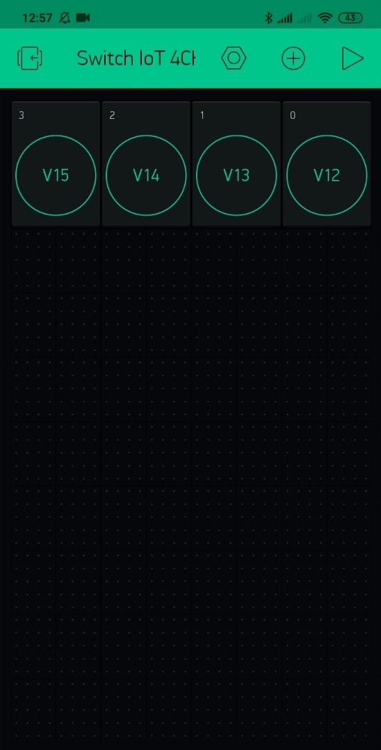
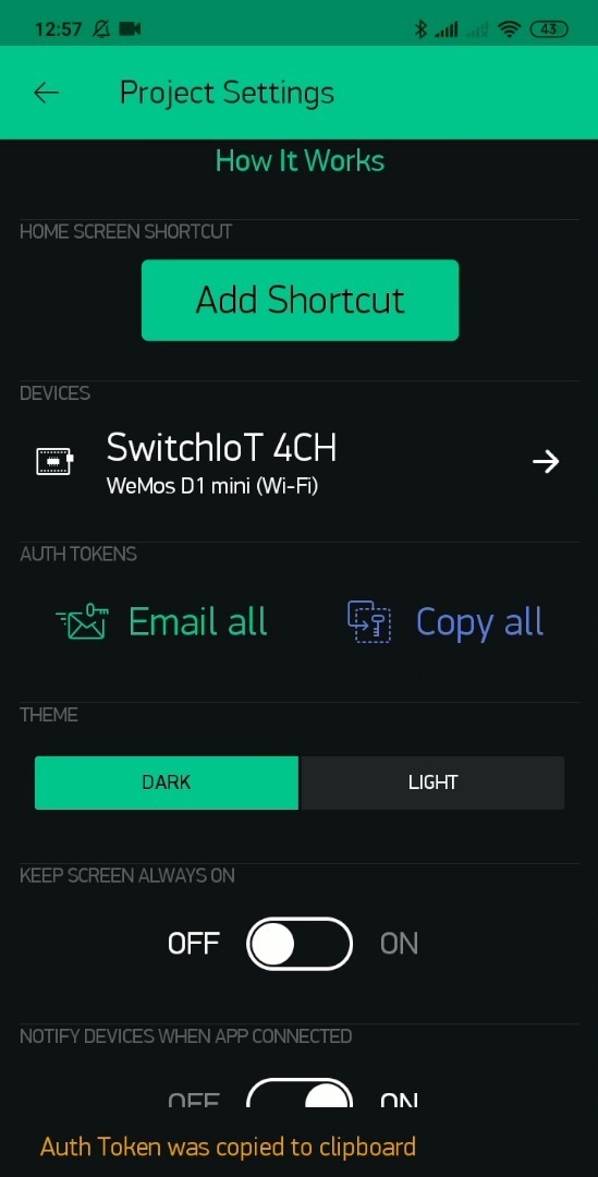
Install Blynk app from Google Playstore :
To configuration Blynk interface for Switch IoT 4CH project, you just need clone this project by scanning a given QR link.
Copy to the clipboard the Auth Token that generated of your cloning Switch IoT 4CH project, which will be pasted into the ESP8266 Loader app.
Set Up ESP8266 Loader App
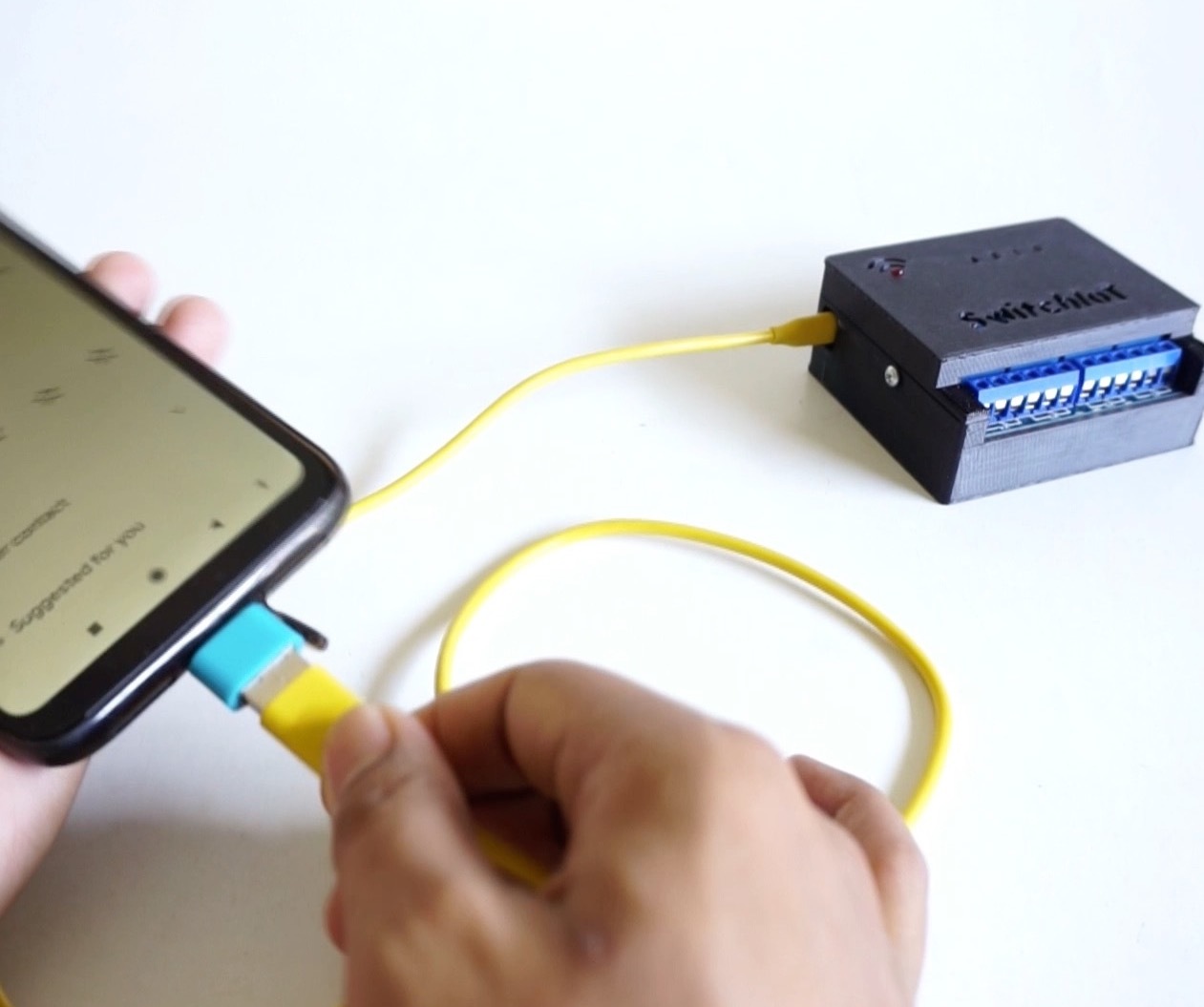
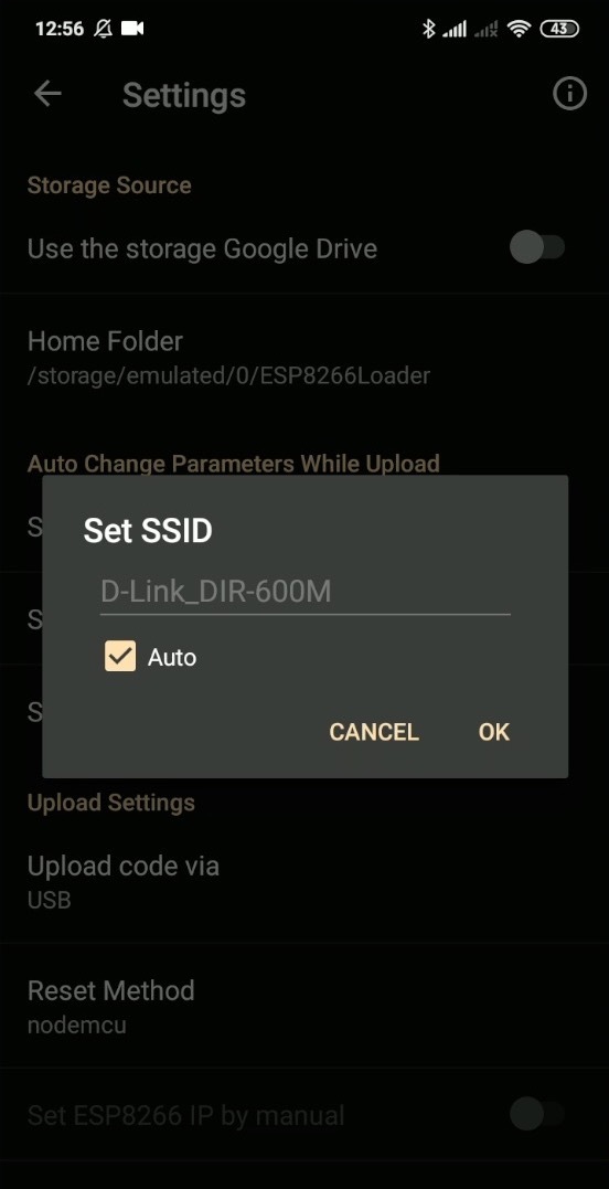
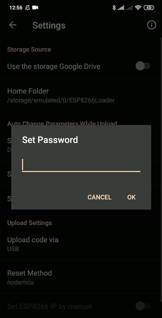
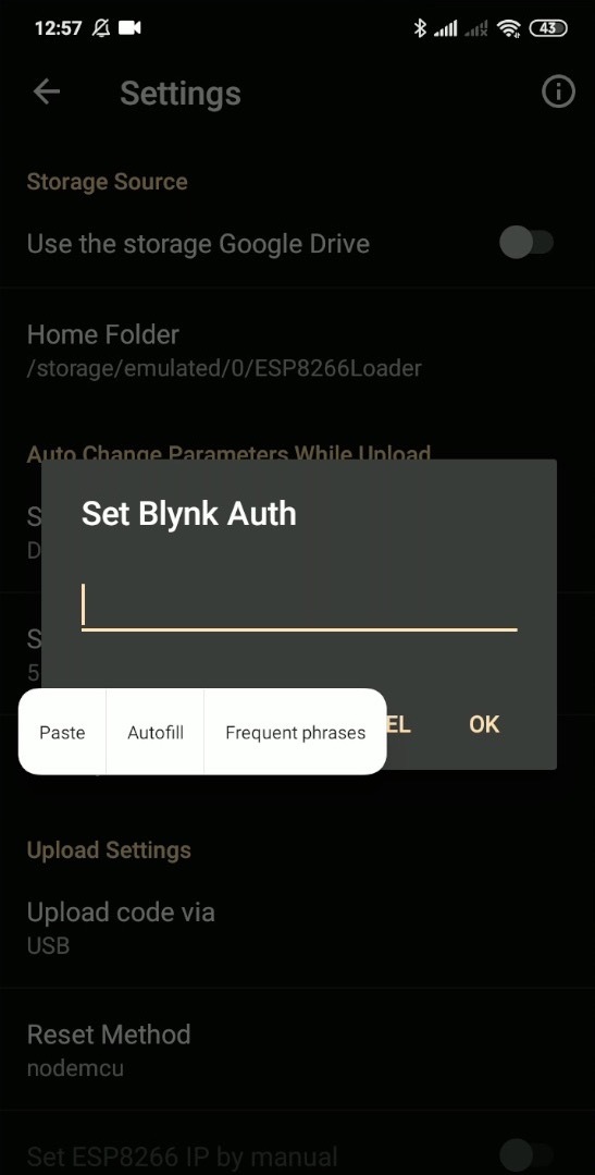
You will need an OTG adapter so you can upload from an Android smartphone to the Wemos board.
Install ESP8266 Loader app from Google Playstore :
Open the app, go to the Setting menu then configure some parameters:
Set SSID : your SSID name of network will be used
Set Password : your password of SSID
Set Blynk Auth : your token that generated of cloning Switch IoT 4CH project
Upload the Firmware
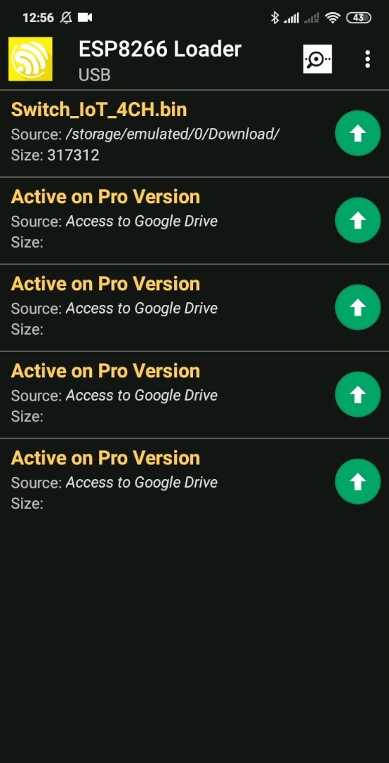
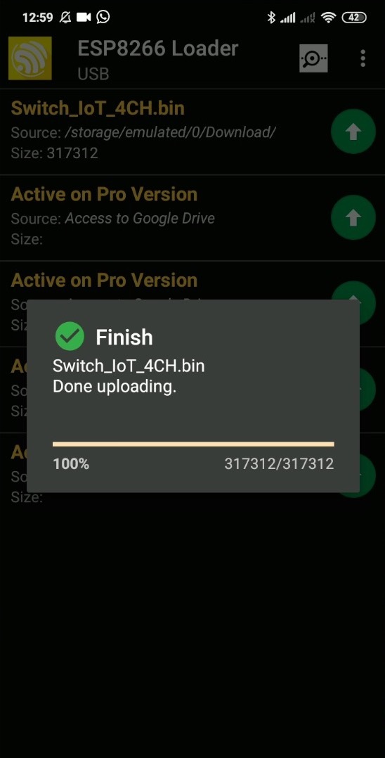
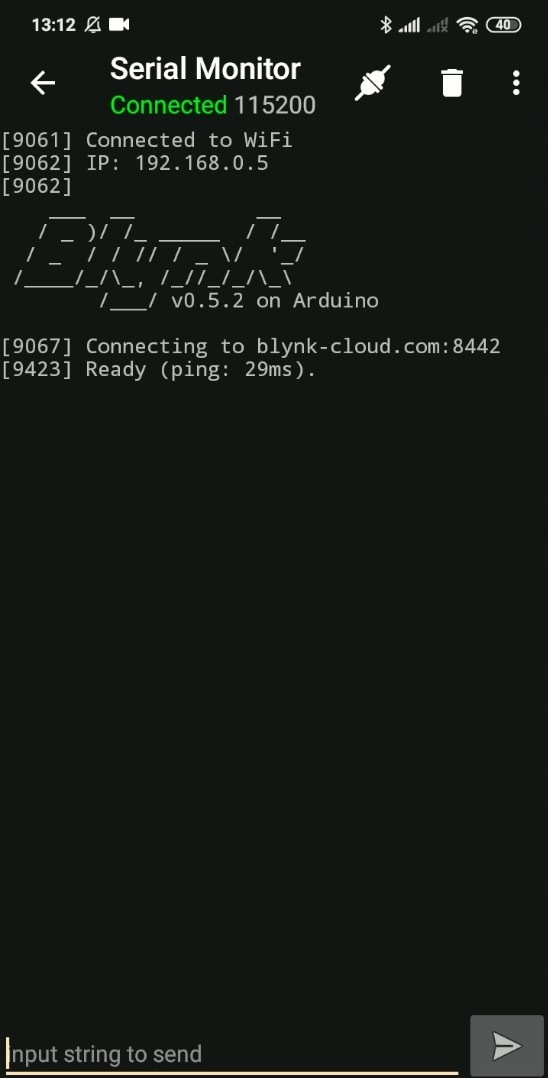
After complete setting for SSID, Password & Blynk token, download the firmware file below into your smartphone's directory.
Open the ESP8266 Loader app, select the firmware file Switch_IoT_4CH.bin, then press upload icon to write firmware to Wemos board.
When finish uploading firmware, next you can open the Serial Monitor to check whether the device is connected to the Blynk server, or you can see the wifi LED will light if it is connected to the Blynk server.
If you use computer to upload sketch into Wemos board, copy and paste the code bellow to Arduino IDE and upload it.
#define BLYNK_PRINT Serial
#include <ESP8266WiFi.h>
#include <BlynkSimpleEsp8266.h>
#include <ESP8266mDNS.h>  // For OTA with ESP8266
#include <WiFiUdp.h>  // For OTA
#include <ArduinoOTA.h>  // For OTA


BlynkTimer timer;

void checkPhysicalButton();

int relay0State = HIGH;
int pushButton0State = HIGH;

int relay1State = HIGH;
int pushButton1State = HIGH;

int relay2State = HIGH;
int pushButton2State = HIGH;

int relay3State = HIGH;
int pushButton3State = HIGH;


#define AUTH "$your_auth_maximum_32_characters"             // You should get Auth Token in the Blynk App.
#define WIFI_SSID "$your_ssid_maximum_32_characters"        //Enter Wifi Name
#define WIFI_PASS "$your_pswd_maximum_32_characters"        //Enter wifi Password


#define SERVER "blynk-cloud.com "                // Comment-out if use Blynk hosted cloud service
#define PORT 8442

#define PUSH_BUTTON_0      5   //D1
#define PUSH_BUTTON_1      4   //D2
#define PUSH_BUTTON_2      0   //D3
#define PUSH_BUTTON_3      15  //D8

#define RELAY_PIN_0    16   //D0
#define RELAY_PIN_1    14   //D5
#define RELAY_PIN_2    12   //D6
#define RELAY_PIN_3    13   //D7

#define LED_WIFI       2    //D4

#define VPIN_BUTTON_0    V12
#define VPIN_BUTTON_1    V13
#define VPIN_BUTTON_2    V14
#define VPIN_BUTTON_3    V15

#define OTA_HOSTNAME "SwitchIoT 4CH"


BLYNK_CONNECTED() {
  // Request the latest state from the server

  Blynk.syncVirtual(VPIN_BUTTON_0);
  Blynk.syncVirtual(VPIN_BUTTON_1);
  Blynk.syncVirtual(VPIN_BUTTON_2);
  Blynk.syncVirtual(VPIN_BUTTON_3);

 // Alternatively, you could override server state using:
 // Blynk.virtualWrite(VPIN_BUTTON_0, relay0State);
 // Blynk.virtualWrite(VPIN_BUTTON_1, relay1State);
 // Blynk.virtualWrite(VPIN_BUTTON_2, relay2State);
 // Blynk.virtualWrite(VPIN_BUTTON_3, relay3State);

}

// When App button is pushed - switch the state


BLYNK_WRITE(VPIN_BUTTON_0) {
  relay0State = param.asInt();
  digitalWrite(RELAY_PIN_0, relay0State);
}
BLYNK_WRITE(VPIN_BUTTON_1) {
  relay1State = param.asInt();
  digitalWrite(RELAY_PIN_1, relay1State);
}

BLYNK_WRITE(VPIN_BUTTON_2) {
  relay2State = param.asInt();
  digitalWrite(RELAY_PIN_2, relay2State);
}
BLYNK_WRITE(VPIN_BUTTON_3) {
  relay3State = param.asInt();
  digitalWrite(RELAY_PIN_3, relay3State);
}

void checkPhysicalButton() {

  if (digitalRead(PUSH_BUTTON_0) == LOW) {
    // pushButton0State is used to avoid sequential toggles
    if (pushButton0State != LOW) {

      // Toggle Relay state
      relay0State = !relay0State;
      digitalWrite(RELAY_PIN_0, relay0State);

      // Update Button Widget
      Blynk.virtualWrite(VPIN_BUTTON_0, relay0State);
    }
    pushButton0State = LOW;
  } else {
    pushButton0State = HIGH;
  }

  if (digitalRead(PUSH_BUTTON_1) == LOW) {
    // pushButton1State is used to avoid sequential toggles
    if (pushButton1State != LOW) {

      // Toggle Relay state
      relay1State = !relay1State;
      digitalWrite(RELAY_PIN_1, relay1State);

      // Update Button Widget
      Blynk.virtualWrite(VPIN_BUTTON_1, relay1State);
    }
    pushButton1State = LOW;
  } else {
    pushButton1State = HIGH;
  }

  if (digitalRead(PUSH_BUTTON_2) == LOW) {
    // pushButton2State is used to avoid sequential toggles
    if (pushButton2State != LOW) {

      // Toggle Relay state
      relay2State = !relay2State;
      digitalWrite(RELAY_PIN_2, relay2State);

      // Update Button Widget
      Blynk.virtualWrite(VPIN_BUTTON_2, relay2State);
    }
    pushButton2State = LOW;
  } else {
    pushButton2State = HIGH;
  }

  if (digitalRead(PUSH_BUTTON_3) == HIGH) {
    // pushButton3State is used to avoid sequential toggles
    if (pushButton3State != LOW) {

      // Toggle Relay state
      relay3State = !relay3State;
      digitalWrite(RELAY_PIN_3, relay3State);

      // Update Button Widget
      Blynk.virtualWrite(VPIN_BUTTON_3, relay3State);
    }
    pushButton3State = LOW;
  } else {
    pushButton3State = HIGH;
  }
}


void setup() {
  Serial.begin(115200);
  Blynk.begin(AUTH, WIFI_SSID, WIFI_PASS,"blynk-cloud.com", 8442);
  ArduinoOTA.setHostname(OTA_HOSTNAME);  // For OTA - Use your own device identifying name
  ArduinoOTA.begin();  // For OTA

  pinMode(RELAY_PIN_0, OUTPUT);
  pinMode(PUSH_BUTTON_0, INPUT_PULLUP);
  digitalWrite(RELAY_PIN_0, relay0State);


  pinMode(RELAY_PIN_1, OUTPUT);
  pinMode(PUSH_BUTTON_1, INPUT_PULLUP);
  digitalWrite(RELAY_PIN_1, relay1State);


  pinMode(RELAY_PIN_2, OUTPUT);
  pinMode(PUSH_BUTTON_2, INPUT_PULLUP);
  digitalWrite(RELAY_PIN_2, relay2State);


  pinMode(RELAY_PIN_3, OUTPUT);
  pinMode(PUSH_BUTTON_3, INPUT);
  digitalWrite(RELAY_PIN_3, relay3State);

  pinMode(LED_WIFI, OUTPUT);

  // Setup a function to be called every 100 ms
  timer.setInterval(500L, checkPhysicalButton);
}

void loop() {
  if (Blynk.connected()) digitalWrite(LED_WIFI, LOW);
  else digitalWrite(LED_WIFI, HIGH);

  Blynk.run();
  ArduinoOTA.handle();  // For OTA
  timer.run();
}
Usage - Wiring Diagram for 4 Lights
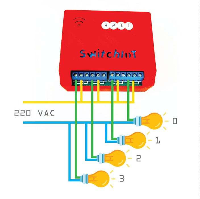
This Switch IoT 4CH device have the functions basic, you can remote turn on/off home appliance from anywhere at any time.
See to the picture, is s sample wiring diagram of the usage to turn on/off 4 lights.
Play and Control Your Home Appliance
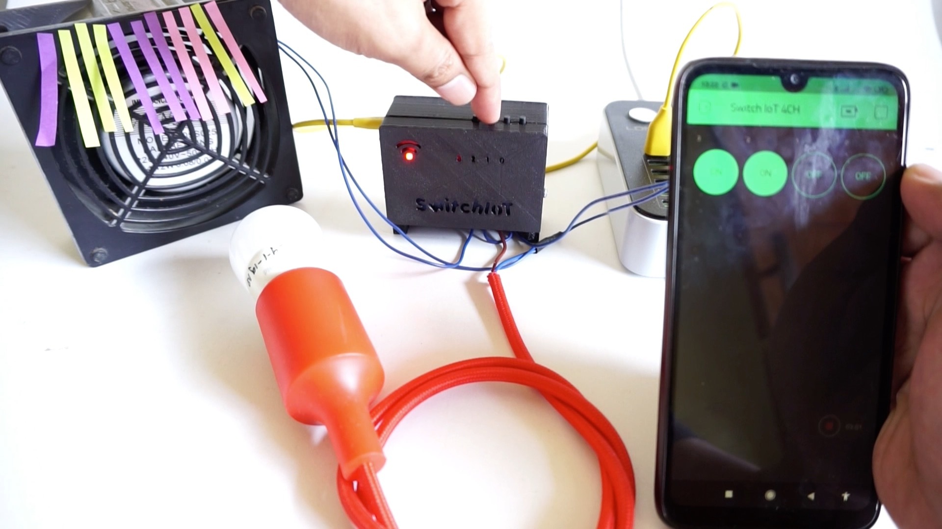
In the Blynk app open the Switch IoT 4CH project then press play, and now you can control your home appliances that are connected to the Switch IoT device from anywhere with your smartphone, you can also control the ON/OFF relay locally by pressing the button.
Enjoy
Hopefully you enjoy it. If you do and done, please share "I Made it!" to let me know how much is worked. Share the link, like and subscribe. As always, if you have any questions please let me know!