Make: Bluetooth Controlled RGB Led T-shirt With Splat PLC
7106 Views, 29 Favorites, 0 Comments
Make: Bluetooth Controlled RGB Led T-shirt With Splat PLC
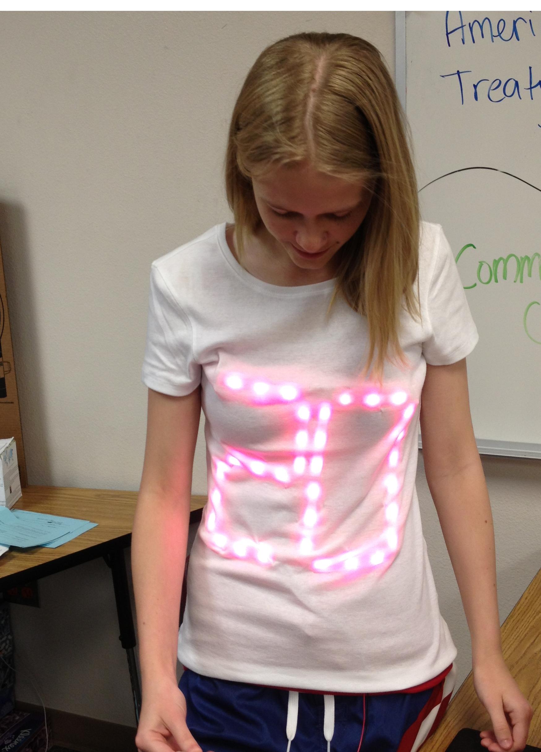
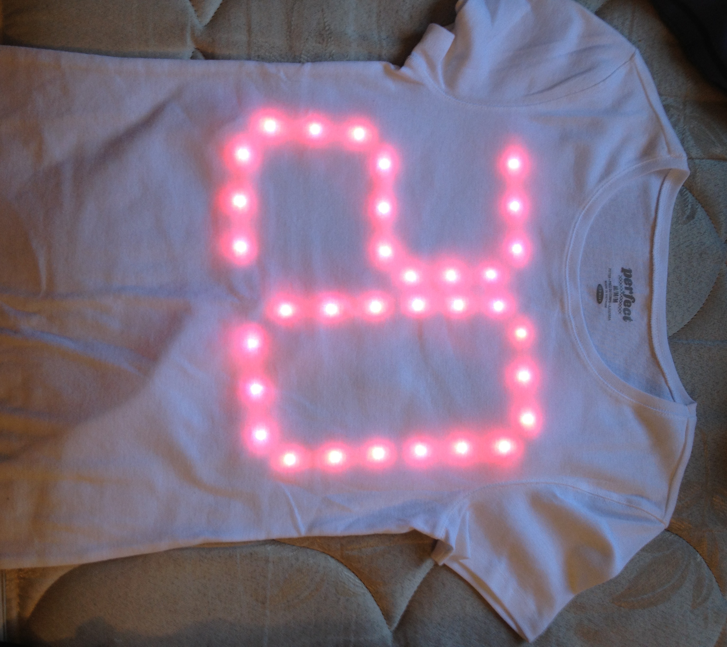
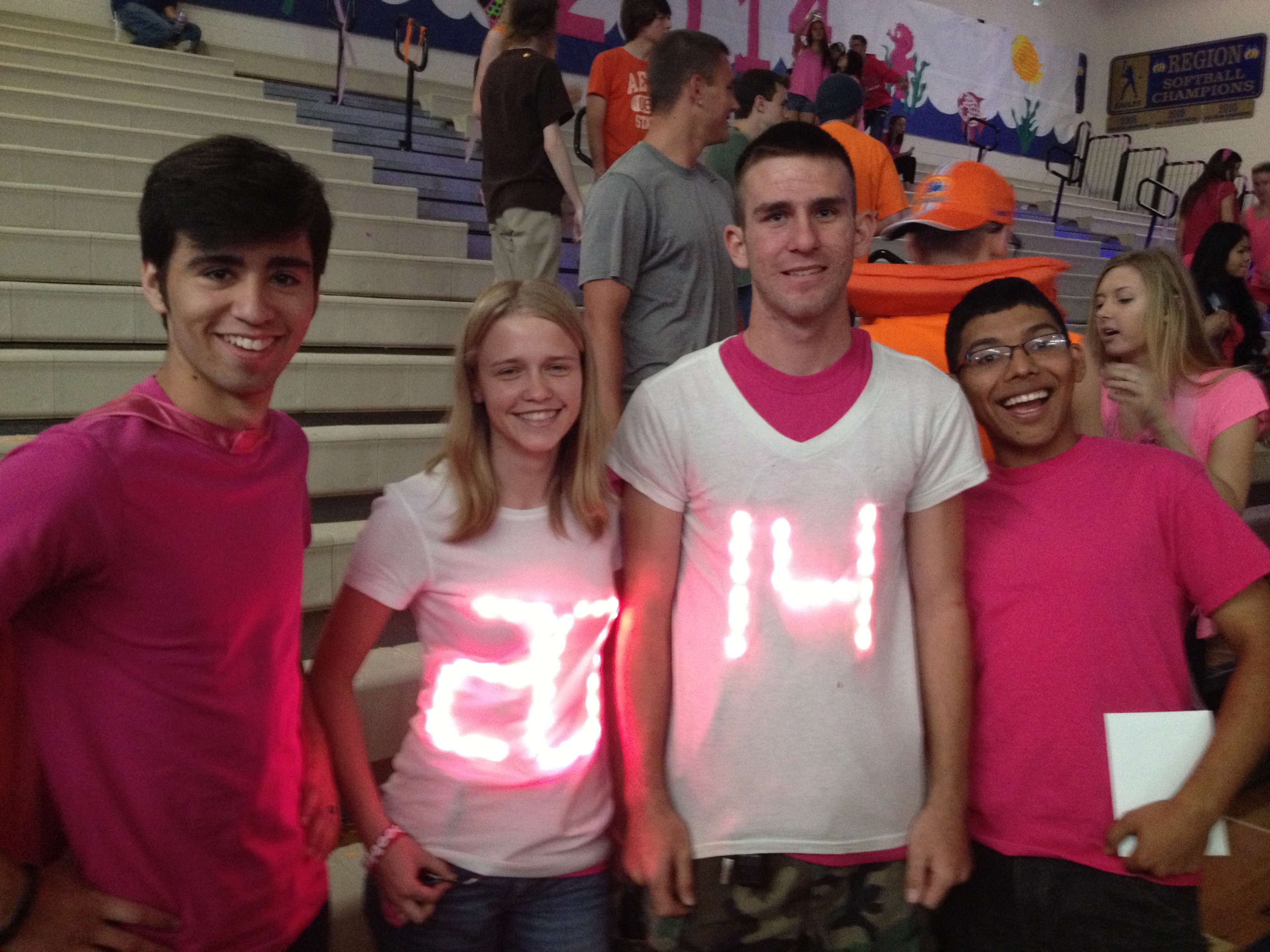
Everyone has that one shirt they love to wear, but who can say they have a shirt that lights up? Better yet who can say they have a shirt that lights up AND is controlled from their android device! I will give you step by step instructions on how to easily make your own light up shirt.
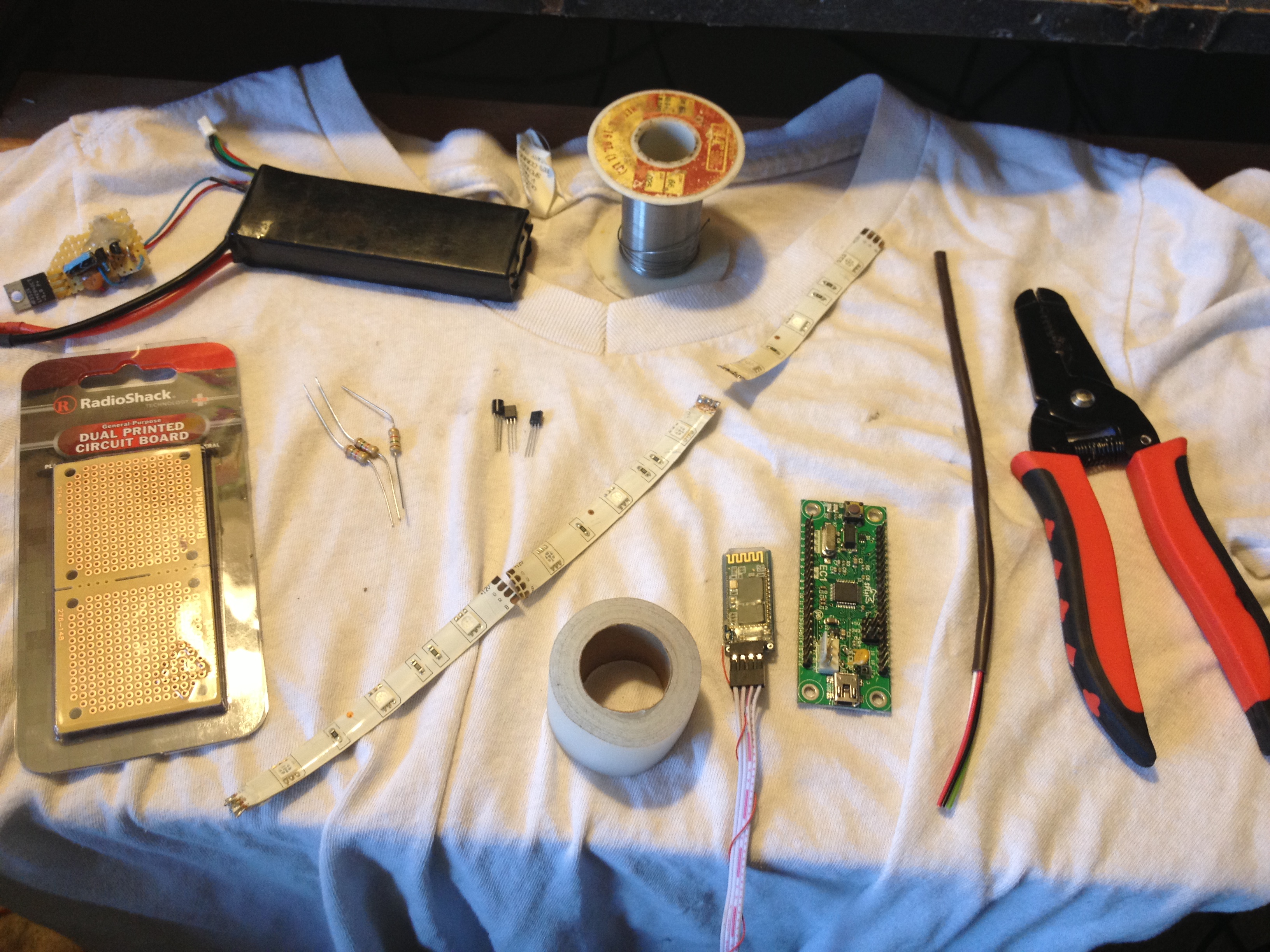
Parts you will need:
1X reel of RGB LEDs (available on amazon for $15)
3X 2n2222a NPN transistor
3X 1K Ohm resistor
1X portable power supply with 5v and 12v output (some sort of battery pack, AA or AAA will work, the LEDs pull 60mA per set of 3 @12v)
1X EC1 Splat PLC available on the Splat Controls website
1X the Bluetooth Serial Port Module for Arduino
1X perf board
Needle and thread
Wire
Solder and soldering iron
Clear tape
White T-shirt
Wire cutters
A computer running SPLat/PC, the free SPLat programming environment (IDE)
Time required: About 2-3 Hours
Cut Your LEDs to Size
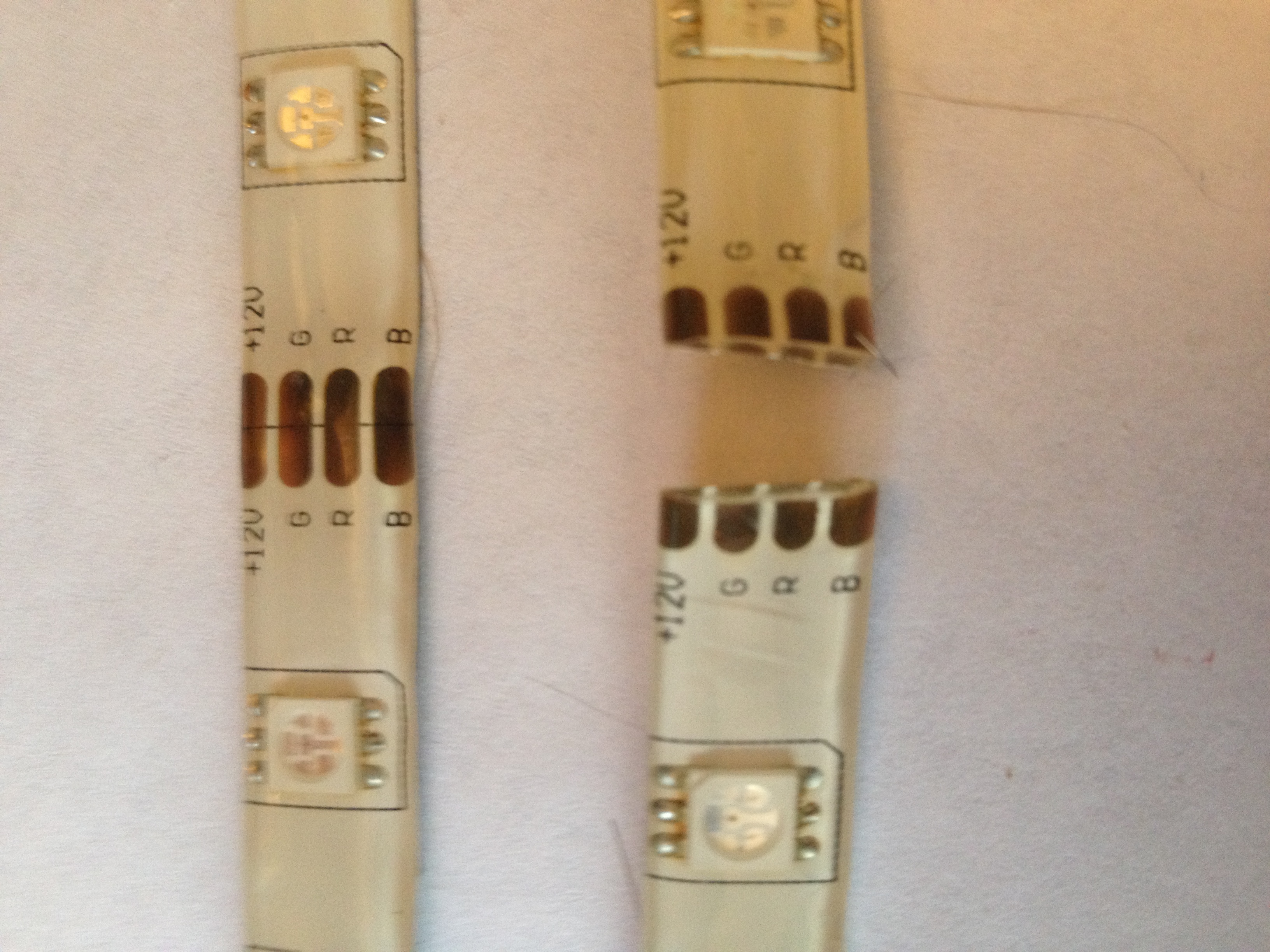
*Because I already have the number 14 made i will show the first half of the steps with the number 20 and the last half with 14 but the process is the exact same with both.*
Now once you know how many strips you need you can cut along the designated spots (every three leds). Make sure to leave copper pads on each strip.
Prepare for Soldering Together
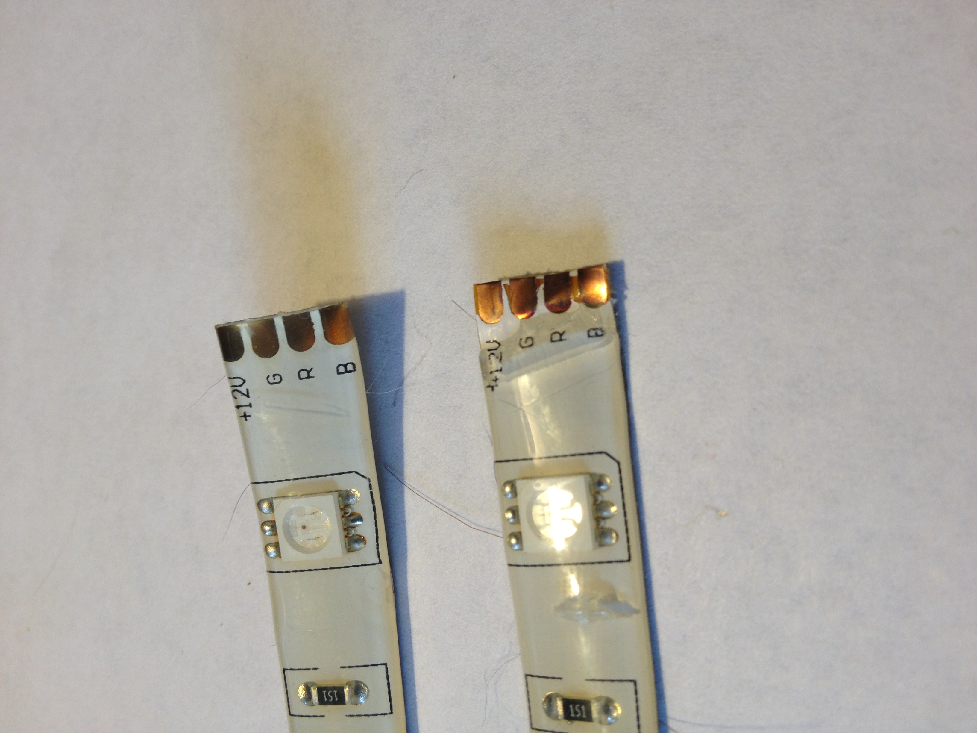
To do this i used a box cutter and carefully without cutting the bottom copper strip or your fingers, put a slit in the plastic just past the copper pads.
You should now be able to peal off the plastic from the ends.
Begin Soldering Your Led Patern
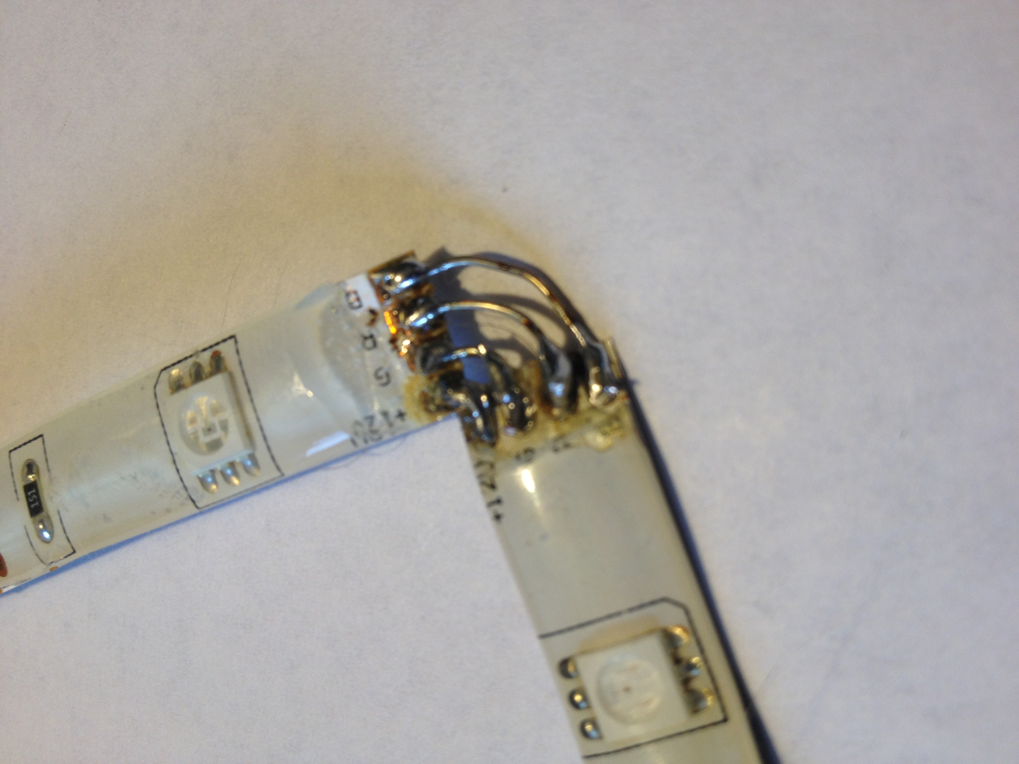
Now place a solder bead on each pad and solder the corners together, the other 3 connections will be made using wire bent into a right angle.
R to R
G to G
B to B
12v to 12v
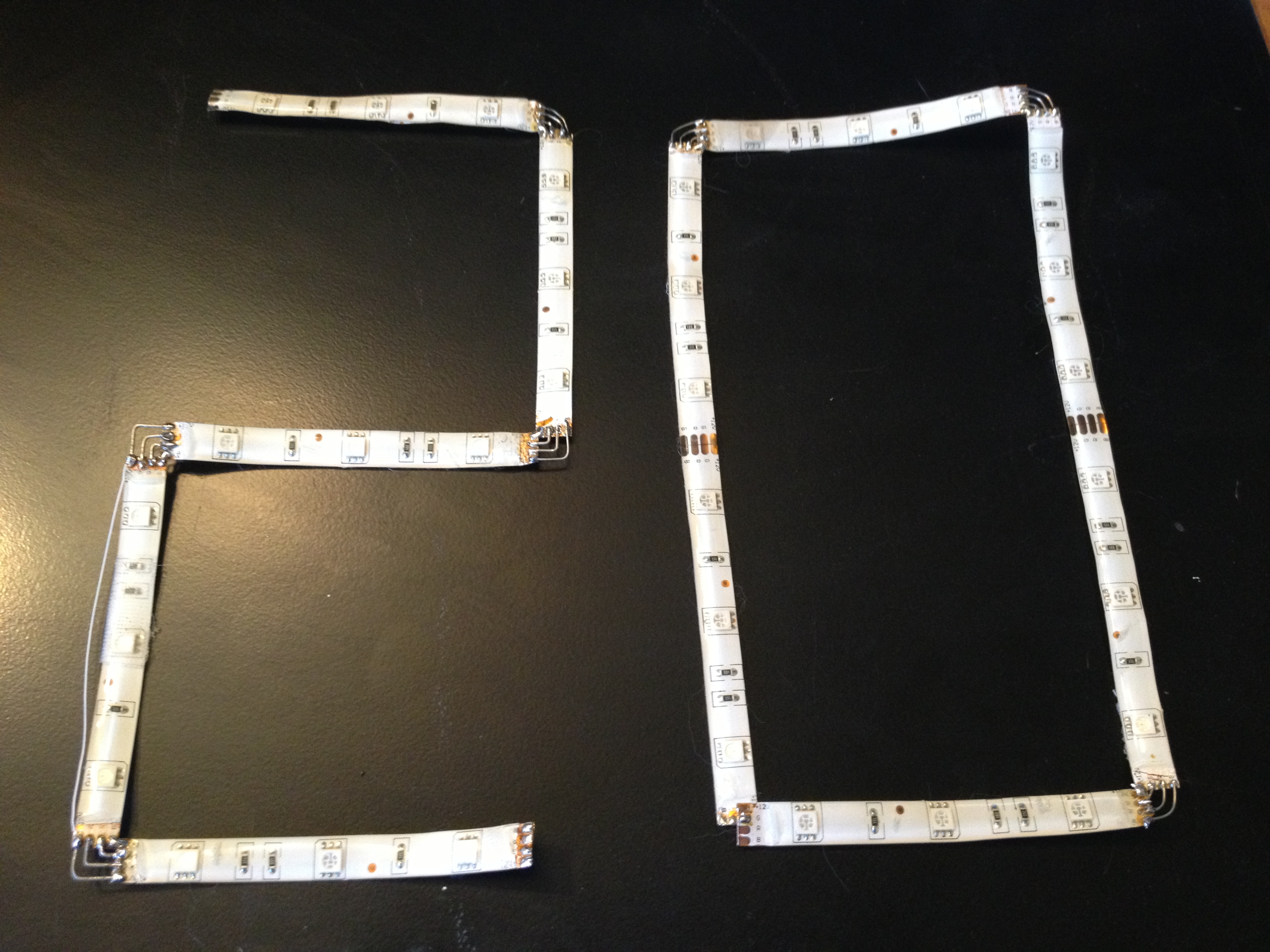
Do this for All of your strips until you have your final shape.
Connect Your Shapes
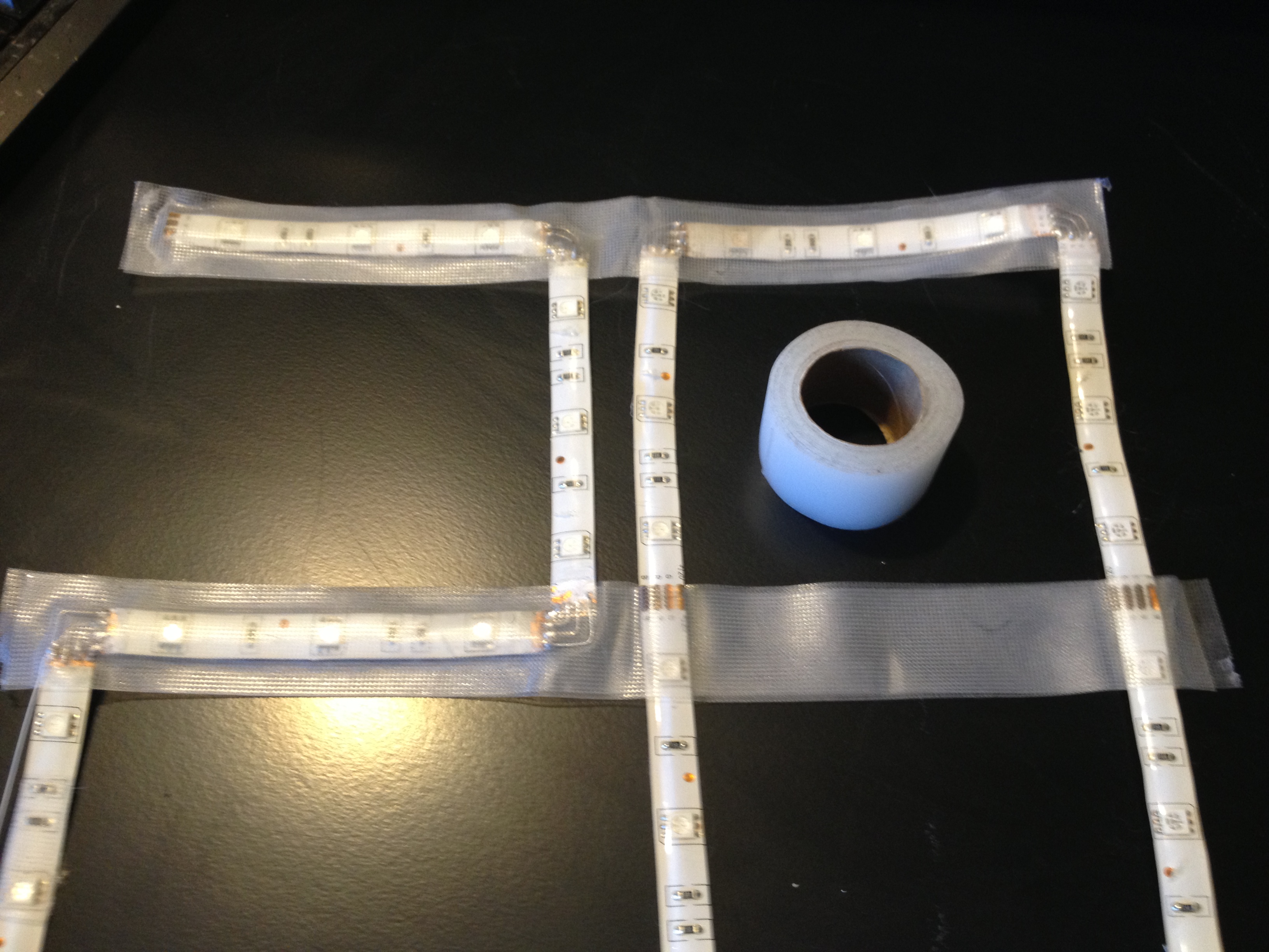
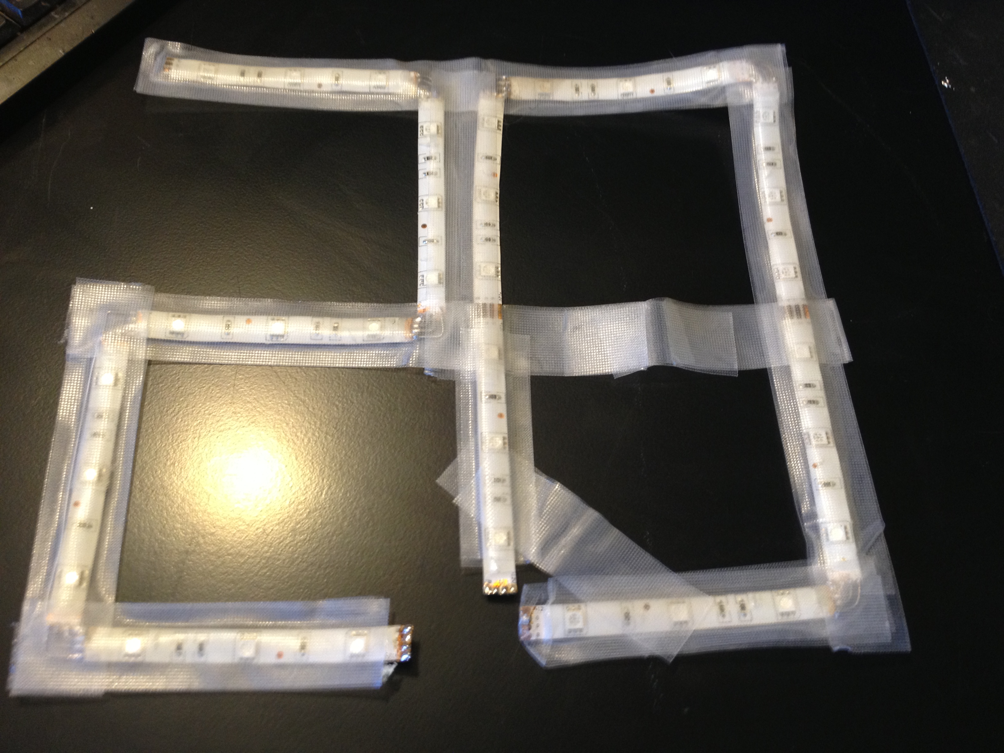
Solder Your Wires
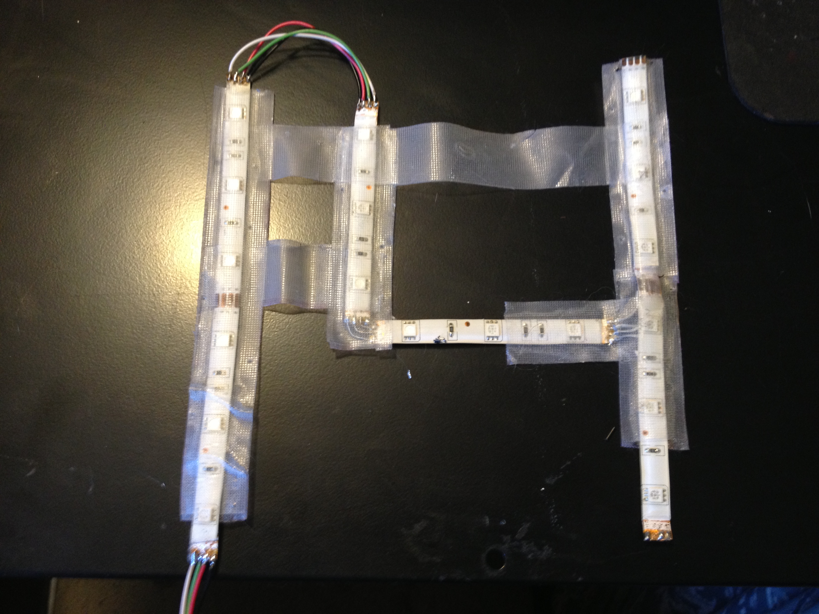
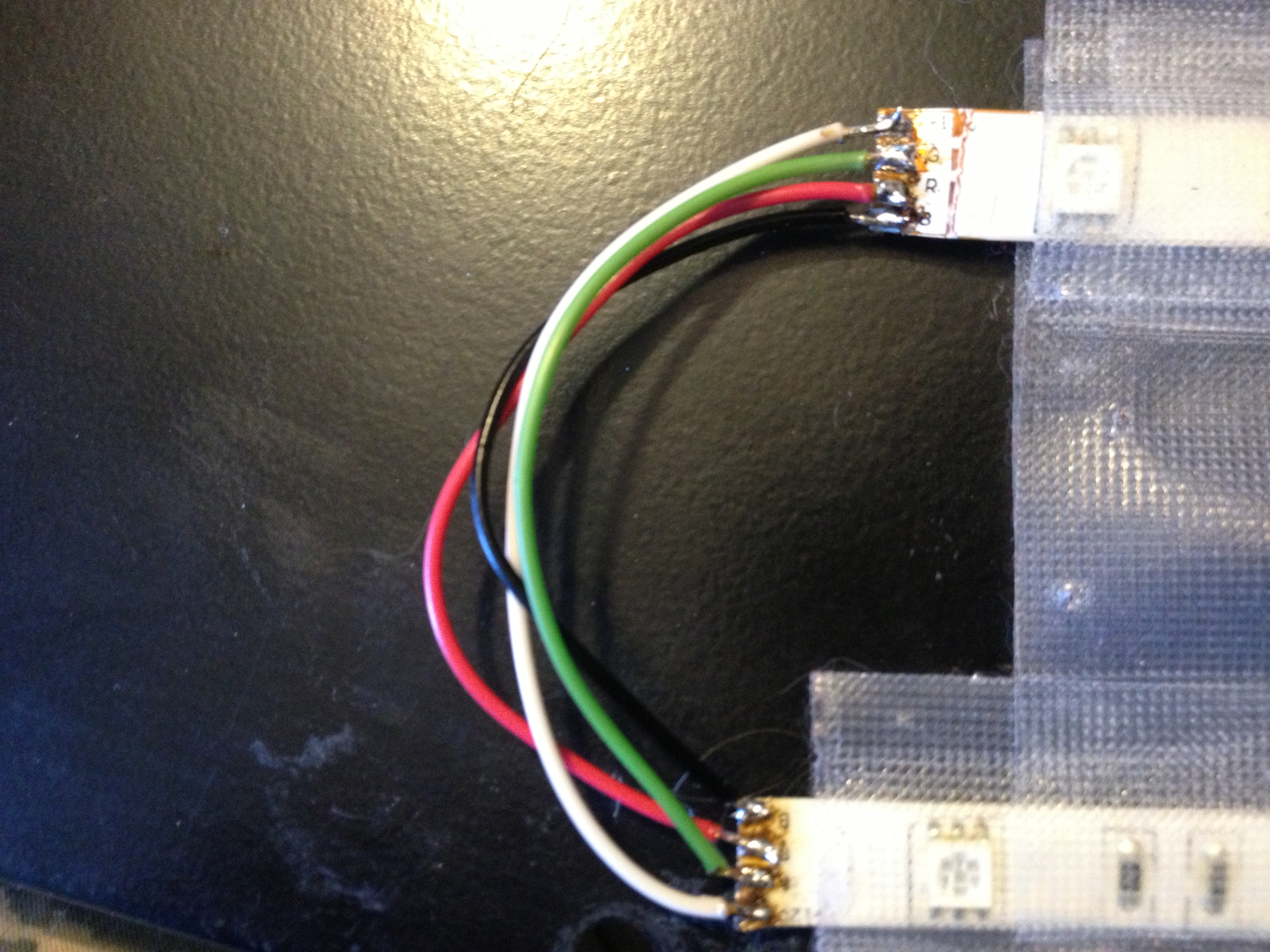
You will need 4 wires preferably different colors, I use black for blue, red for red, green for green, and white for common positive.
solder a jumper between each color for the two shapes (if you are doing more than one) then solder the same color wire to one end of each so that the two shapes are connected and you have four main wires to power it with.
*At this point I am going to switch to the number 14 because I have already gotten it this far*
Start the Controller
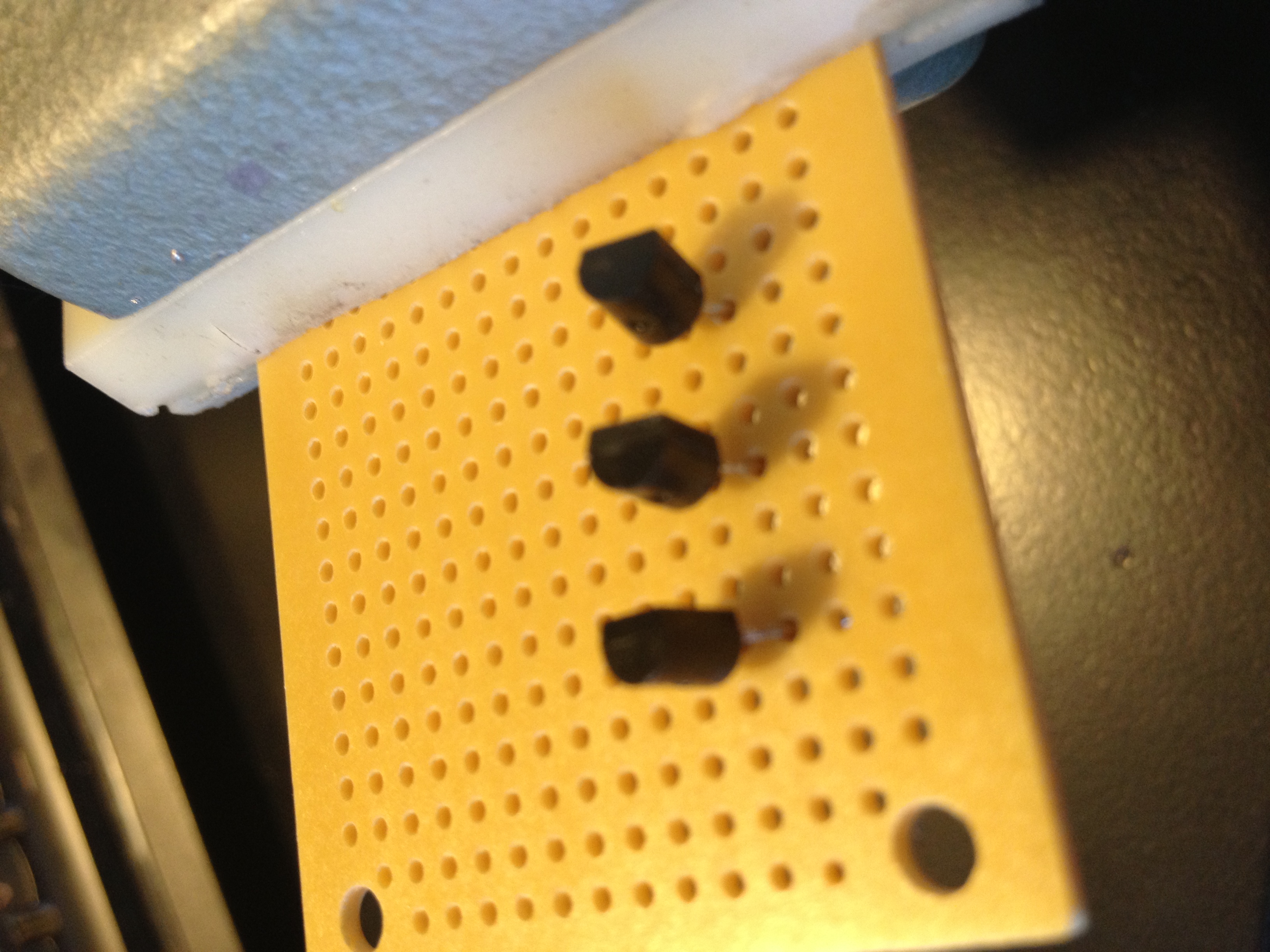
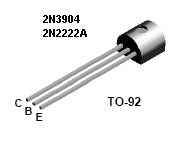
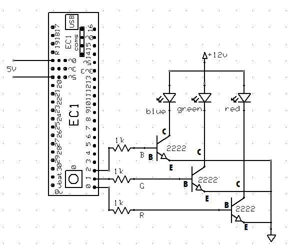
We will begin by placing the 3 2n2222 transistors in a line with 2 rows between each to make it easy for soldering, then solder and trim the leads.
*Above is the final schematic for the controller if you want to jump ahead*
Add Some More Parts
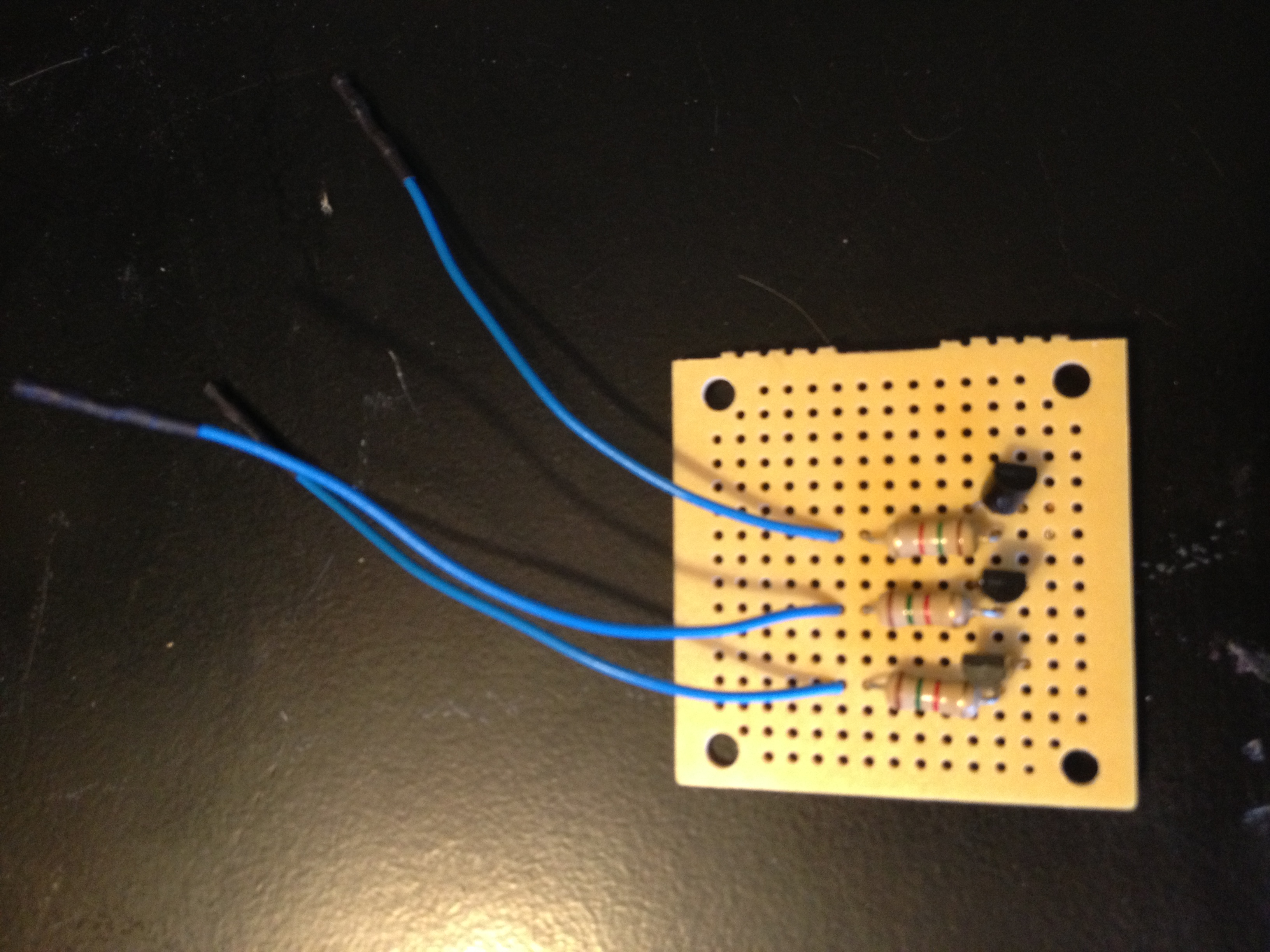
Add the Regulator
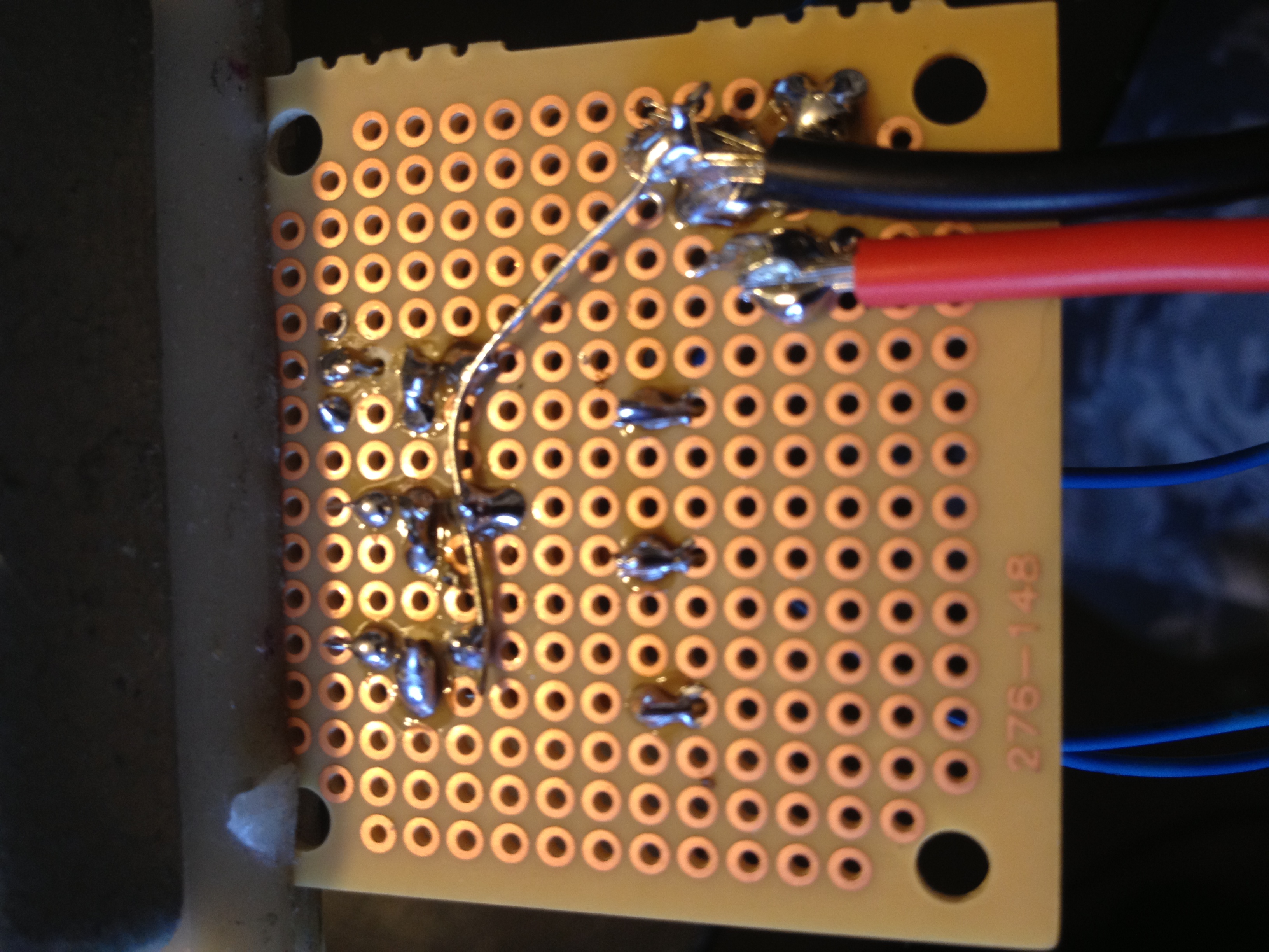
Connect the Leds
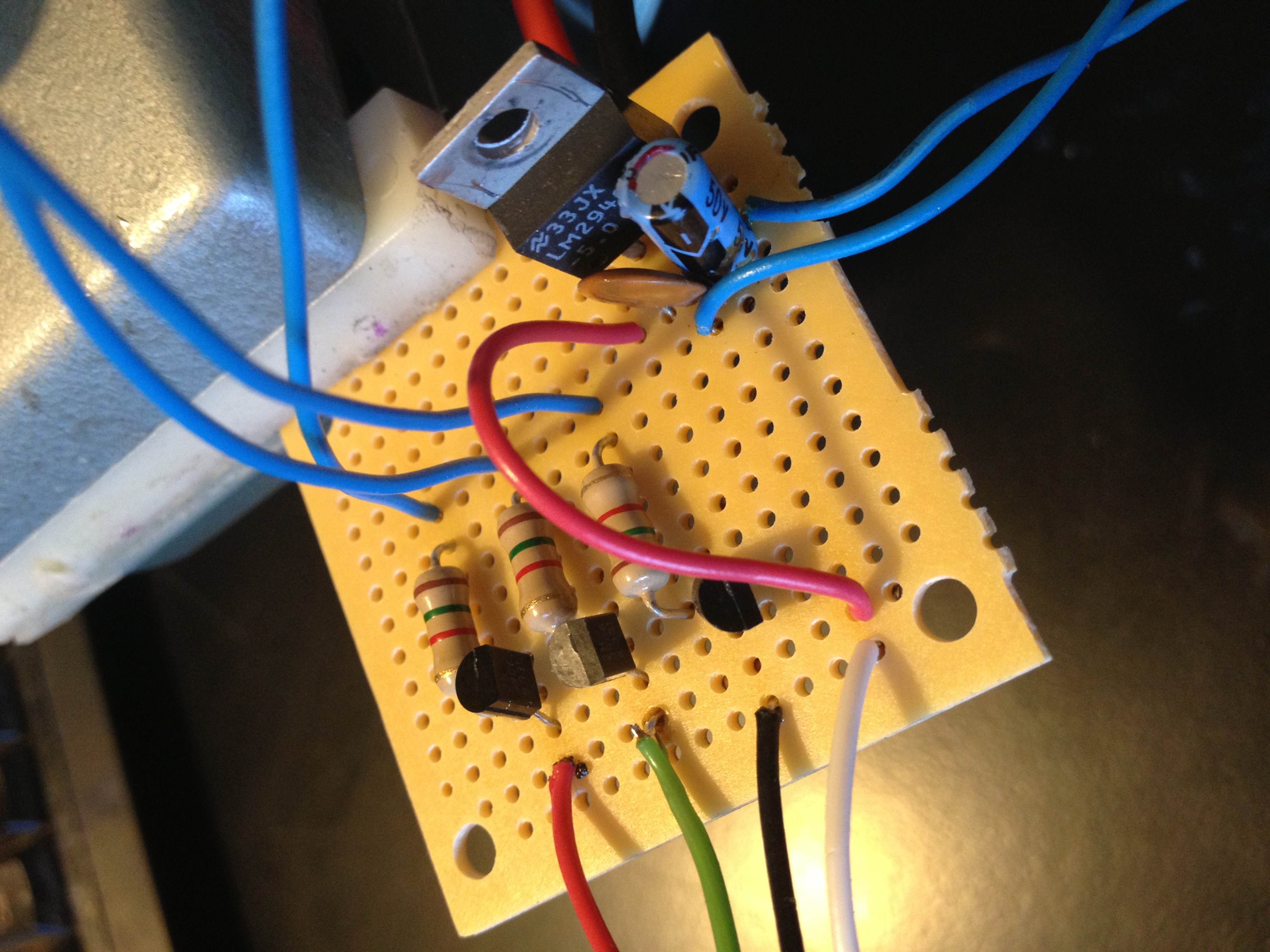
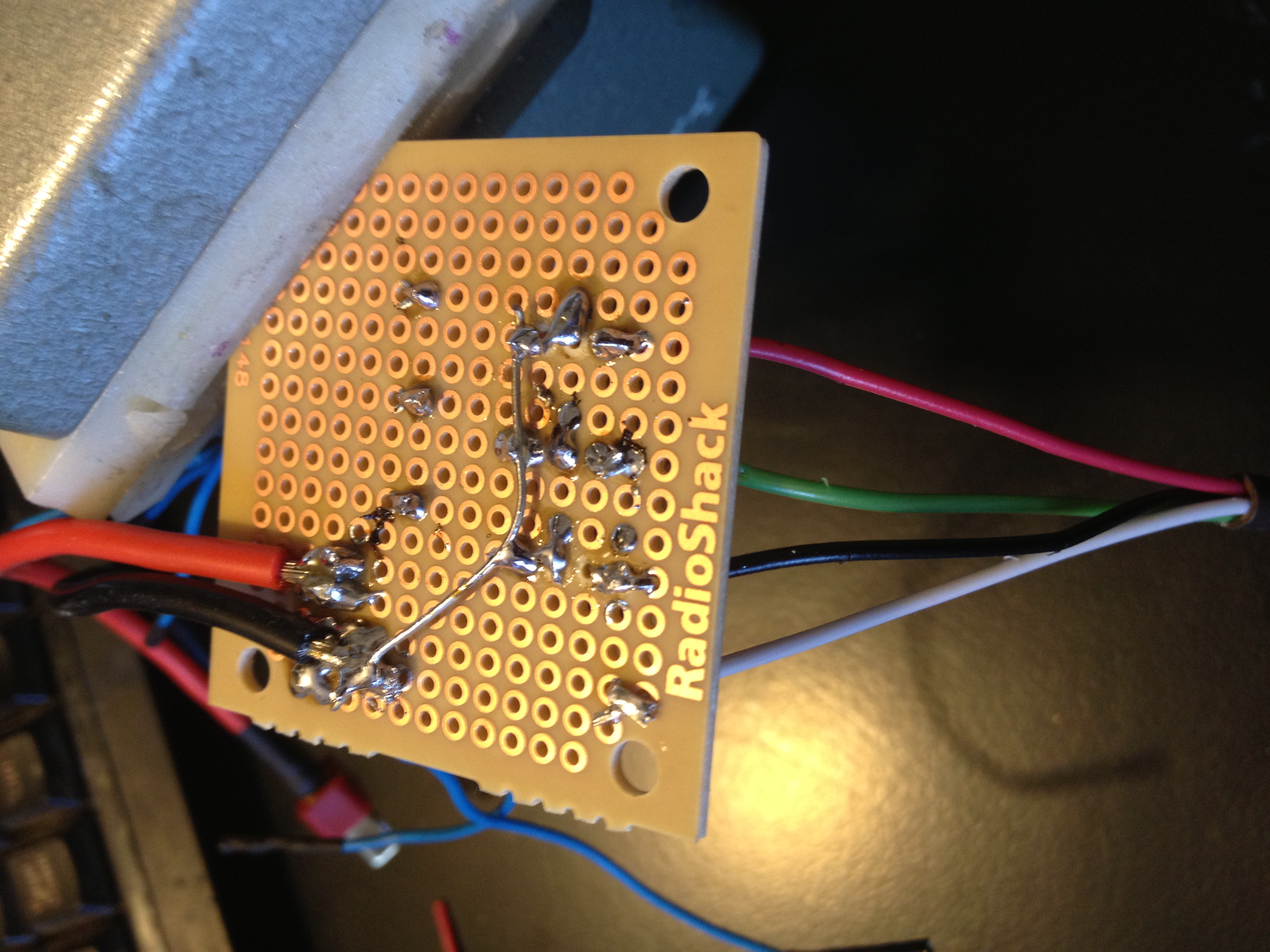
At this point all wiring is finished other than connecting the EC1 Splat board.
Program the EC1 and Connect the BT Module
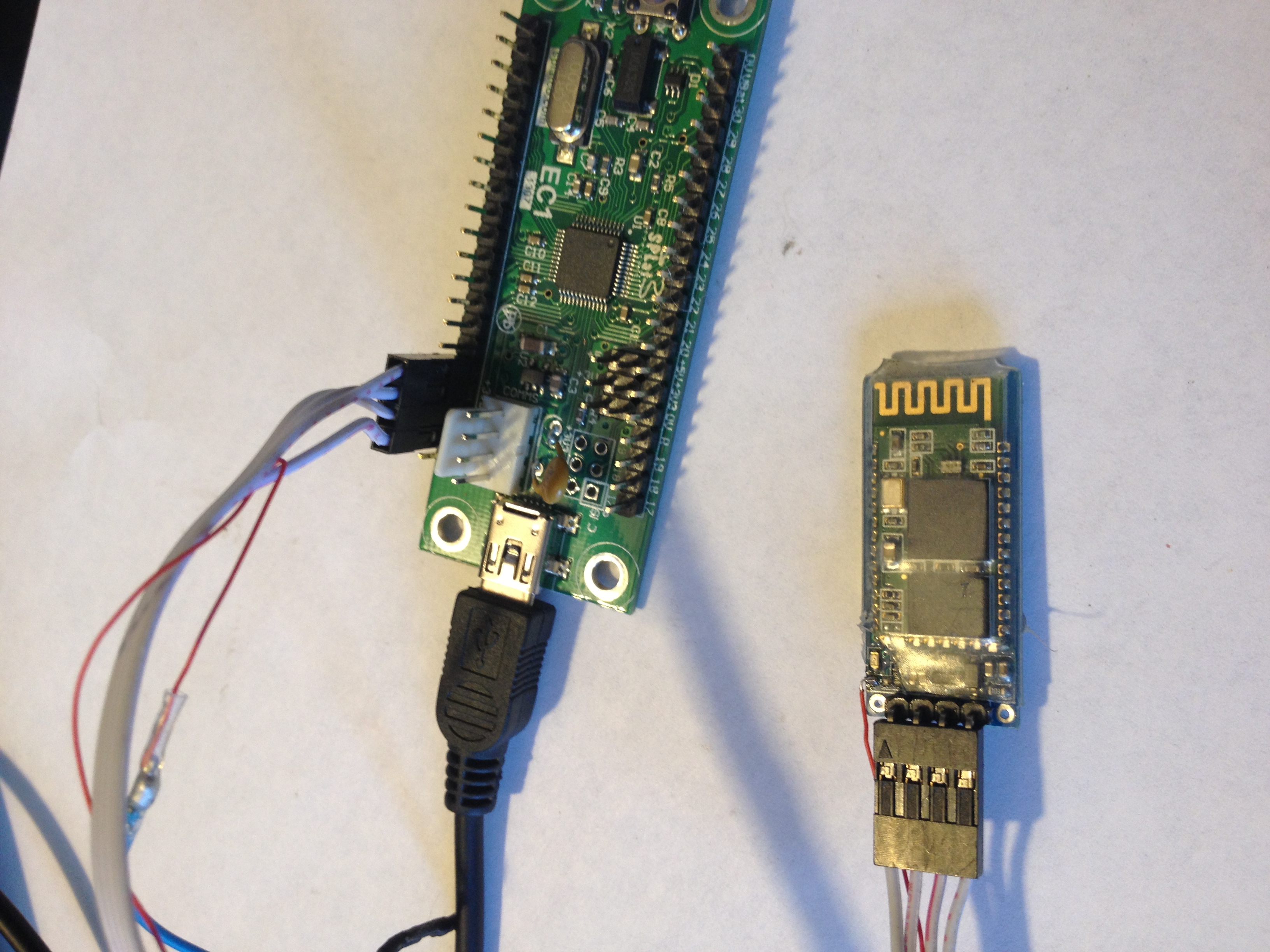
You can connect the BT board and plug the EC1 into your computer, you can find how to properly connect and pair your device to the BT board in the SPLat Easysteps "Connecting EC1 to a JY-MCU Bluetooth module". Now running SPLat/PC get the program from the Splat Easysteps "control an RGB led from your smartphone" and paste it into splat. once you have connected to your splat board you can now load the program onto the EC1 and unplug it.
Testing and Sewing
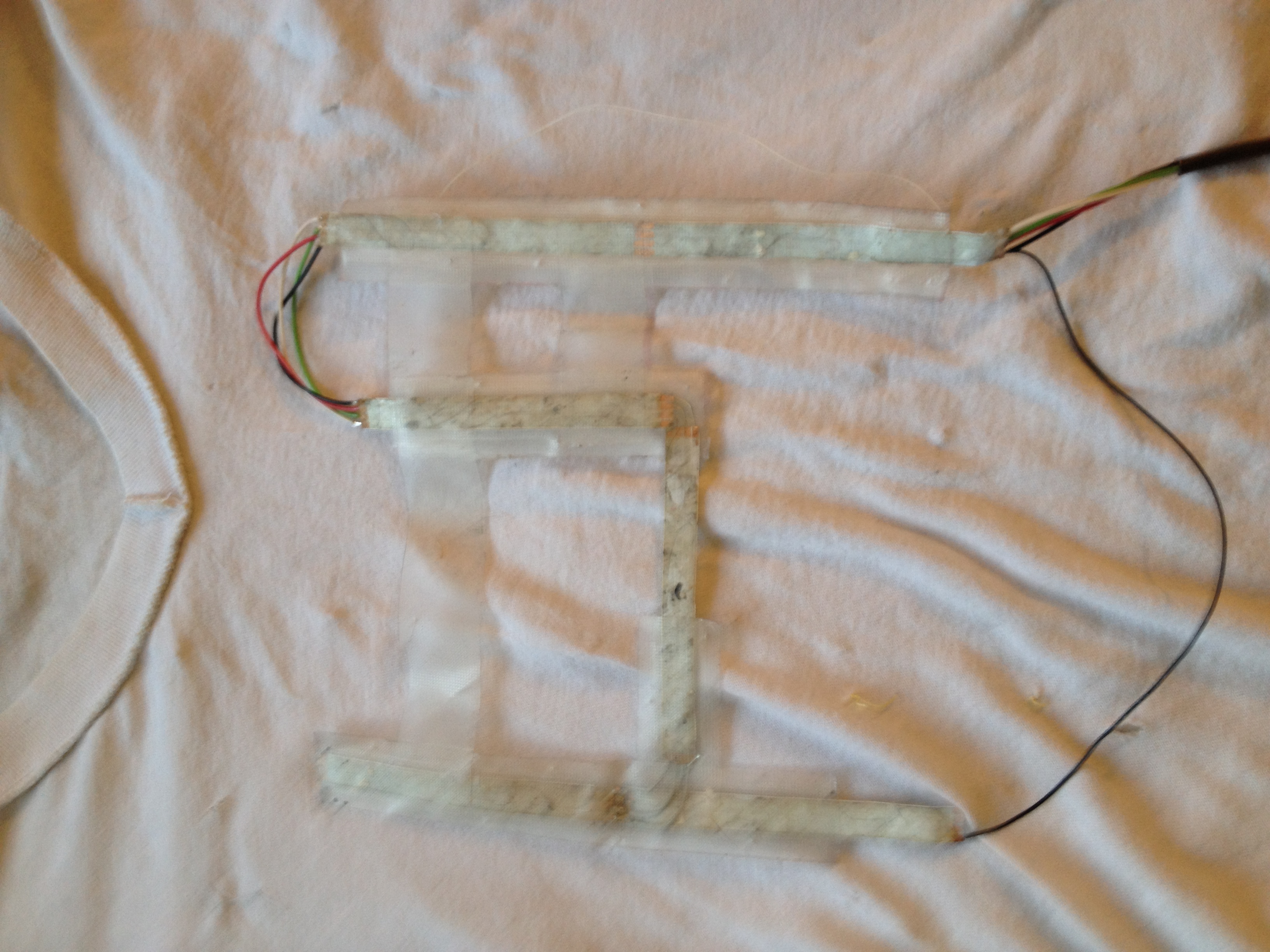
After you confirm that everything works you can now grab that white T-shirt, turn it inside out and lay it down flat with the front side on top.
Place your lights face down on the shirt and begin sewing the leds to the shirt by threading the needle through the tape and the shirt,
(make sure the lights are positioned where you want them)