Make Any Vintage Keyboard Work With a Modern PC
by alpinedelta in Circuits > Arduino
43555 Views, 79 Favorites, 0 Comments
Make Any Vintage Keyboard Work With a Modern PC
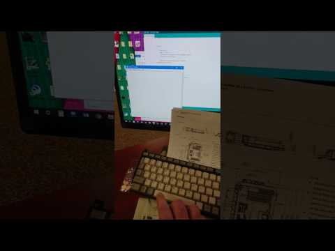
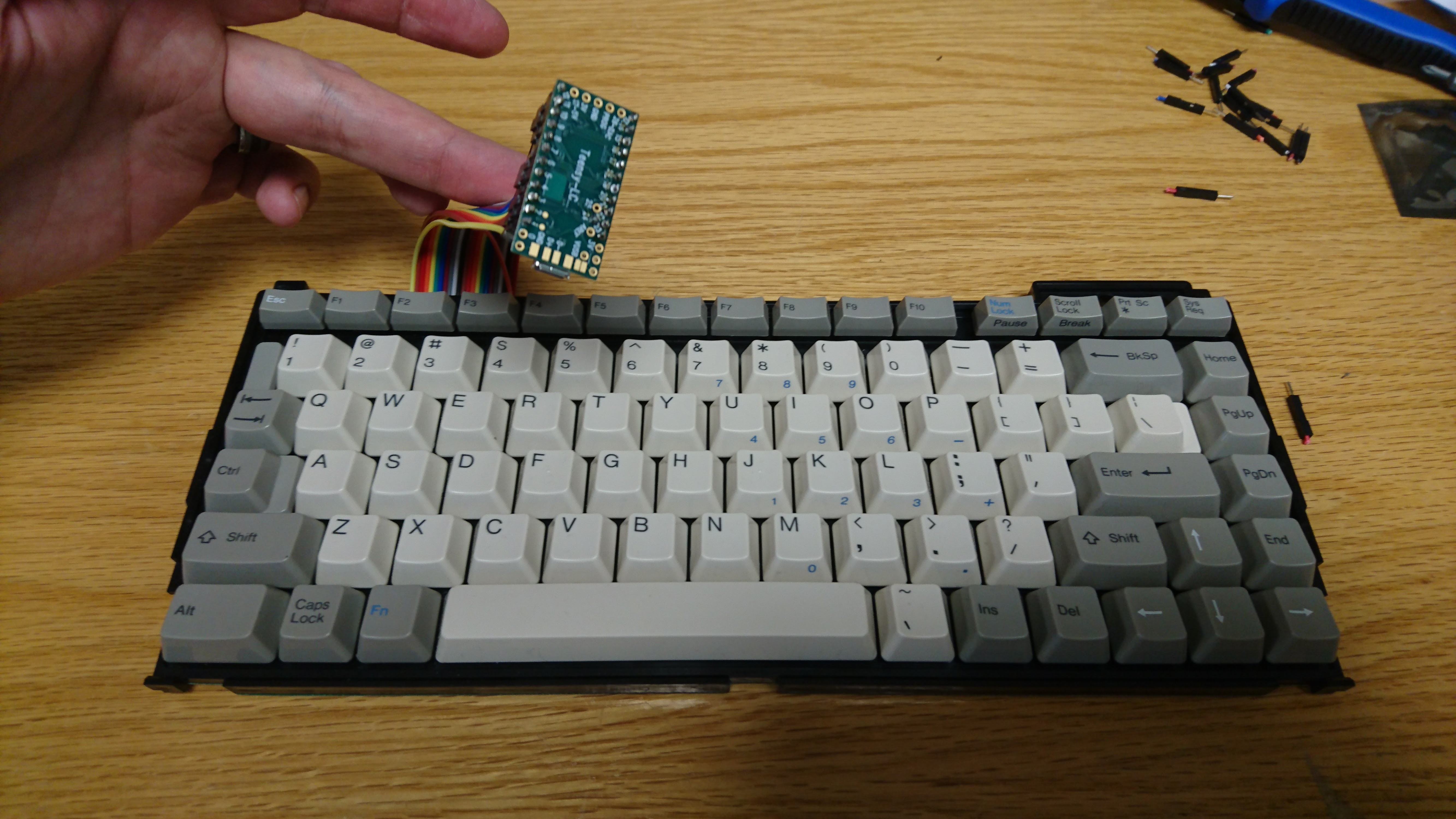
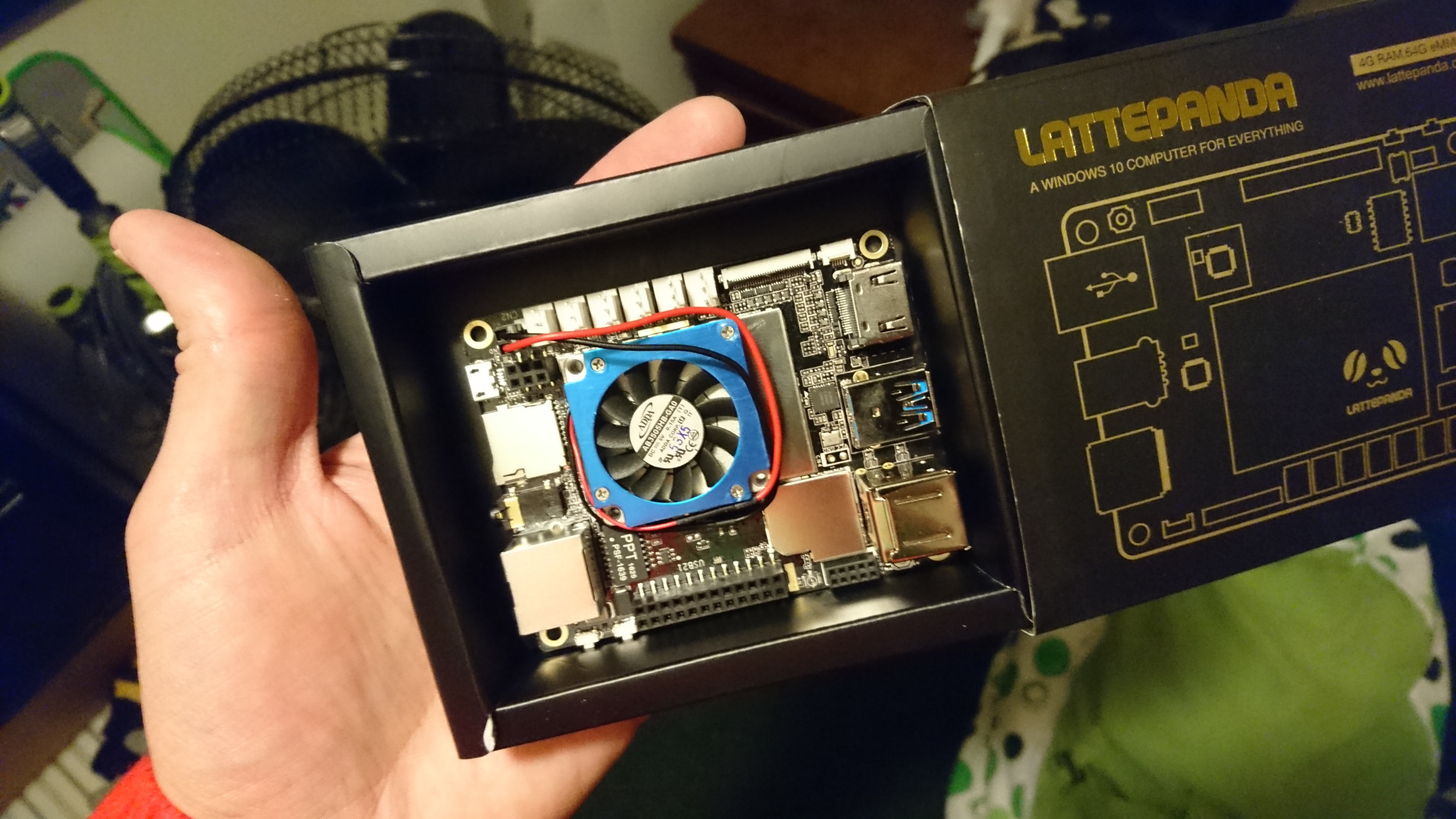
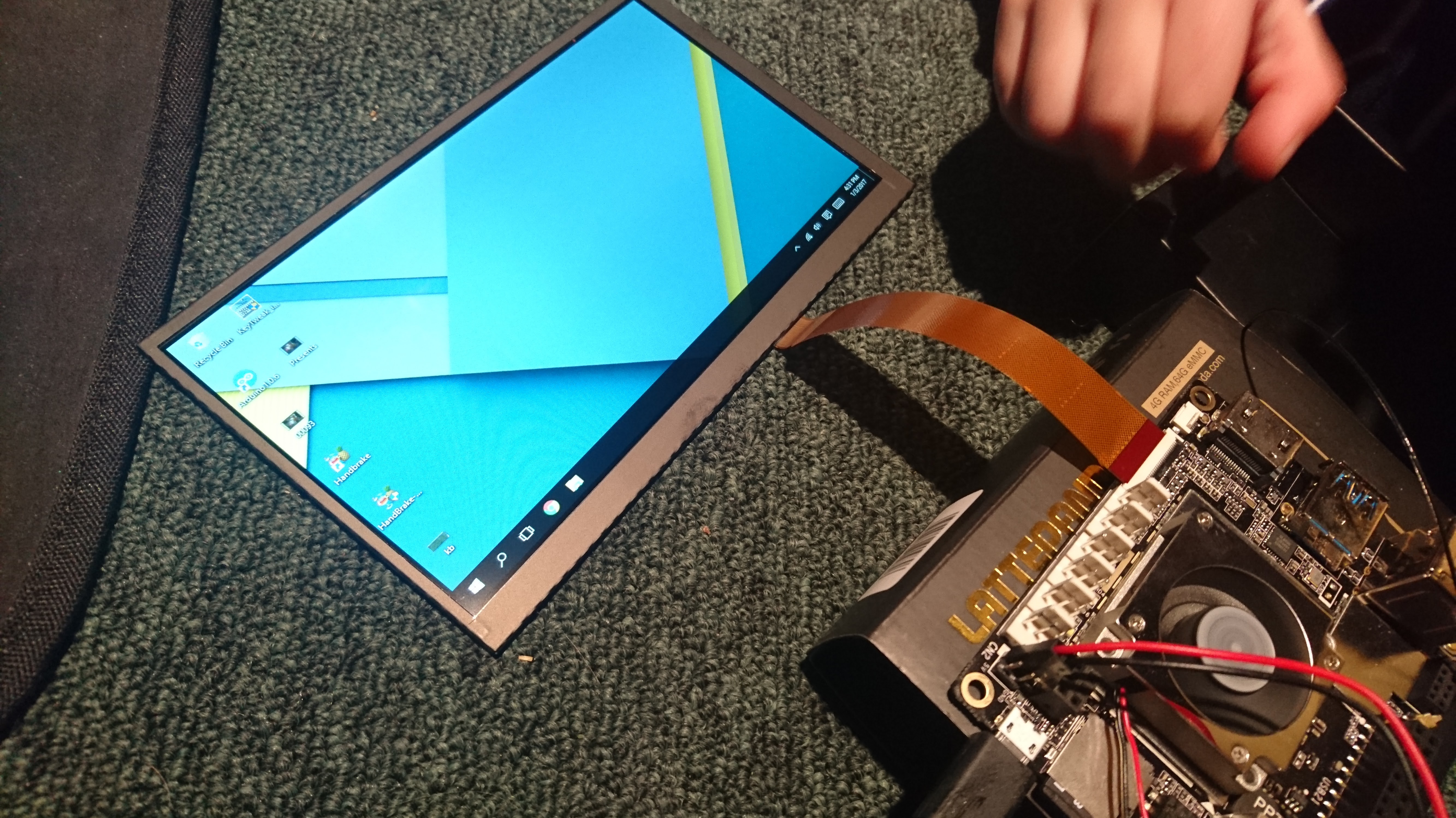
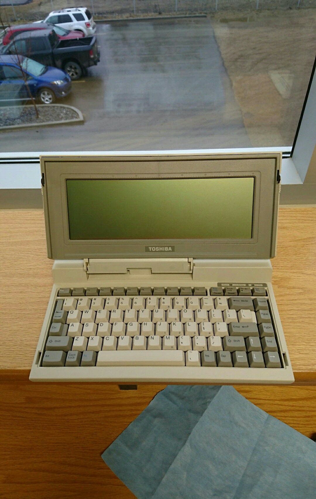
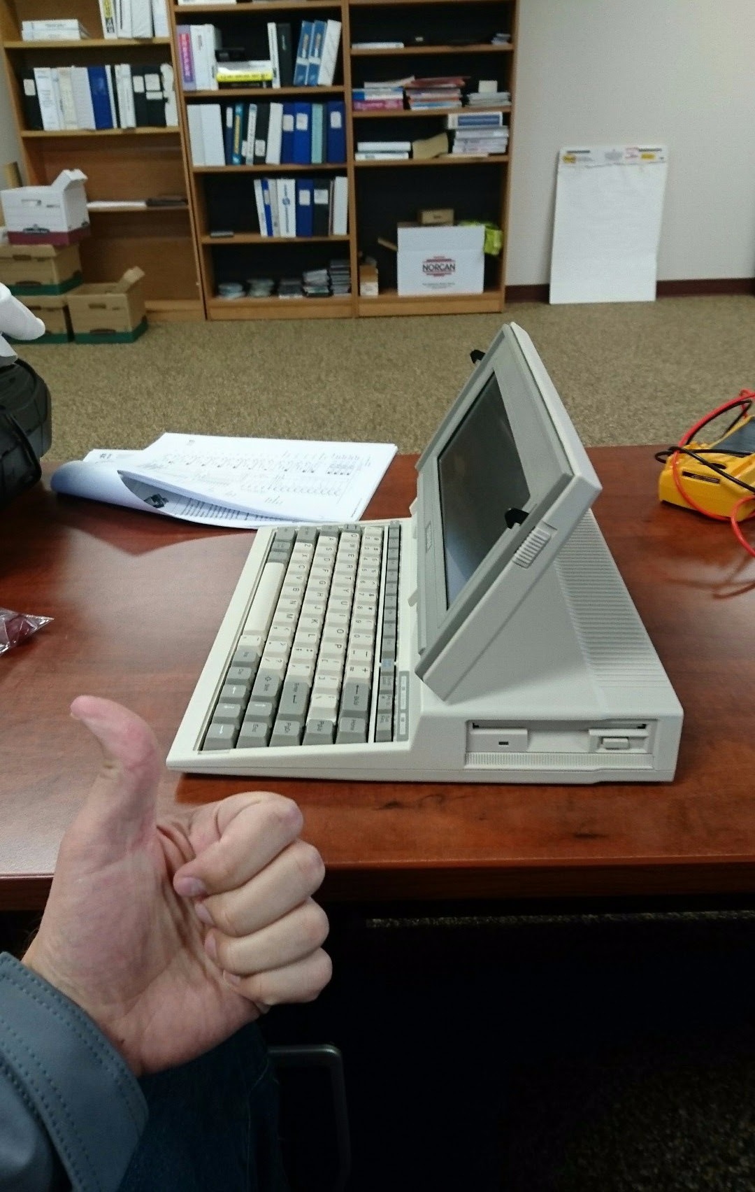
So this is part of a larger project to modernise a 1987 Toshiba T1000 laptop using the amazing and tiny LattePanda. For those of you that don't know, the LattePanda is a tiny x86 computer board that has a quad core Atom processor, 4Gb of Ram, and 64Gb of flash storage and also contains an Arduino. And when I say it's tiny, I mean palm of your hand sized! The Laptop project will be a whole other Instructable when it's done. For now this guide will show you how to make your old non standard keyboard work with USB. That means this same process can be applied to a Commodore 64 keyboard or whatever you like!
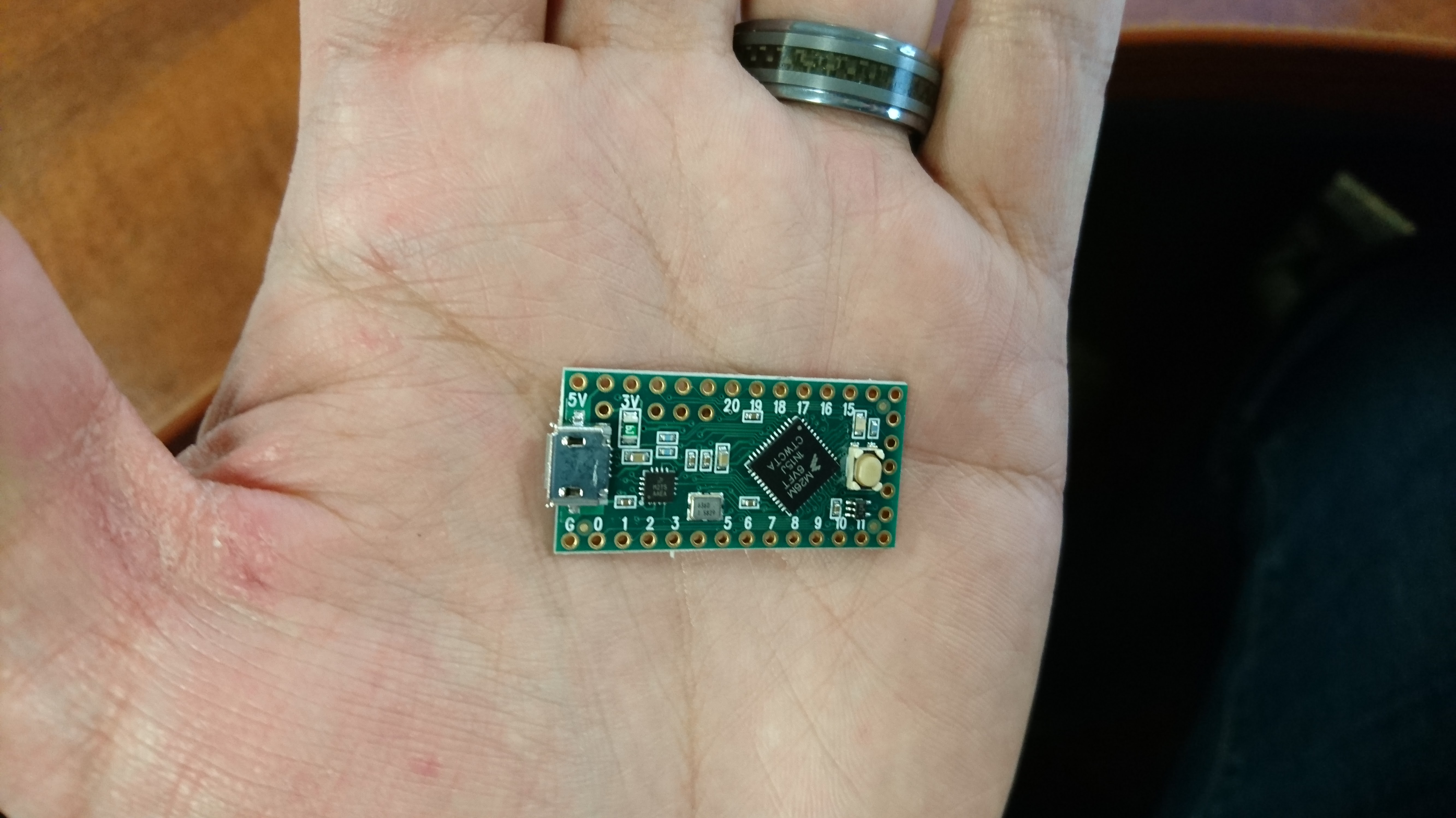
The largest obstacle in this project for me was interfacing the old original keyboard with the modern system via USB, and having Windows think it's a regular keyboard. I first thought I could buy a USB keyboard, rip out it's controller and somehow tie it into the old keyboard. I spent quite a bit of time on this, and to some extent it it did work. But I could never get all the keys to work. I thought it best to use and Arduino then, and modify a couple sketches to get it working. Although the LattePanda has an Arduino built right in, it is limited to 20 input pins and cannot be programmed to be seen as a keyboard by windows as much as I could tell. But then I got wise to the existence of the Teensy LC micorcontroller, and this changed everything. The Teensy is as the name suggests is tiny, and has more than enough I/O pins. It's also very cheap and light on power.
Materials:
-A keyboard of your choice disassembled
-Teensy LC or other Teensy
-Ribbon cable with solderable pins on the end (optional)
Get a Picture of Your Key Matrix, and Trace Those Lines Out
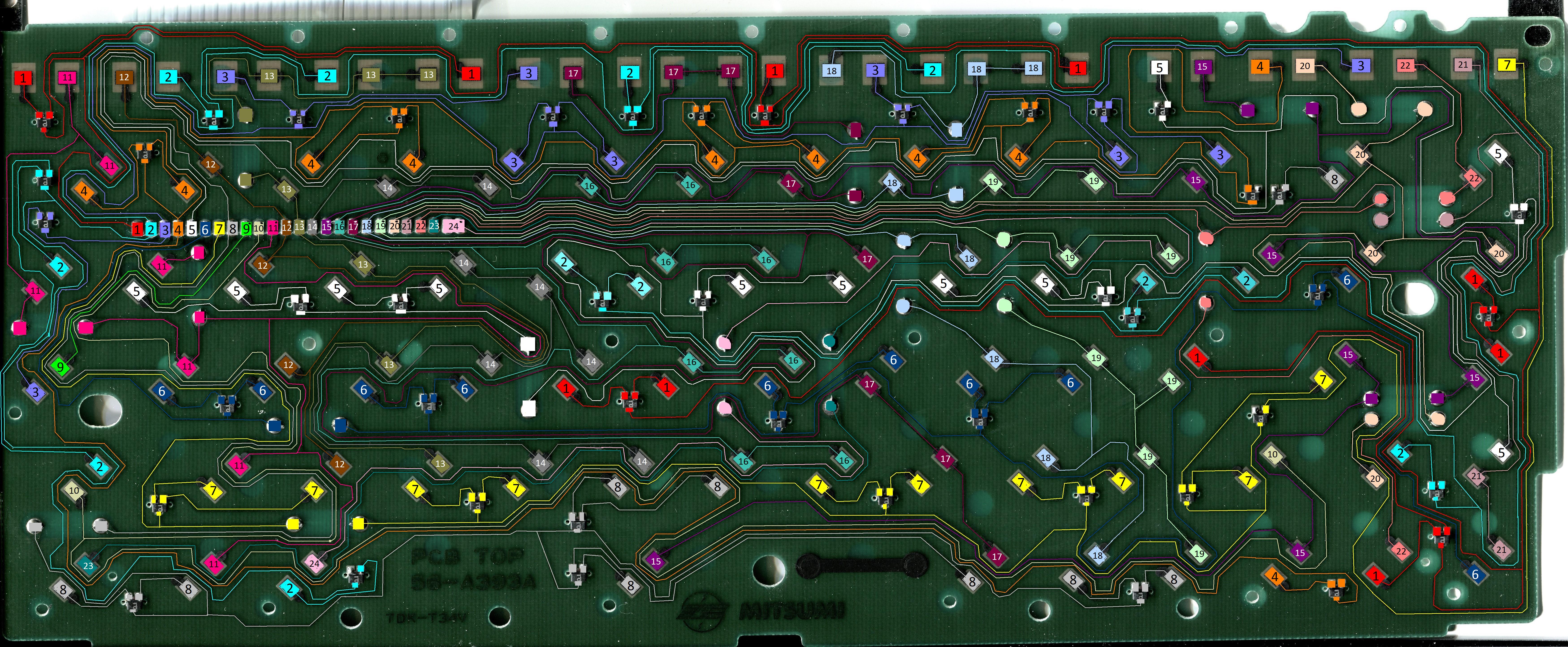
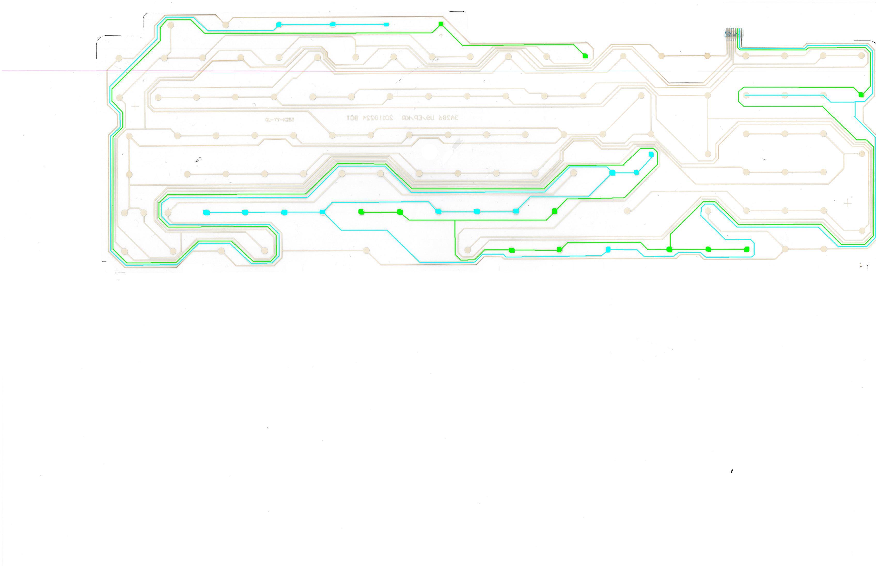
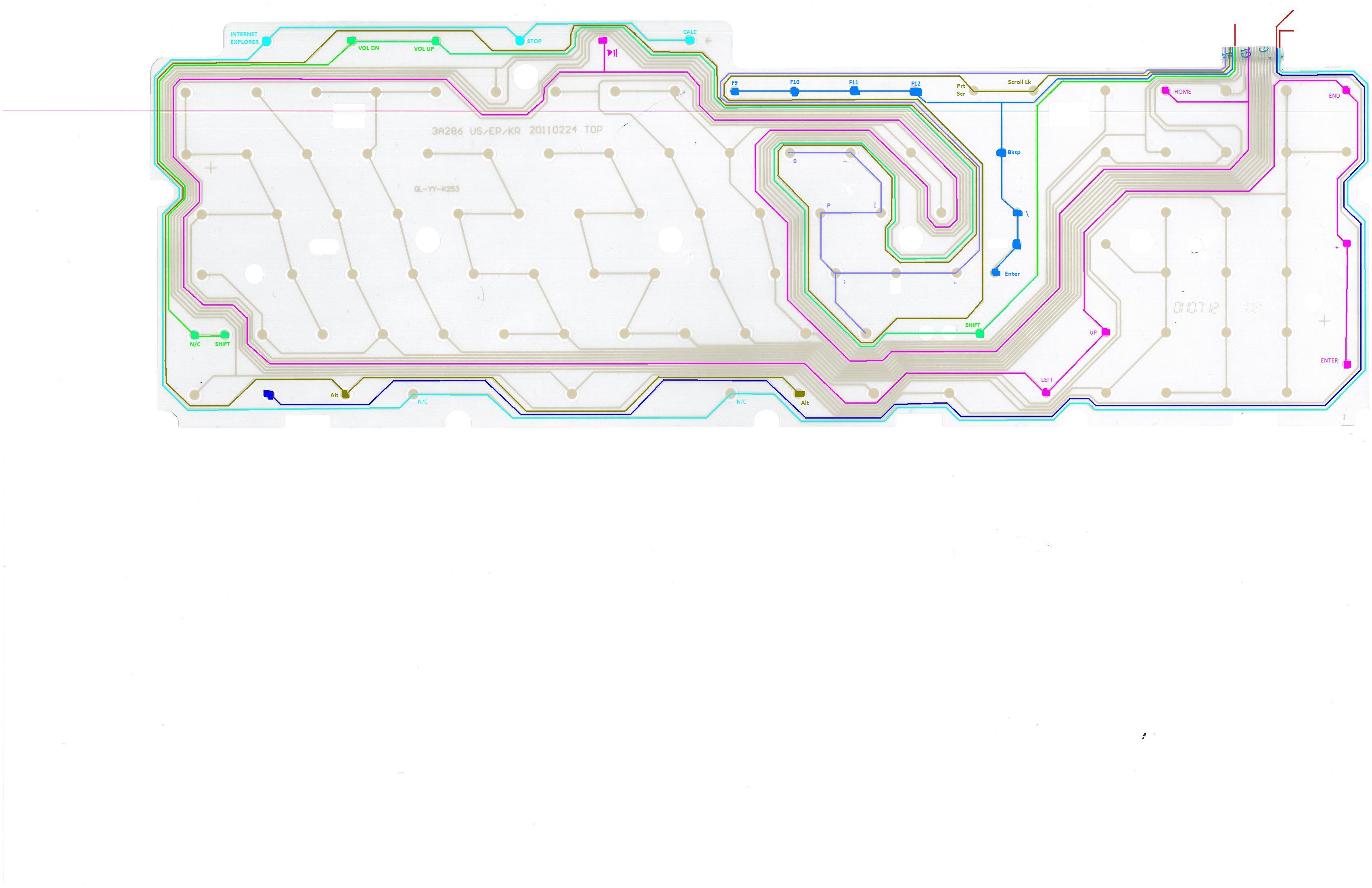
This is the most time consuming part. If you successfully trace out a whole PCB like this then you've got yourself some pretty high geek cred in my books. This board (it also may be a clear film with two layers) is called the key matrix. There are typically two sets of wires coming out of every key matrix. One set will be one side of every key, and the other set the other side of every key.
In my case I had 24 wires coming out. Numbers 1-8 were the first set, and 9-24 were the second. What I did to make things easy was put the board in my flatbed scanner so I could get a nice high resolution image of all the lines. You could use your camera as well. Now for every one of the contacts (wires connected to the board), trace the lines like I did using a different color for every line. I found it helpful to number each pad that connected with a key to the number of the contact it's connected to. In the case you are working with a keyboard that has the clear film, you will have two layers that you need to scan. Each layer is a set as described above. One will probably have 8 contacts coming out, while the other will be around 16. In the photos you can see I started tracing out the lines on a film style key matrix.
Create a Spreadsheet of Keys and Their Contacts
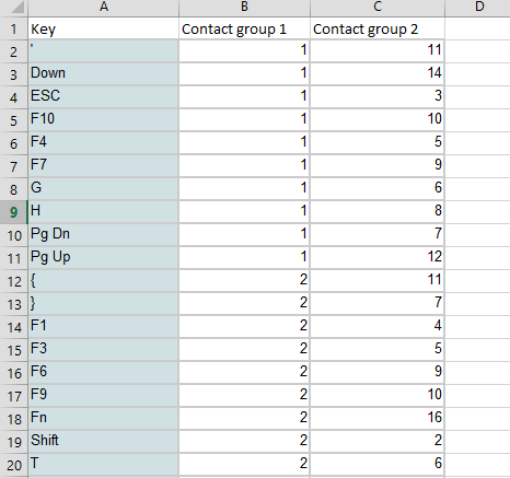
Now that you have a piece of keyboard art (I mean just look at all those pretty colours you picked!). You need to get the data into a spreadsheet. Each key will have two contacts assigned to it (one from every group). You can use my attached spreadsheet as a template. Your keyboard will probably have more or less keys, so modify as need be.
Downloads
Wire Up Your Key Matrix to the Teensy
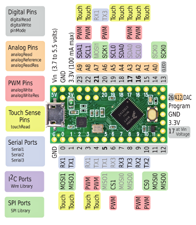
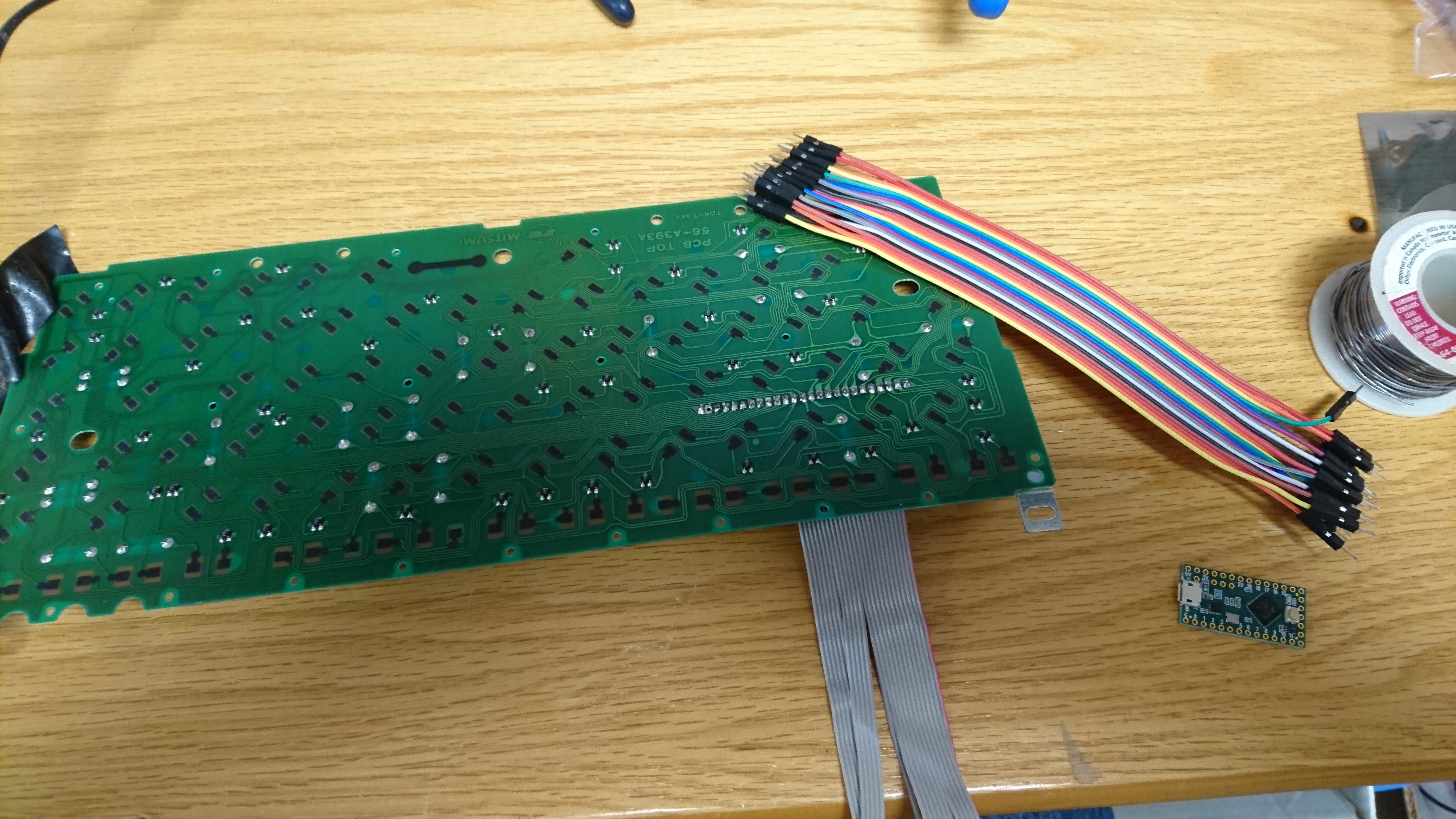
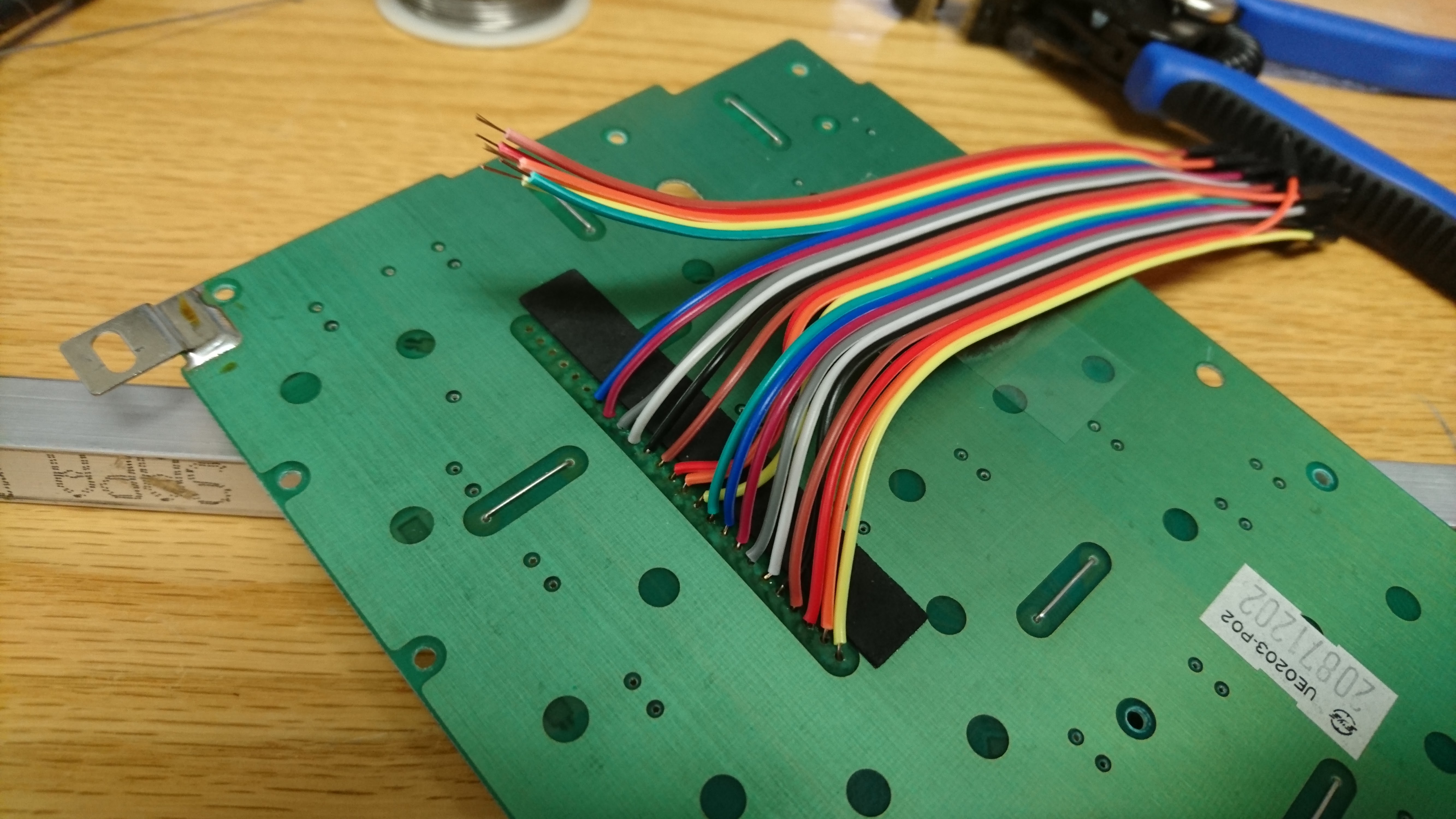
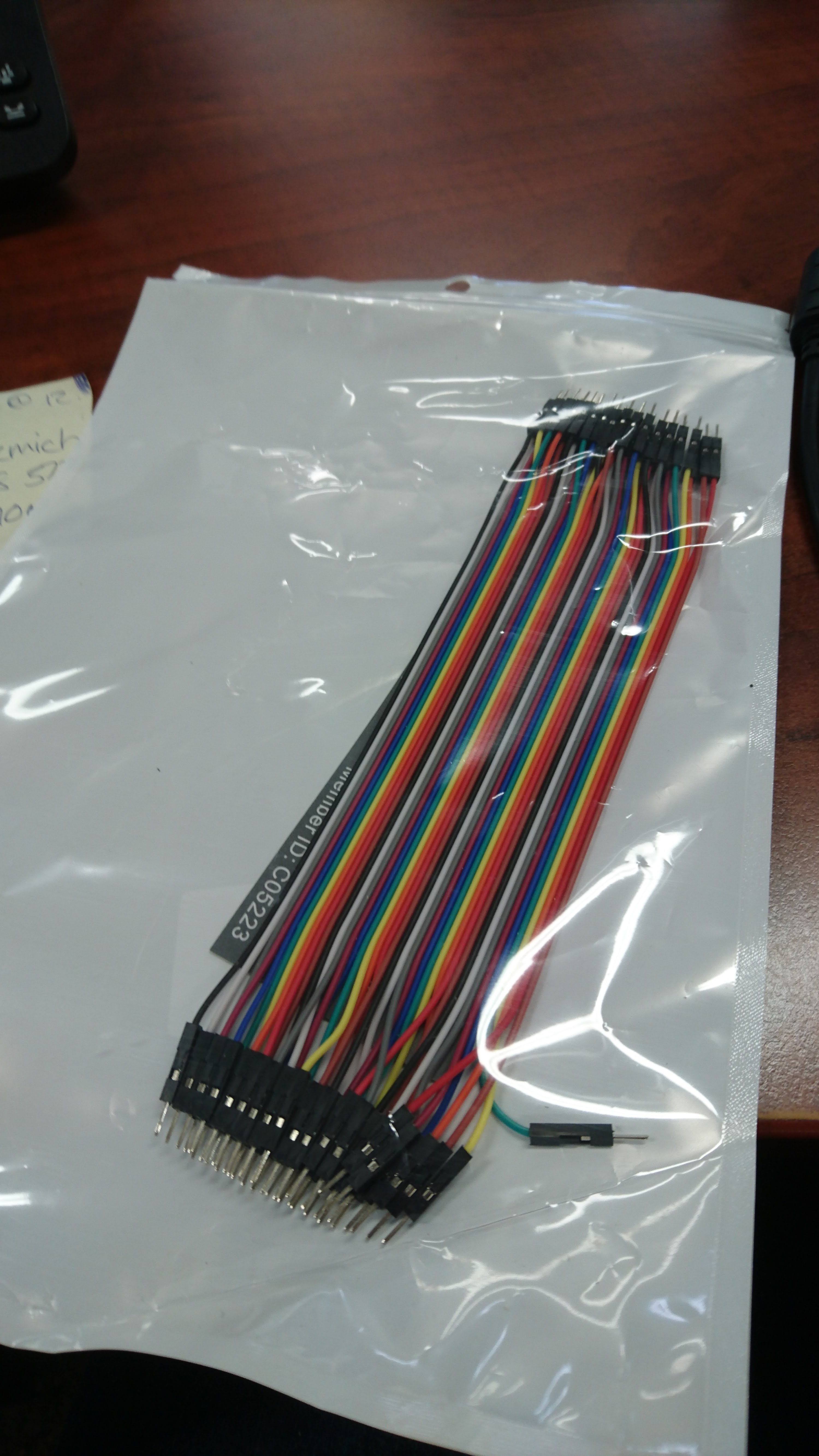
I hopped on amazon and got this fancy ribbon cable with pins on the ends for about $8 CAD. You can also just use the wires that were there to begin with, but the soldering on the teensy might be a bit more tricky.
To make it easy I used the same pin number on my key matrix as the one on the Teensy for all 24 wires. Ex. Key matrix=1 -> Teensy=1, Key matrix=2 -> Teensy=2, and so on. The Teensy LC I bought came with no pins, rather it had holes that you could solder into. This worked very nice in combination with the ribbon cable I ordered.
Setting Up Teensyduino and Modifying the Sketch
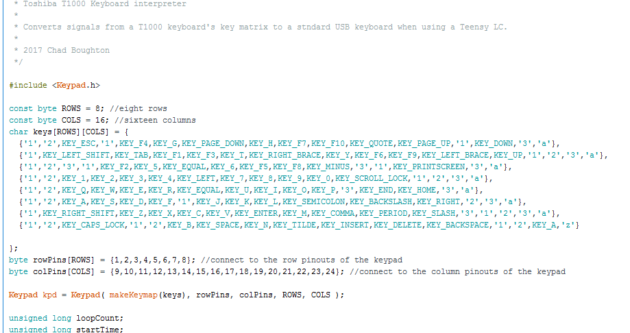
Teensyduino is an addon for the Arduino development enviroment. As of writing this, it only supports up to Arduino 1.8.1. If you have a newer version, you may need to uninstall and install 1.8.1 for it to work. Here is a guide on getting it installed: https://www.pjrc.com/teensy/td_download.html
This page was a huge resource when doing this project: https://www.pjrc.com/teensy/td_keyboard.html Once it's installed, you will be able to open Arduino and now select your Teensy as a board. You also have to go to Tools -> USB Type: and select "Keyboard". Download and open the sketch on this page with these settings. You will need to do two simple things to get up and running:
-Modify the keys Array (shown in the picture) to fit your spreadsheet from the previous step
-Modify the Rows and Cols to use the pins you've selected on your teensy. One set of wires will be the rows, and the other is the columns.
Before you can download to your Teensy, you need to press it's reset button. Once you do, quickly download your sketch.