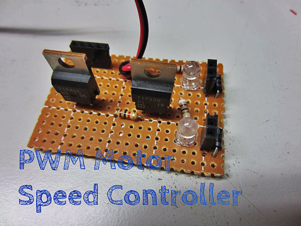
Make a PWM Motor Speed Controller
by DylanD581 in Circuits > Soldering
58403 Views, 368 Favorites, 0 Comments
Make a PWM Motor Speed Controller
Microcontrollers such as Arduinos are a great way to control your custom electronics projects. Unfortunately the digital pins have a max output of 40mA, and this isn’t enough to power most motors. This is where a motor controller shield can come in handy. But these are expensive to buy, and only let you control a few motors, especially if you are embedding them in a project.
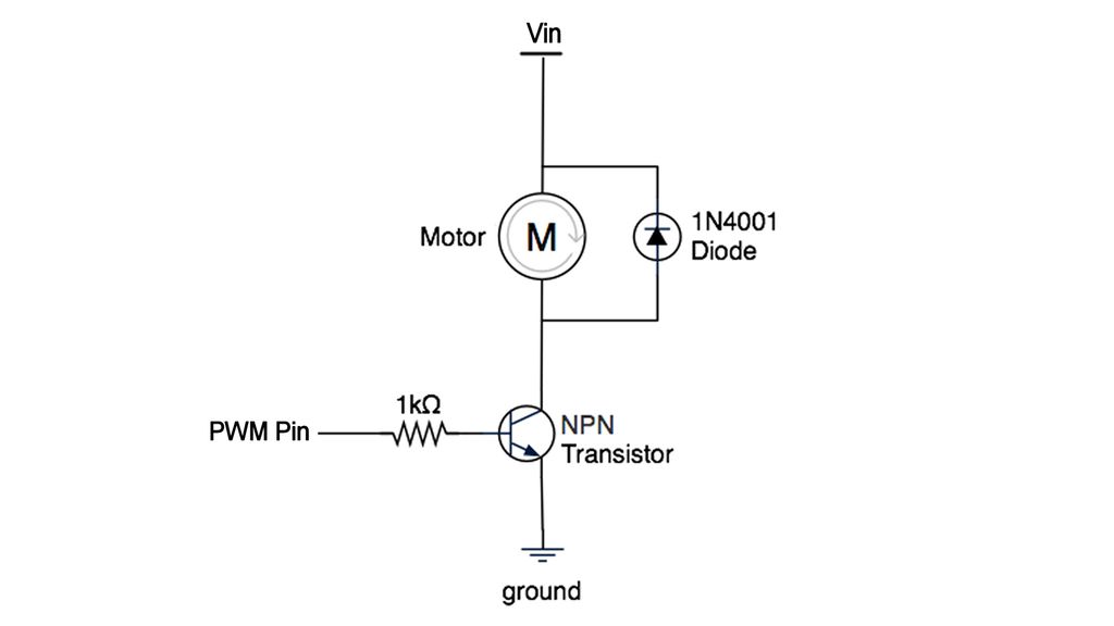
The simplest kind of speed controller uses a Pulse Width Modulation signal to set the speed of the motor. This signal can be generated by any of the Pulse Width Modulation pins on an Arduino. So we need to use an external power source (such as a battery pack) and a transistor switching circuit. This is similar to the transistor circuit on a relay shield, but we made a few changes. I included an LED for a visual indication on the output.
In this project, I am going to show you how you can make your own simple motor controller.
This is a remix of Jason Poel Smith's "How to Make Custom Shields for Your Microcontrollers" Instructable, and I remixed the Motor Driver Shield. Please vote for it in the Remix 2.0 Contest!
Tools and Materials
Here are the materials and tools that you will need for this project.
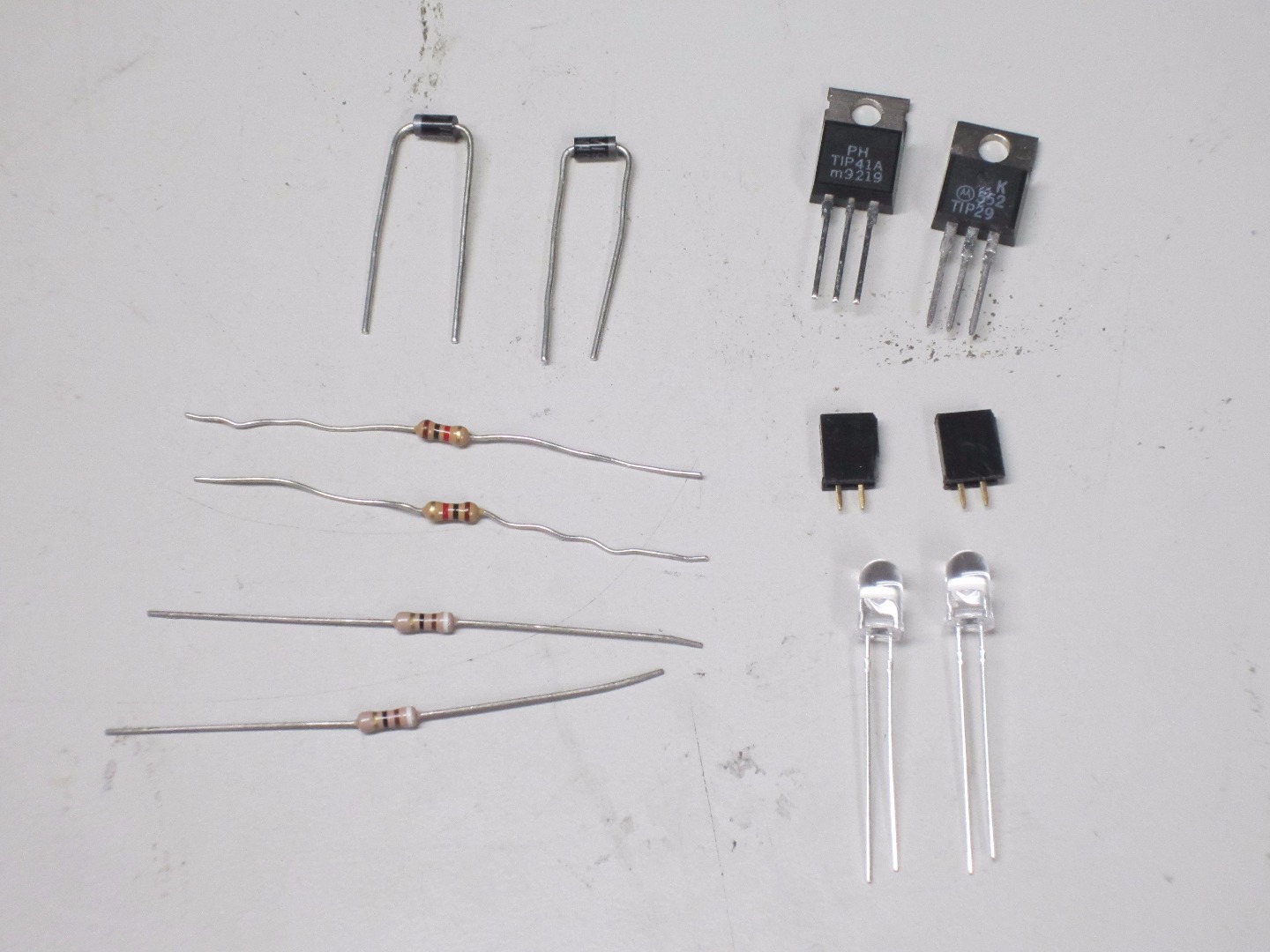
Materials:
2x NPN Power Transistor (such as tip31a)
2x IN4001 Diode
2x 1K Ω Resistor
2x 100 Ω Resistor
2x LED in your choice of color
2x 2 x 1 Female Headers
1x 1 x 4 Female Header
1x Battery Connector
1x 30 Gauge Solid-core Wire
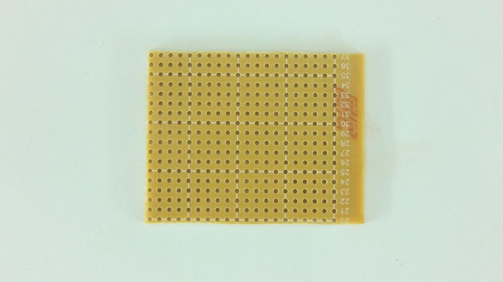
1x Perfboard
There are two of almost everything because we are making two motor speed controllers on one PCB. You can easily make only one circuit by cutting the double materials in half and using the schematic.
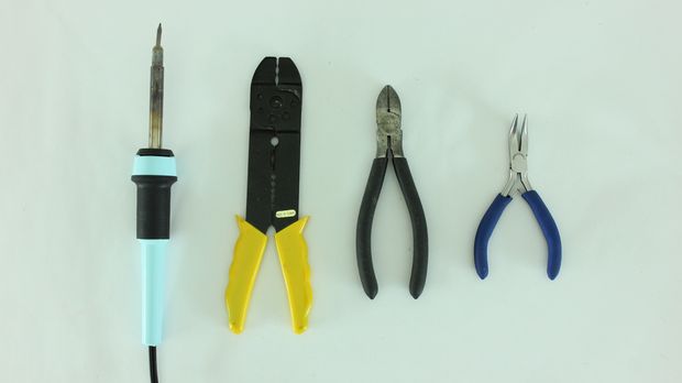
Tools:
Soldering Iron and Solder
Wire Cutters
Wire Strippers
Needle Nose Pliers
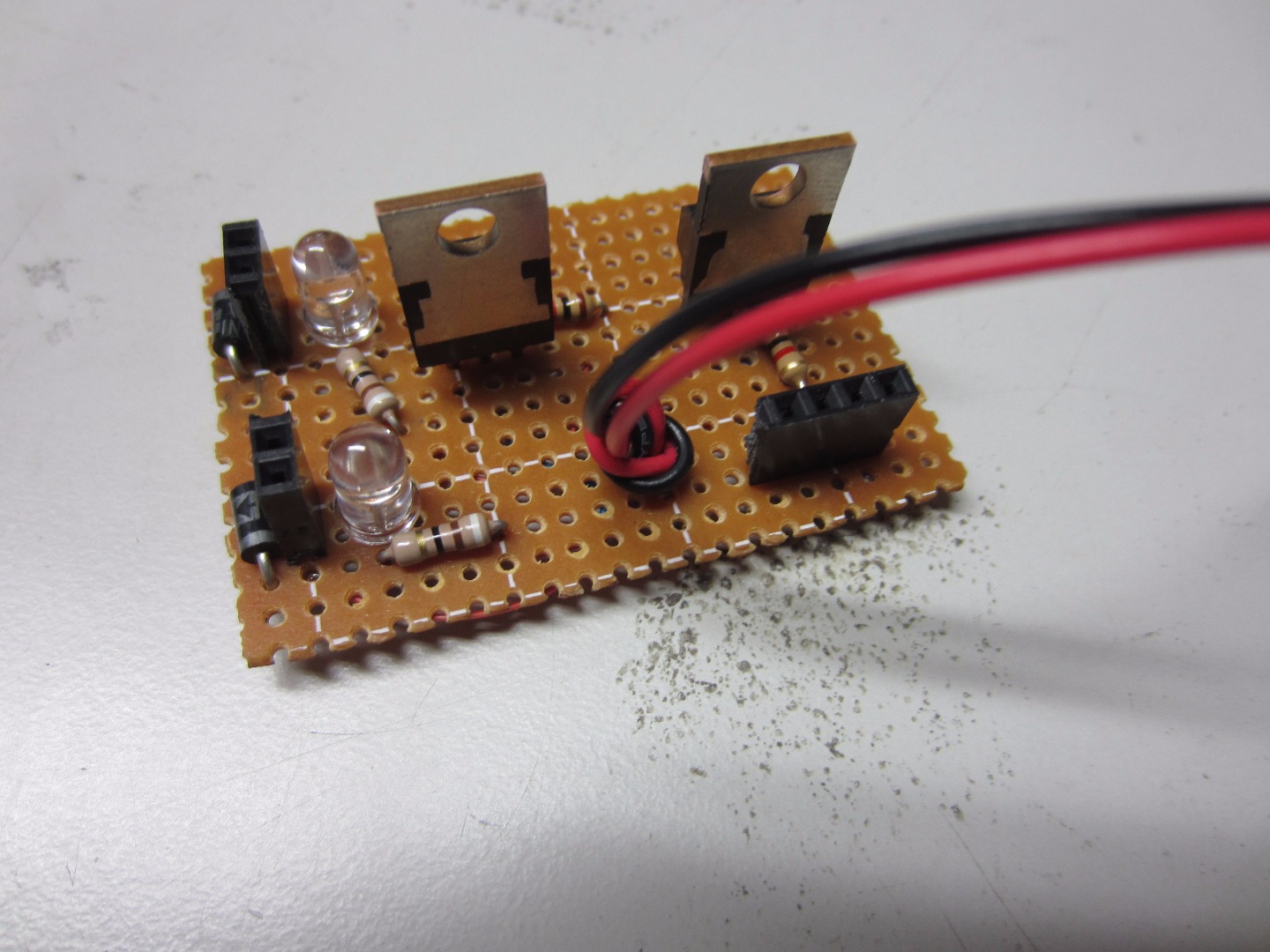
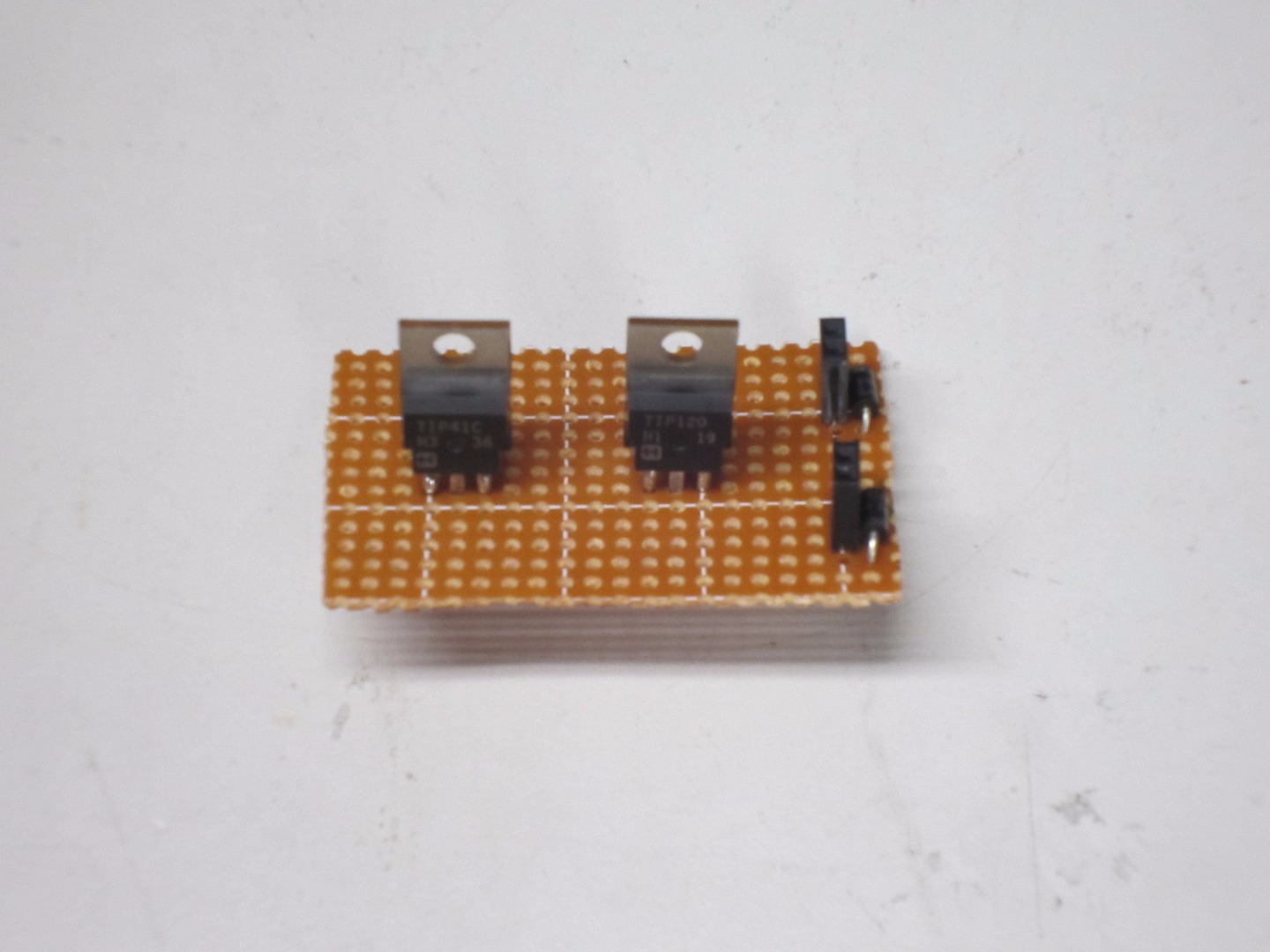
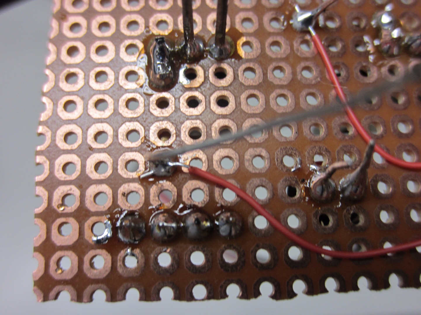
Solder the Transistors
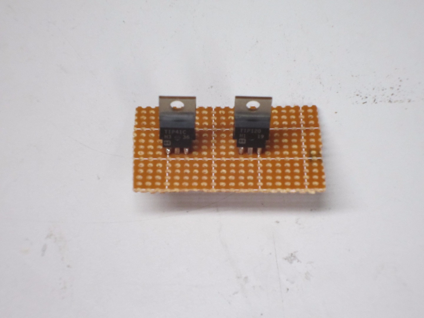
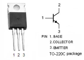
Start off by soldering the two power transistors on the PCB. Leave space between the two to make room for the other components. Don't trim the leads yet. After we make the connections to the transistor then you can cut off the leads. Take note of the transistor pinout above to avoid making the wrong connections. To get a better understanding of the circuit and how it works, it might be a good idea to prototype the circuit on a breadboard first.
Solder the Small Female Headers
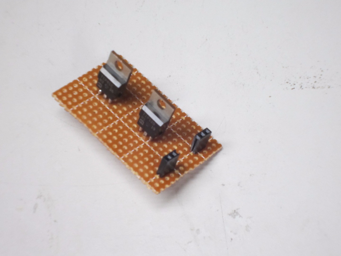
Solder on the small 1 x 2 female headers. Alternately, you could use screw terminals (I ended up switching the two out a the end) for an easier connection. Again, leave space between the headers and transistors for other components.
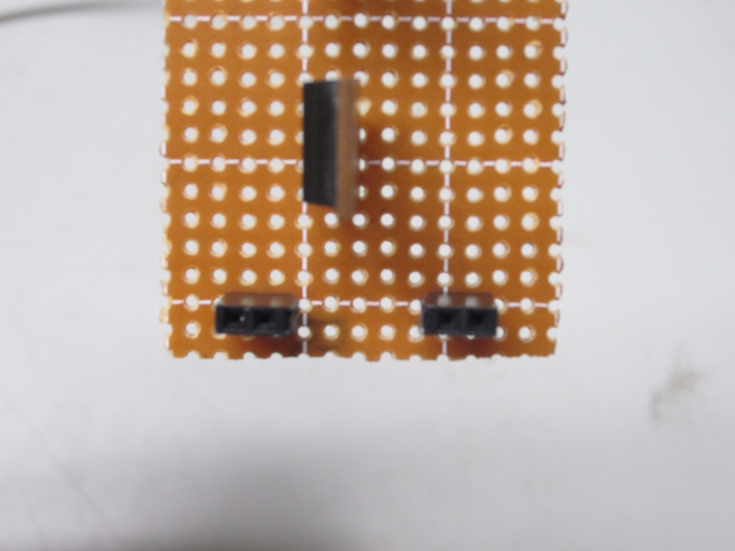
Solder the Diodes
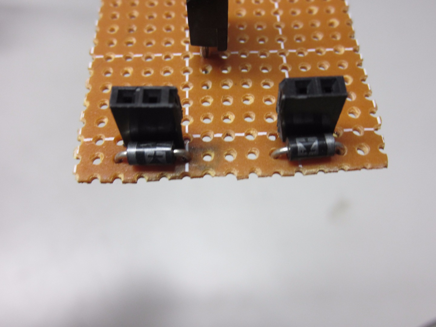
Solder the diodes on to the prefboard, in front of the small headers. Connect the diodes to the headers as shown in the 3rd above picture. This will prevent the motor from delivering high current to the board and ruining it. Trim the leads on all diodes. Ideally you should have the silver strip facing the top of the board, to make wiring the board easier.
Solder the LEDs
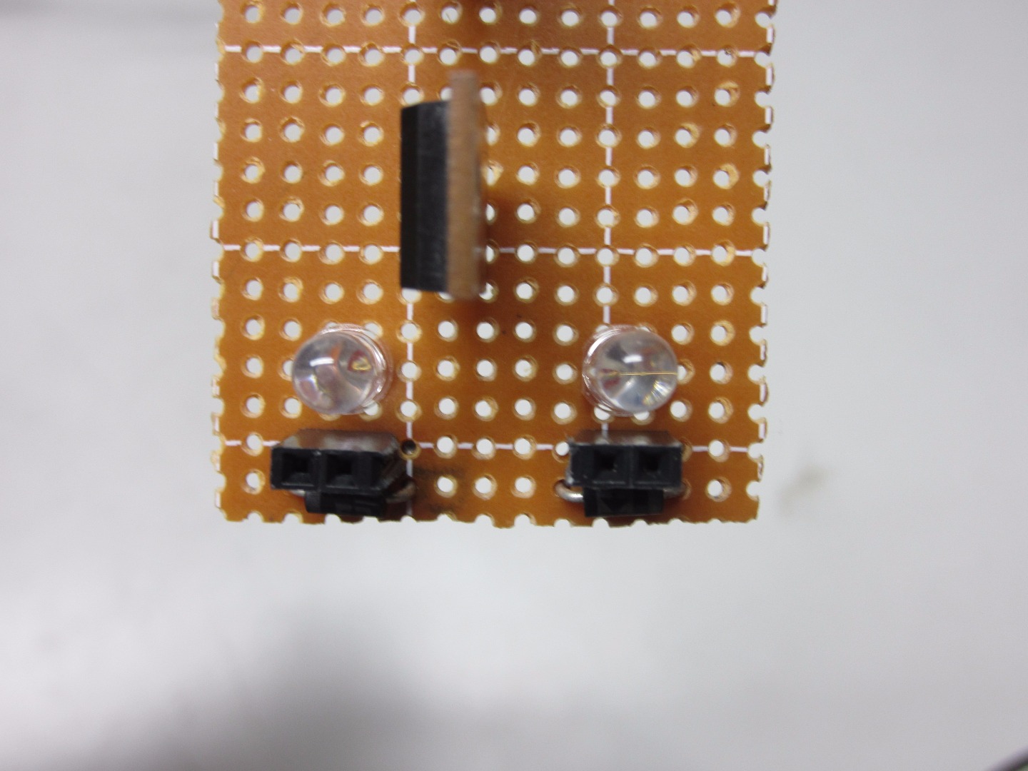
Solder on the LEDs in the back of the small headers. Any color you choose should work. You do not need to trim the leads or do any wiring yet. Keep in mind where you placed the anode and cathode for each.
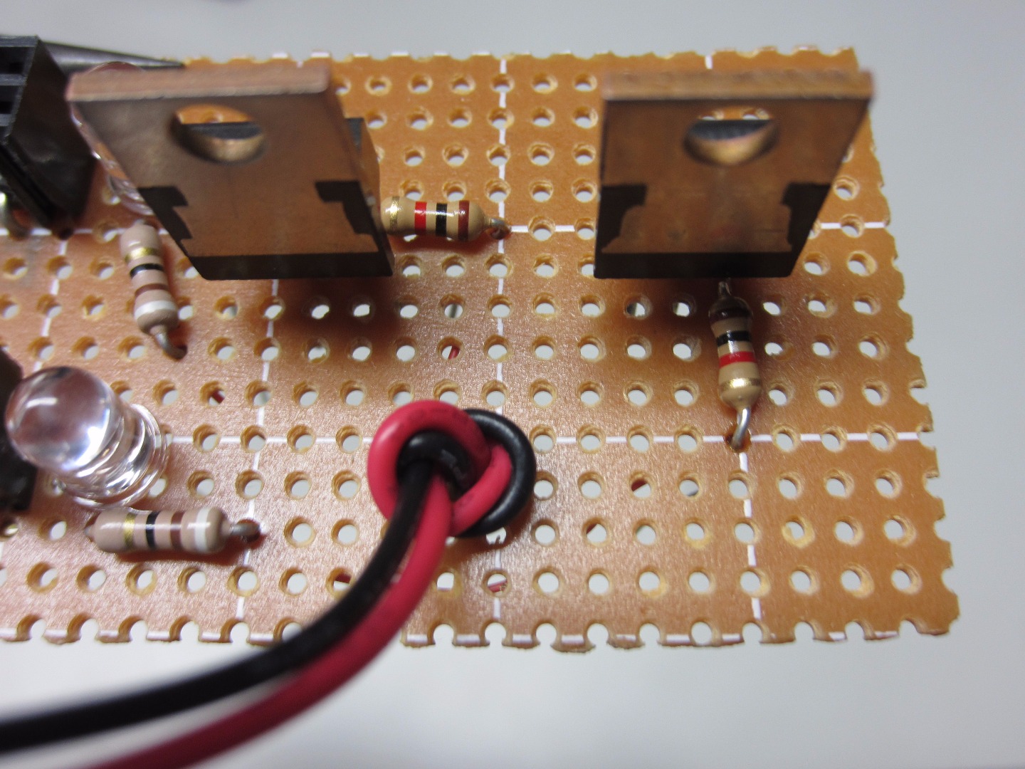
Solder the Base Resistors
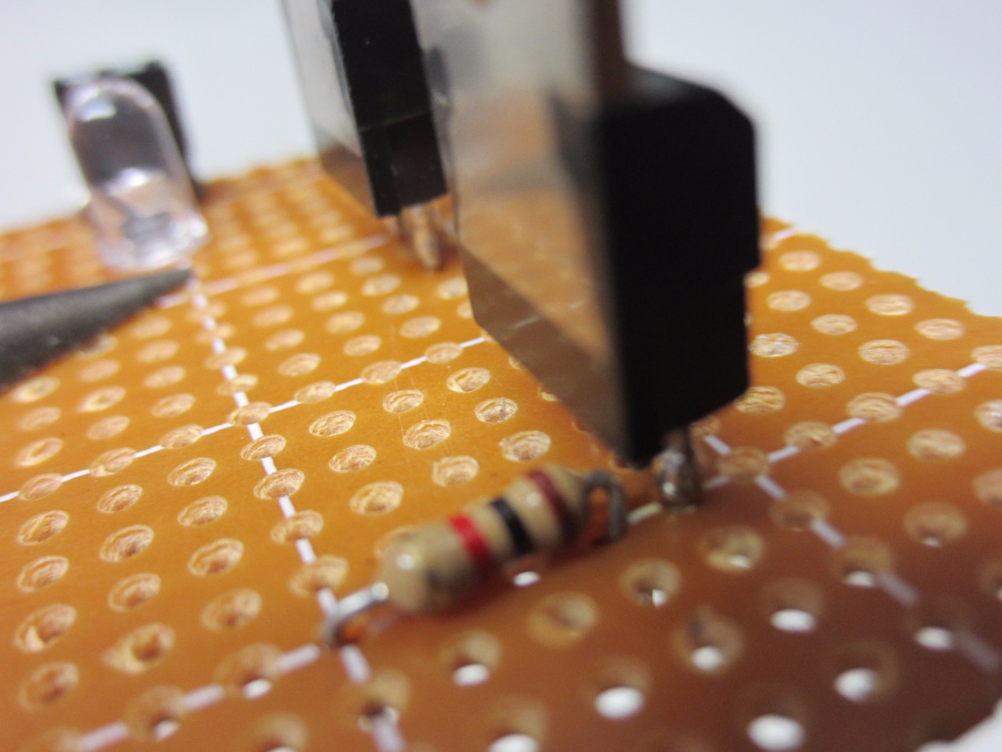
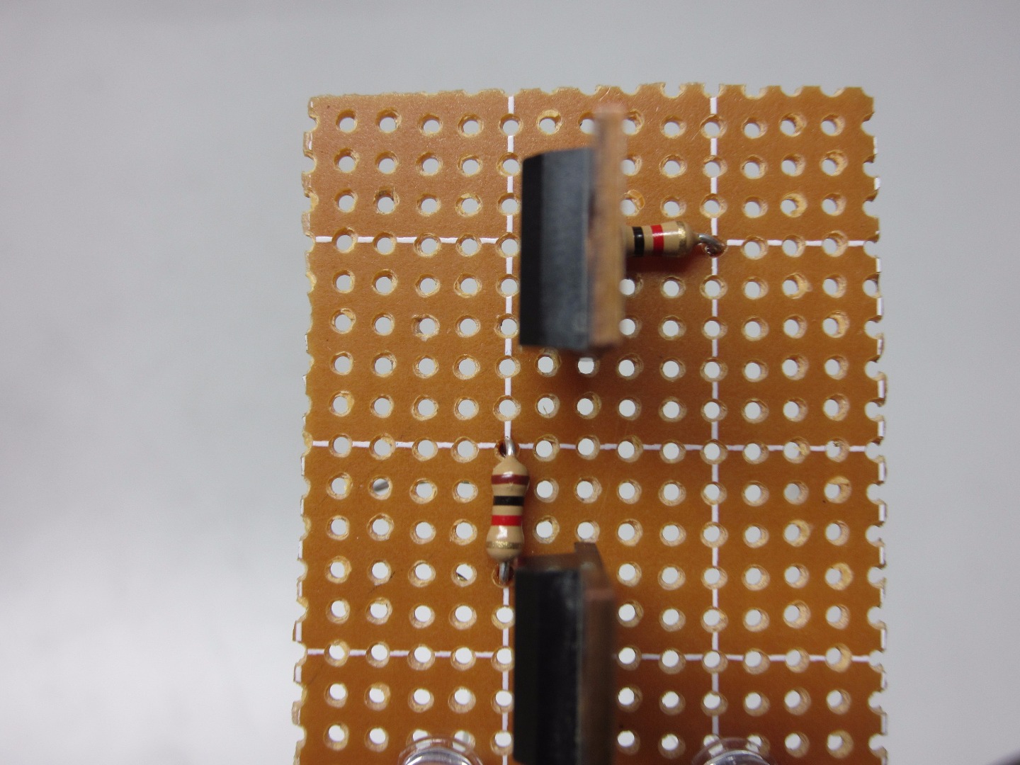
Solder the 1K resistors to the base (pin 1) of each transistor. Leave room in between the resistors, and do not connect it to anything. Cut the base lead and the resistor lead connected to it.
Solder the LED Resistors
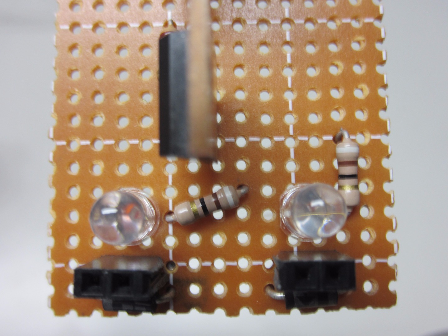
Solder the 100Ω resistor on the perfboard, with one of the leads connected to the LED's anode (longer lead). Trim the one resistor lead and anode lead.
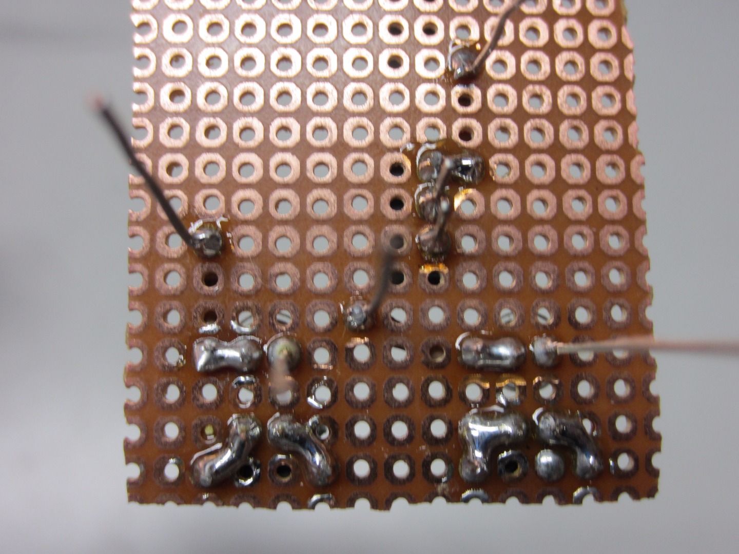
Connect the Resistors in Pairs
Connect the lead from one of the LED resistors to one of the transistor resistors. Trim off the lead from the LED resistor only. Repeat with the other 2 resistors to make 2 resistor pairs.
*Remember*** which resistor is connected to which! These pairs will always be separate; we are making 2 motor controllers!
Solder on External Power Supply Wires
Solder on the Power Supply wires. You can connect this to the power source of your choice (keeping in mind the motor and microcontroller volts and current). I connected a 9V battery clip so it can connect to a 9V or 12V source. Tie a knot near the base to prevent it from being pulled out.
*Optional*** drill a hole to slip the wires through to insure it will not come out.
Solder the Large Female Header
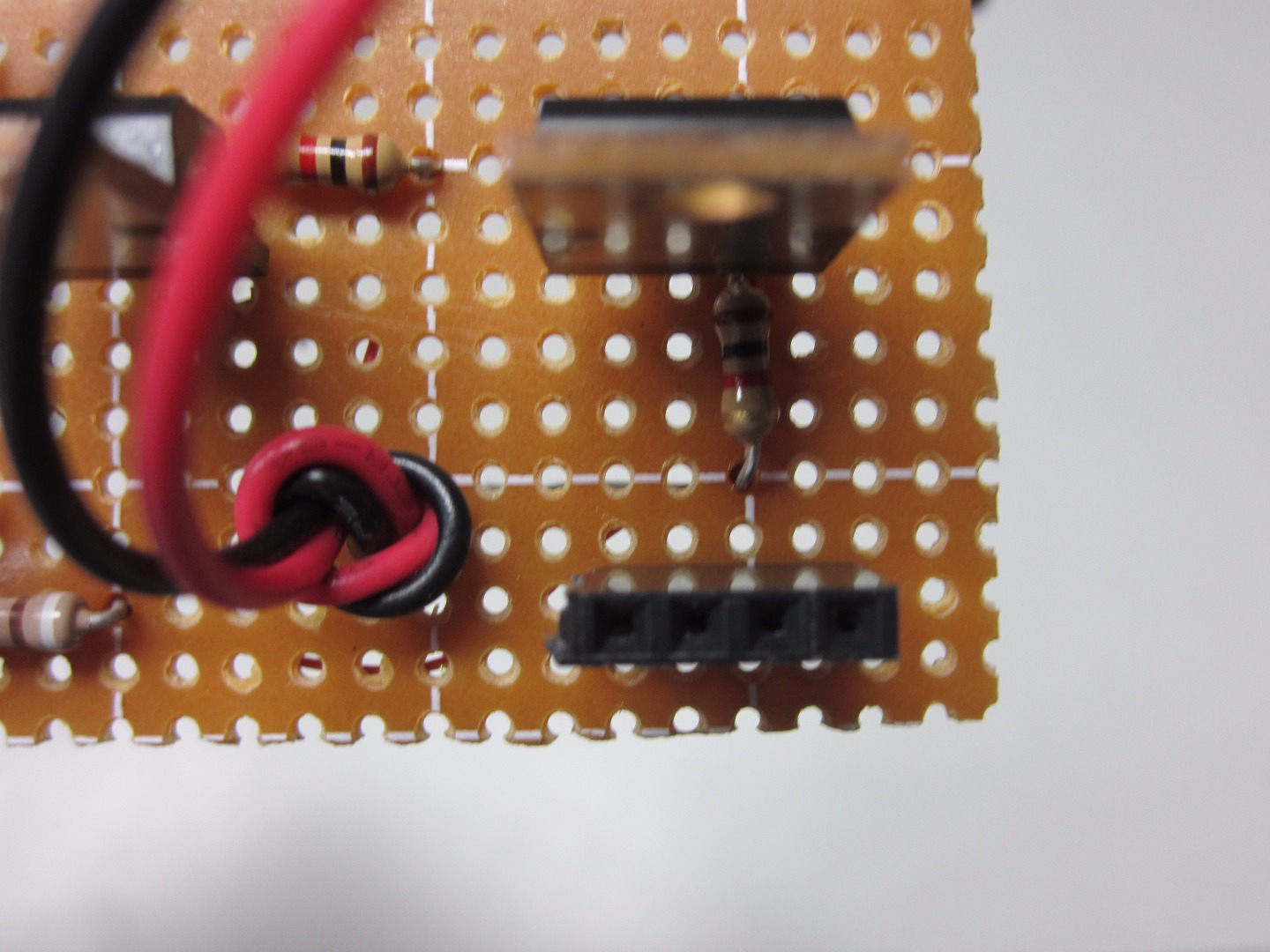
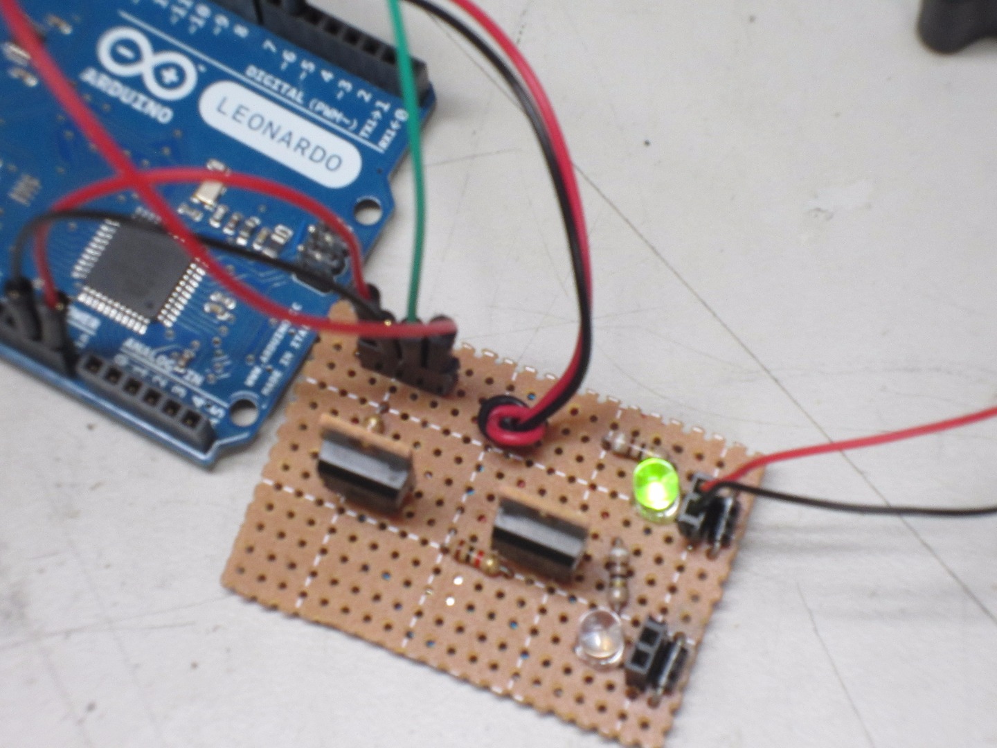
Solder the large female header on to the board, in the upper hand left corner. Connect the positive wire from the power supply to the farthest pin on the left (looking at it with the header in the upper left hand corner). Connect the negative Power Supply Wire to the pin next to the positive pin you just soldered. I used red wire for positive connections and blue for ground connections.
*Note*** This can be used to power a microcontroller or other accessory, and you can also use it as a power input if you wish to not use the attached Power Supply wires!
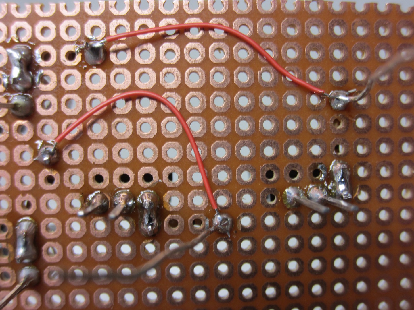
Connect the PWM Inputs
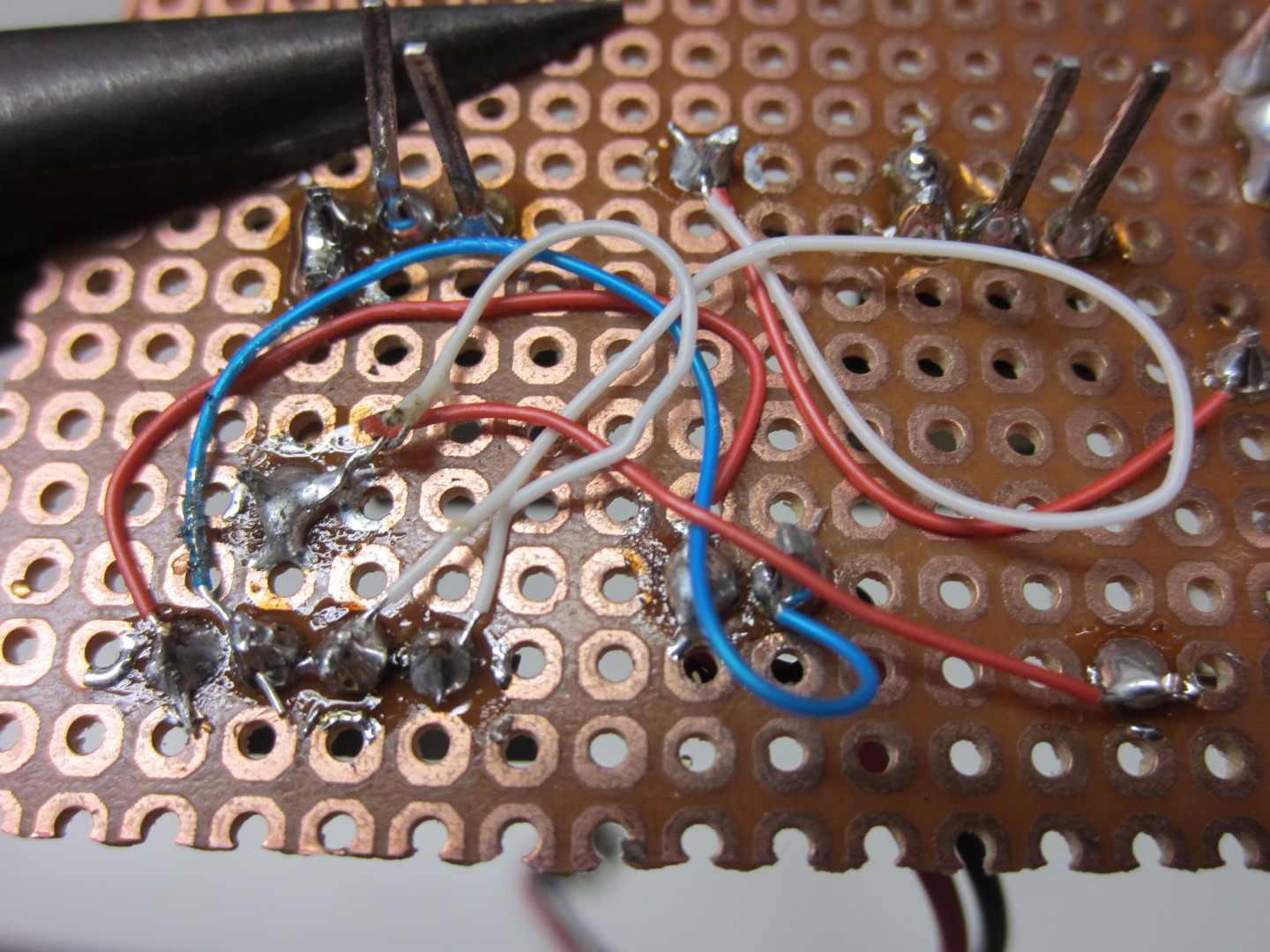
Connect the resistor connected to the Base (pin 1) of the Transistor to 1 of the available pins on the large header. Do this for the remaining resistor, connecting it to the last available pin. This large header will serve for inputs/outputs. Connect a PWM pin to the PWM input pins you just soldered, and use the power supply pins as an output or input for power. I used white wire for these connections
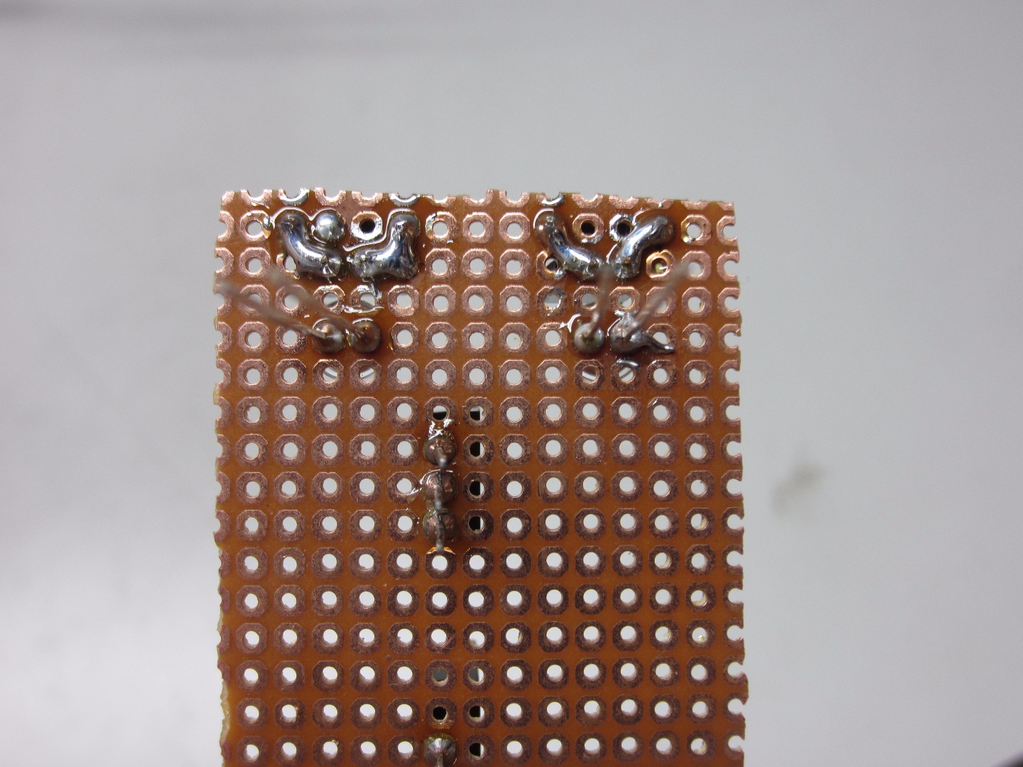
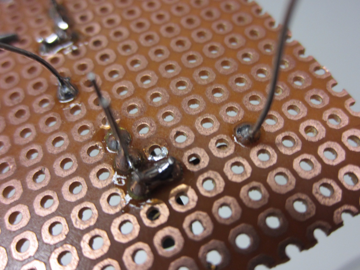
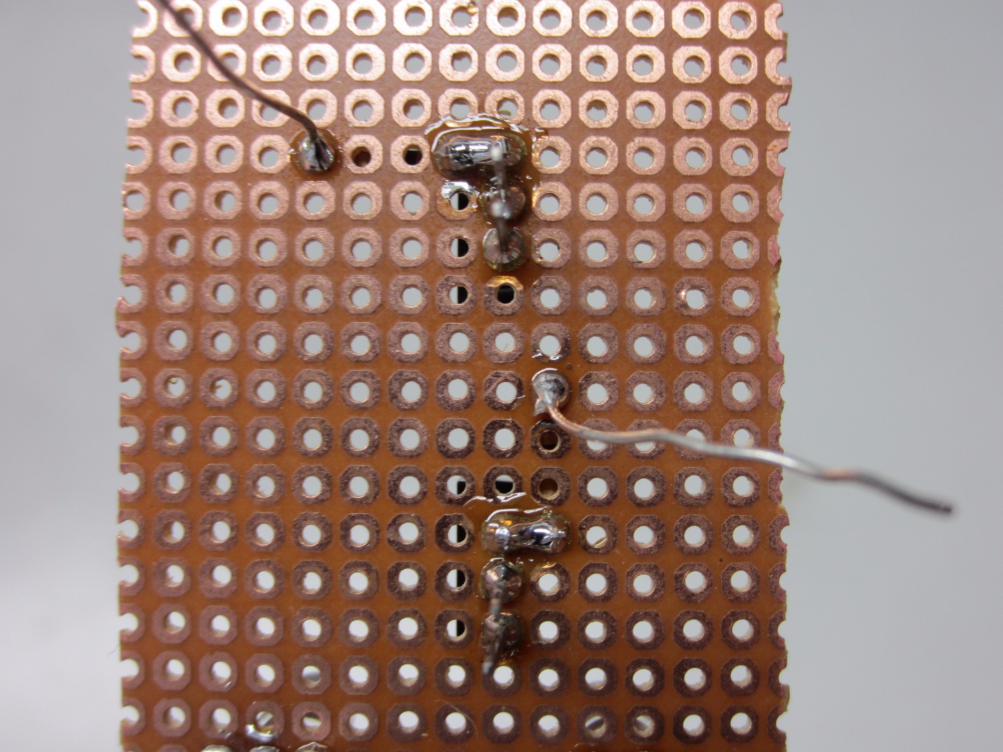
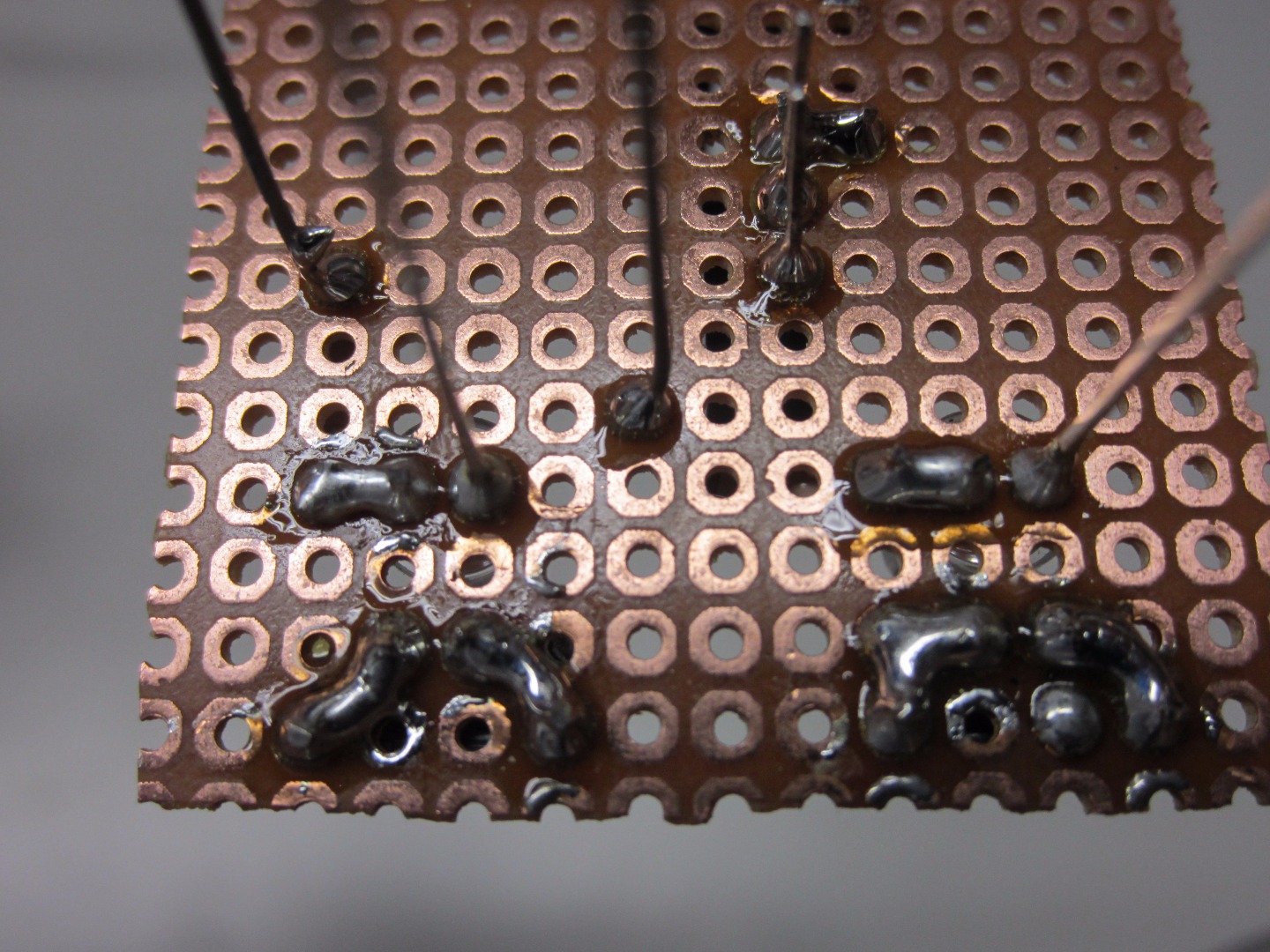
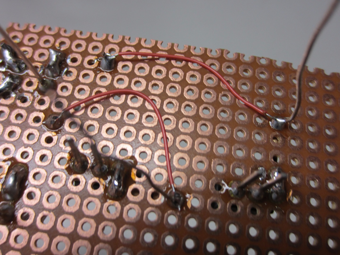
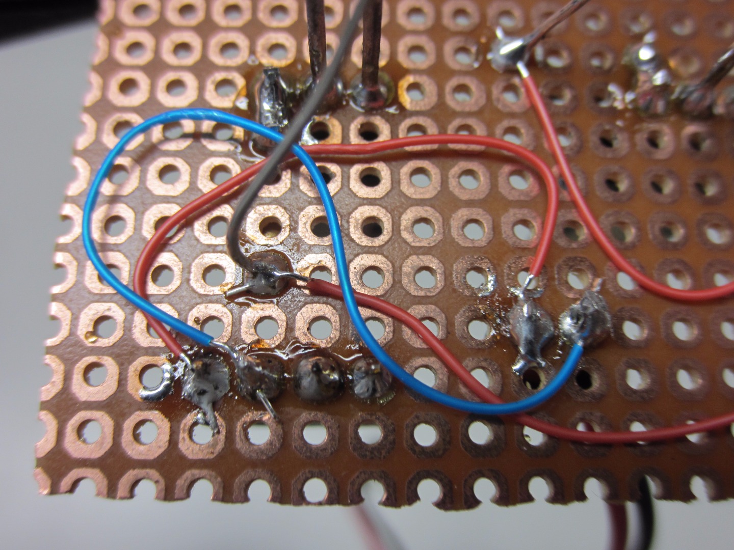
Ground Connections
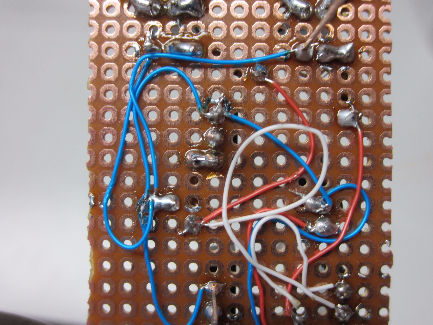
Connect the two Emitters of the Transistors (pin 3) to ground. Connect the two cathode leads of the LEDs to ground. Trim the Emitter leads and LED leads. I used blue wire for ground.
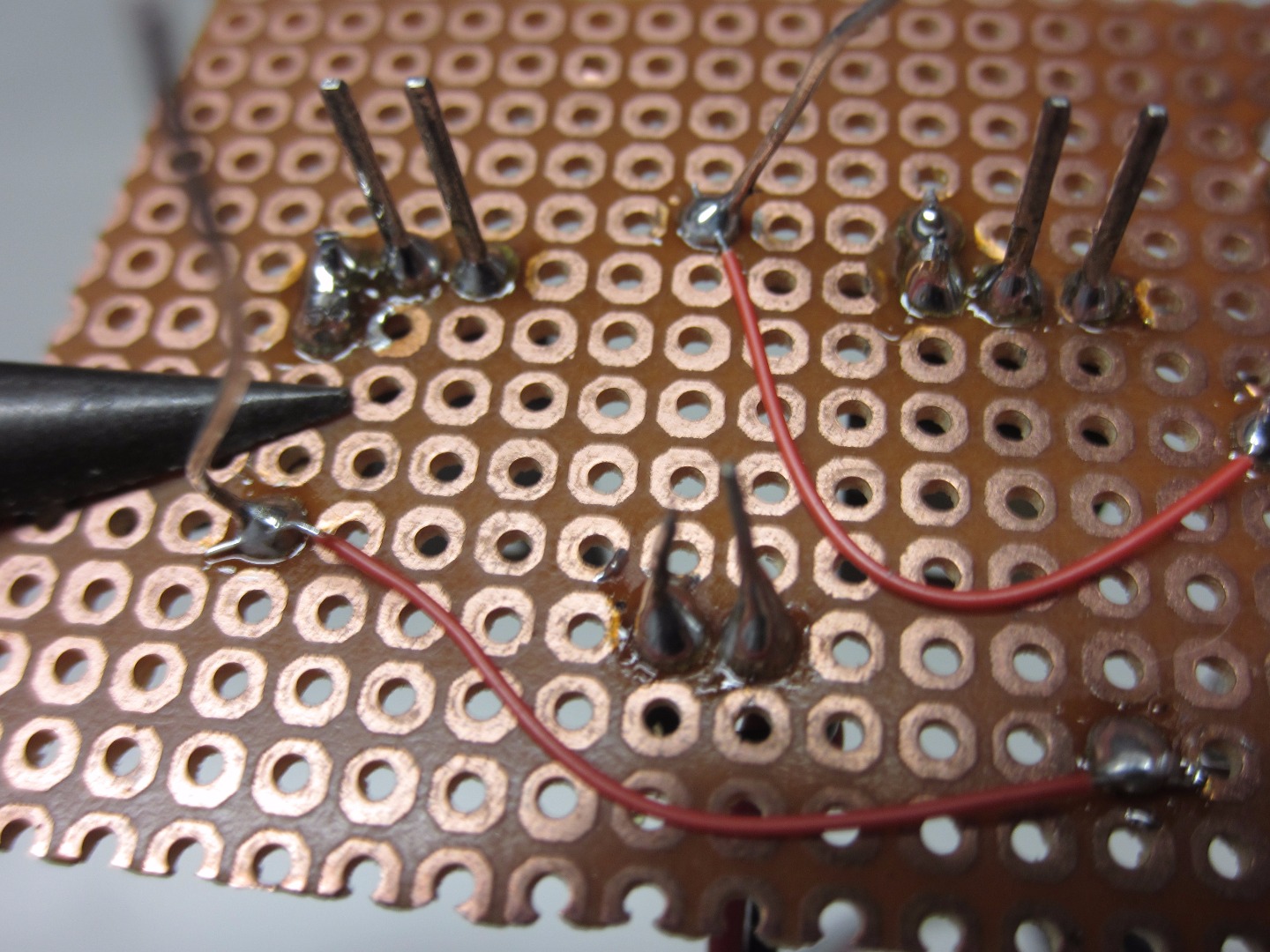
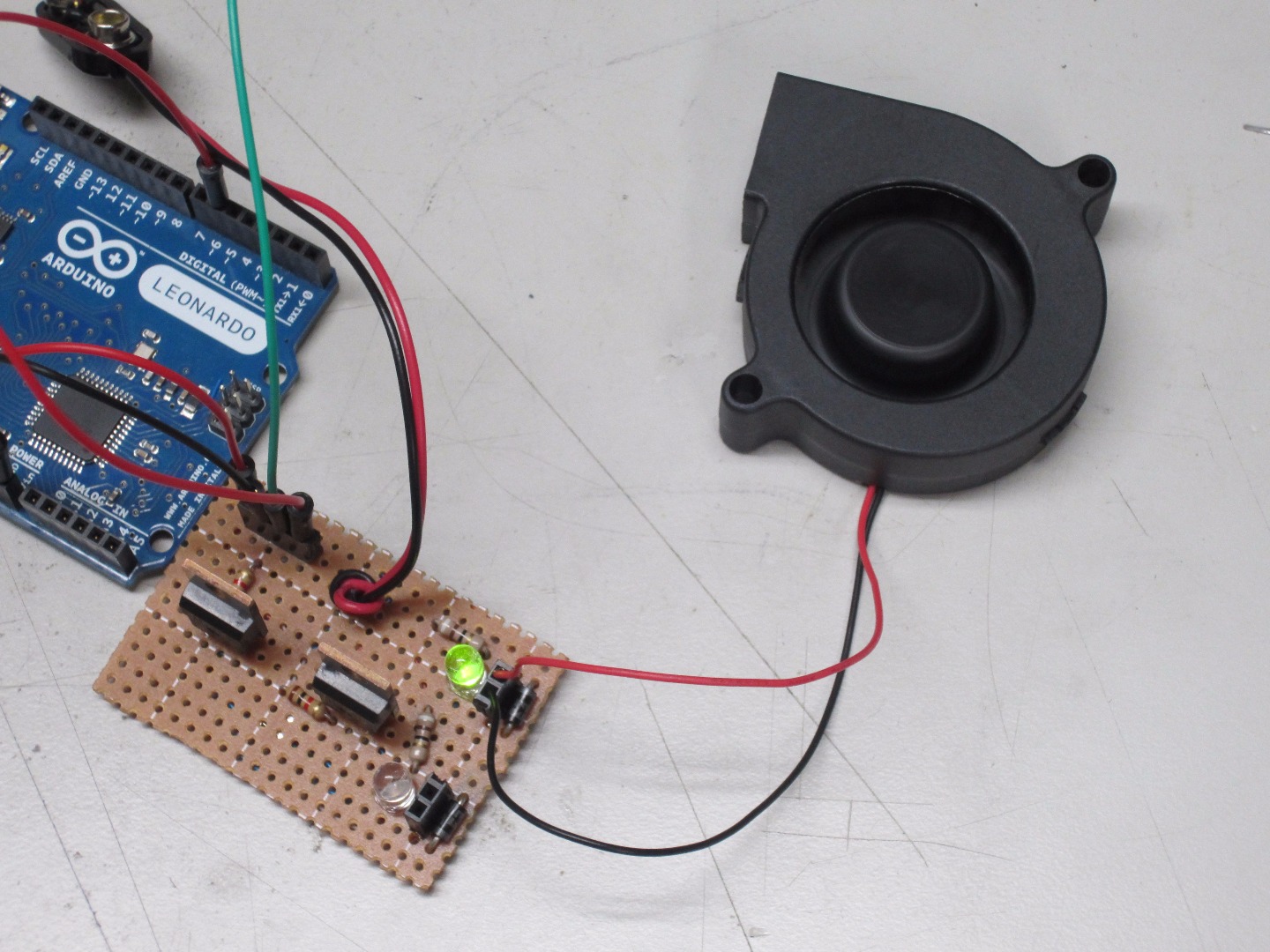
Connect Motor Pins to Power
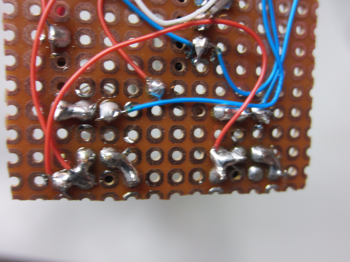
Connect the positive wire to the solder joint closest to the silver strip on the diode. Look at the pictures for reference, as this part can get tricky. Do this for both sets of headers.
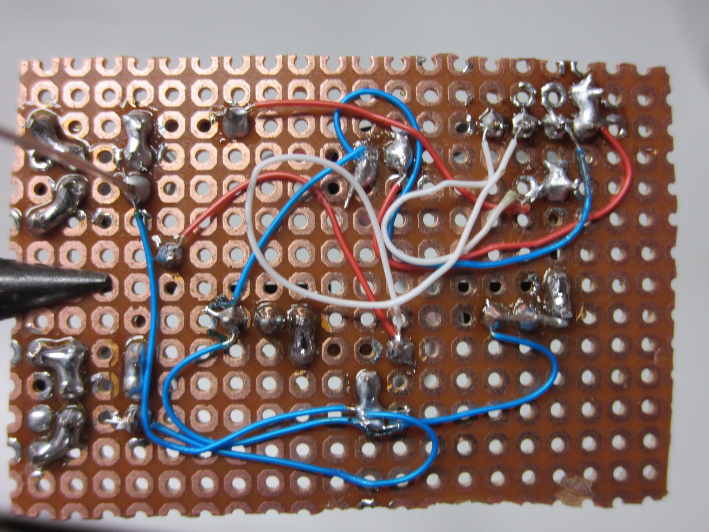
Connect Motor Pins to Collector of Transistor
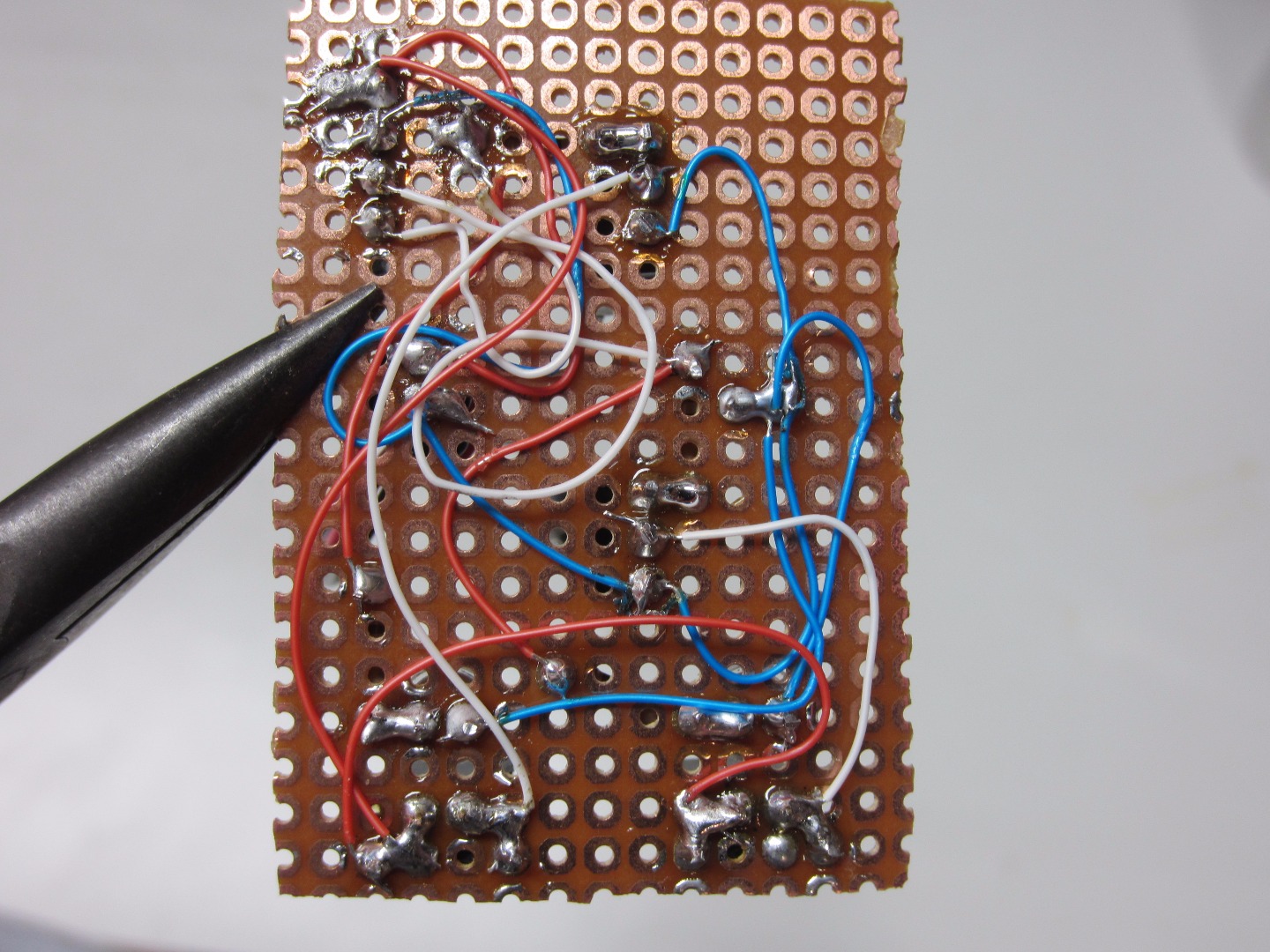
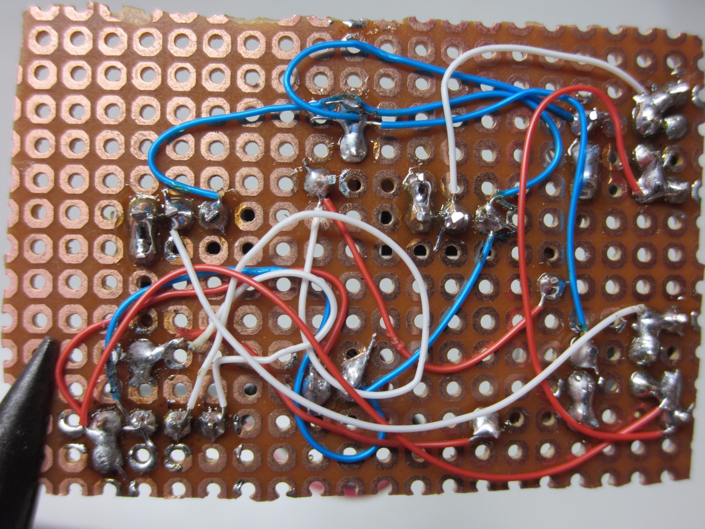
This is where remembering the pairs of resistors you made comes in handy. Choose a Motor connection header pin and figure out what transistor the LED near said header pin is connected to. Once you have done that, connect a wire from the remaining solder joint on said header pin and connect it to the collector (pin 2) of the transistor, that you just determined the LED is connected to. Trim the lead on the transistor, and repeat this for the other header and transistor. Use the pictures for reference.
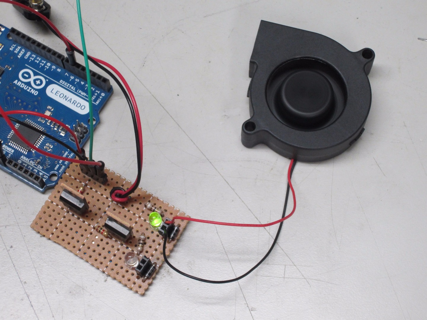
Upload the Code
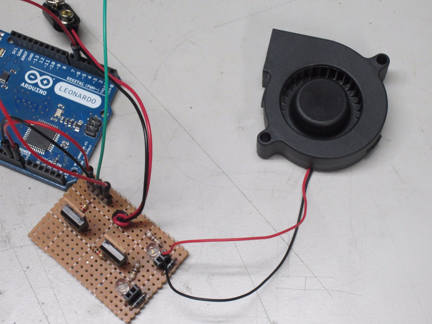
Now you have a simple motor controller shield. You can set the speed of the motor by sending an analog write command to the base of the transistor. Download and then upload the sample Arduino code given below to an Arduino board of your choice to test the motor controller. Try playing with the numbers and code to get comfortable using the speed controller.
To use this with other microcontrollers, make sure it has a PWM output, and set the output to match the required speed. If you do not know how to do this, find a sample code for controlling an LED, and change the code to serve your needs. Basically, you can somewhat think of this as controlling an LED; it takes the PWM signal and controls the motor with a higher voltage and current.