Mager Feeder
This is a guide on how to make the MagerFeeder project, which is a pet feeder that has a scheduling feature which allows it to be automatic and also a manual mode where the user sends a command through a bot to activate the device. Other features the device have includes, an ESP32-CAM module which is able to send the picture it takes to the user through the Telegram App, this allows the user to monitor the device and also their pet. A buzzer is also available as an indication that the device has been activated with a LED light that shows the device is on. Changin the setting of the device can be done using 4 buttons available at the top of the device, with a LCD screen for it's visual interface.
This project was made by BINUS UNIVERSITY Students:
- Billie Christianto - 2301855551
- Natario Thomas - 2301850065
- Febrioza Kevin Pratama - 2301872495
Supplies
- Arduino UNO
- Breadboard
- LCD 16x2
- Push Button (x4)
- Motor Servo SG90
- ESP32-CAM
- RTC DS1307
- FTDI Programmer
- PIR Sensor
- LED
- Buzzer
- Jumper Wire
- PVC Pipe
- Plastic Container
- Case
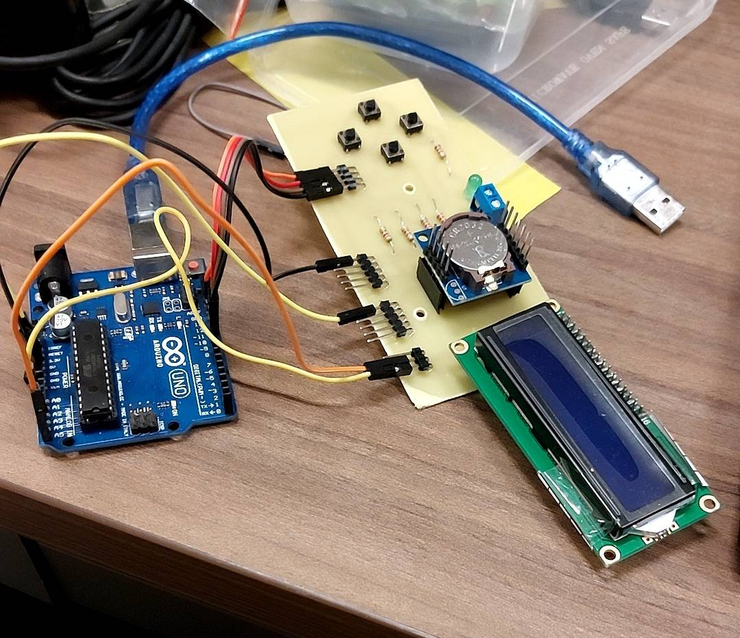
Setting Up the Components
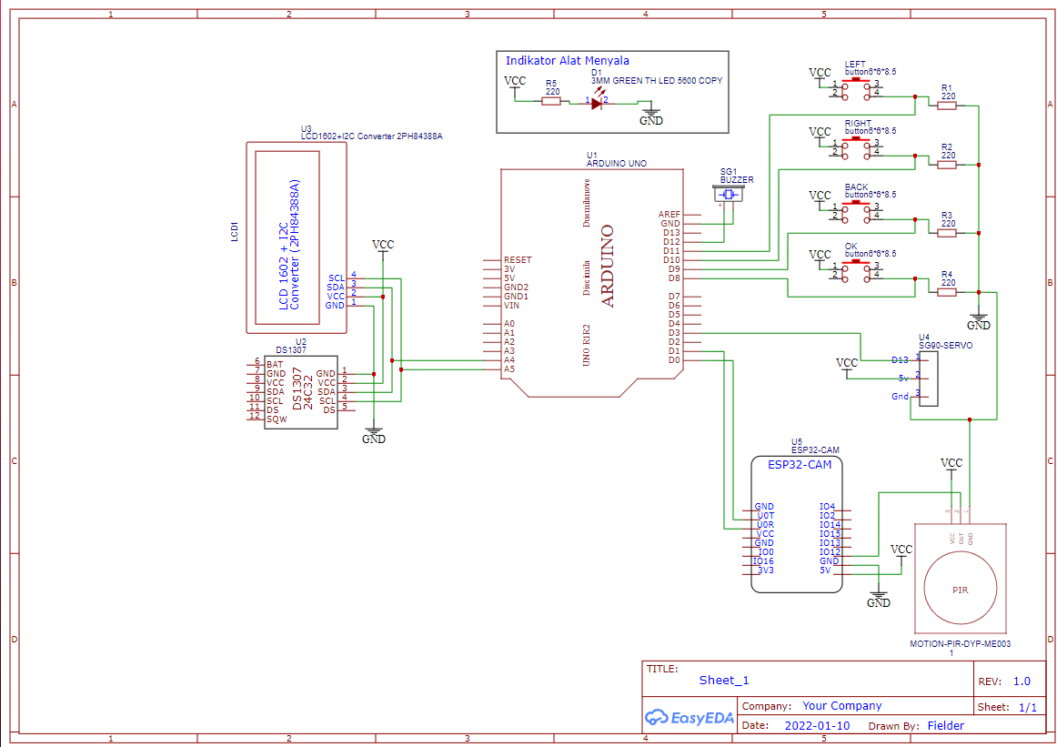
The above picture is the schematic for the Mager Feeder project
Making the PCB
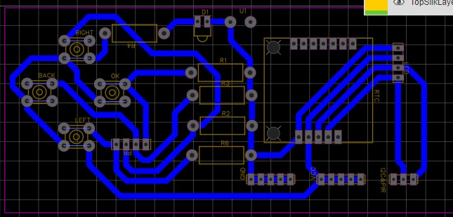
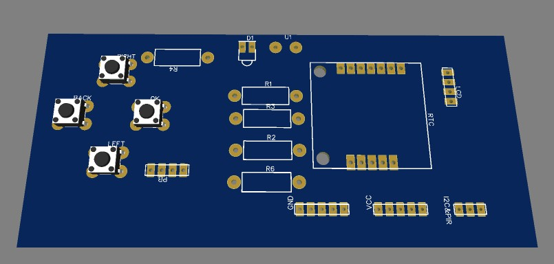
The above pictures contain the PCB layout for components such as the LCD, Push Button, RTC, Buzzer, and Resistor
Making the Bot
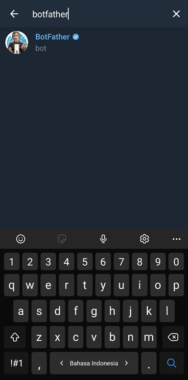


- Login into a Telegram account and search the "BotFather" account as shown in the first picture
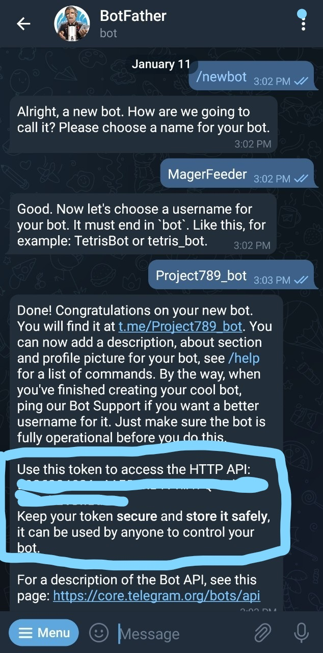
- Send these messages:
- /newbot = Command to create a new bot
- BotFather will ask a name for the bot that you want to create
- Here, we will type "MagerFeeder" as our bot name
- You will then be asked to make a username for the bot. Make sure that the username is unique, here we will use "Project789_bot" as the username
- BotFather will send the bot token to be used in the next step
- Copy the bot token that you recevied as shown in the second picture and paste it in line 17 of the ESP32-CAM code
- Go back to Telegram and search an account with the name of "get id bot" as shown in the third picture
- Send the command "/my_id" and wait for it to response. Copy your Chat ID and paste it into line 16 of the ESP32-CAM code
Writing the Code
- 1. Arduino UNO Code
The first file contains the code for the Arduino - 2. ESP32-CAM Code
The second file contains the code for the ESP32-CAM
Libraries Needed:
- Arduino UNO
- Wire.h
Link: https://github.com/esp8266/Arduino/blob/master/libraries/Wire/Wire - LiquidCrystal_I2C.h
Link: https://github.com/johnrickman/LiquidCrystal_I2C - Servo.h
Link: https://github.com/arduino-libraries/Servo - RTClib.h
Link: https://github.com/adafruit/RTClib
- Wire.h
- ESP32-CAM
- Universal Telegram Bot
Link: https://github.com/witnessmenow/Universal-Arduino... - Arduino JSON
Link: https://github.com/bblanchon/ArduinoJson
- Universal Telegram Bot
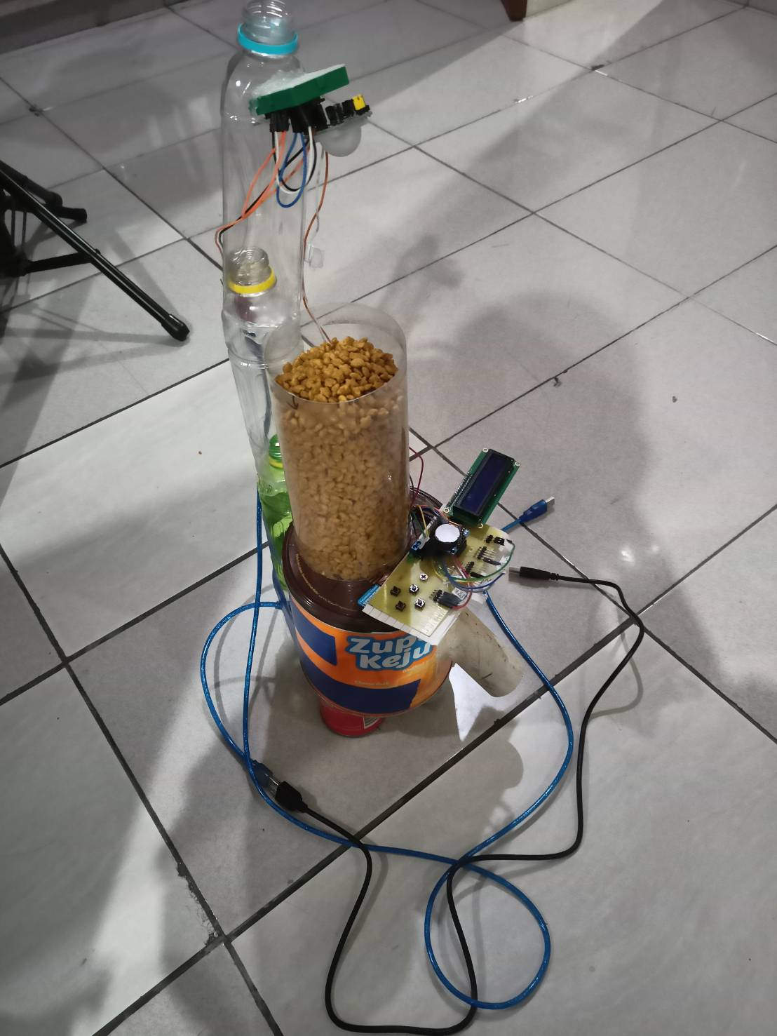
Assembling the Device
- Prepare all the needed tools and materials
- Make a hole in the middle of the casing for the PVC pipe which will serve as our food track
- Make a hole at the top of the case for wiring, motor servo, and also to connect the container to the PVC pipe
- Make a hole at the bottom of the container for the motor servo and also where the food will go through
- Connect the food container with the top of the case using the body of the motor servo at the bottom side and the propeller at the top side
- Make a pole / pillar to place the ESP32-CAM above the device
- Place the ESP32-CAM at the pillar and position it so the camera is facing the food container
- Place the assembled arduino according to the schematic into the case
- Make a hole at the back side of the case to connect the arduino cable
- Place the PCB at the front end of the top of the case
- Assemble the case
- Fill the container with pet food
How It Works
Video on How to Use the Device:
https://binusianorg-my.sharepoint.com/personal/bil...