Folding Sunglasses Made in Fusion 360
by alamtania in Circuits > Software
4725 Views, 21 Favorites, 0 Comments
Folding Sunglasses Made in Fusion 360
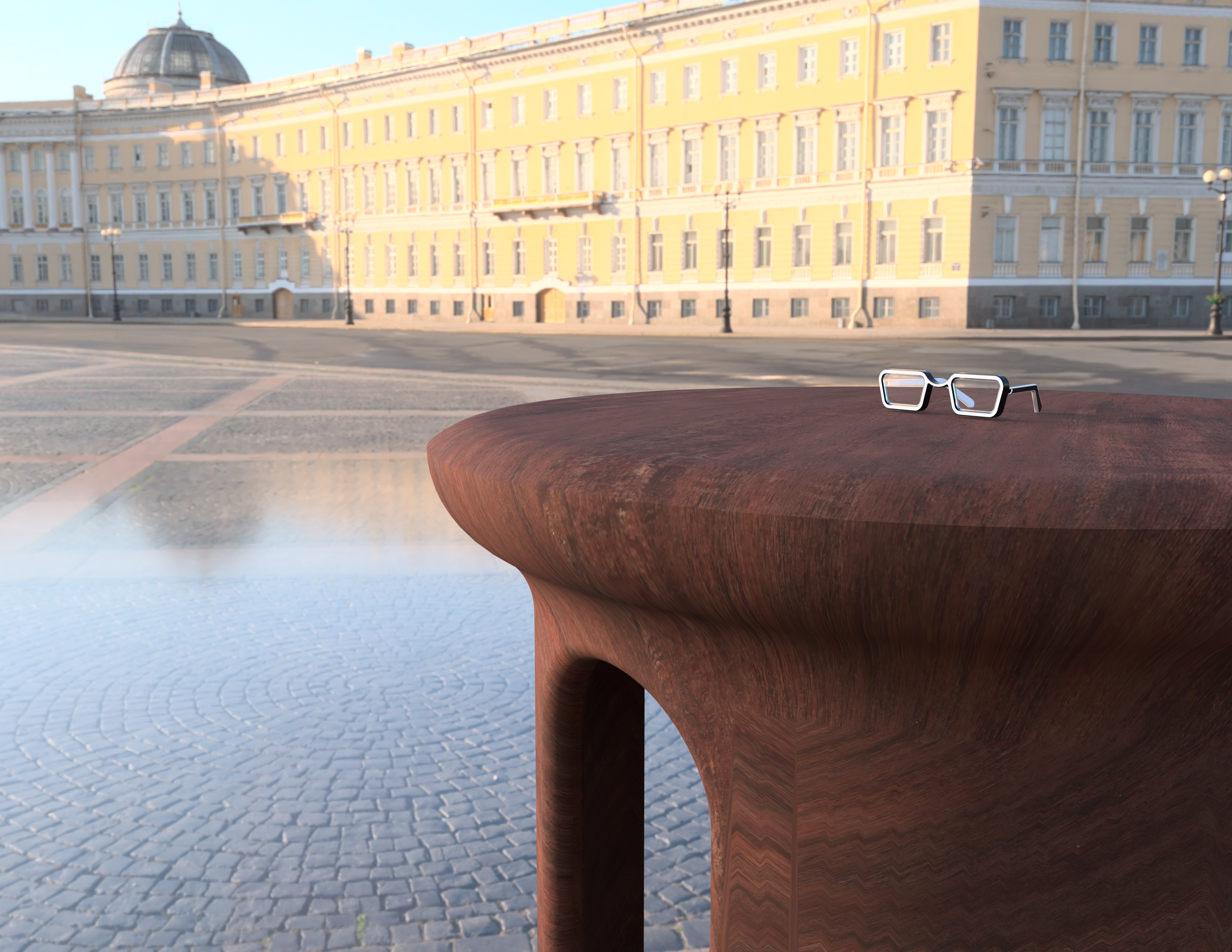
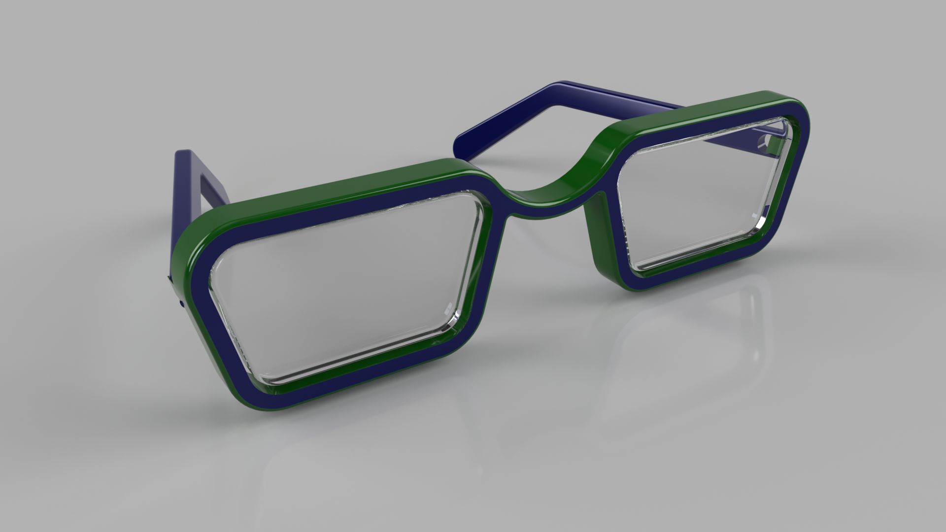
This project is a development of my previous sunglass model . The previous model had fixed hands but this one can fold it's hands. Curious to know how? Follow on.
Software required:
Fusion 360 by Autodesk
Pre-requisites:
Although the Instructables is meant to be for beginners, it is recommended to have some basic knowledge of the software.
Lessons recommended:
Fusion 360 class (Lessons: 1-5 and 9)
Create the Frame and Lens
.png)
.png)
.png)
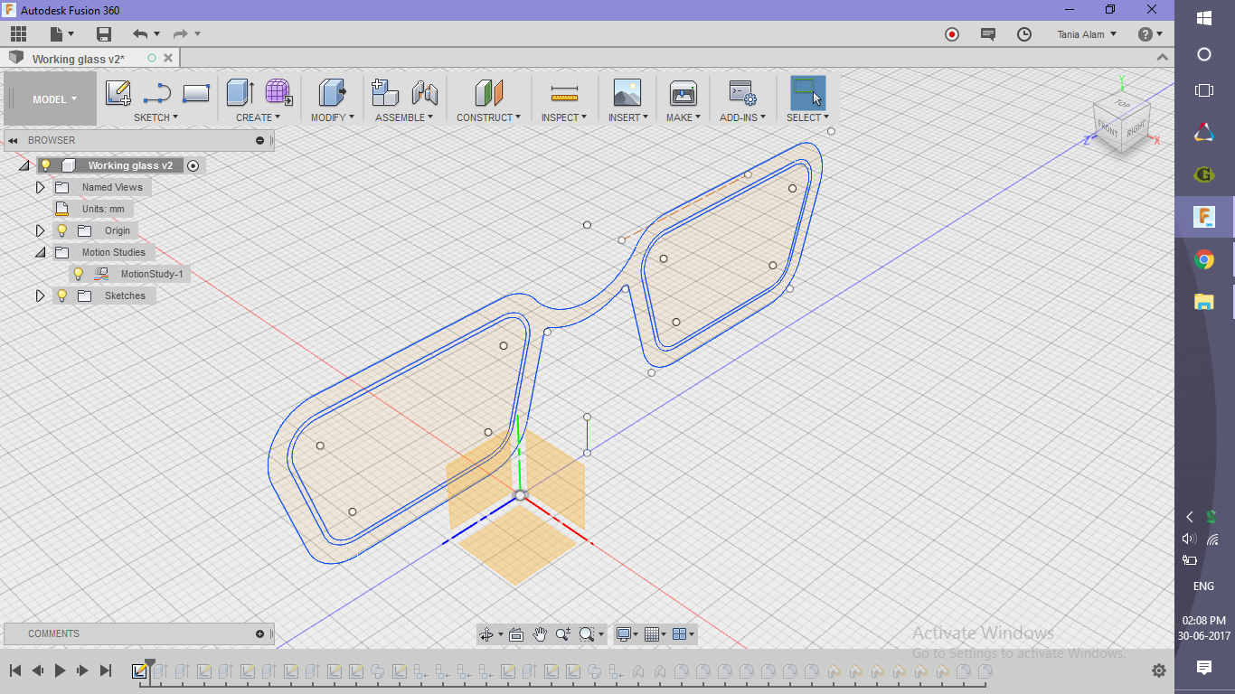
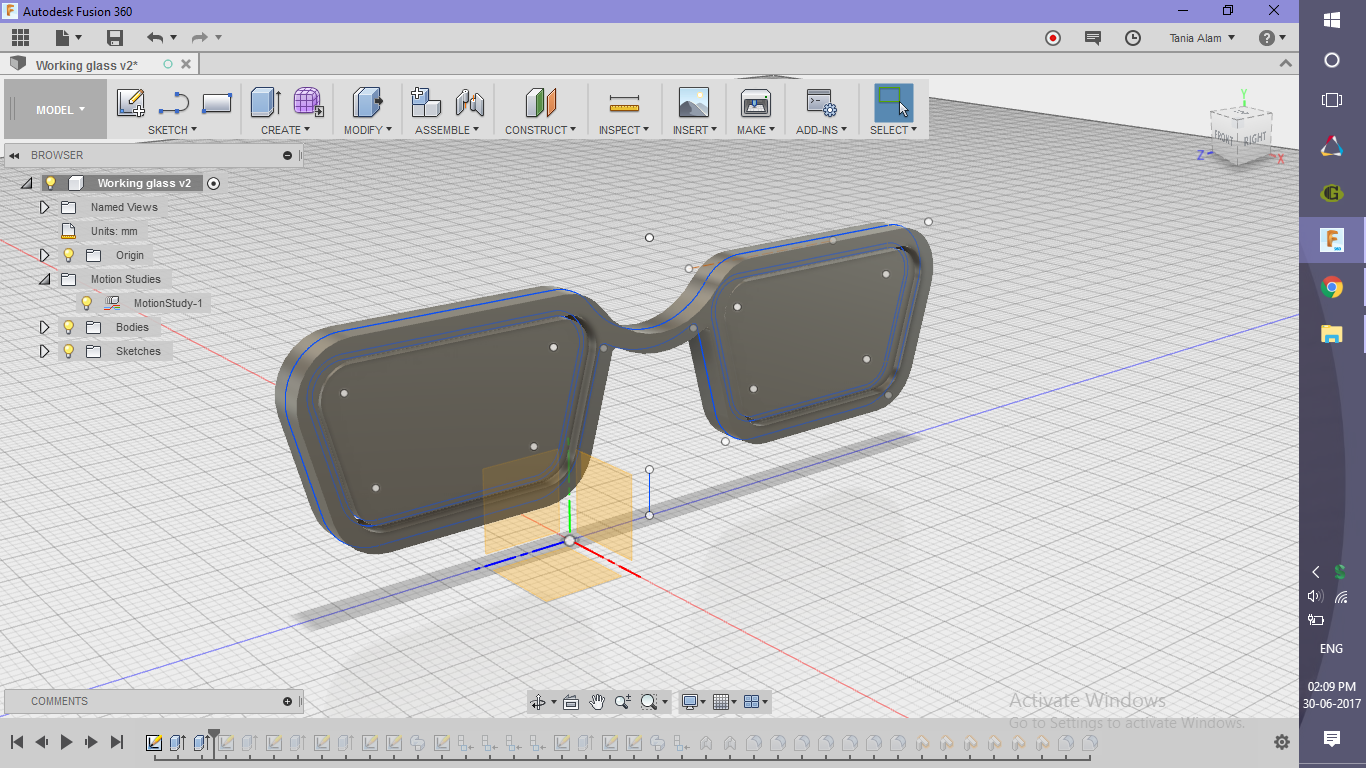
- Sketch the profiles
- Use lines to draw a rectangle
- Apply constraints to make it a trapezium
- Apply fillets to the ends
- Offset the sketch by 2 mm outside and 0.5 mm inside
- Mirror the sketch using a central line to avoid drawing the same thing for the other side
- Use arc to connect the sketches
- Trim off unnecessary lines
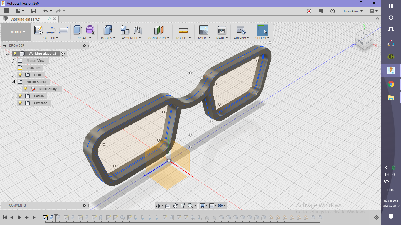
- Extrude the outer profile for the frame to 2mm on both sides (Check on the "Symmetric" option)
- Extrude the inner profile o 0.5 mm on both sides for the look of the glasses
Create the Connection
.png)
.png)
.png)
.png)
.png)
.png)
.png)
.png)
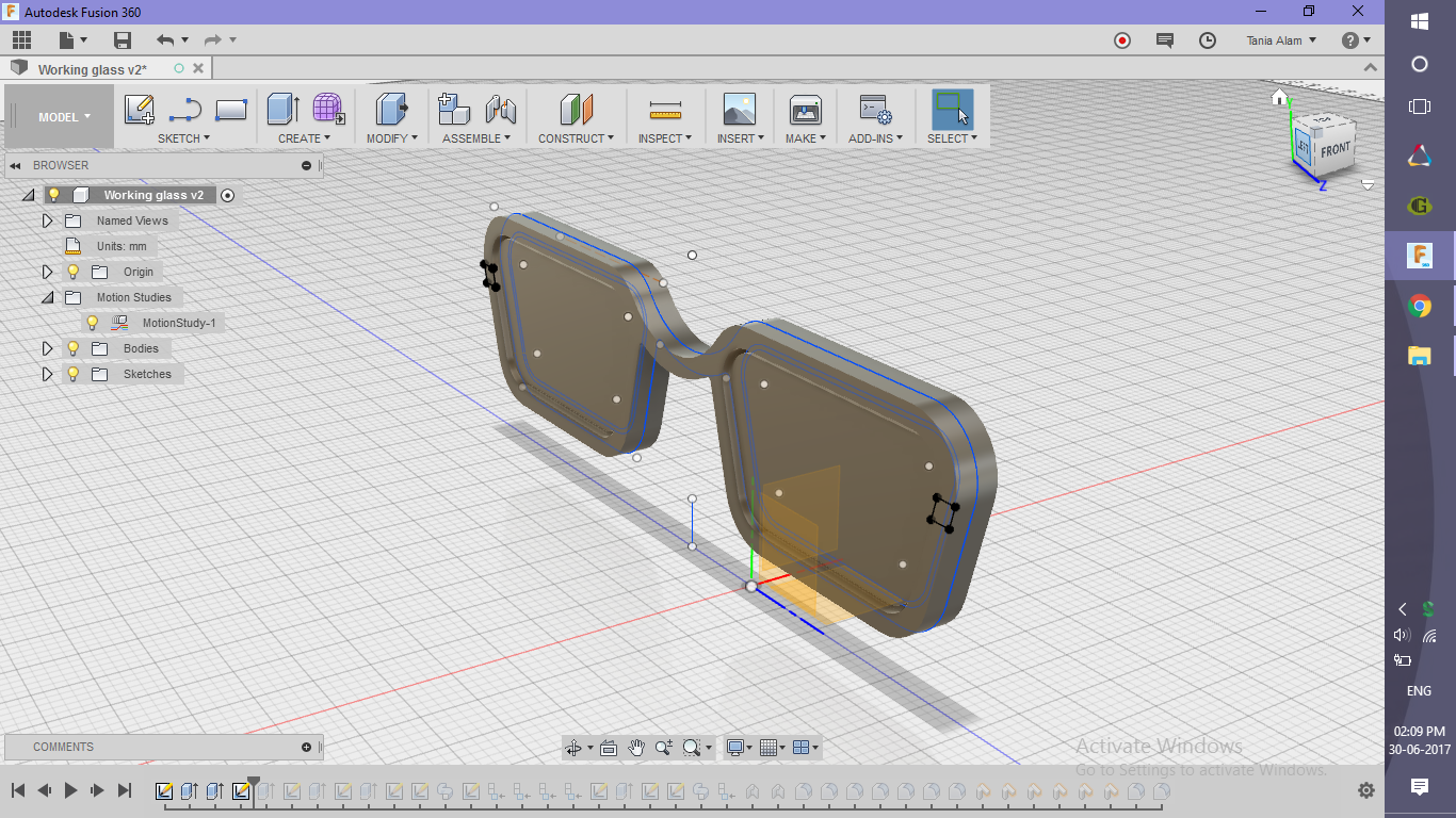
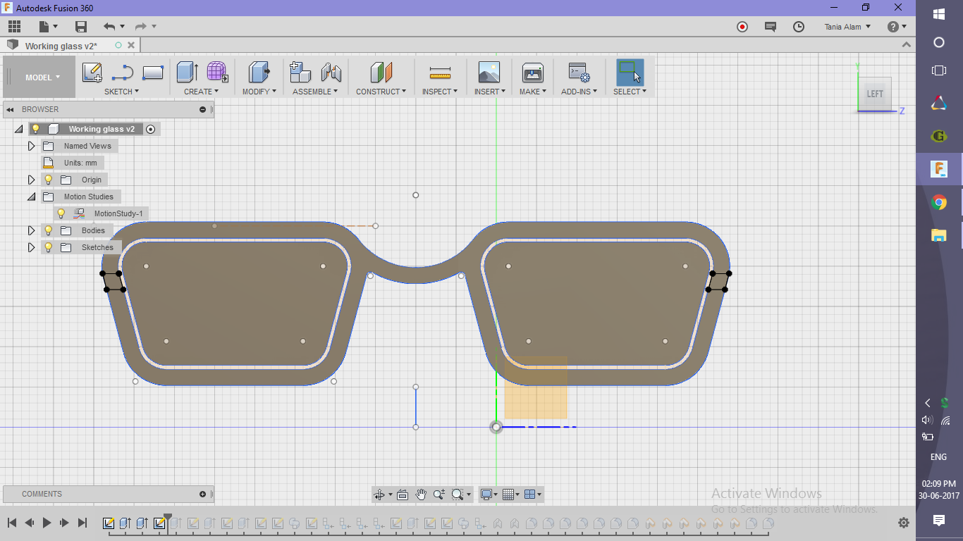
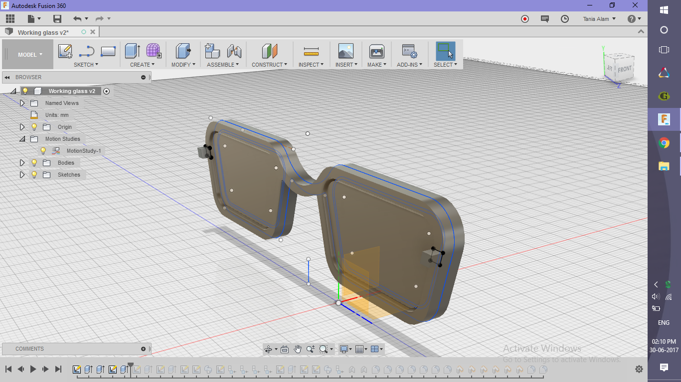
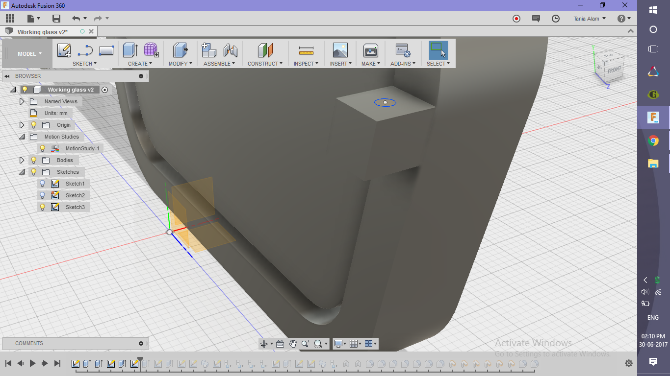
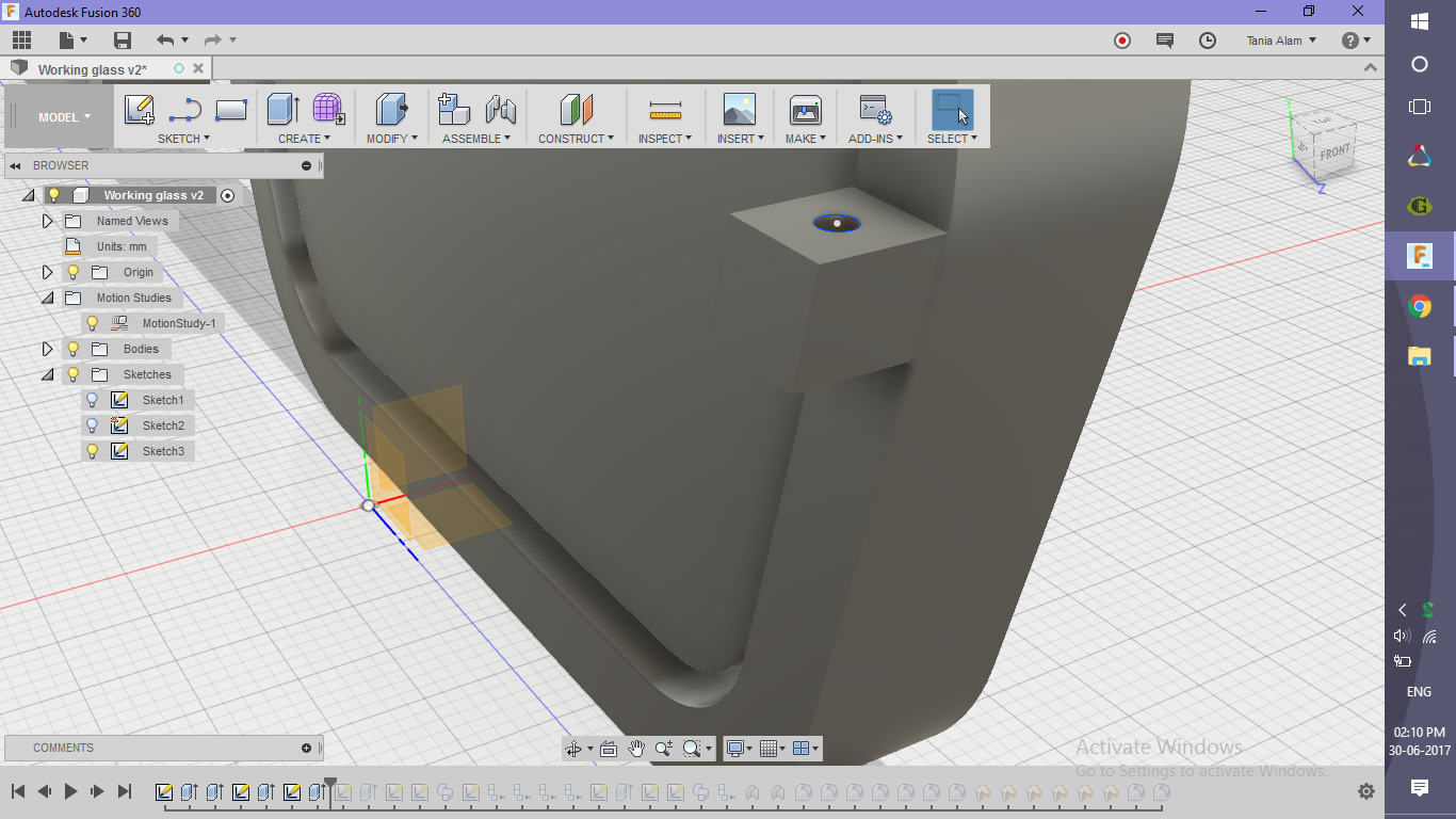
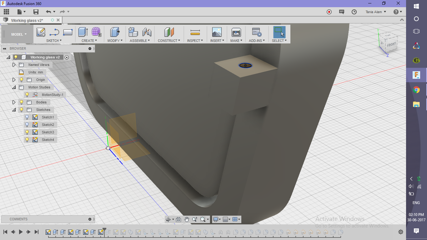
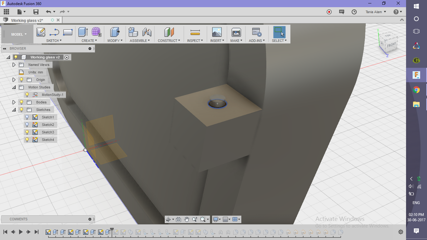
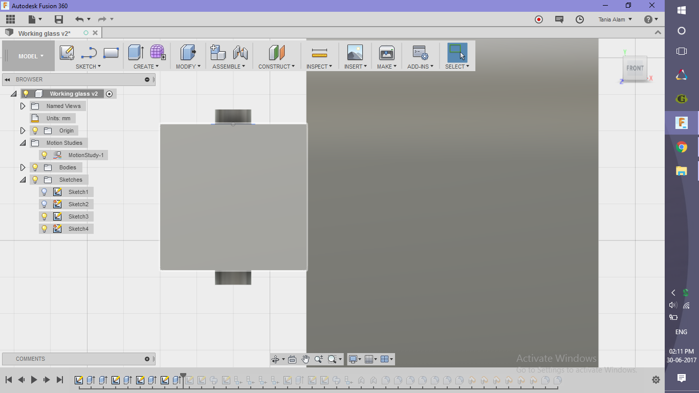
If the sunglass needs to be working, it needs a connection where the frame and the hands will be joined. To make this connection, follow these steps:
- Create a quadrilateral using the back of the frame as the sketch plane
- Extrude it to 2 mm
- Create a cylindrical hole through it
- Sketch a small circle on it's top surface
- Extrude it to cut the part
- Create a cylindrical rod through the hole (
- Sketch a circle (slightly smaller than the one you just created) on it's top surface
- Extrude it on both sides
Create the Hands
.png)
.png)
.png)
.png)
.png)
.png)
.png)
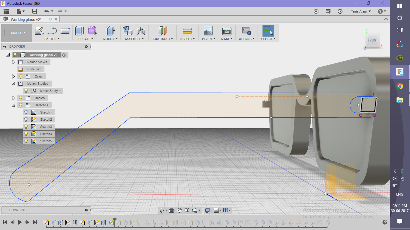
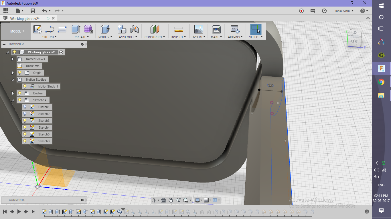
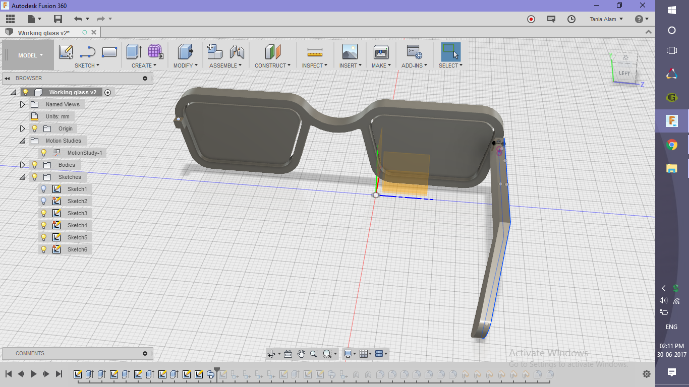
Now, that you have made the connection, you need to sketch out the hands as well.
- Sketch the profile of the hand using the lateral side of the frame as the sketch plane
- Create a rectangle with a length much greater than it's breadth
- Draw some inclined lines from the ends of the cylinder
- Join the two lines using an arc
- Create a line denoting the path through which it should get extruded
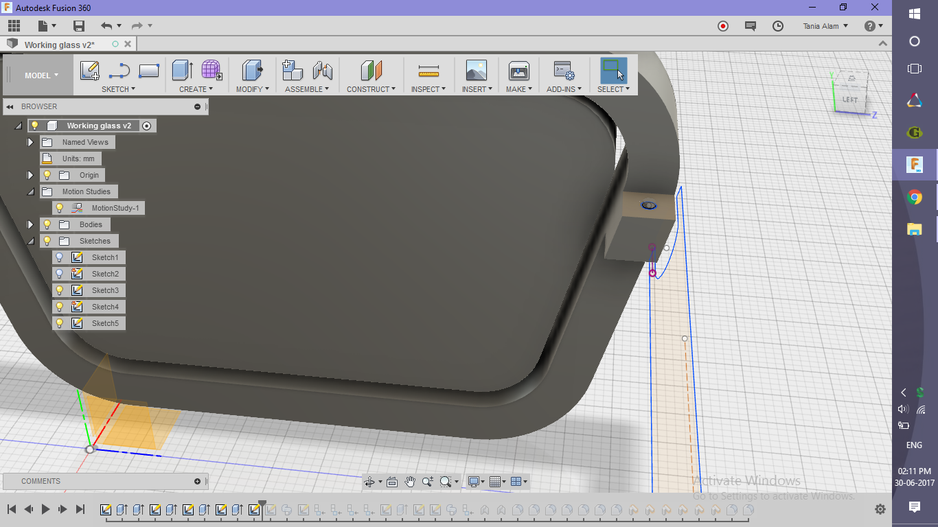
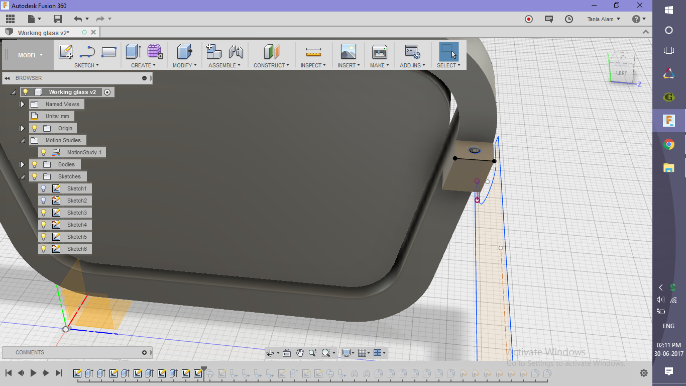
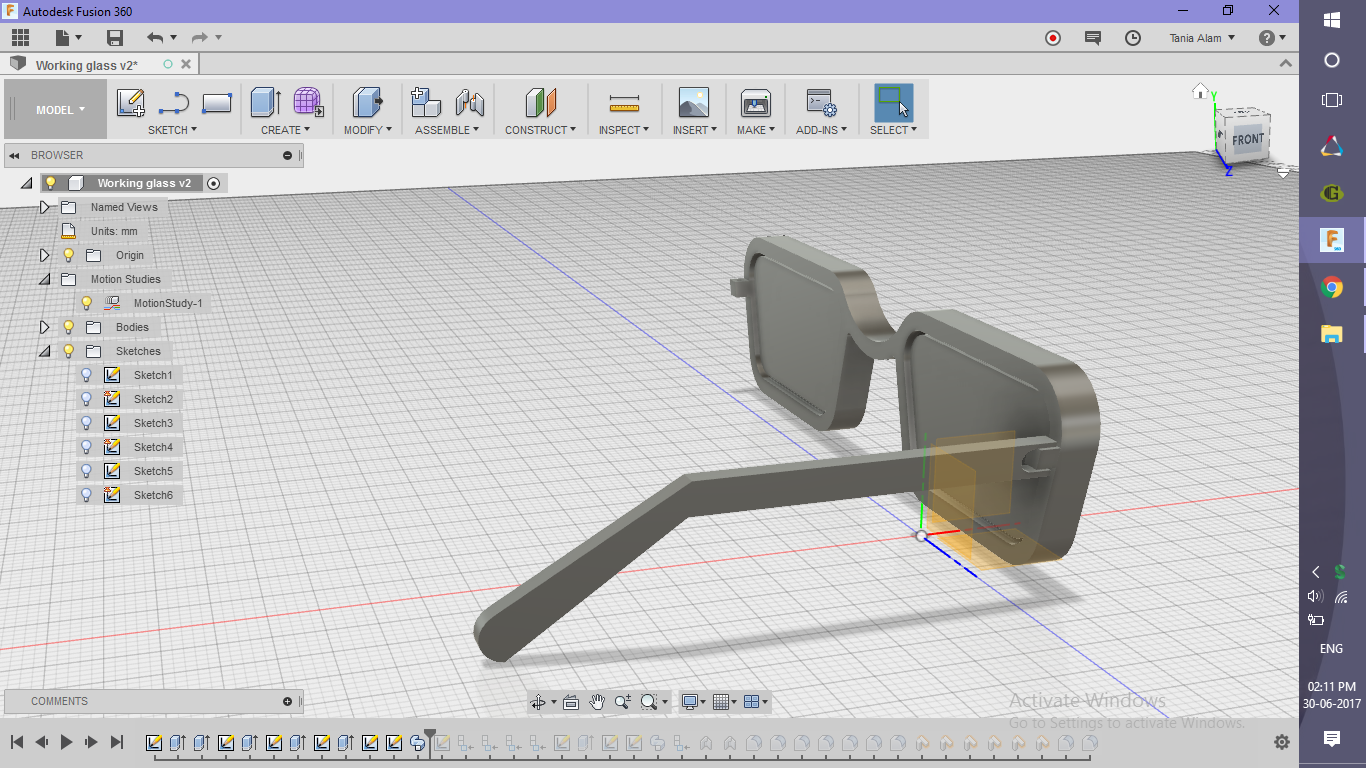
- Create a sketch choosing the top surface of the connector as the sketch plane
- Draw a line parallel to the side as shown (can be any random line but in the proper direction)
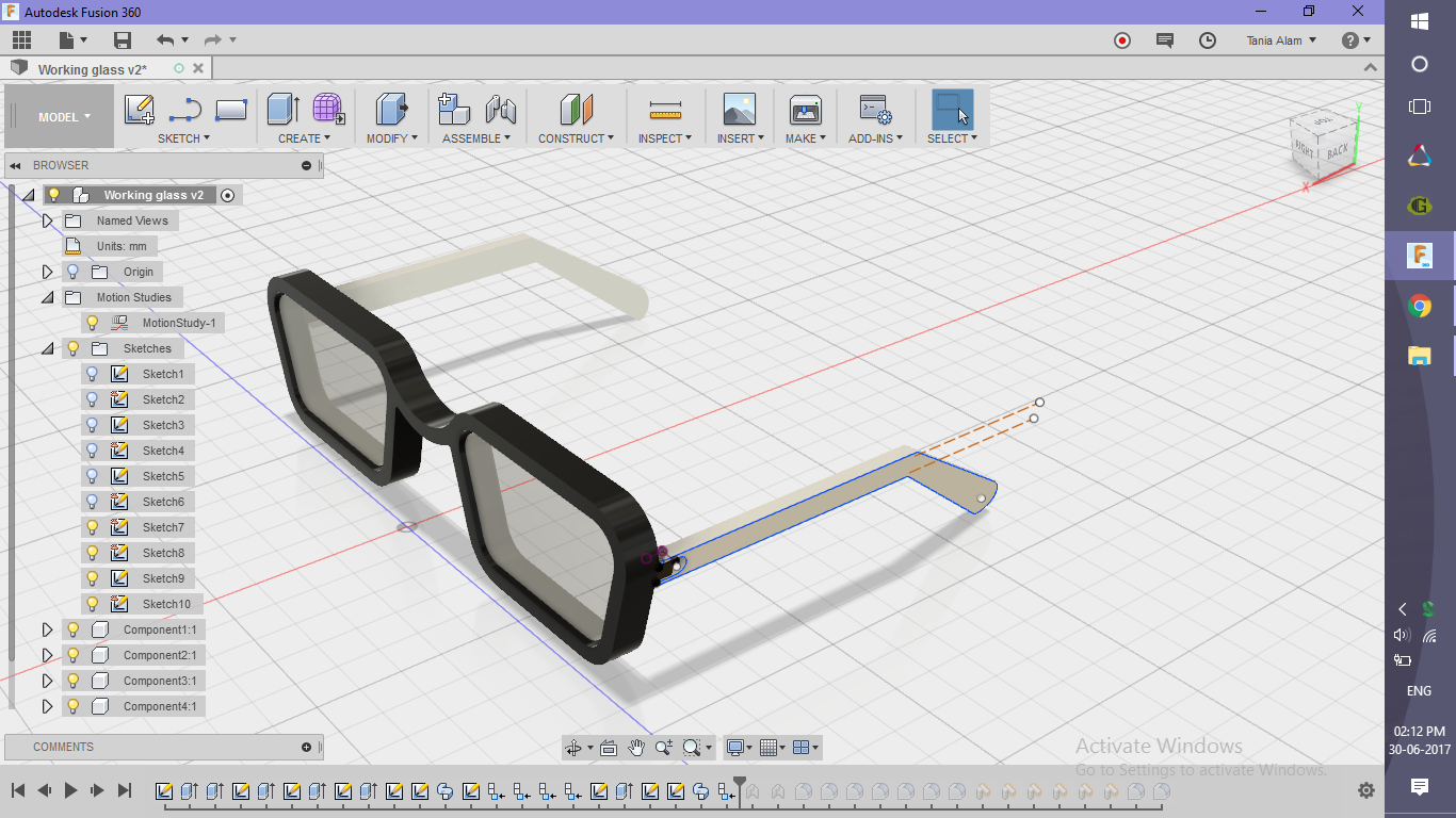
- Use "Sweep" command to extrude the sketch through this path
Consideration:
If you simply extrude it, it would intersect the body as the plane of the frame is not horizontal.
Add Some Finishing
.png)
.png)
.png)
.png)
.png)
.png)
.png)
.png)
.png)
.png)
.png)
.png)
.png)
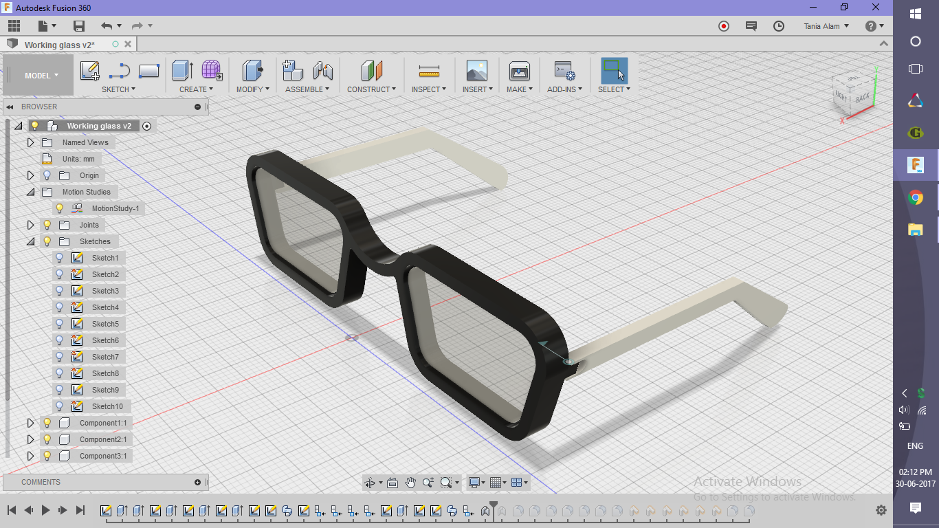
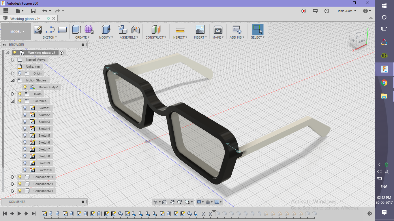
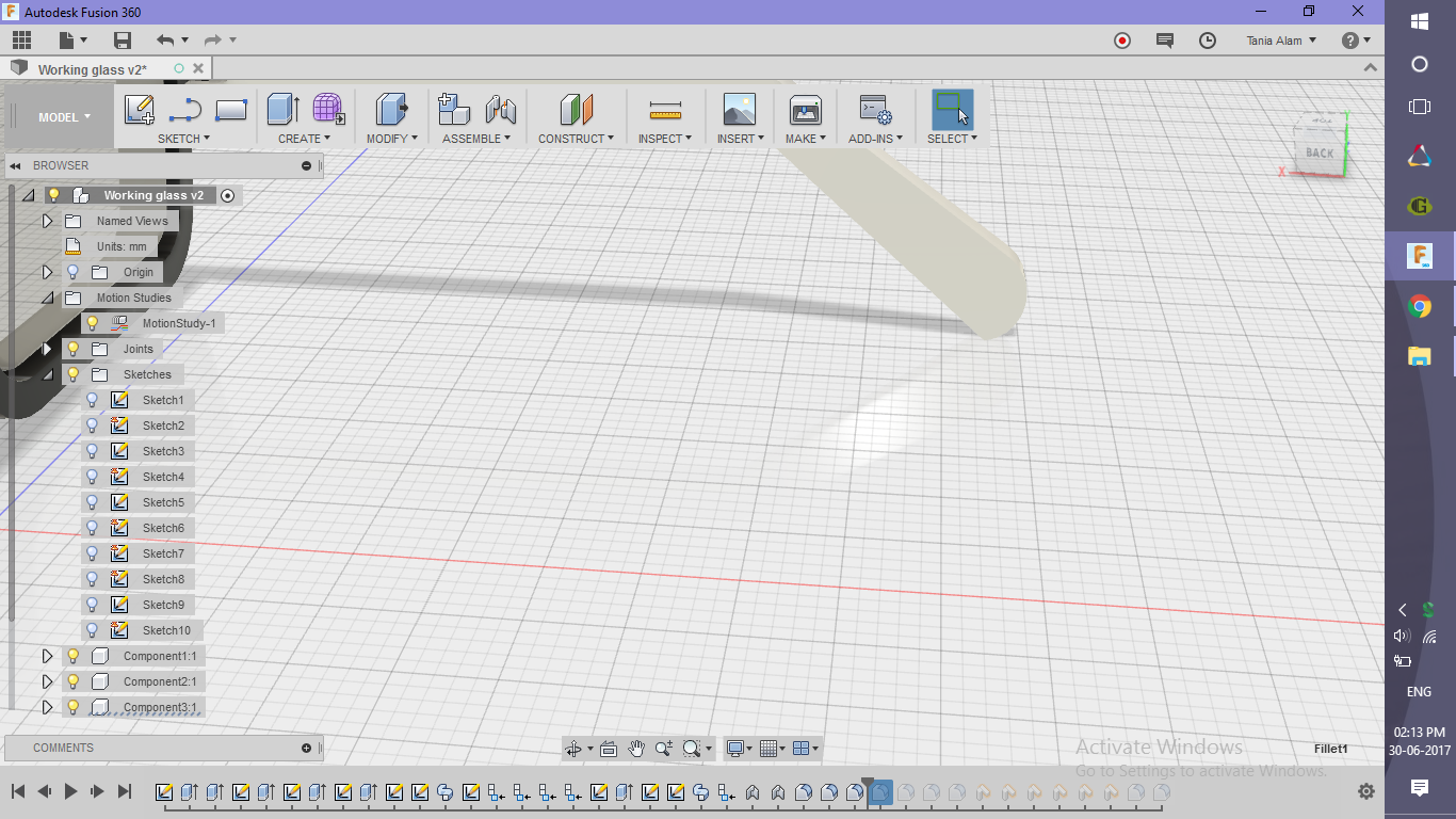
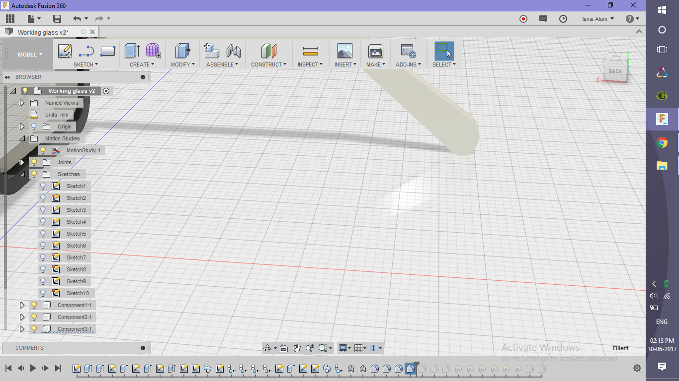
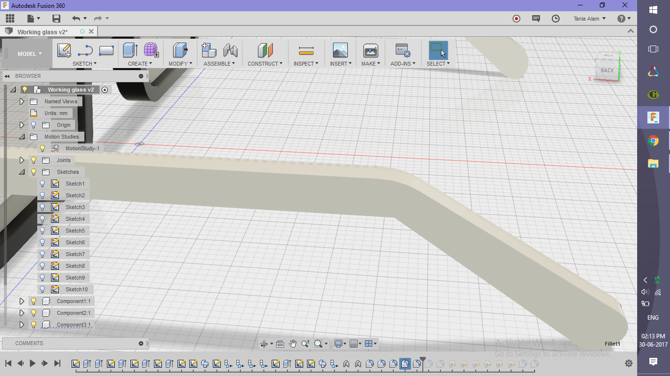
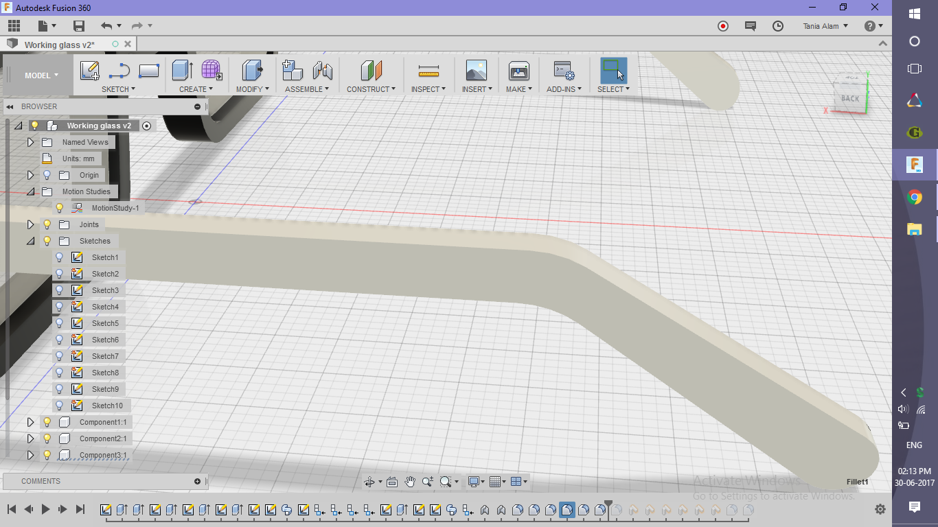
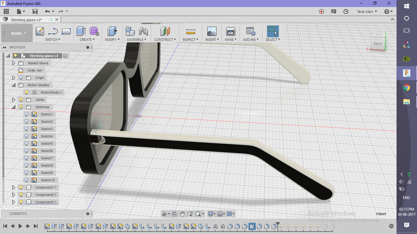
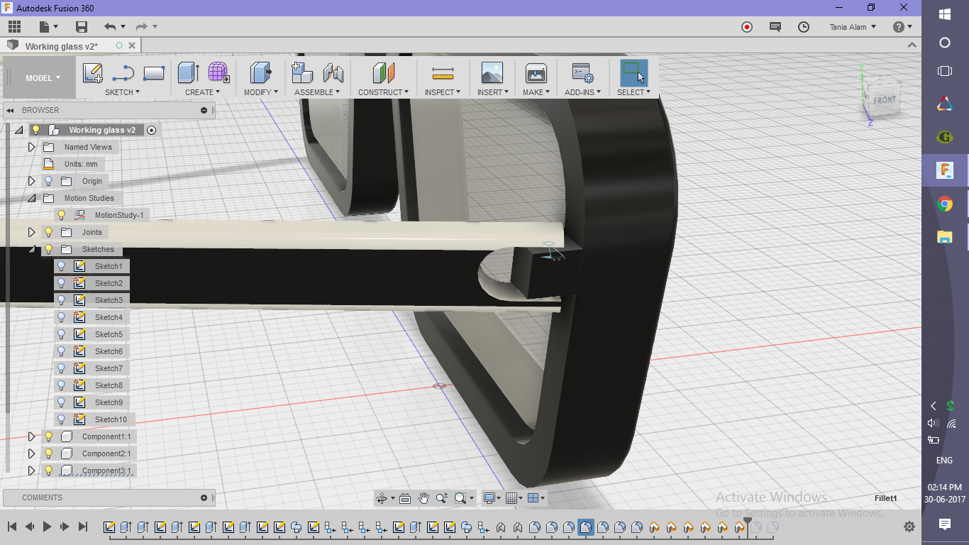
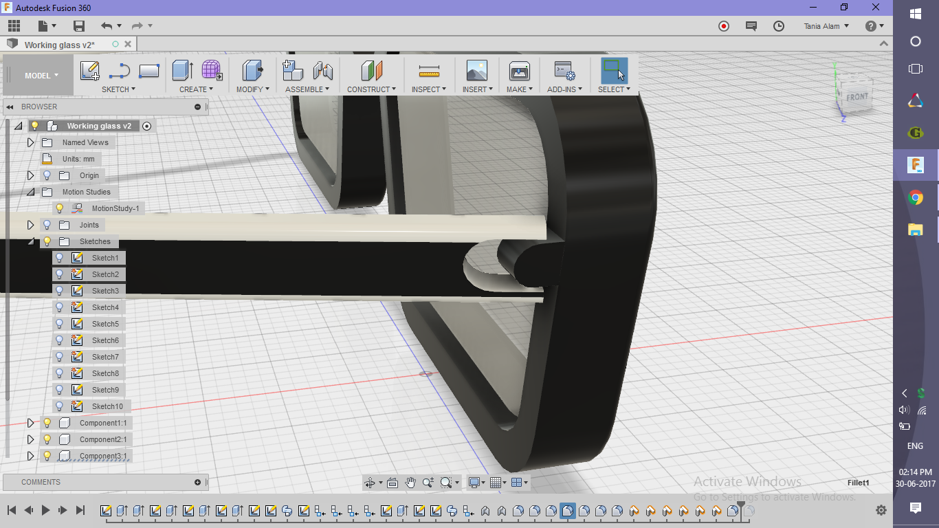
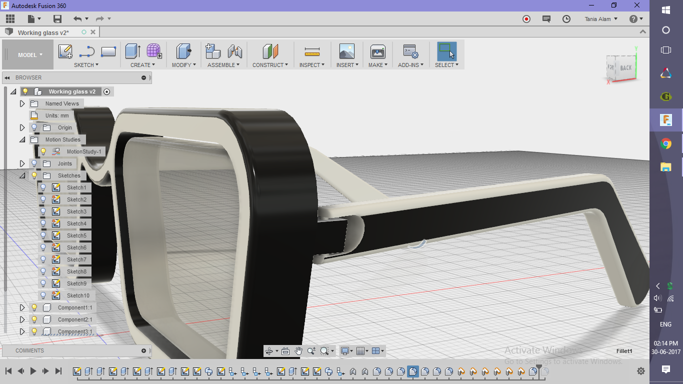
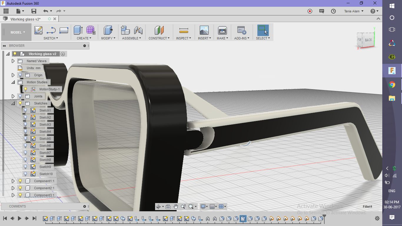
- Add some fillets and remove all sharp edges as shown
- Add Physical Materials
- "Glass" for glasses
- "Plastic" for the frame
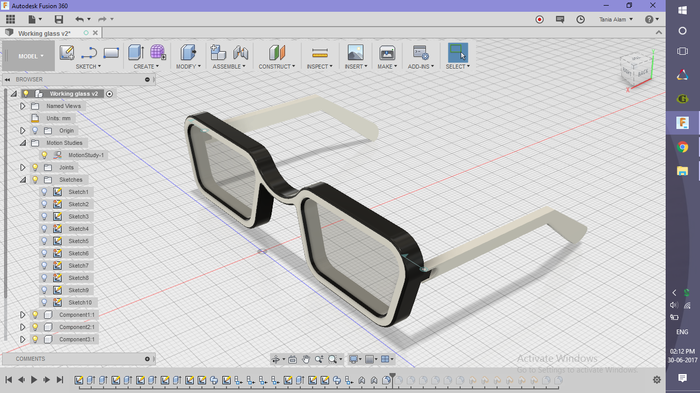
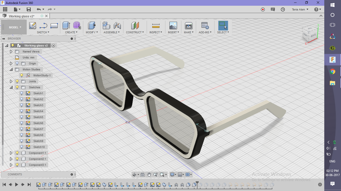
- Apply Appearances to the bodies and faces
- Apply "Black" colored Plastic to the frame (Choose "Bodies" option)
- Apply "White" colored Plastic to the hands of the frame
- Apply "Black" one to the side of the hand (Choose "Faces" option)
- Apply "White" one to the front face of the frame
I did that color mismatch to give it a trendy look but you can use your own color combination.
Make It Work!
.png)
.png)
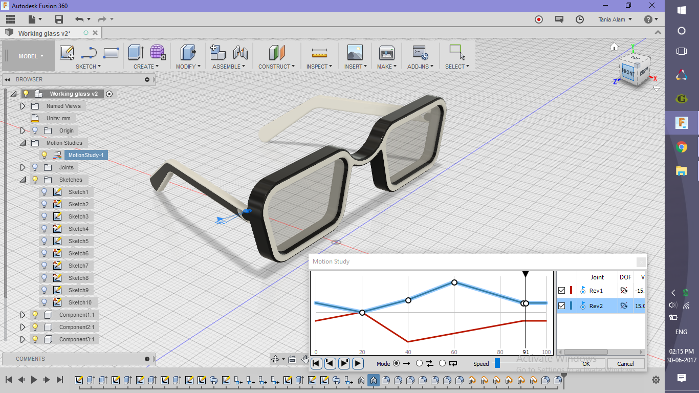
Before you add any kind of joints you need to convert the bodies into components first. Right click on the name of the body in the browser and choose "Create components from bodies".
- Add joints between the components
- Go to "Assemble" tab
- Click on "As-built" command
- Choose the two components
- Choose the "Revolute" option
- Pick up a location for the joint (choose the central rod)
- Repeat the same steps for the other hand too
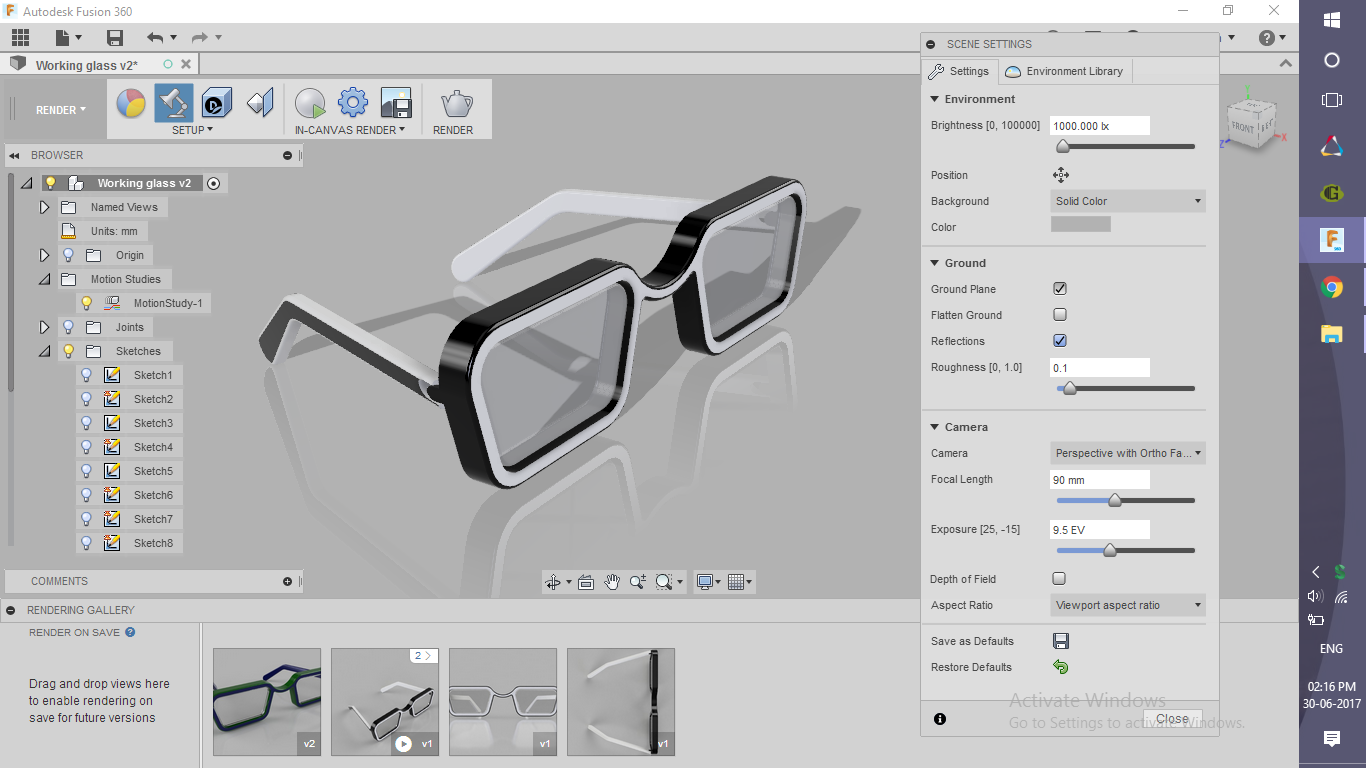
- Create a motion study
- Go to "Assemble" tab
- Click on "Motion Study" option
- Drag the slider to choose steps (I choose 90)
- Add points by clicking on the line
- Choose non-uniform and randomly varying angles for each step
Considerations:
While choosing the components to assemble, click on the hand first and then on the frame. Else the frame would start rotating instead of the hand.
Get the Renderings!
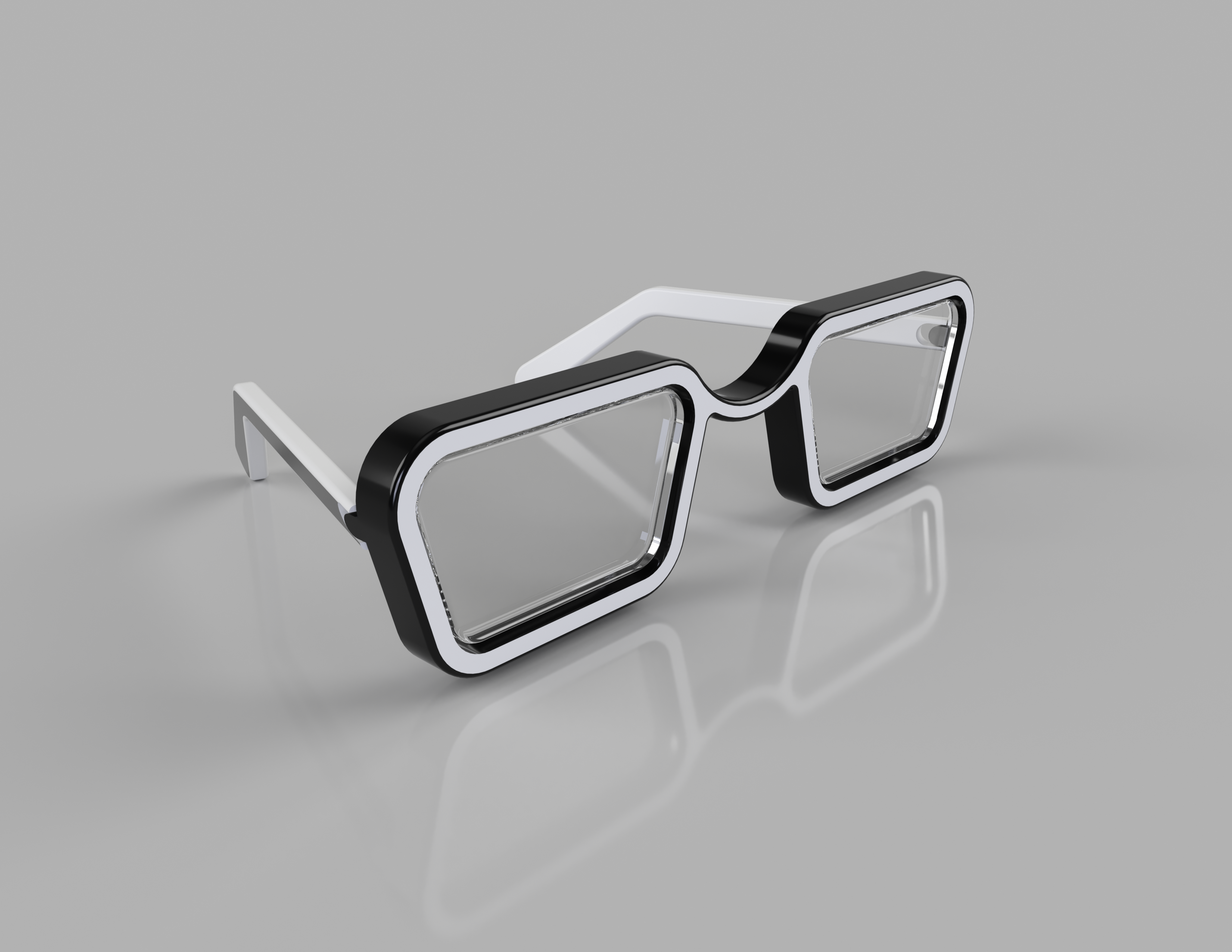
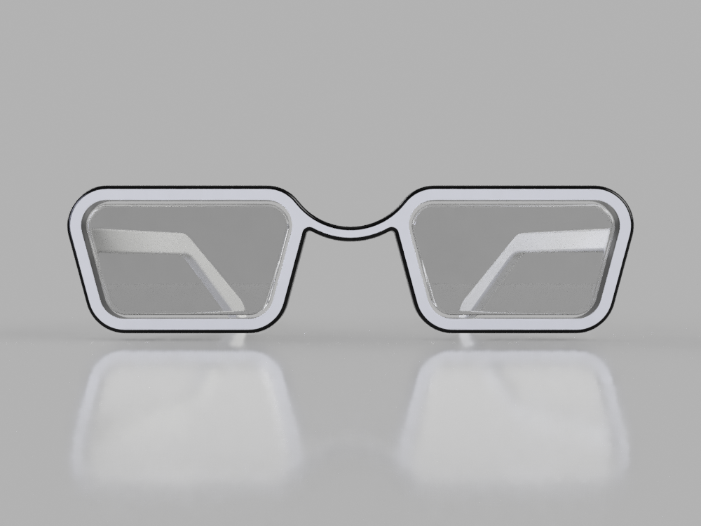
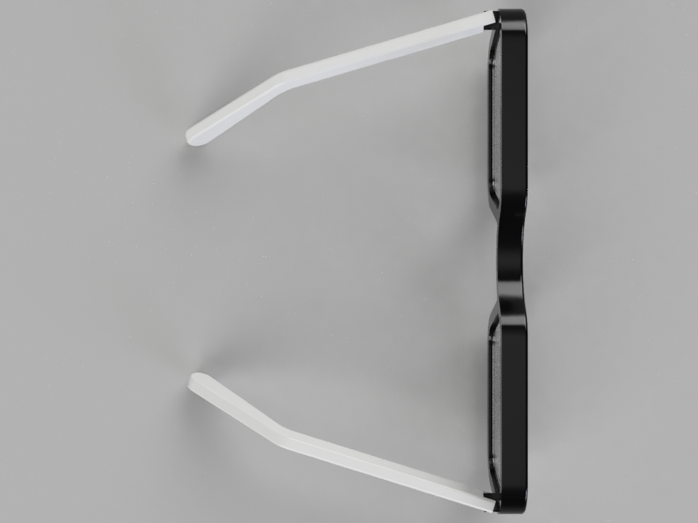
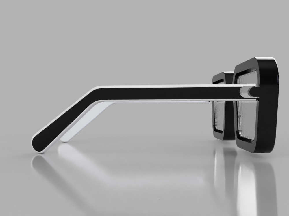
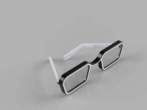
Once you save the file, rendering will start automatically. If you have created the motion study, choose a view and render it as the motion study. I've attached a file of the motion study I created.
Please share your rendering here using the "I Made It" button. I'm eager to see those!
Apply Some Advanced Settings (optional)
.png)
.png)
.png)
.png)
.png)
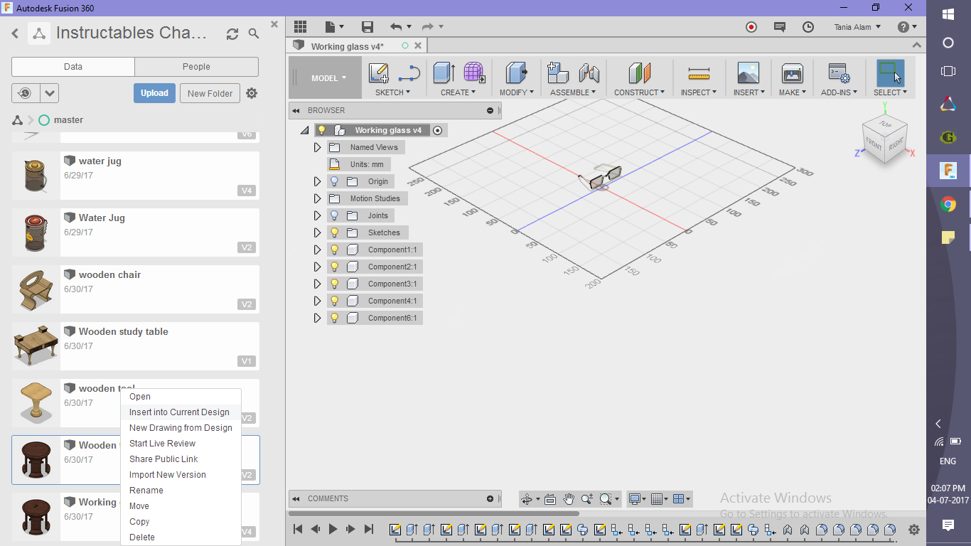
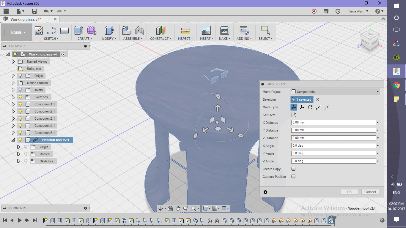
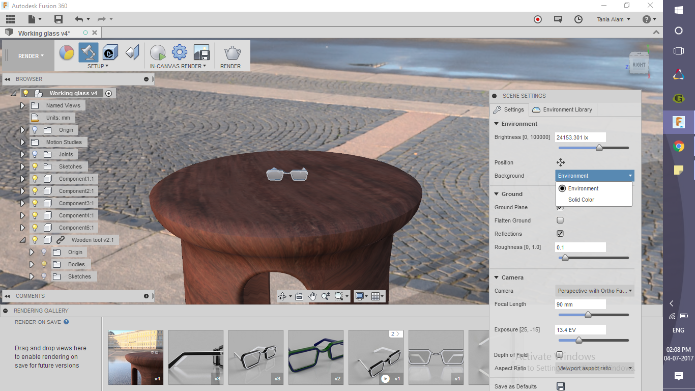
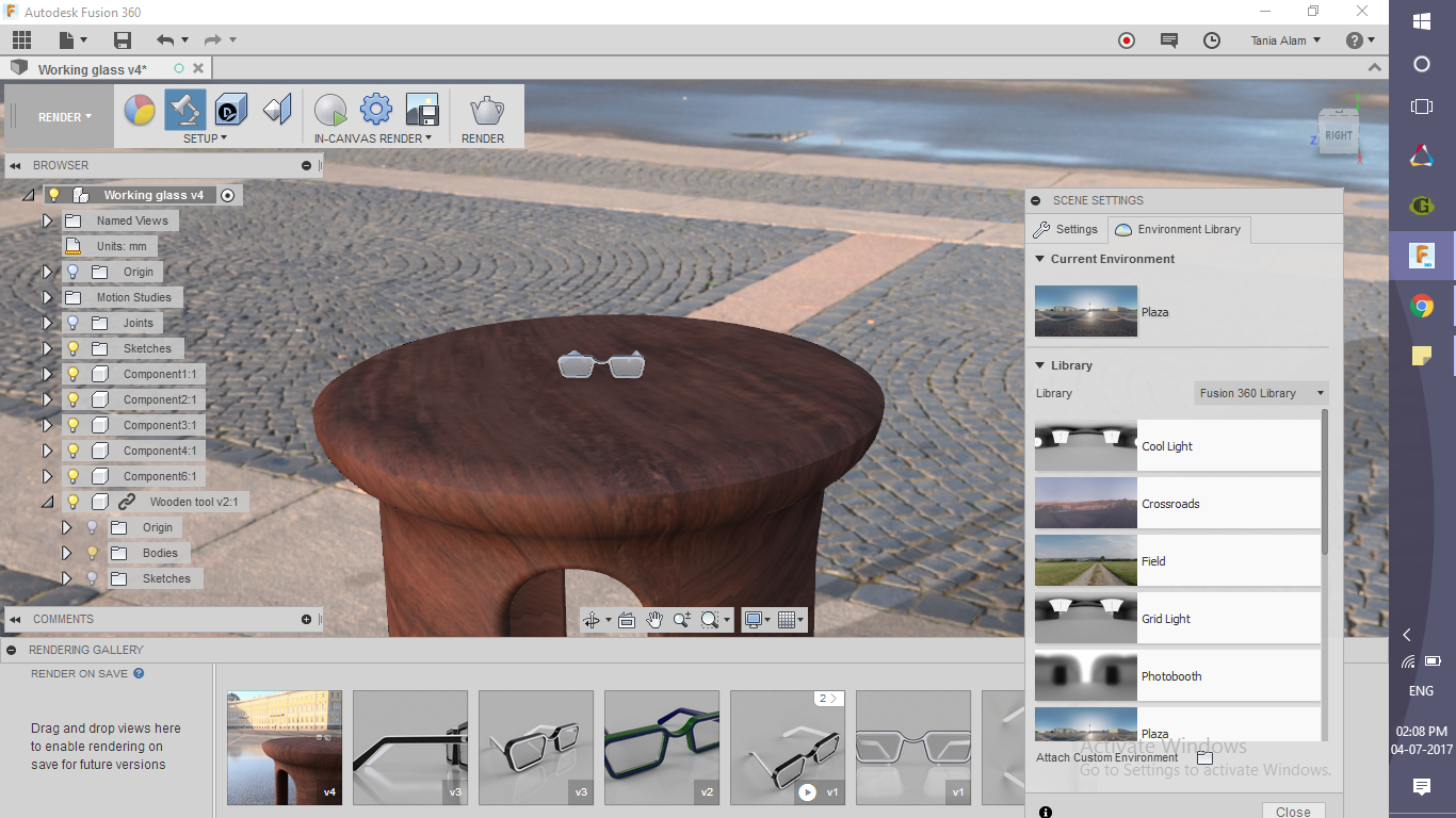
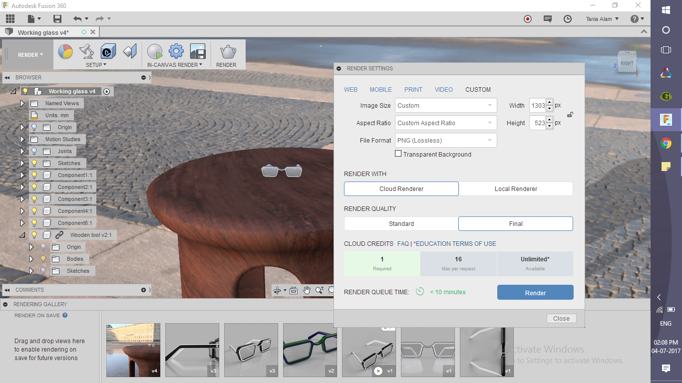
This step is for those who have made this tool using my tutorial. If you already have some models of tables, you can use them too. These are the steps you need to follow to get a similar rendering.
- Find the file of the tool in Fusion, right click and choose "Insert into current design"
- Position it accordingly with the box
- Go to Scene settings and Choose "Environment" option (I've used "Plaza")
- Go to the rendering workspace and click on the "render" option!