Mad Max: Respiratory Racer

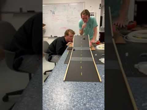
This project creates a simple way to race two toy cars along a handmade racetrack, controlling the speed of the cars using the strength of each racer's breath. Pressure sensors will output a voltage based on how hard the racer blows into tubing, which will then be relayed to an Arduino Uno. The Arduino will then map this digitized voltage into a PWM signal that is sent to the motor driver. This outputs a change in speed that is relayed to the motor based on the pressure input. The changing speed of the motors will reel in a fishing line that is attached to toy cars, allowing them to race in real time!
Supplies
1 Arduino Uno
1 Breadboard
1 Arduino to USB Connection Cable
4 Alligator Jumper Wires
14 Male-to-Male Jumper Wires
6 Male-to-Female Jumper Wires
1 9V Battery with + and - Snaps
2 480-6252-ND Pressure Sensors
2 DC Motors
1 L298N Motor Driver
Wooden Dowels
Tygon f-4040-a Tubing
2 Toy Cars
Fishing Wire
2 Small Pulleys (optional)
Cardboard
Hot Glue
Construct the Ramp
.jpeg)
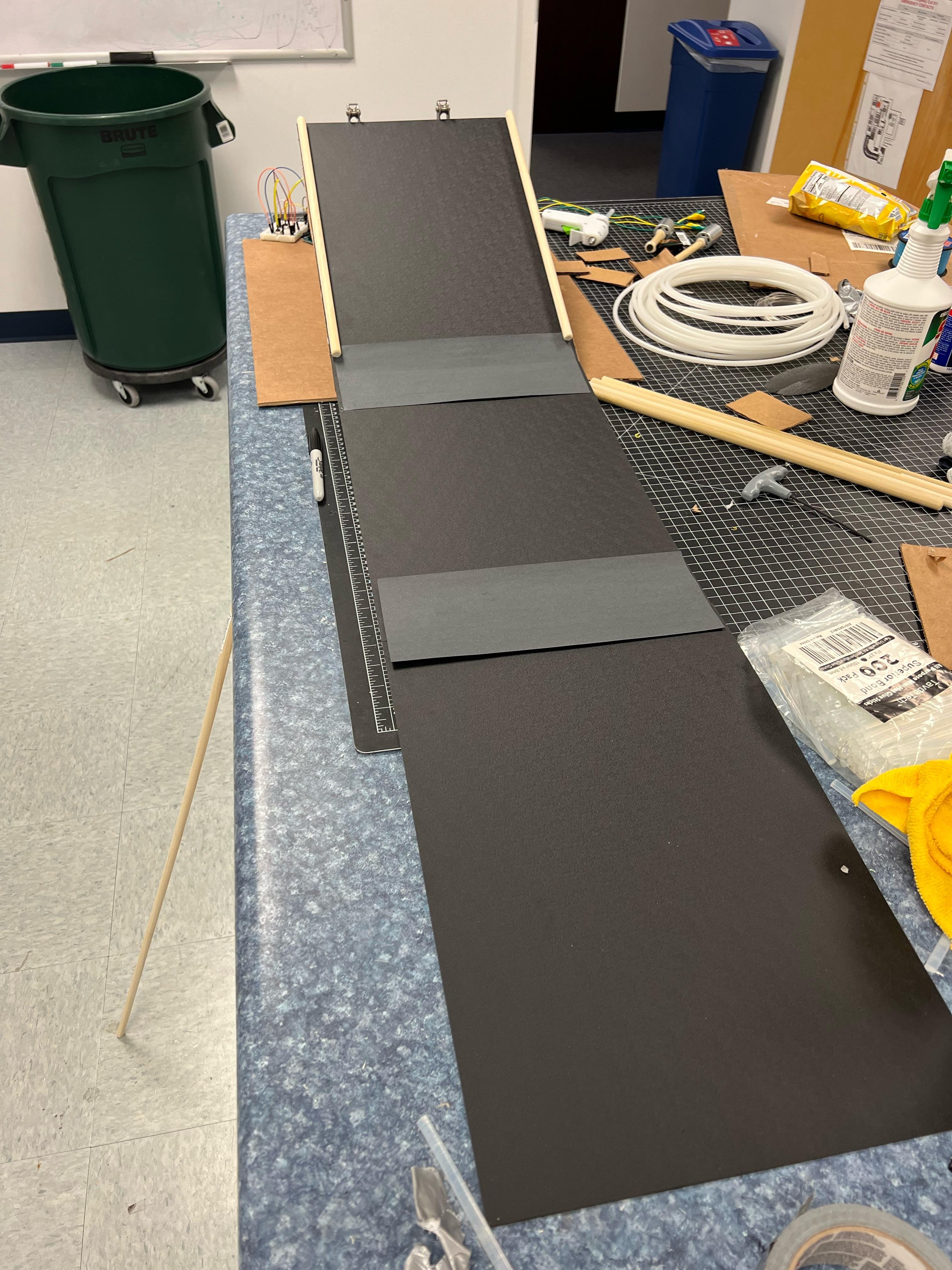
1. Create a track and ramp (optional) out of the cardboard and hot glue for the cars to race along.
2. Make carboard housings for the motors to sit in so they don't move during the race.
3. If there is a ramp, the underneath can serve as a garage for your toy cars and electronics.
4. If there is a ramp, attach the pulleys to the top of the ramp for the fishing line to run along.
5. Add wooden dowels to the sides of the ramp as guard rails for the cars.
6. Some pieces of the tubing can be glued to the center of the ramp to imitate road paint.
Connect the Pressure Sensor to the Arduino
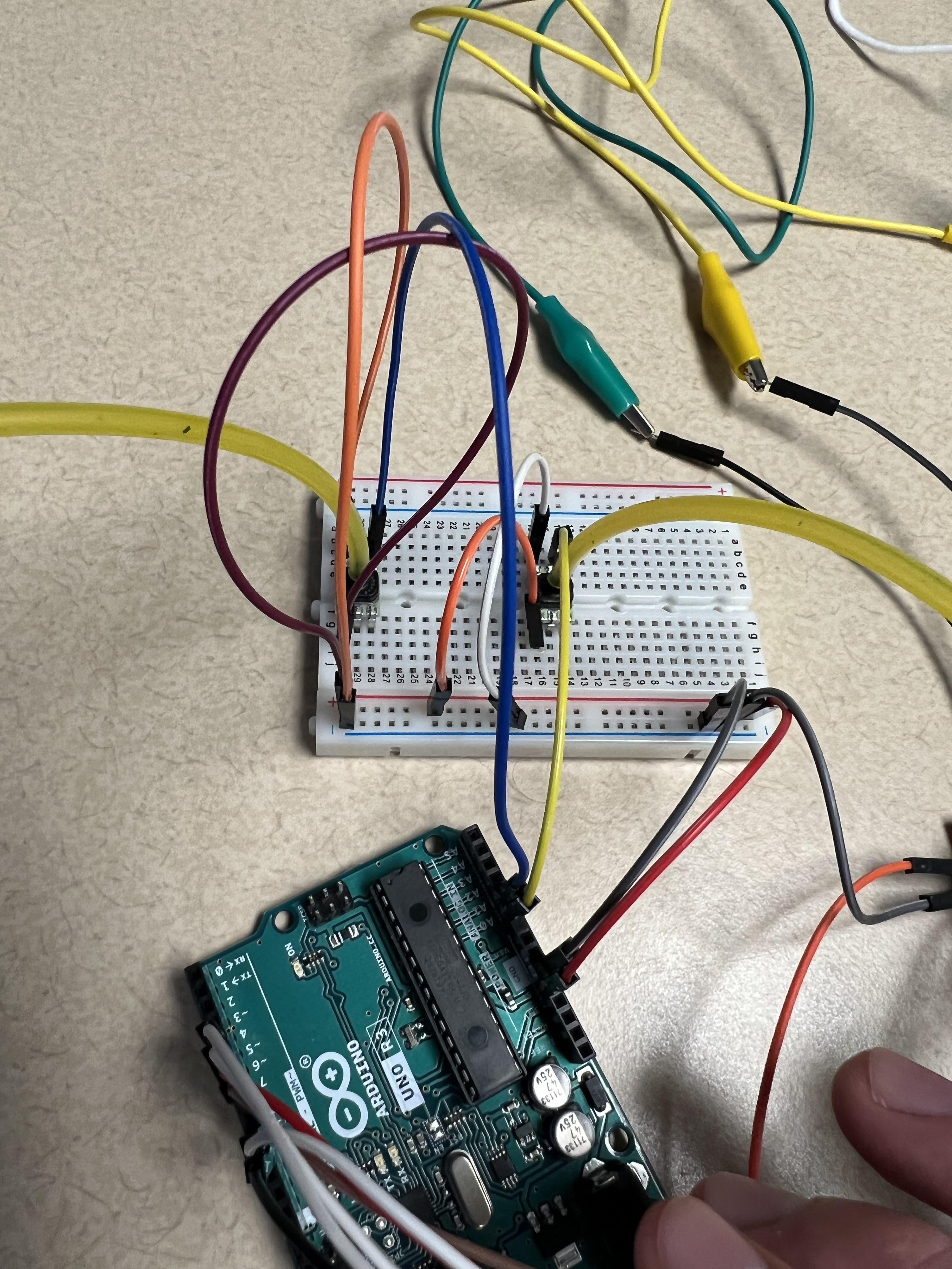
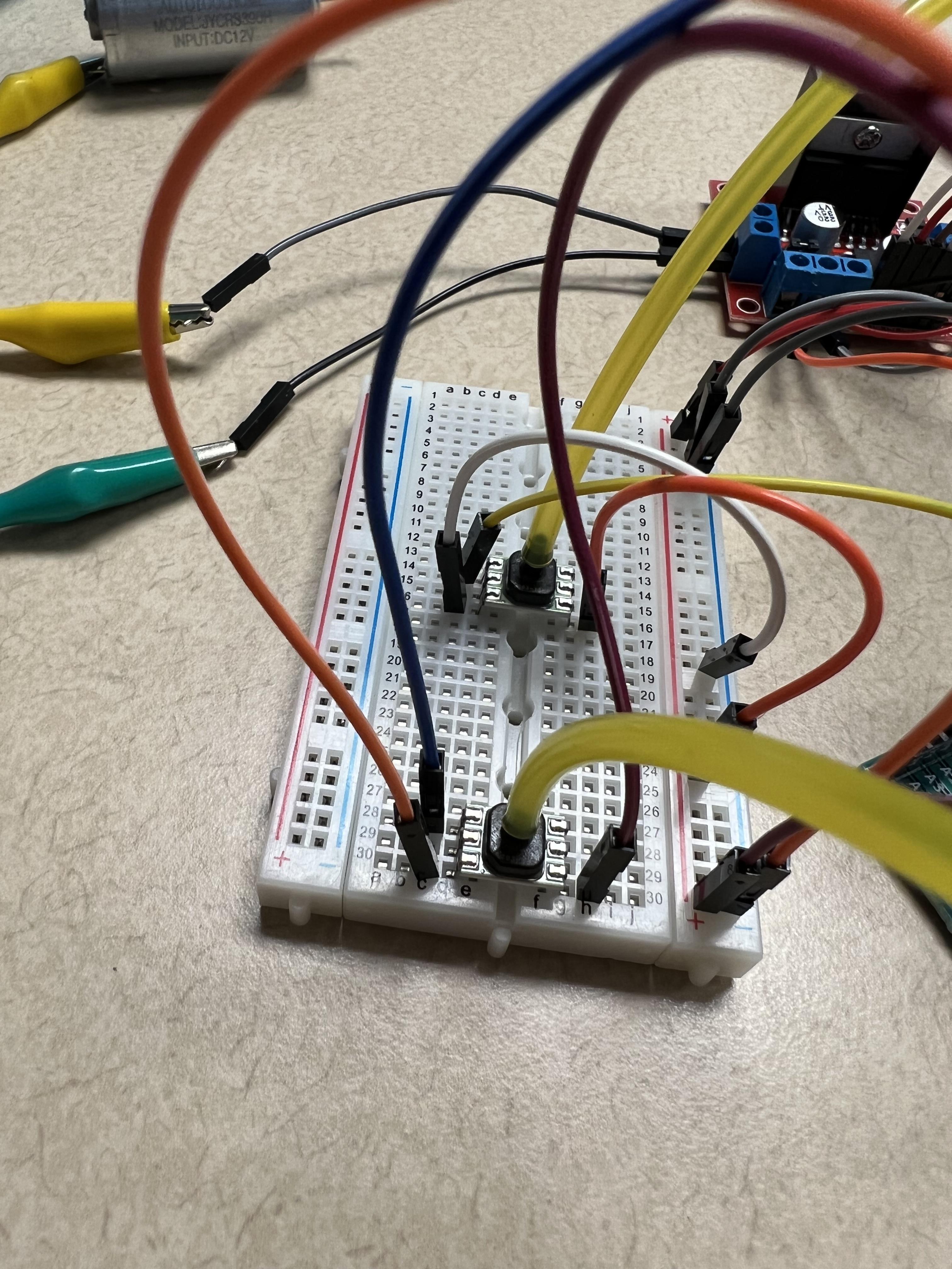
1. Connect the 5V Power pin of the Arduino Uno into the positive rail on the breadboard and the ground pin to the negative rail.
2. Plug your two pressure sensors into the breadboard.
3. Connect the ground pin of a sensor (Pin 1) into the negative rail and the positive supply pin (Pin 6) to the positive rail.
4. Connect the output voltage pin (Pin 3) to the A0 port on the Arduino Uno.
5. Repeat steps 3 and 4 for the other sensor, using the A1 pin instead of the A0 pin for step 4.
Connect the Motors to the Arduino
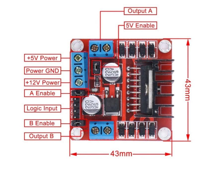
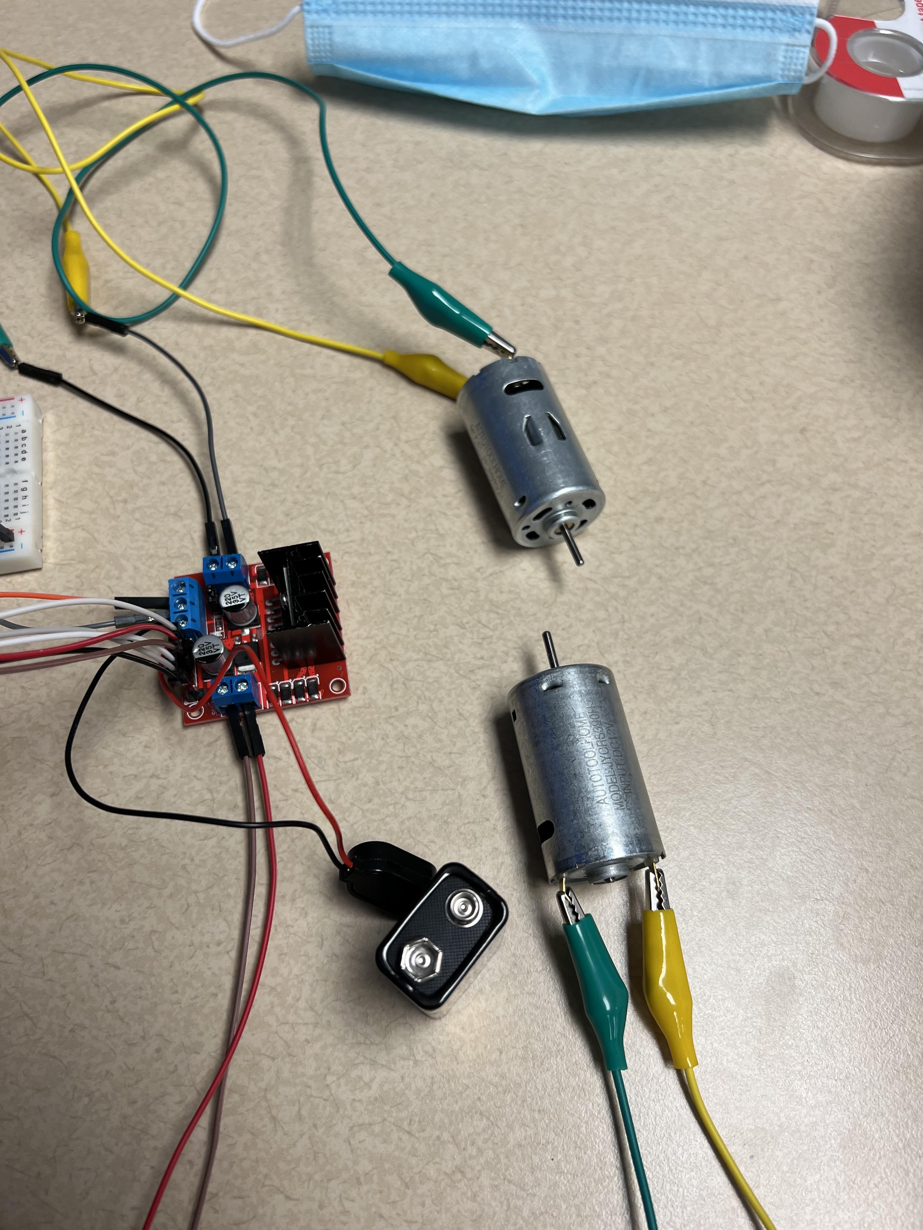
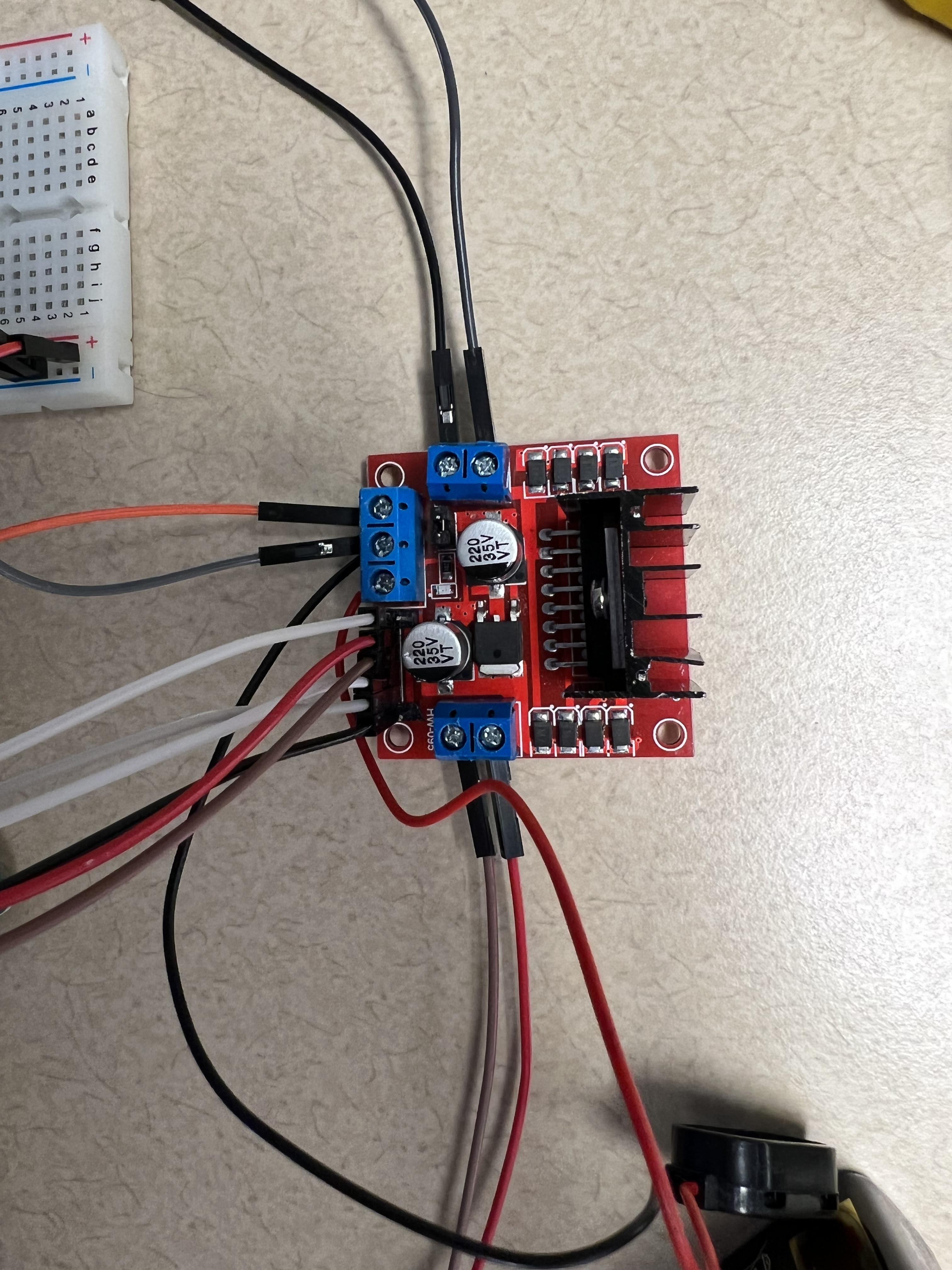
1. Remove the plastic pieces from "5V Enable", "A Enable", and "B Enable" in the figure. This removes the motor driver's onboard linear regulator so that the Arduino's can be used and allows for the motor's speed to be modulated.
2. Connect the 9V battery's positive lead to the port labeled "+12V Power" in the L296N figure and the battery's negative lead to the port labeled "Power GND". This is the supply power for the motors (the screws on the motor driver board can be loosened and tightened to secure the jumpers).
3. From the breadboard, use a jumper to connect the negative ground rail to "Power GND" and another jumper to connect the positive rail to "+5V Power". This gives the motor driver a reference of 0-5V that it will be receiving from the Arduino Uno.
4. Using the female-to-male jumpers, connect the pins as follows - the A Enable pin in line with the other 5 to Arduino Pin 9, IN1 to Pin 6, IN2 to Pin 7, IN3 to Pin 5, IN4 to Pin 4, and the B Enable pin in line with the other 5 to Pin 10. These can be changed at your discretion so long as they are similarly changed in the code and the Enable Pins are still connected to a PWM Pin on the Arduino. This is so that the motor speed can be regulated.
5. Connect jumper wires to all 4 Output Pins on the motor driver. These will supply regulated power to the motors.
6. Connect alligator clips from the jumper wires to the motor terminals. The direction to motor spins will change depending on which pin is connected to which terminal (and also depending on which IN pins are set to LOW/HIGH).
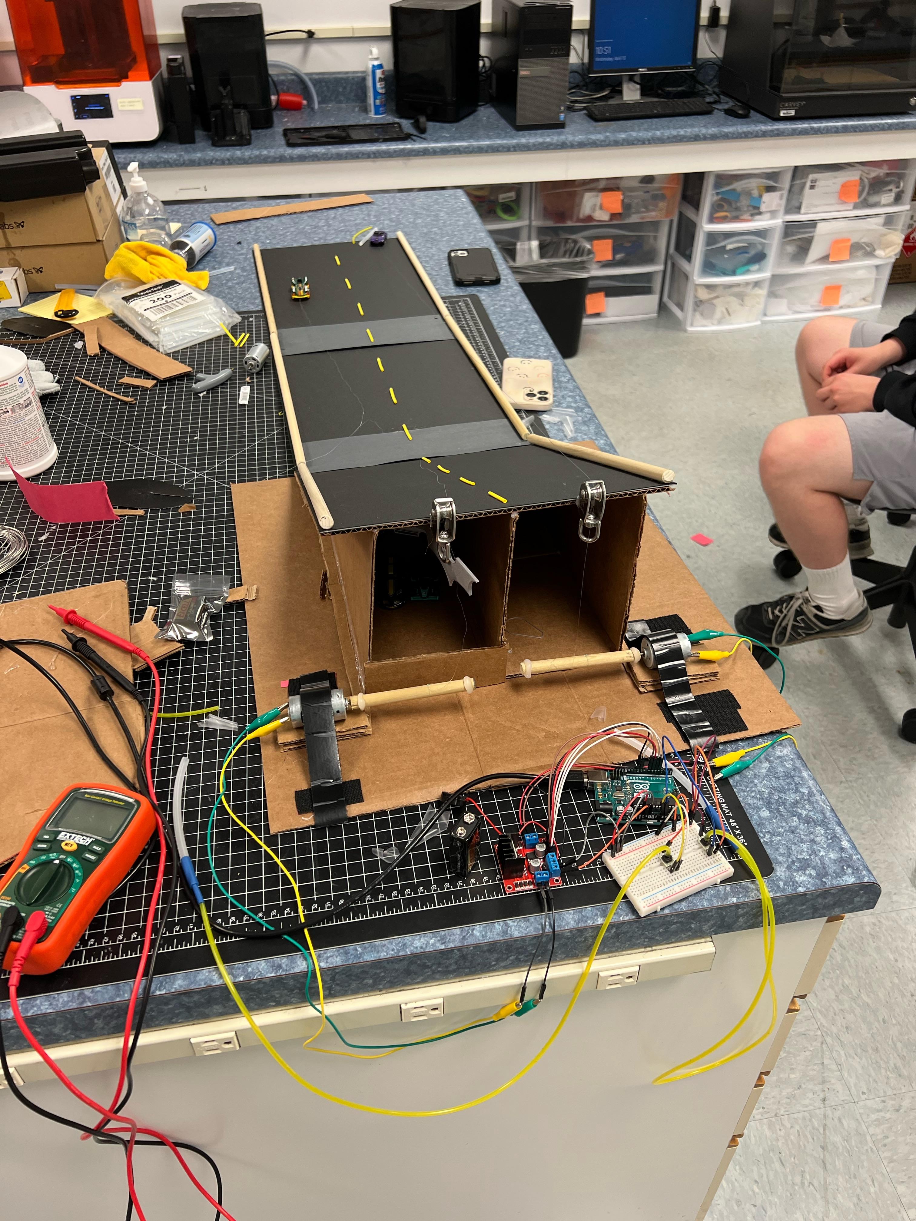
Final Setup
.jpeg)
1. Connect lengths of tubing of a length that allows a person to comfortably blow into it to the pressure sensor input on its top.
2. Drill holes into the wooden dowels and connect them to the spinning ends of the motors.
3. Optionally, make guides for the wooden dowels so that the fishing line can stay contained while it is being reeled in.
4. Glue one end of fishing line to the wooden dowels so that it can be reeled in. Tie the other end of the fishing line around the toy car (or connect them in a similar manner). If you have a ramp on your race track, make sure to thread the line through the pulleys.
5. Calibrate the mapping in your code so that when you run the code, the car doesn't move when you aren't breathing into the tube and goes the speed you want when blowing at max pressure.
6. Upload your code to the Arduino Uno and optionally open the serial monitor to see the input's graph.
7. Set your electronics in a convenient place where the motors can be inside of their housings to stay in place and the racers can blow into the tubing.
8. Connect the 9V battery to its snaps and get ready to race!
9. Have someone count down to begin the race and have the racers blow into the tubes at the same time.
10. Watch the cars race each other along your track!
The Code (Arduino IDE)
// constants won't change
const int ENA_PIN = 9; // the Arduino pin connected to the EN1 pin L298N
const int IN1_PIN = 6; // the Arduino pin connected to the IN1 pin L298N
const int IN2_PIN = 7; // the Arduino pin connected to the IN2 pin L298N
const int ENB_PIN = 10; // the Arduino pin connected to the EN2 pin L298N
const int IN3_PIN = 5; // the Arduino pin connected to the IN3 pin L298N
const int IN4_PIN = 4; // the Arduino pin connected to the IN4 pin L298N
const int MA_IN = A0; // Arduino pin reading motor A's breath input
const int MB_IN = A1; // Arduino pin reading motor A's breath input
// the setup function runs once when you press reset or power the board
void setup() {
// initialize digital pins as outputs and inputs
Serial.begin(9600);
pinMode(ENA_PIN, OUTPUT);
pinMode(IN1_PIN, OUTPUT);
pinMode(IN2_PIN, OUTPUT);
pinMode(ENB_PIN, OUTPUT);
pinMode(IN3_PIN, OUTPUT);
pinMode(IN4_PIN, OUTPUT);
pinMode(MA_IN,INPUT);
pinMode(MB_IN,INPUT);
// give the motors a high and low reference, can swap HIGH and LOW to reverse spin direction. Setting both 1 and 2 or 3 and 4 to the same value will stop the motor.
digitalWrite(IN1_PIN, LOW);
digitalWrite(IN2_PIN, HIGH);
digitalWrite(IN3_PIN, LOW);
digitalWrite(IN4_PIN, HIGH);
}
// the loop function runs over and over again forever
void loop() {
int MotA = analogRead(MA_IN); //reads voltage output from sensor A
int MotB = analogRead(MB_IN); //reads voltage output from sensor B
Serial.println(MotA); //this allows us to read our ADC that we are getting from Motor A as a check
int pwmAOutput = map(MotA, 0, 1023, 0 , 255); //this should be changed to match the ADC ranges that you get and to change motor speed as desired, currently they show ADC and speed ranges, respectively
int pwmBOutput = map(MotB, 0, 1023, 0 , 255); //these ranges should be identical to the above for a fair race
analogWrite(ENA_PIN, pwmAOutput); //writes speed to motor A
analogWrite(ENB_PIN, pwmBOutput); //writes speed to motor B
}