MSP430 Based Chronulator (using Launchpad Chip)
by paradug in Circuits > Clocks
33809 Views, 56 Favorites, 0 Comments
MSP430 Based Chronulator (using Launchpad Chip)
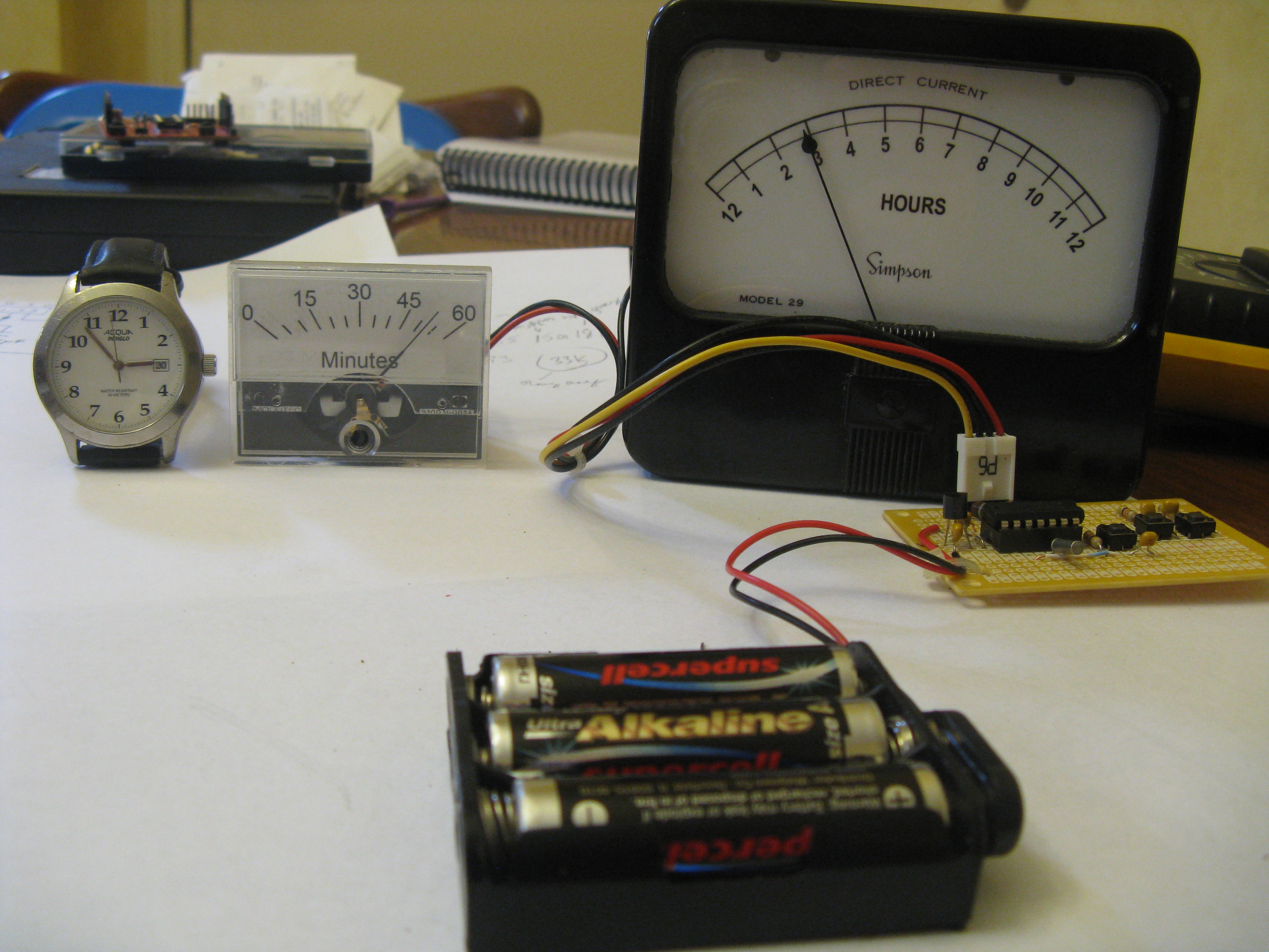
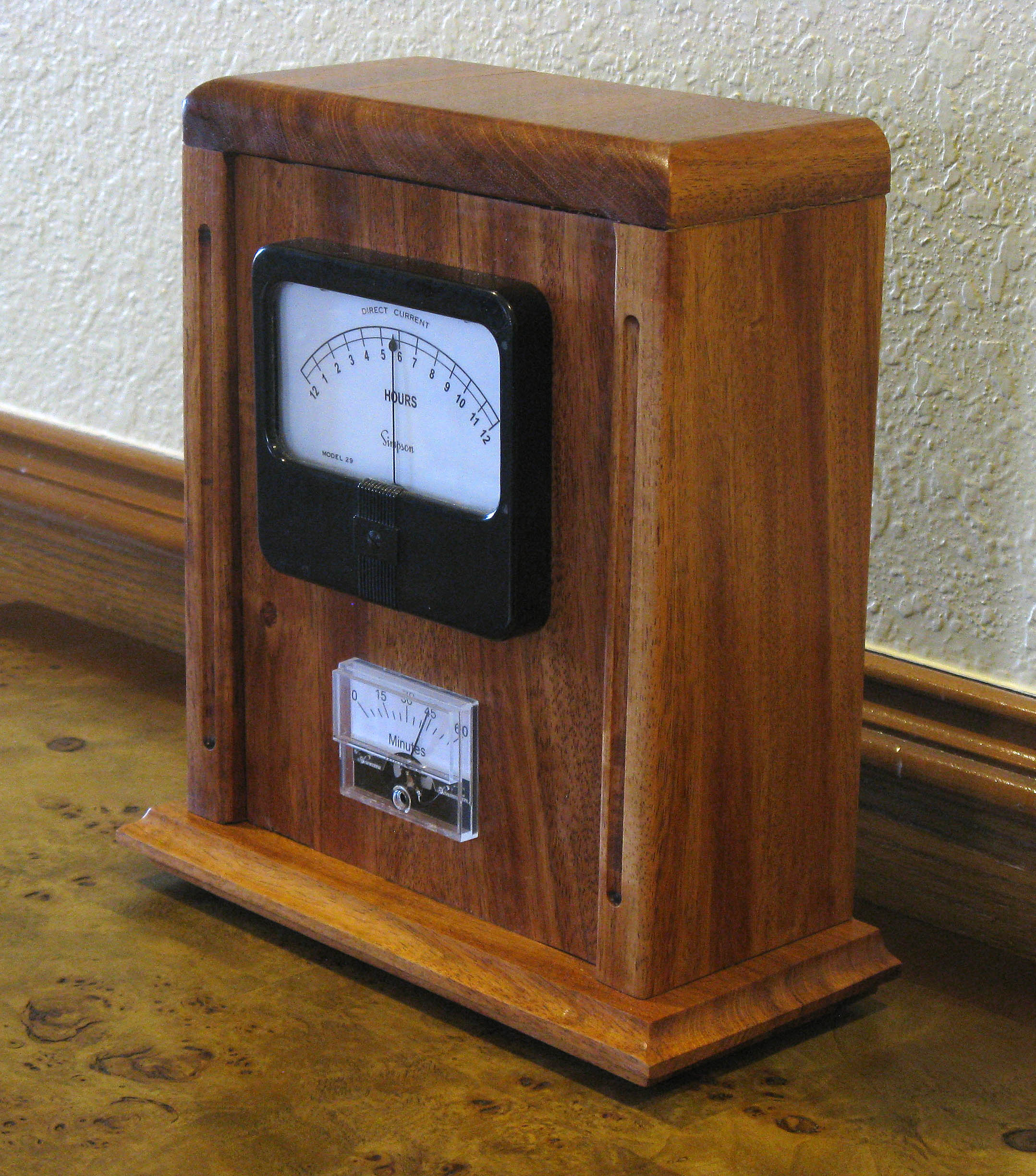
I decided as a learning experience to use the MSP430G2211 from the Launchpad kit to build a Chronulator. It turns out that this is a really fun project, and yes, I learned a lot!
See the plans for the mantel clock case that I built for this Chronulator.
What You Need - Materials / Tools
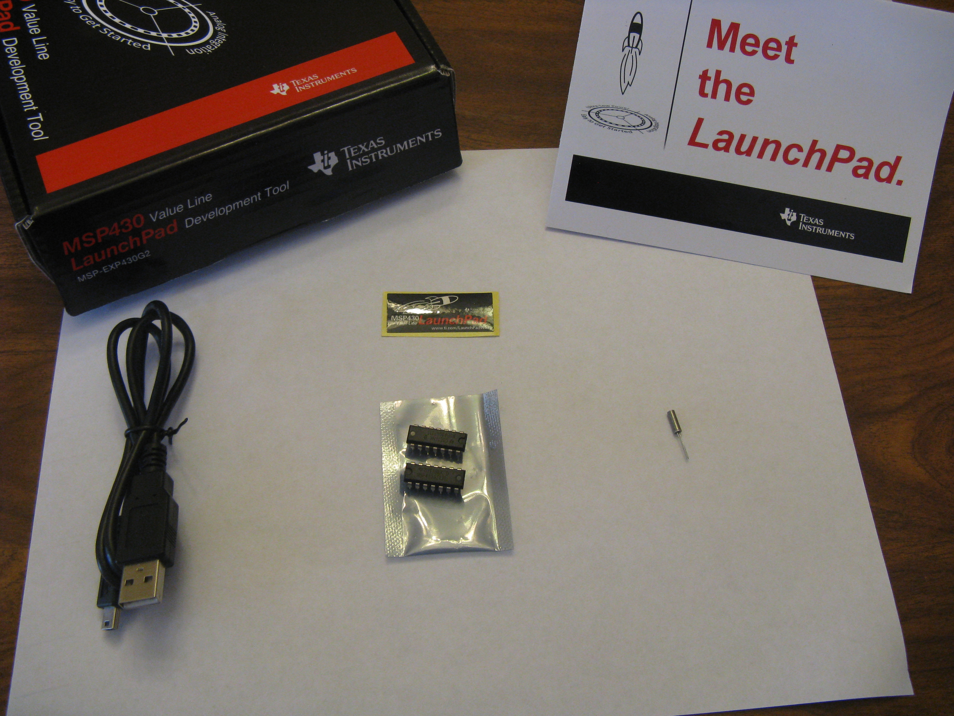
The details on how to get a Launchpad are at http://processors.wiki.ti.com/index.php/MSP430_LaunchPad_%28MSP-EXP430G2%29?DCMP=launchpad&HQS=Other+OT+launchpadwiki
List of Materials to make Chronulator:
1 - Radio Shack General Purpose Printed Circuit board part # 276-150 (project board)
4 - 0.1uF capacitors
1 - 1nF capacitor
3 - 47k resistors
3 - push buttons
1 - 14 pin DIP socket
2 - panel meters with any combination of full scale values of 50uA, 100uA, or 1mA
note: I'm using a 50uA (mins) and a 100uA (hrs) because that is what I had on hand.
Higher sensitivity meters will result in using less power - longer battery life.
1 - 4 pin male single in-line 0.1 inch header (to connect meters)
1 - 4 pin female single in-line 0.1 inch header with wire
note: I got mine by cutting off a small power connector from an old PC
power supply.
1 - battery holder for 3 AA sized batteries (Radio Shack)
3 - AA batteries
1 - battery leads for 9V size battery (the battery holder required this)
1 - MSP430G2211 (part of Launchpad kit)
1 - watch crystal - 32.768 kHz (One comes with the Launchpad - but I would
suggest keeping that one on the Launchpad and getting another for this project.
I went to Target and bought a watch from their dollar bin and took the
crystal from it. BG Micro sells them for $0.65, but you have to pay shipping.)
1 - LDO, low Iq, 2.5V voltage regulator (I'm using a Seiko S-812-C series regulator
Mouser part # 628-812C25AY-G, Manuf # S-812C25AY-B-G price: $0.51)
The key is to use a LDO regulator with low quiescent current (Iq).
Note: Another alternative is to use 4 AA batteries and a 3.3 V LDO, low Iq,
voltage regulator.
2 - resistors (values depend on meters used - see next step)
Misc:
hookup wire
Tools Required:
Solder gun and solder suitable for working with printed circuit boards
Desoldering tool
Multi-meter (optional, but great in troubleshooting - Harbor Freight price: $3.97)
Screw drivers (for working with panel meters)
needle nose pliers
wire cutter
The Circuit
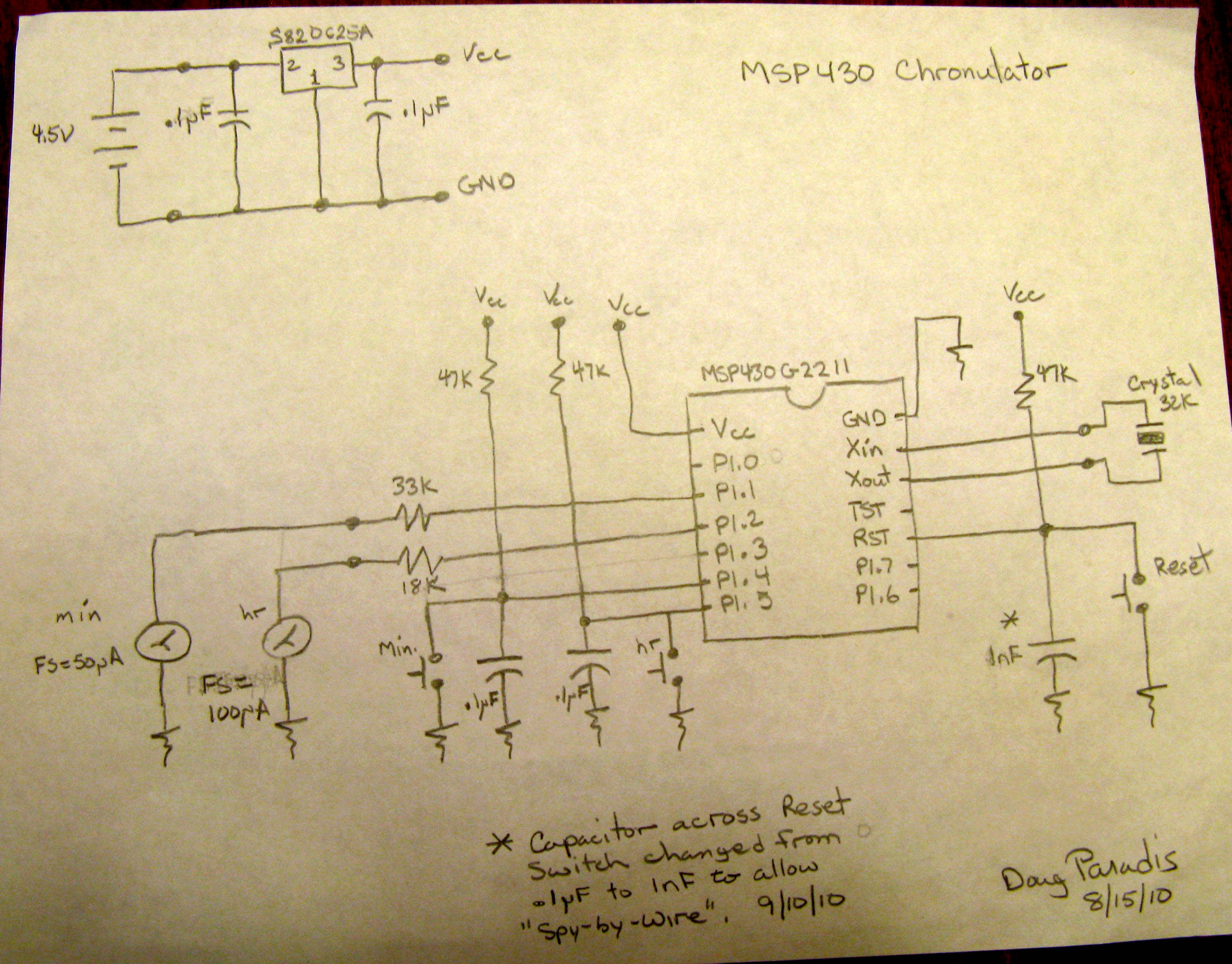
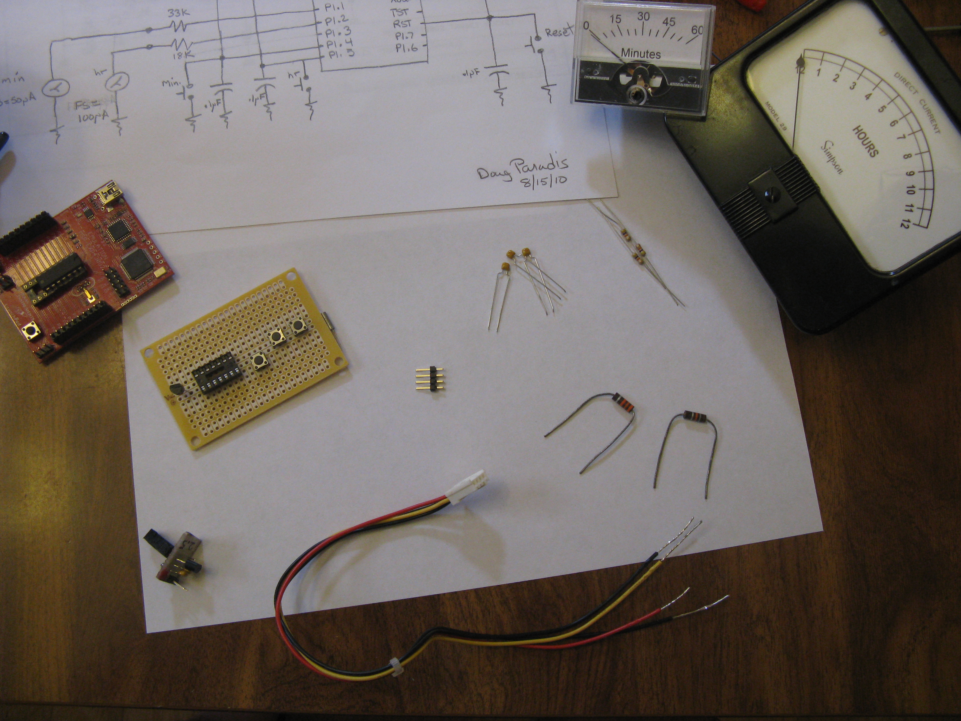
Below is the schematic for the Chronulator. It has 3 push buttons, two of which allow you to adjust the minutes and hours. Pushing the minute or hour buttons will increment the minute or hour values by one. The third button is a reset button. The circuit diagram shows the meter current limiting resistors that I used for my particular meters. I have a 50 uA full scale meter for my minute meter, and a 100 uA full scale meter for my hour meter. The value of the resistor installed between the meter plus terminal and the microcomputer pin depends on the full scale of the meter used.
Here is a table of what resistor you should use based on the meter FS value.
It assumes you are using the 2.5V Vcc that the author originally used.
Resistor mAh used by mAh used by
FS value Hour meter per 12 hrs Minute meter per 12 hrs
--------------------------------------------------------------------------------------------------
50 uA 33k 0.025 0.3
100 uA 18k 0.050 0.6
1 mA 2.2k 0.5 6.0
More sensitive meters are definitely better. If you have to use a FS=1mA meter
use it for your hour meter.
With the 2.5V voltage regulator you should be able to take the batteries down to about 1V and get at least 80% of the batteries' energy (~2000 mAh) without any calibration shifts.
Note: If you are using 4 AA batteries and a 3.3V voltage regulator the results are the same.
If you are using a 3.3V Vcc use these resistor values:
Resistor
FS value
-------------------------------
50 uA 47k
100 uA 22k
1 mA 2.7k
If for some reason later when we calibrate m_cal and h_cal, the sum of the elements of your m_cal array or your h_cal array are not between 8000 and 9500 adjust your resistor value. If the sum of the array is above 9500 reduce the resistor value. If is below 8000, increase the resistor value.
Note: The capacitor that is wired parallel to the Reset button has been changed from 0.1uF to 1nF. This change was made to make "spy-by-wire" work. dp-09/10/10
Using IAR Embedded Workbench KickStart
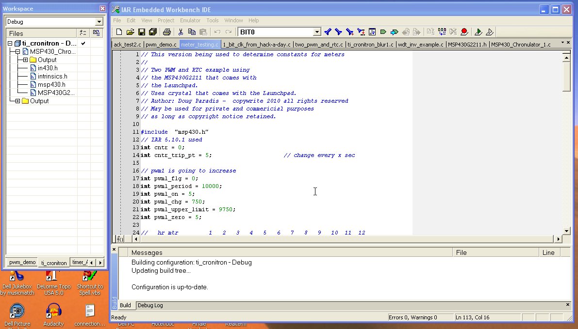
In this step I would like to give the basic procedure for using the IAR compiler/debugger. Later in the project we will be tuning the adjustment arrays for the meters to compensate for nonlinearities. We will end up going through this process several times. Also, I wanted to point out steps 3 and 4, which caused me to do some head scratching because I didn't know about them.
1. Open existing or create new workspace.
2. Create new project for Chronulator.
3. Select Project -> Options... -> category: general options and change
device to MSP430G2211.
4. Change Category to "Debugger" and change "Driver" to FET Debugger.
5. Hit ok.
6. Create new file (file -> new -> file)
7. Copy/paste code into new file and name file.
8. Go to the workspace window, your Chronulator project should be there. If not
select the correct tab at the bottom of the window.
9. Right click the project in the tree and select add -> file "your file name .c".
Your file should be added to the project tree.
10. Right click the project again and select Rebuild all.
You can now expand the "your file name.c" branch of the tree and see the
h files that are added.
11. Now to put the code on your chip, select the "make" icon or menu:
Project -> make, or F7 (to make).
12. Make sure that your Launchpad is plugged in to a USB port and that the
Launchpad board has the MSP430G2211 chip on board (or has been connected via
"spy-by-wire" with the project board) and the 32K crystal has been installed.
13. Select the "Download and Debug" icon or menu: Project -> Download and Debug,
or Ctrl+D. This will download the code to the chip and start the debugger.
14. If everything is ok, your computer will pause for a brief time and then a new set
of toolbars will show up. This is the debugger. For the simplest case, we can
hit the "Go" toolbar icon, watch the circuit operation and then hit the
"Stop Debugger" toolbar icon. When you stop the debugger, the toolbar
will return to their normal state.
If you make changes to the code you cycle through steps 12 to 14.
The Code
Downloads
Helpful Gizmos
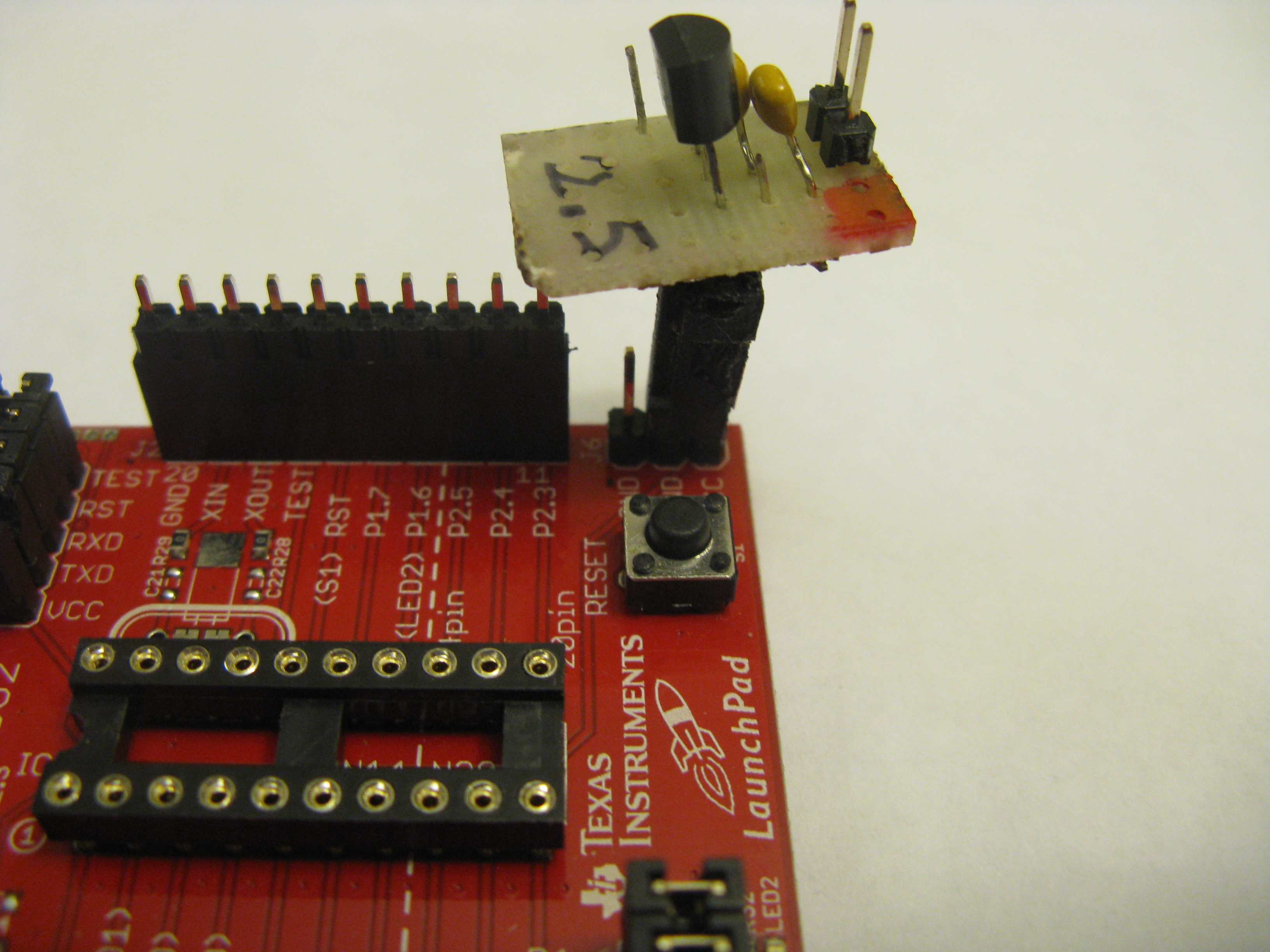
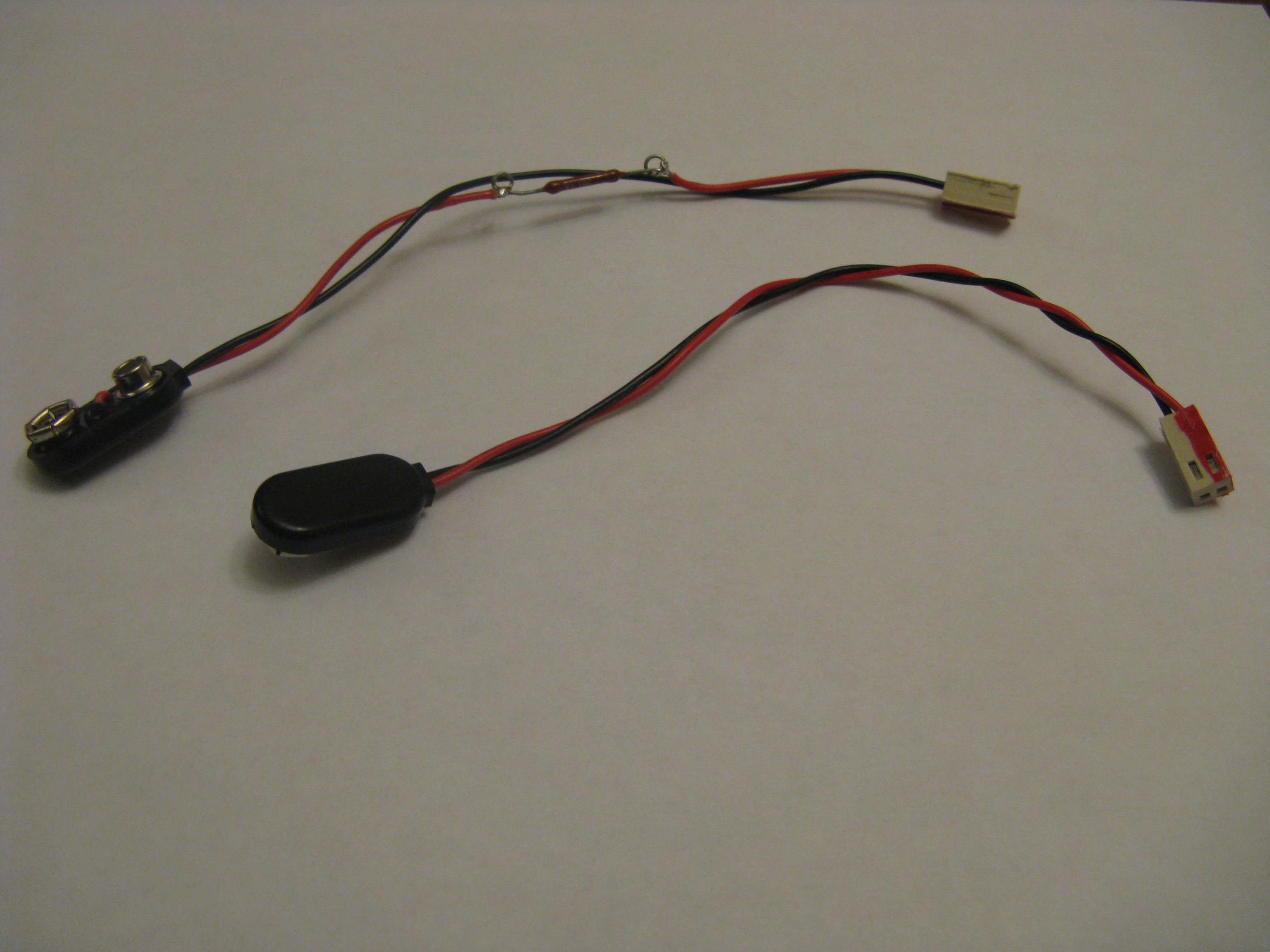
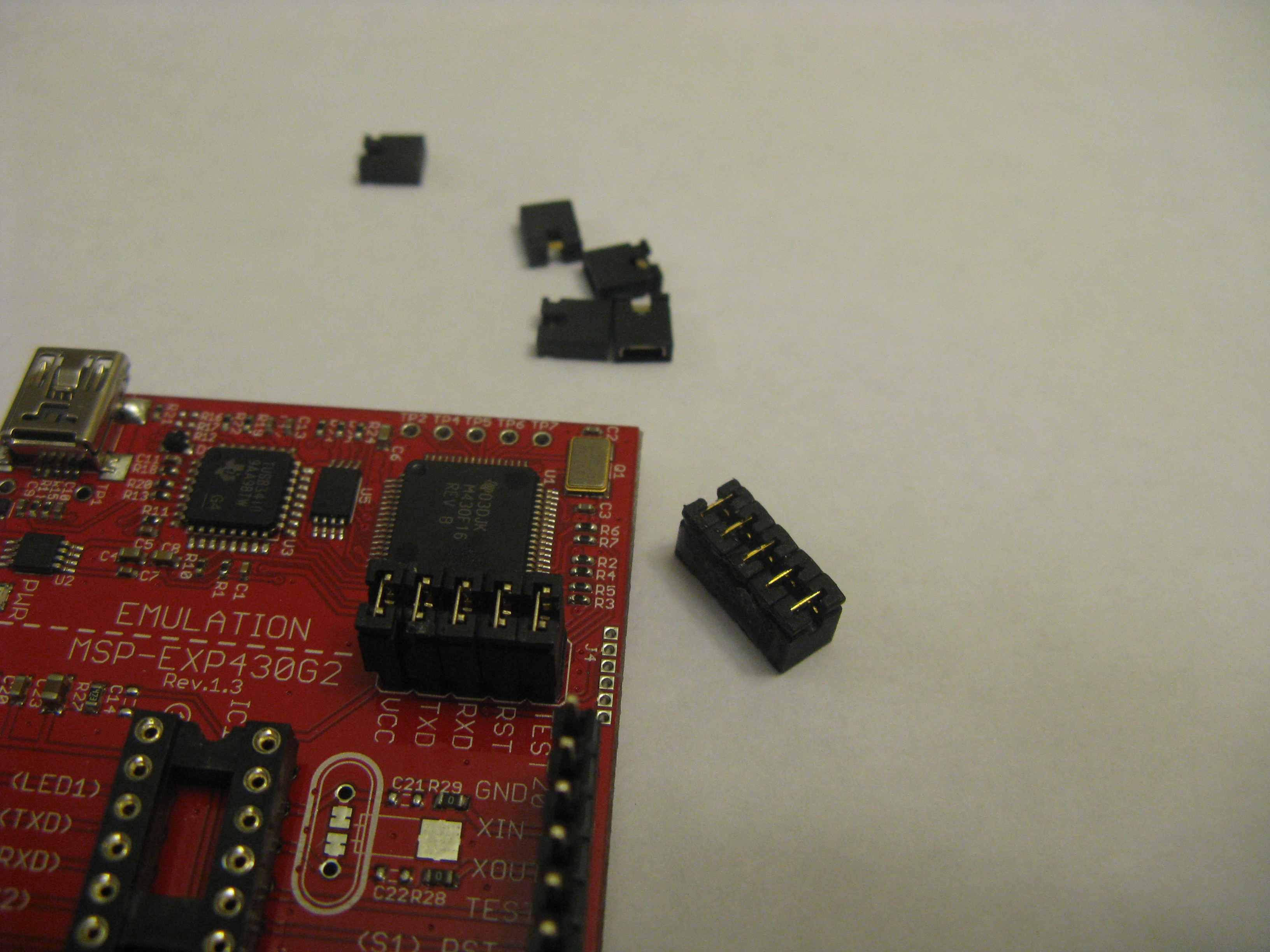
While I was building the Chronulator, I ended up constructing a few useful gizmos. They are not necessary, but I have found them helpful. They also can be used over again on other Launchpad projects that use batteries and require a regulated voltage. The gizmos consist of a small 2.5V regulator that can be piggybacked to the Launchpad, a power line for the battery pack to the regulator, and a super glued block of 5 jumpers to speed putting in and removing the jumpers on the Launchpad. The schematic for the little piggybacked regulator is the same as the power supply shown in step 2.
Changing the Scales of the Panel Meters
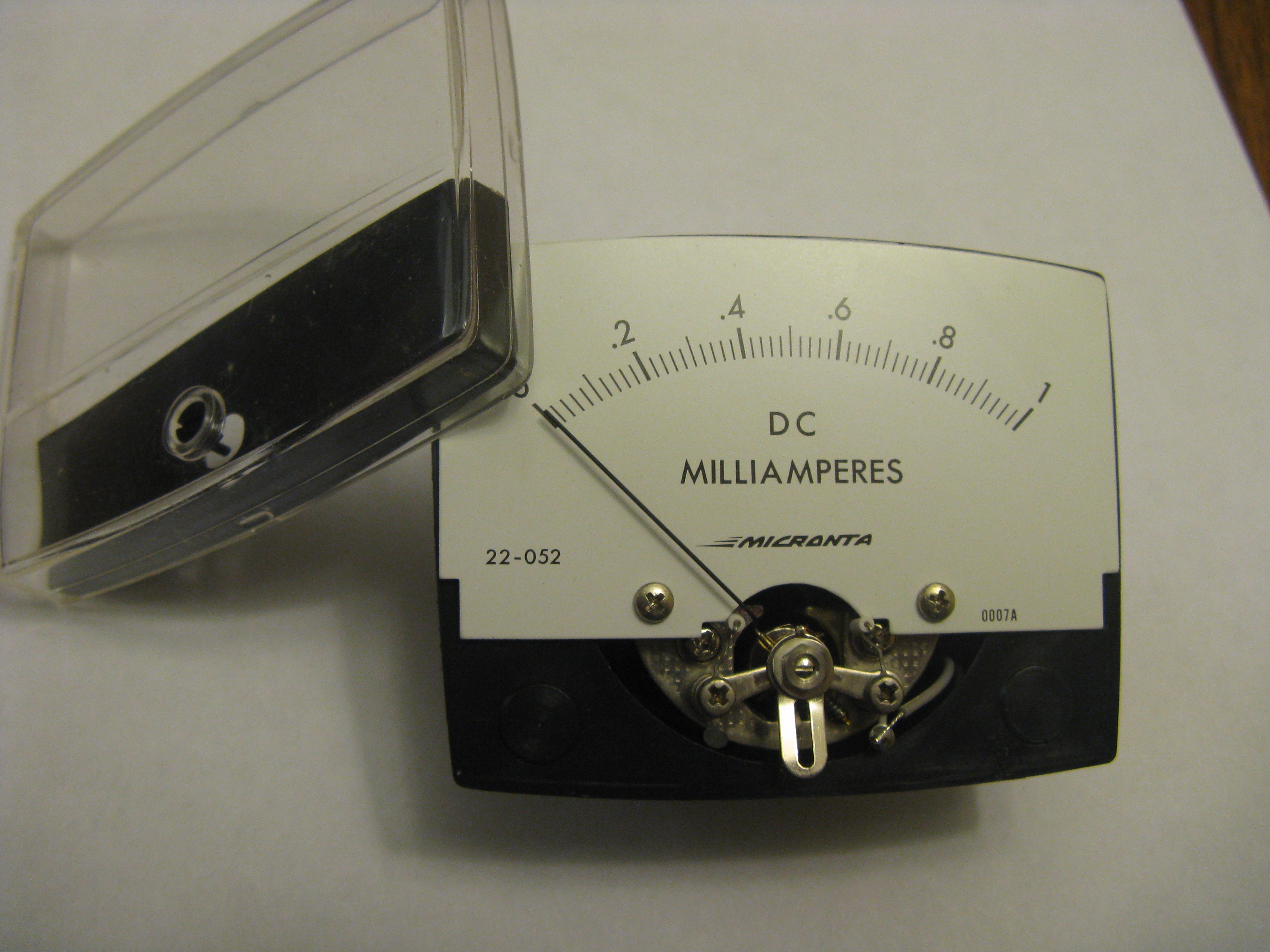
You can always buy new panel meters, the going price is about $9 for a 2 - 2.5 inch meter made in Asia. The nice thing about these meters is you can select sensitivities from 50 uA through 1mA for the same price. One source is BG Micro (http://www.bgmicro.com). The downside is they are a little boring.
When you select a meter, make sure that you can easily remove the front. If the front is glued to the back of the meter, pass on it and move on. When you remove the front of the meter, you typically find that the face is attached with a couple of screws to the meter movement.
I used 2 different methods to change the scales on the panel meters of my chronulator. On the minute meter, I printed out a new scale on plain paper and used a glue stick to stick it over the old scale. On my hour meter, I printed out a new face the same size as the old face on photo paper and flipped the face plate and used a glue stick to attach the new face to the backside of the plate. In this case, I wanted to retain the look of the original face plate by keeping the manufacturer's name and "Direct Current" heading. The best way to do this is to scan the original face plate using a flat bed scanner. The scanned image then becomes the background layer of your new meter face in the graphic program you use.
The ShareBrained Technology site has several meter faces that you can download. They fit the meters used in their Chronulator kits. You might get lucky and be able to use one of them.
There is also a meter scale program that can be used that has a free limited version available from Tonne Software, http://www.tonnesoftware.com . I haven't used it.
One last note, the hour meter scale goes 12, 1, 2, 3, 4, 5, 6, 7, 8, 9, 10, 11, 12. It does not go 1, 2, 3, 4, 5, 6, 7, 8, 9, 10, 11, 12. This is because the Chronulator works like an analog clock and sweeps the hour hand as the hour progresses.
Prep for Using "spy-by-wire"
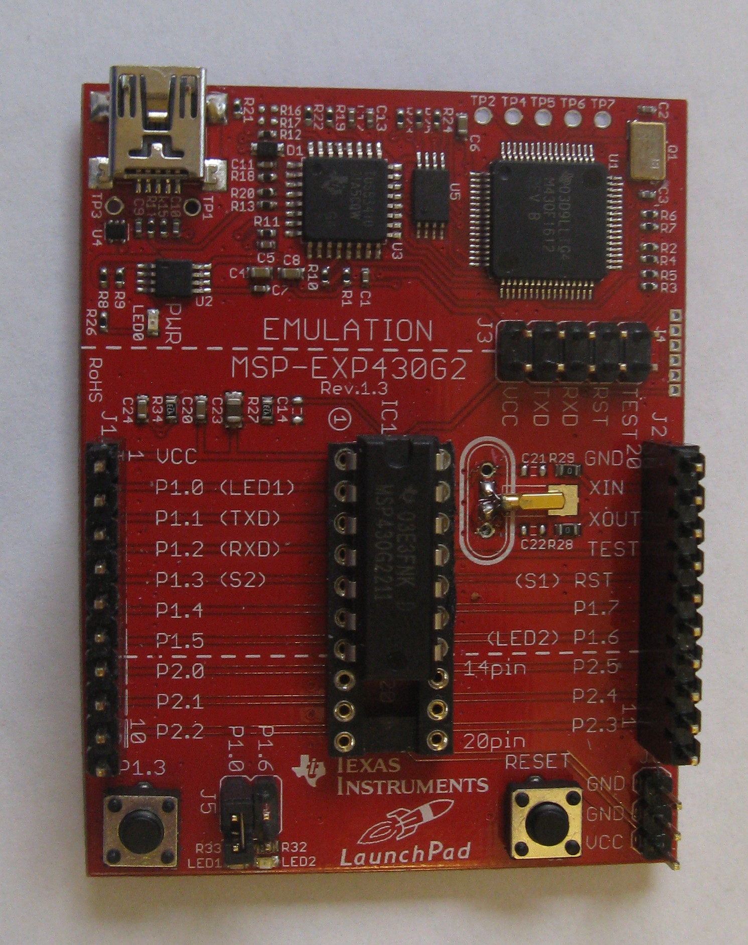
There are several ways that you can proceed. One way is to fabricate the circuit on the breadboard and move the chip to the Launchpad each repetition of adjusting the array. The other way is to keep the chip in the Launchpad and isolate the prototyping portion of the board. This is done by removing the 5 jumpers from terminal block J3 and supplying 2.5V to the external power terminal block J6. When you want to program the chip you have to restore the jumpers and remove the external power supply. If you use this second method you have to hookup the meters and the buttons.
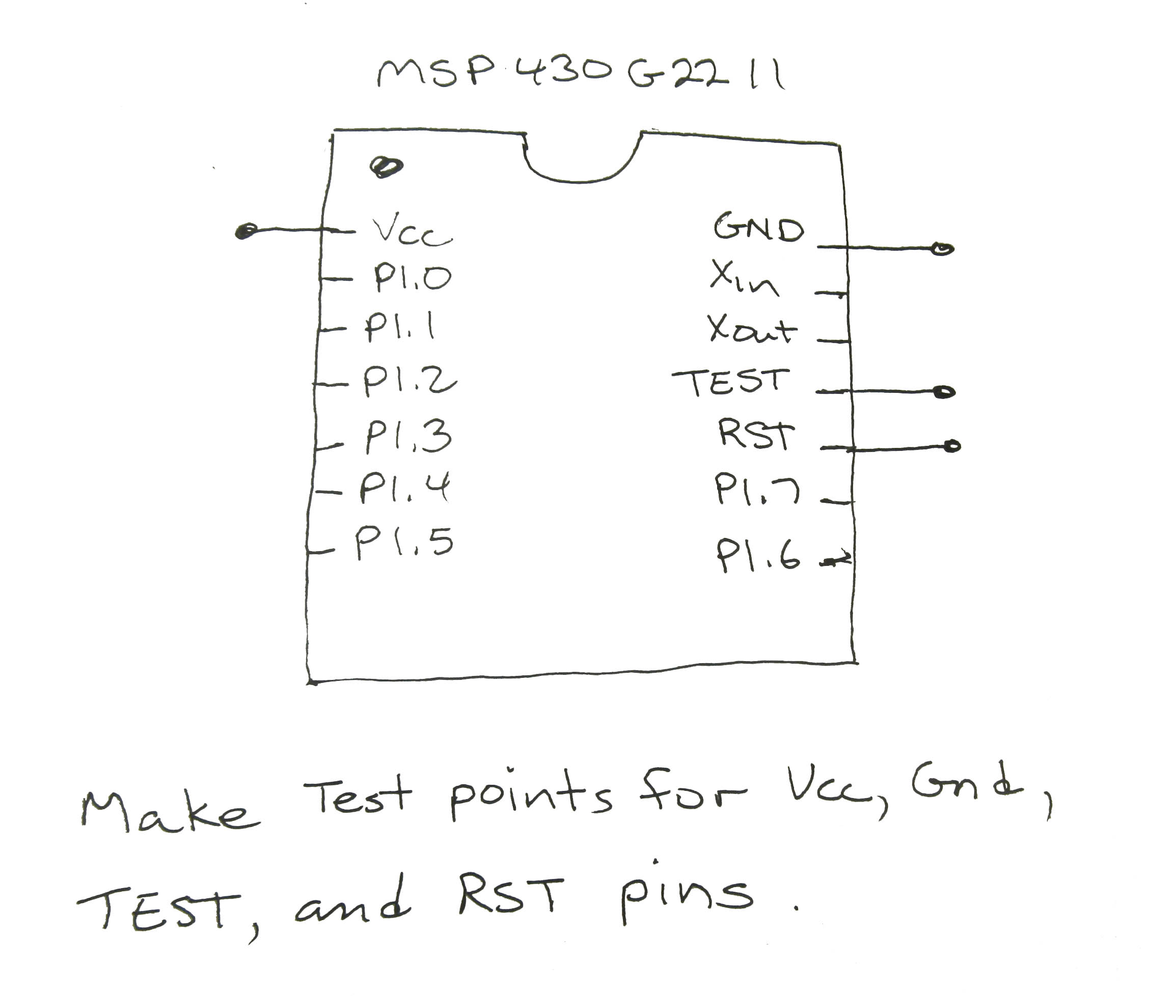
There is a third way, using the "spy-by-wire" interface. In this method when we build our project breadboard, we include some test points. The test points allow us to connect between the project breadboard and the Launchpad. We can program our microcontroller without ever removing it from the project board. The Launchpad is used simply as a programmer. This is the method that I recommend you use.
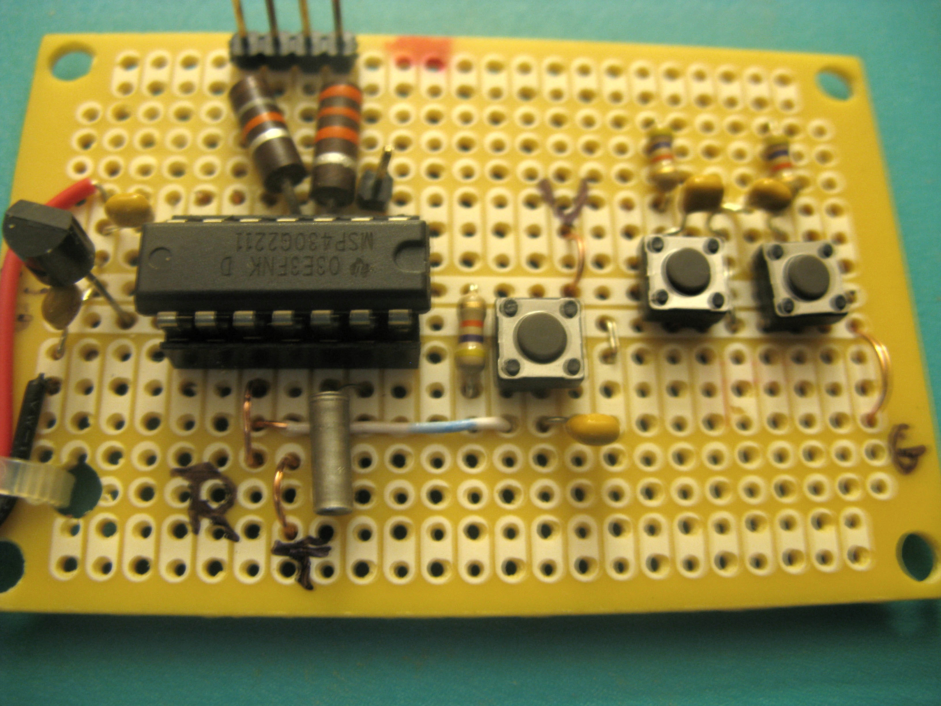
Adding the Test Points:
There are 4 test points that need to be added.
1. Vcc (IC pin 1)
2. Gnd (IC pin 14)
3. Test (IC pin 11)
4. RST (IC pin 10)
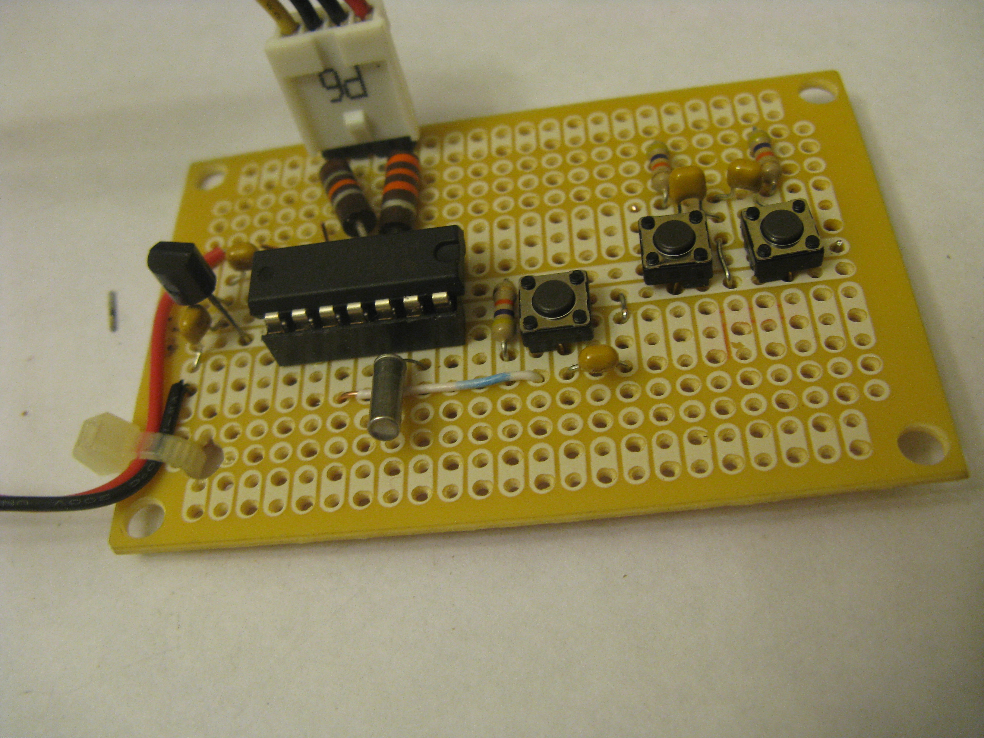
The simplest way to add a test point is to make a little U of wire and attach it at the desired location. See the pictures below.
Using "spy-by-wire"
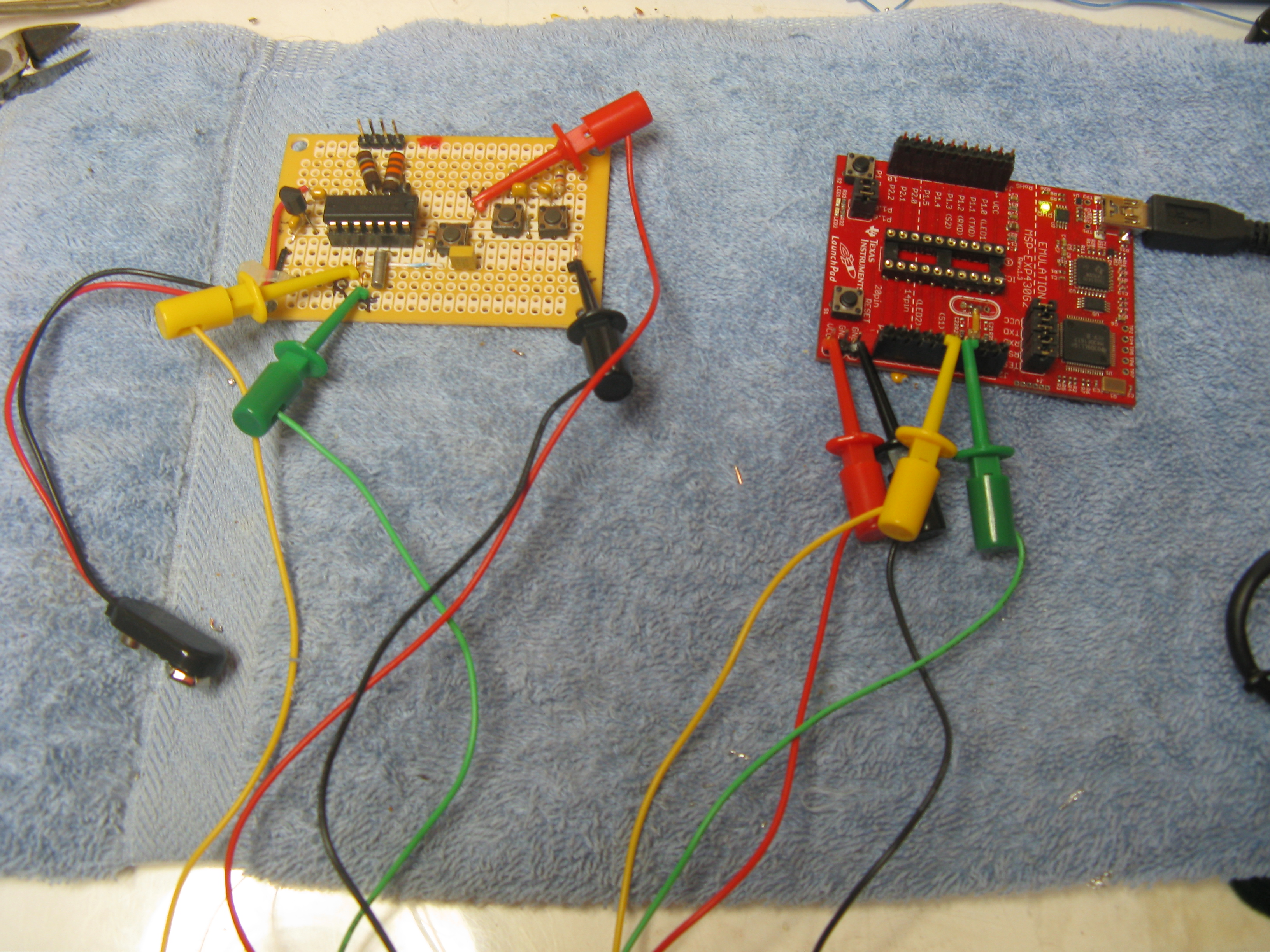
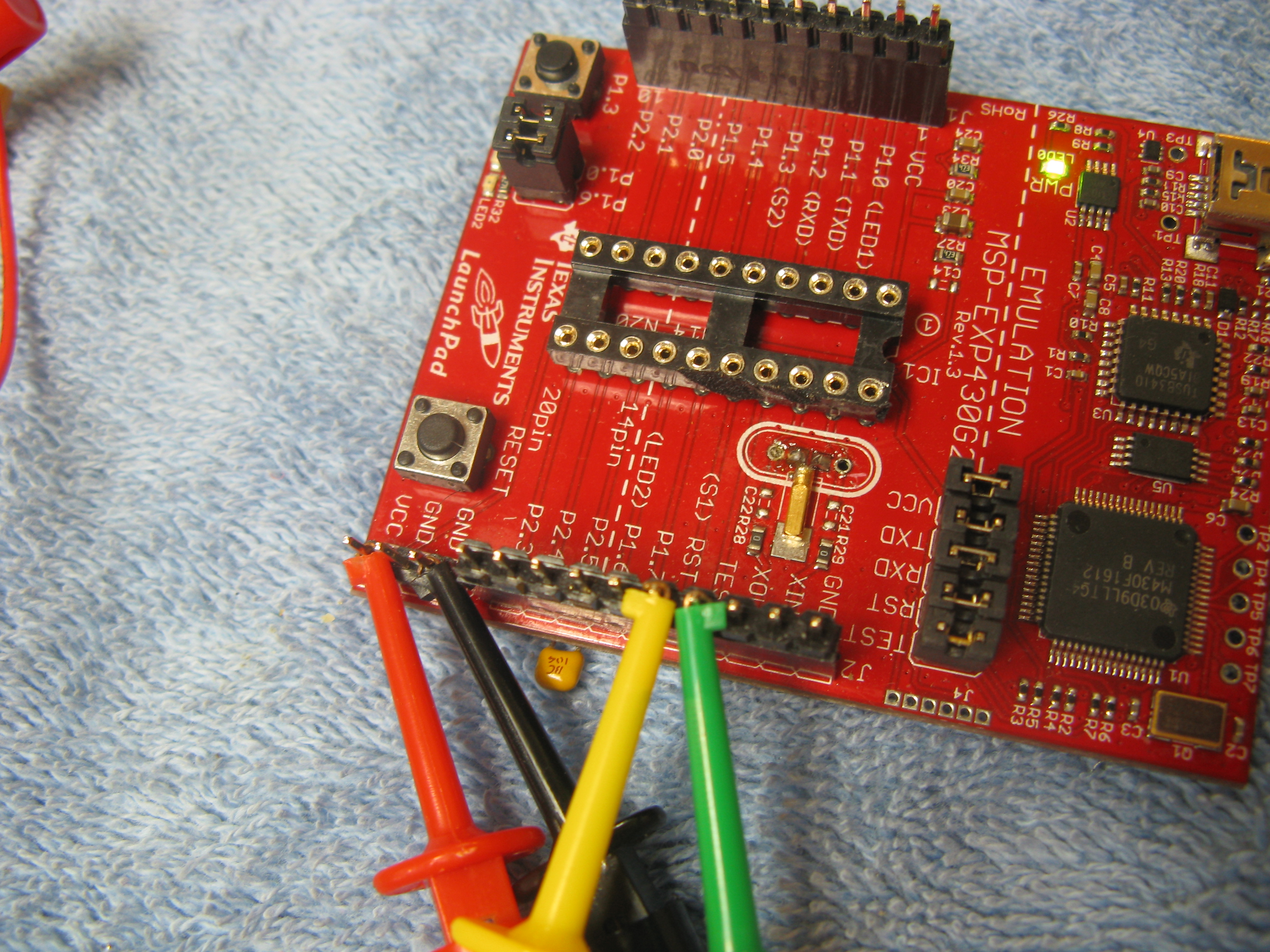
Below is a picture of the connections required to use the "spy-by-wire" interface.
Programming Connections:
1. Disconnect the battery pack from the project board.
2. Connect jumper from Launchpad J6 terminal "Vcc" to project board Vcc test point.
3. Connect jumper from Launchpad J6 terminal "Gnd" to project board Gnd test point.
4. Connect jumper from Launchpad J2 terminal "TEST" to project board TEST test point.
5. Connect jumper from Launchpad J2 terminal "RST" to project board RST test point.
note: All 5 jumpers of Launchpad terminal J3 should be in place.
When the two boards are connected in this manner, you can program the microcontroller while it is in the project board. You use IAR Embedded Workbench KickStart just as you would if the whole project was on the Launchpad.
Since we are using a different voltage supply voltage (2.5V instead of 3.3V) in this project, you must break the connections when you are testing the project board. Note: If you are using 4 AA batteries and a 3.3V regulator I would still break the connections to be sure that voltage you use to calibrate the meters with is correct.
Testing Project Board Connections:
1. Disconnect all four of the project board connections to the Launchpad.
2. Connect the battery pack to the project board.
3. Press the Reset button.
Basic Checks Before Putting MSP430 Into Project Board

Here are some basic checks that you should make to your wired up project board before inserting the MSP430 chip. They can all be done from the top side of the breadboard.
Using an multi-meter as an ohms meter:
1. Visually double check that you have placed the right pins of your regulator into
Vin, Vout, and Gnd.
2. Check between the pins in the IC socket for pin to pin shorts. There should
not be any shorts. You will see ~94k ohms between pins 6 and 7 (2 x 47k).
3. Check between pin 1 of the IC socket and Vcc. You should see a short.
4. Check between pin 14 of the IC socket and Gnd. You should see a short.
5. Check between pin 1 and pin 14 of the IC socket. You should see an open.
6. Check across Vcc and Gnd and push each button in turn. As each button
is pushed the meter should read from infinity to 47k.
7. Place the multi-meter positive lead in pin 6 of the IC socket and the negative
multi-meter lead on the junction of the 47k resistor and the minute advance
button. You should see a short. Do the same for pin 7 and the junction of
the 47k resistor and hour advance button. Also do the same for pin 10 and
the junction for the 47k resistor and the Reset button.
8. Place the positive multi-meter lead on the positive minute meter pin of the
meter junction block and the negative multi-meter lead on IC socket pin
3. You should see the resistive value of your minute meter's current
limiting resistor.
9. Place the positive multi-meter lead on the positive hour meter pin of the
meter junction block and the negative multi-meter lead on IC socket pin
4. You should see the resistive value of your hour meter's current
limiting resistor.
10. Place the positive multi-meter lead on the negatives (2) of the meter
junction block and the negative lead on Gnd. You should see a
short for each negative.
10. Make sure that the 32k Hz crystal is installed at IC socket pins 12 and 13.
11. Visually triple check that you have placed the right pins of your regulator into
Vin, Vout, and Gnd.
12. Plug in the battery pack, place the multimeter on a voltage scale and
measure the voltage between Vcc and Gnd. You should see 2.5V.
13. Unplug the battery pack.
14. Install the MSP430 chip. Make sure that pin 1 of the chip (upper left pin
with the u shaped indent to the top, and top of chip facing you) is installed
in pin 1 of the IC socket.
Tuning the Meter Calibration Arrays
The 2 arrays are named m_cal (used with minute meter) and h_cal (used with hour meter). The 12 members of the array represent the number of clock pulses required to move the meter movement one major division. In the case of the hour meter, this is one hour. In the case of the minute meter, this is 5 minutes. The period for the PWM for both meters is the same. It is 10000 clock pulses. The sum of all 12 members of a given tuning array will be less than the period. I tried to leave about 10% of the PWM period as head room. So typically the arrays will sum to about 9000.
The minute scale has 5 sub-divisions (1 min) per major division (5 mins). The hour meter sweeps every major minute division (5 mins), so there are 12 sub-divisions for the hour meter per each major division (1 hr). For this reason the numbers in m_cal should be divisible by 5, and the numbers in h_cal should be divisible by 12. This isn't an absolute requirement, but using other numbers will result in remainders being dropped and could cause confusion.
Let us look at an example. If the hour array (h_cal) is equal to h_cal[] = {720, 708, 696, 736, ...}, to move the meter to 3 O'clock you need to set the PWM pulse count to the sum of 720, 708, and 696, which is equal to 2124. If you were at one O'clock and wanted to go half way between one and two you would add 360 (708 divided by 2 and rounded up to the next number divisible by 12) to 720.
The arrays that are in the program should be close to what you need regardless of the meter sensitivity you use, since you change the resistors to change the current provided to the meters. You should only have to tune them up.
How to tune the meter cal array:
Step 1:
We will start with the minute meter. To make things easier we will change the minute advance from 1 minute per button push to 5 minutes per button push. Locate in the code the following lines and un-comment them. They are part of the port_1 interrupt service routine.
// for (int j = 1; j <= 4; j++) // inc 4 mins Uncomment these 4 lines when tuning m_cal
// {
// one_min();
// }
Disconnect the battery pack of the project board and make the "spy-by-wire" connections between the project board and the Launchpad. Load the modified program onto the MSP430. Now everytime we push the minute increment button the minute meter will jump 5 minutes instead of 1.
Step 2:
Remove the "spy-by-wire" connections form the project board test points and reconnect the battery pack. Press the Reset button. Next adjust the zero of the meter. Then press the minute increment button and observe where the meter comes to on the scale. It should be close to 5 minutes. Write down whether it is less than 5, exactly at 5, or greater than five. Press the minute increment button again and determine how close to 10 minutes it is. Do this to about 20 minutes (4 button presses).
Step 3:
Disconnect the battery pack of the project board and make the "spy-by-wire" connections between the project board and the Launchpad. Using your notes adjust the first four members of m_cal based on what you observed. If the meter was higher than expected then adjust the member down. If the meter was below what you expected adjust the member up. Start from the lower end of the scale and move up. If you see a trend where each time you push the button the difference becomes greater from the desired point reduce all the numbers. If the first one is off a little and the others seem to be off about the same offset, than adjust the first member that is off. I usually make adjustments of 5 or 10, unless I am way off then I make adjustments of 20. After you have made the adjustments to m_cal, enter the debugger and download the changes to the chip.
Step 4:
Remove the "spy-by-wire" connections form the project board test points and reconnect the battery pack. Observe the results of the changes you made. Repeat steps 2 (without adjusting the meter zero), 3, and 4 as needed, slowly moving up the scale (25 minutes to 60 minutes) until every time you hit the minute increment button, the meter goes exactly to a 5 minute major division of the scale.
Step 5:
When you are happy with the tuning of the minute meter you can move to the hour meter. I suggest that you re-comment the 4 lines we uncommented in step 1 and make sure the changed code gets back on the chip.
Step 6:
The tuning of the hour meter h_cal array is similar to what you did on minute meter. When you hit the hour increment button it should jump to the next hour on the scale. The adjustments should be multiples of 12 instead of multiples of 5. I typically make adjustments of 12 and 24.
I know this procedure sounds difficult, but it is really simple once you determine how much the meter will move to your adjustment. The whole thing should take no more than 30 minutes.
Determining the 32.768 KHz Crystal's Load Capacitance
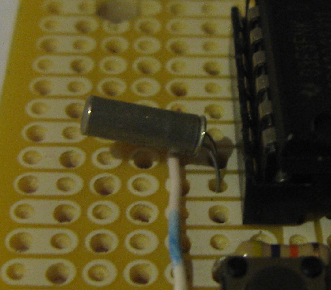
Differences in circuit layout on the project board (or PCB) complicates the problem by adding more capacitance. On the plus side, the MSP430G2211 has the ability to provide different capacitance values to the circuit. We can change the capacitance value within a range by software. In the code you will find the following lines. We will select one based on the result of our tests.
// crystal Cload capacitor adjustment - only one line of next four should be uncommented
// BCSCTL3 = LFXT1S_0 + XCAP_3; // 32768KHz crystal, 12.5 pF
// BCSCTL3 = LFXT1S_0 + XCAP_2; // 32768KHz crystal, 10 pF
BCSCTL3 = LFXT1S_0 + XCAP_1; // 32768KHz crystal, 6 pF
// BCSCTL3 = LFXT1S_0 + XCAP_0; // 32768KHz crystal, 1 pF
Impact of an incorrect selection of C_load:
When C_load for a crystal is too high the crystal oscillates at a slightly lower frequency. Likewise, when the capacitance is too low the crystal will oscillate slightly faster. For a 32.768 kHz crystal, we are generally talking about 1 or 2 Hertz. One or two Hertz, you say, that doesn't sound like much. What is the big deal?
The MSP430's 16 bit timer resets every 2^15 or 32,768 pulses. If we use a crystal that provides exactly 32,768 pulses per second, then the timer will reset every second. If the crystal is actually running at 32,766 pulses per second, the effective MSP430 "second" is
1 sec + 2/32766 sec = 1 1/16383 sec
After 16383 seconds (~4.55 hours), the Chronulator would be one second behind a clock with a crystal running at 32,768 Hz. In other words, it would lose a minute every 11.375 days.
Crystal Pulses Time to be Time to be Fast /
Frequency Off off 1 sec. off 1 min. Slow
----------------------------------------------------------------------------------------
32,766 -2 4.55 hrs. 11.375 days Slow
32,767 -1 9.50 hrs. 22.750 days Slow
32,768 0 -- should keep good time --
32,769 1 9.50 hrs. 22.750 days Fast
32,770 2 4.55 hrs. 11.375 days Fast
How to select the proper value of C_load:
Step 1:
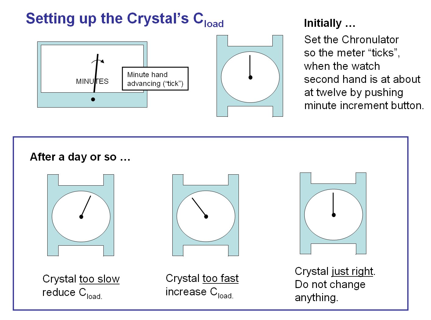
Select a watch that keeps very good time, or use your computer or cell phone clock, to be your standard. Place your standard next to the Chronulator. Wait until your clock' second hand is at about at 20 seconds and quickly set your chronulator time to just one minute behind your clock. When the clock's second hand approaches 12 (or 60 if digital) push the chronulator's minute increment button to bring the two clocks into sync. Since you will most likely be off a second or two, observe both clocks another minute to get the exact second that the Chronulator's minute meter advances ("ticks"). Write down the date, time, and the second of the "tick". You will not remember.
Step 2:
Wait a day or two, then check to see if the both clocks are still in sync. If you are not sure wait a few more days, by that time if they are off, you should be able to tell. If you still can't tell, then things are ok and no adjustment will need to be made.
Step 3:
If the clocks have lost sync, adjust C_load capacitance by changing one of the commented lines above in the c program and commenting the setting that was in use. If your standard clock is ahead of the Chronulator, the Chronulator is slow. Decrease the capacitance value. If your standard clock is behind the Chronulator, the Chronulater is fast. Increase the capacitance value.
What if your clock is still fast and you can't increase the capacitance any higher? In this case, you could add 2 very small capacitors (6-12 pF) from each of the crystal's leads to ground. I would just try another crystal. If you decide to add capacitors you can get them from Mouser (6 pf - Mouser part # 81-RPE5C1h6R0D2P1B03 $0.18, 12 pF - Mouser part # 81-RPE5C2!120J2P1Z03 $0.23).
What if your clock is still slow and you can't decrease the capacitance any lower? In this case, check if you can reduce the capacitance on your project board. This can be done by making sure that the crystal is close to IC pins 12 and 13. Also make sure that the runs for the crystal are short. If this doesn't help, I would try another crystal from another source.
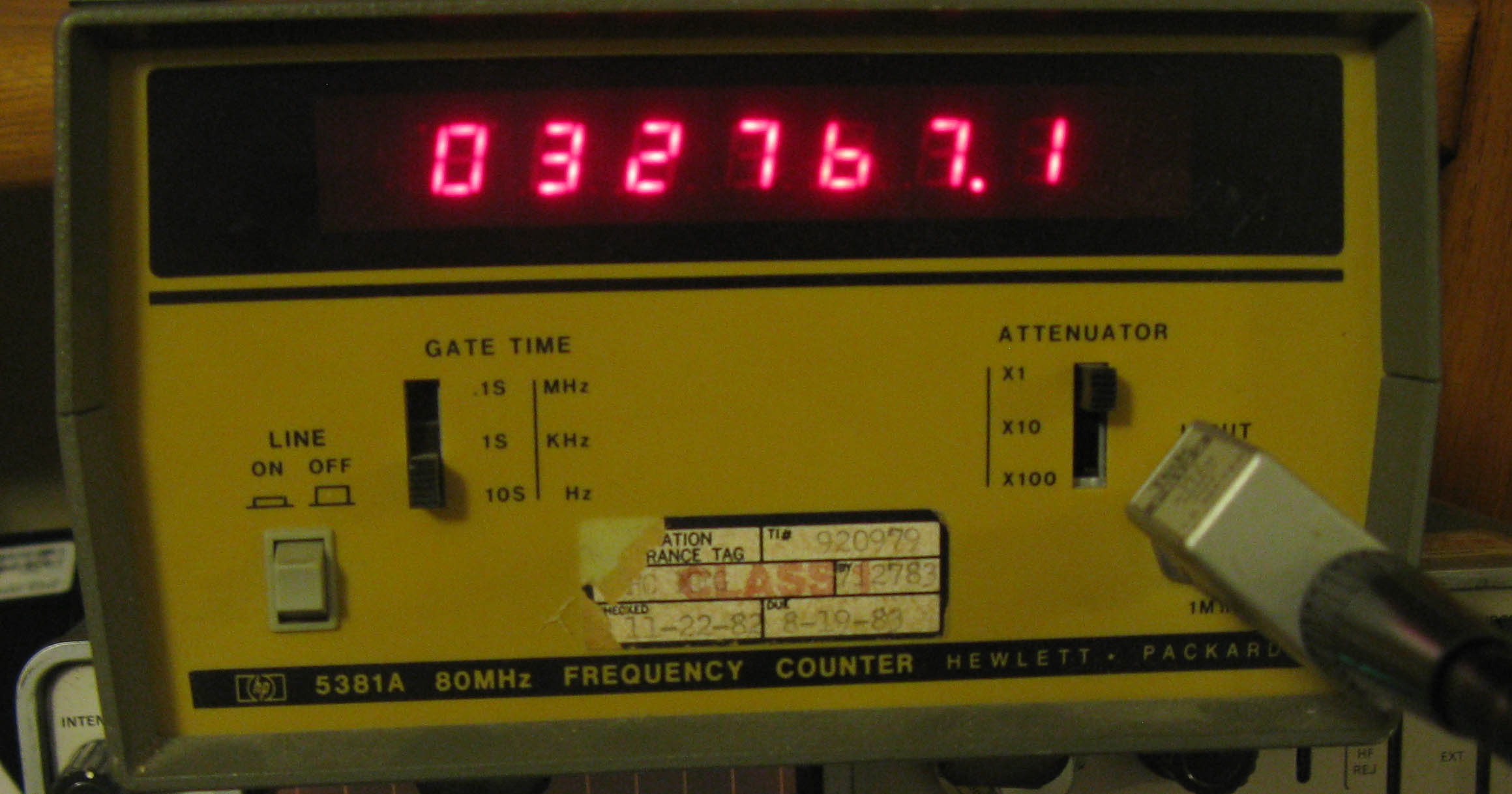
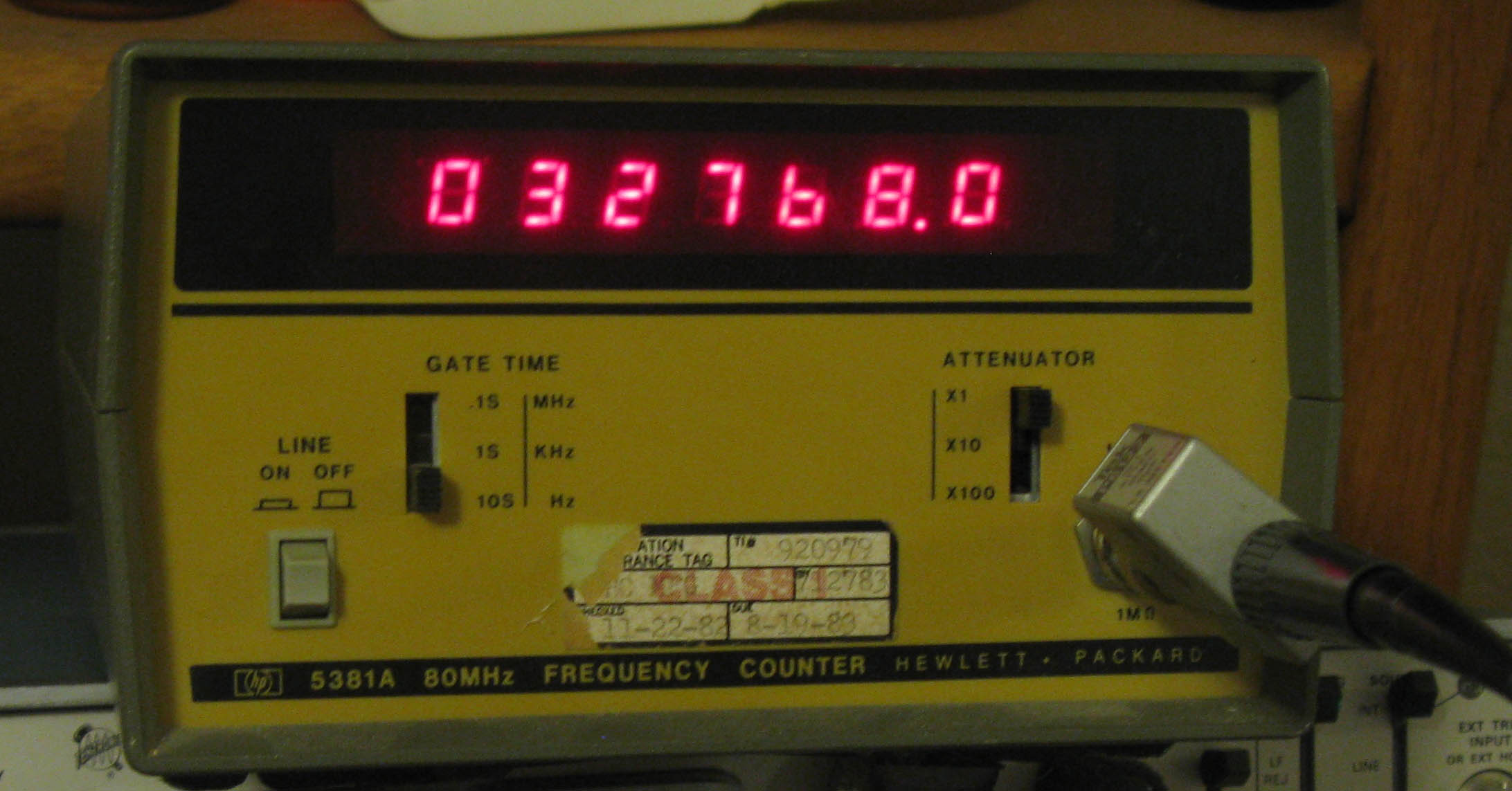
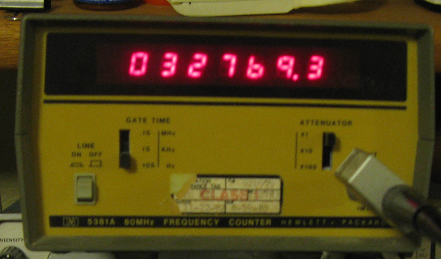
By the way, if you have a pulse counter, you can make ACLK available at P1.0 with a simple program (attached below) and check the crystal's frequency in the project board directly. I used this technique to observe changes on my Launchpad / crystal setup. I found that the recommended setting of 12 pF (XCAP_3) was a little too high C_load. Look at the different photos below to see the results of different XCAP settings. You might wonder about my counter calibration. I feel very comfortable that it is correct, because I was able to achieve a 32,766 Hz setup on my project board / crystal combination. With this setup, I observed the 1 second loss every 4.55 hours shown in the table above. When I optimized it for C_load (i.e., observed freq = 32,768 Hz), the clock was right on the money.
Downloads
FAQ
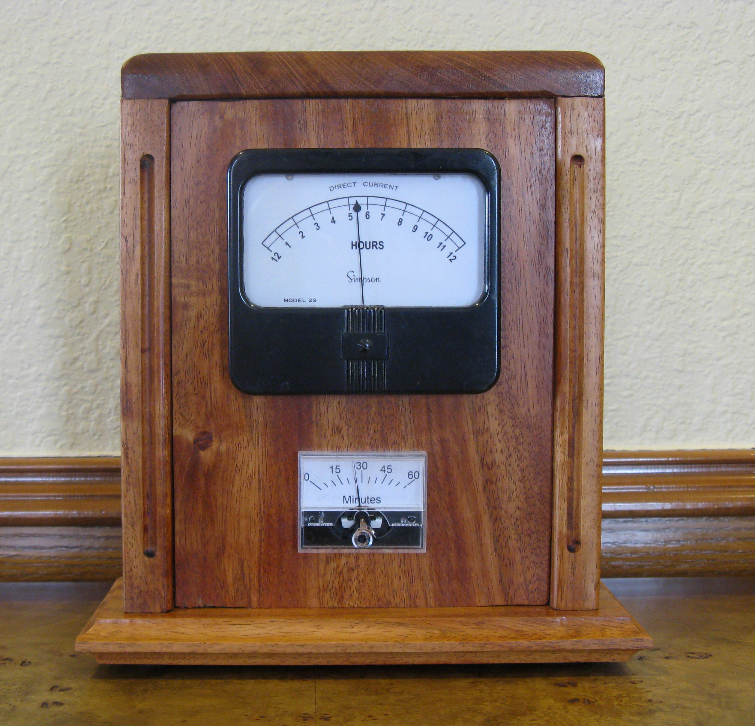
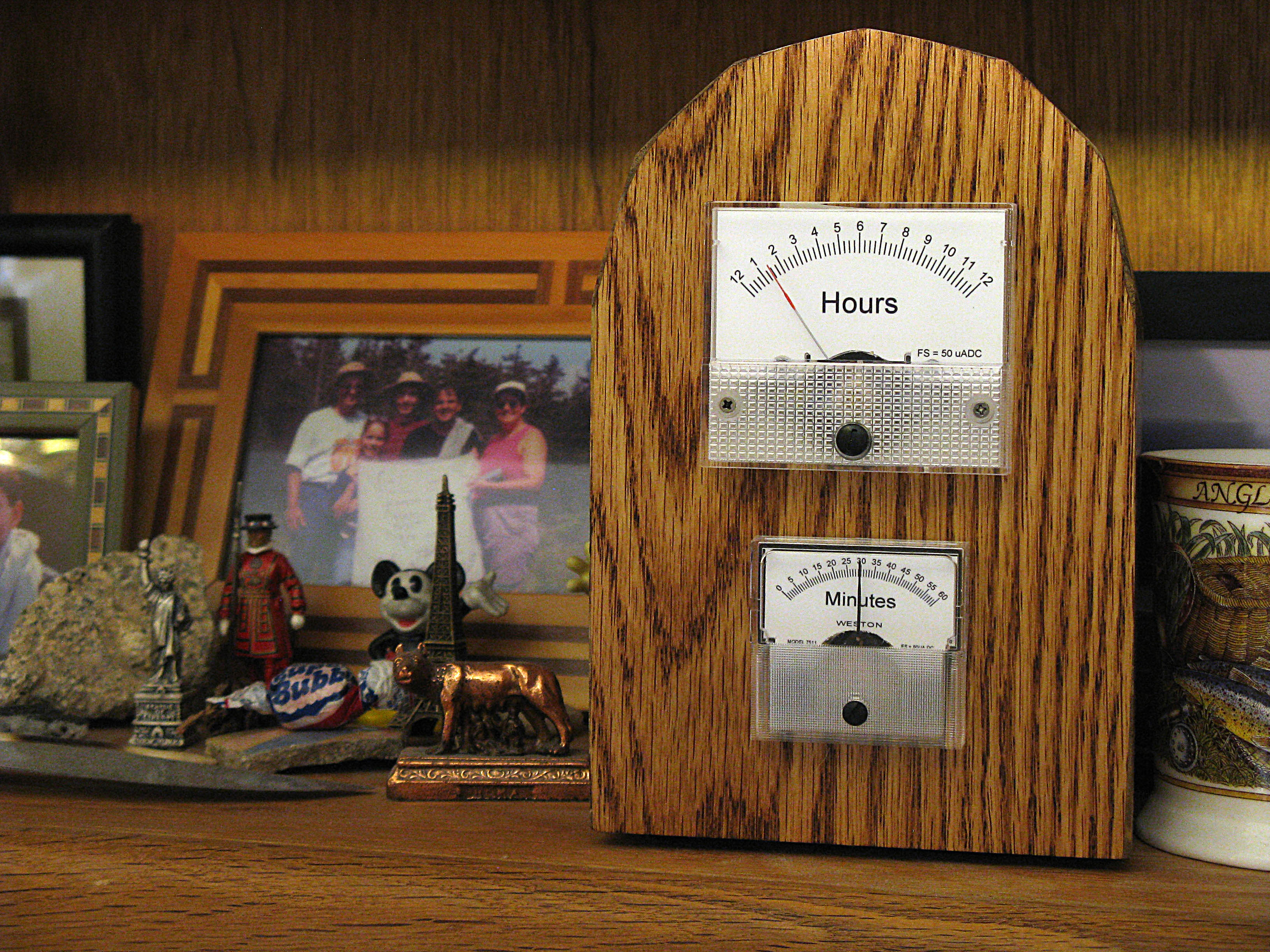
Q: What about a case?
A: See my mantel clock case for this project at:
https://www.instructables.com/id/Mantel-Clock-Case-for-Chronulator-Meter-Clock
Q: How does the code work?
A: The watchdog is set to delay mode and creates interrupts at 1 second intervals, using ACLK and the 32.768 kHz watch crystal. This allows you to count seconds. Timer_A interrupts are used to generate 2 independent PWM outputs which drive the meters. Port_1 is used to provide interrupts for the minute and hour increment buttons. You will note that there is no loop in the main subroutine. The program is completely interrupt driven after it reaches the end of main(). When not servicing an interrupt the MSP430 is in LPM0.
Q: Why doesn't "spy-by-wire" work?
A: The most likely cause is that you have a 0.1uF capacitor parallel to the Reset button instead of a 1nF (0.001uF) capacitor.
Q: Can I use a 3.3V voltage regulator instead of a 2.5V one?
A: Yes, a 3.3V voltage regulator can be used, but you should use 4 AA batteries (6V) instead of 3 (4.5V). The battery count is increased so the batteries can age with out causing PWM calibration problems. The regulator should be LDO and low Iq.