MSD Two-step Installation
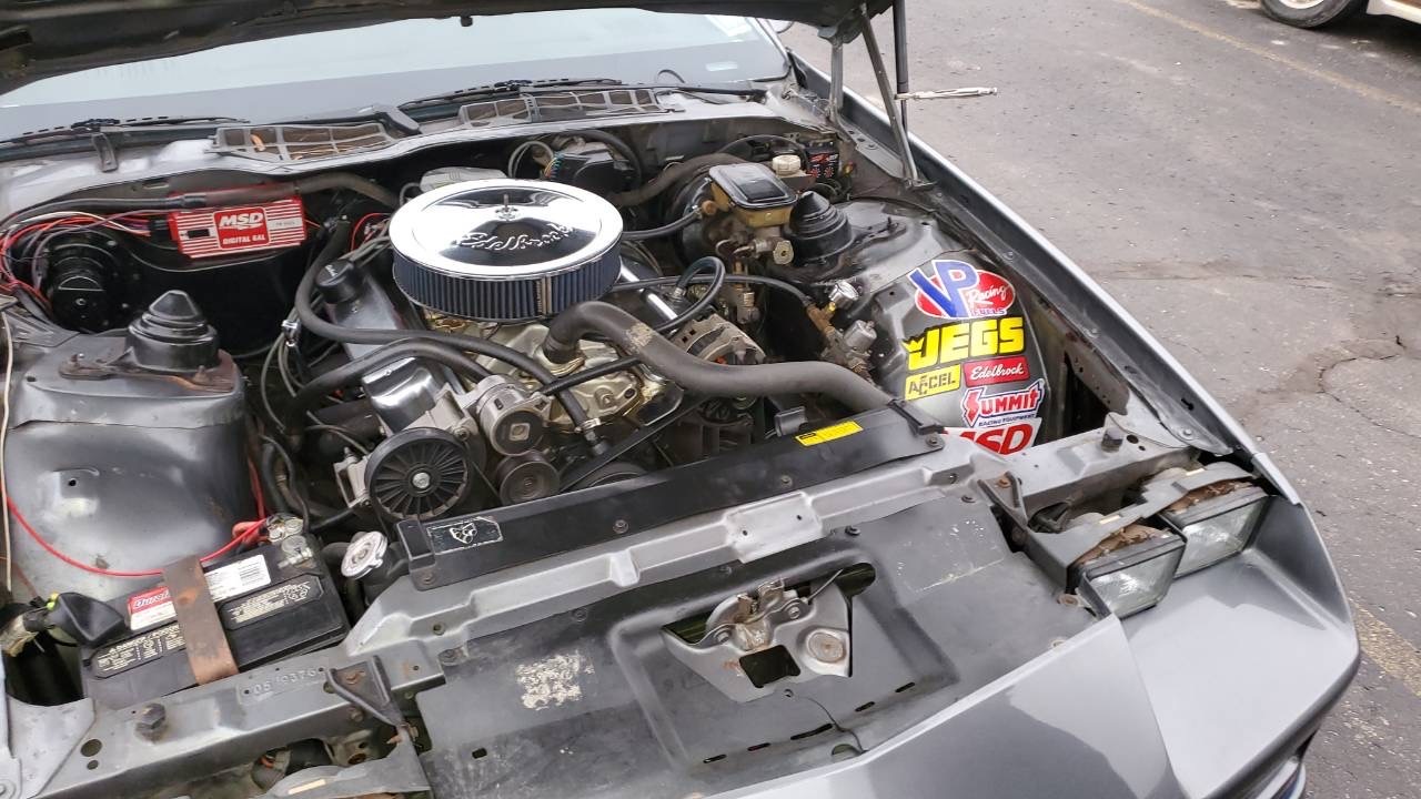
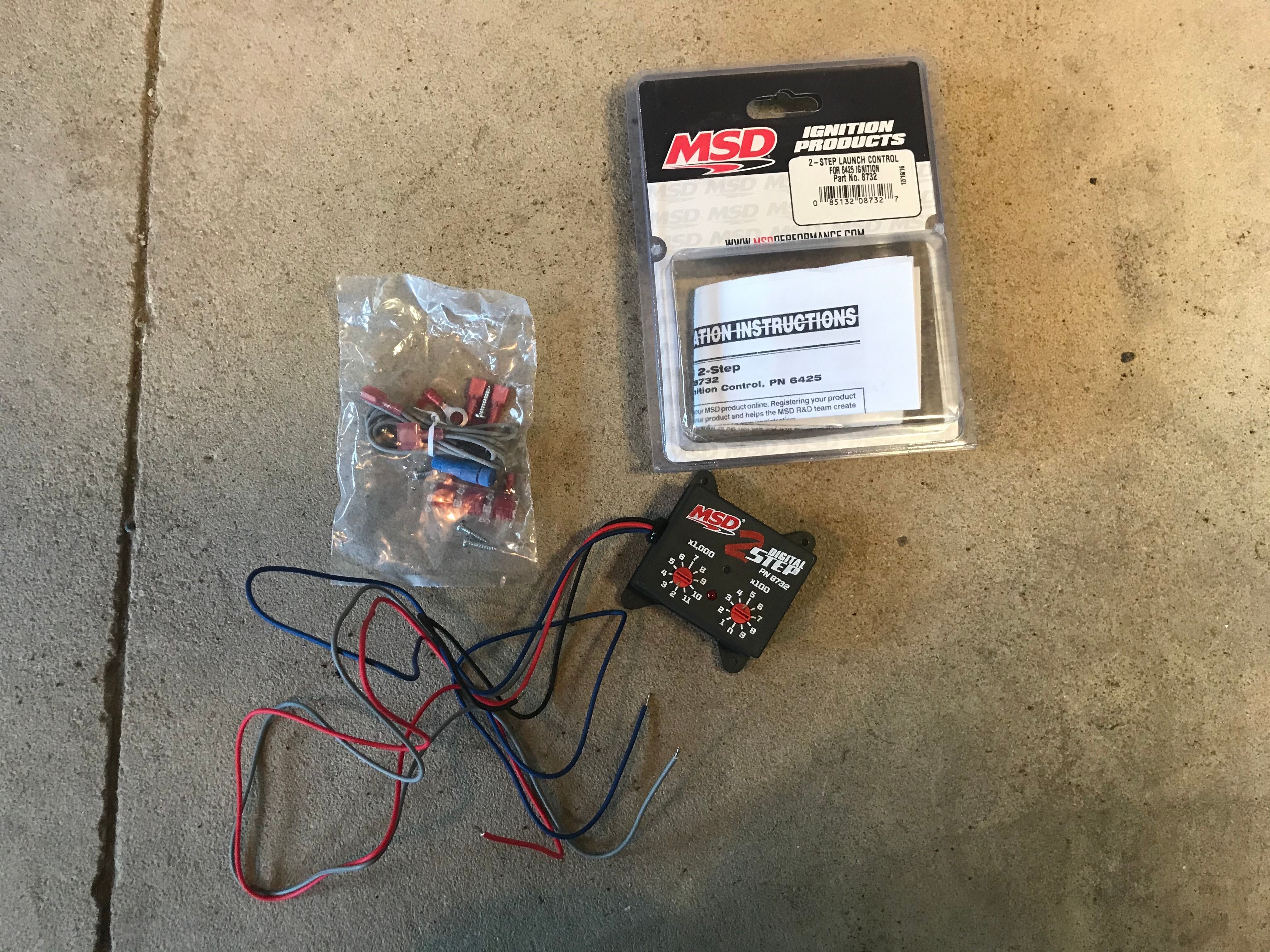
This instructables was a projected assigned to me from my comm professor. The idea came to me when my friend Trent was telling me that he wanted to install a two-step into his car. I then asked him if i would be able to install it for him as my project and he agreed. Being a student who is studying electrical engineering, I thought this project would not only help me broaden my knowledge but be an interesting project as well.
Worried about bad launches at the drag strip? Well, this instructable will take you step by step in installing a two-step module for a MSD digital 6AL ignition system. The MSD digital 6AL was already installed previously into the Camaro. A MSD digital 6AL is an ignition system that is used for controlling the spark in the engine and adding a limit to how high the engine can rev. MSD stands for "Multiple Spark Discharge" because the MSD ignition system, when at low RPM's, will deliver 4 hotter sparks in each cylinder in place of the 1 spark at each cylinder. When the engine is at higher RPM's, there is only time for 1 spark, but the spark is incredibly stronger and hotter than the standard spark. This helps fuel efficiency, as well as gaining your engine more horsepower by making sure all of the fuel in the cylinder is burned. This two step module is an add on for the MSD Digital 6AL, and its purpose is to stop the 6AL from delivering spark to the engine, holding it at a specified RPM.The two-step component is used to hold the engine at a lower rpm to control wheel spin and grip to achieve a shorter launch time. This install being done is on a 1988 Chevy Camaro IROC-Z.
Supplies
- Two-step module
- Wire strippers and cutters
- Philips head screw driver
- Miscellaneous wire connectors (included in two step kit)
- Extra wire
- (optional) Toggle switch (allows you to turn two-step on and off)
Disconnect the Battery
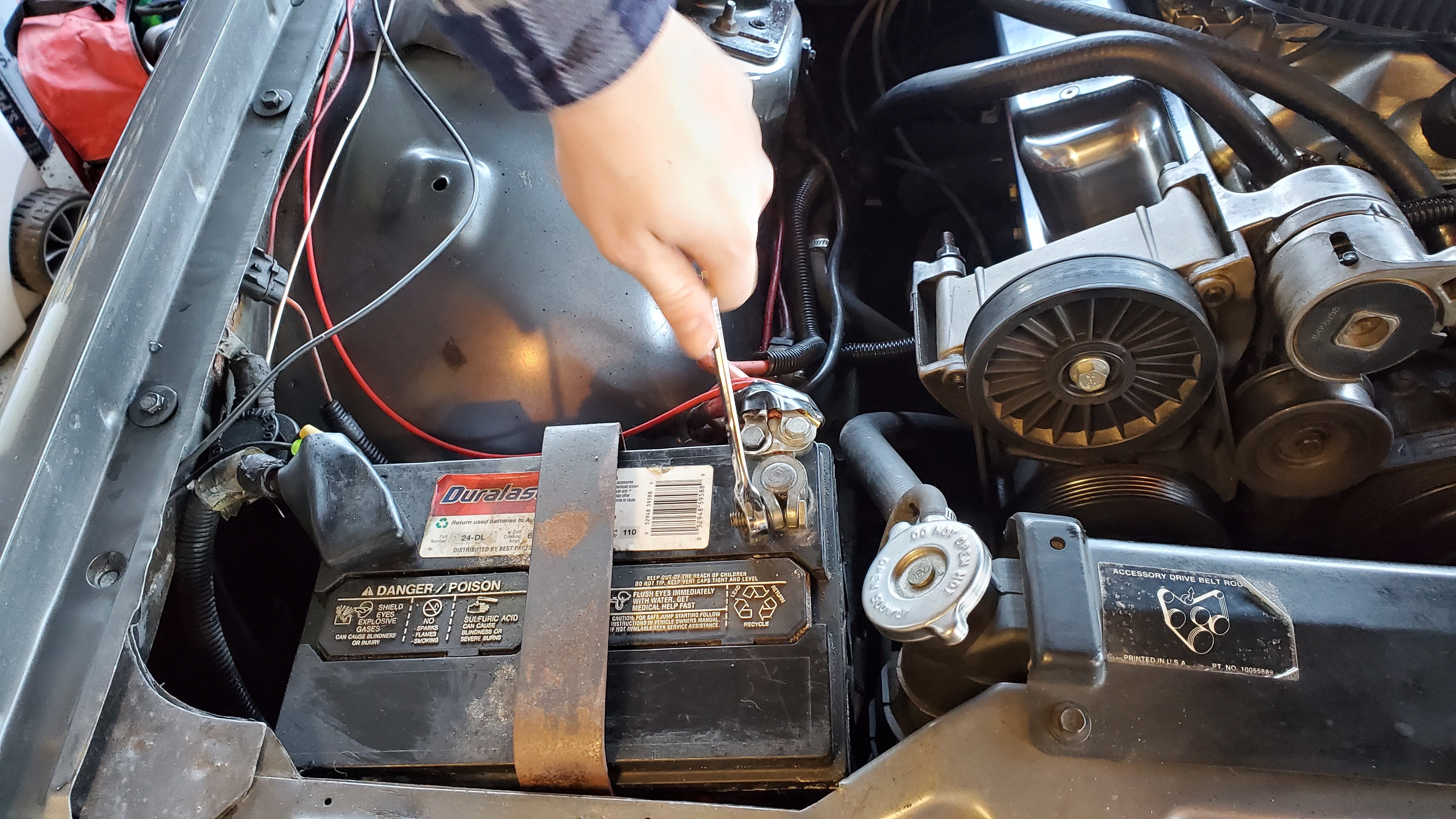
Don't forget to disconnect the battery! This important step helps you prevent damage to other electronics in the car or possibly start a fire.
Mounting the Two-step
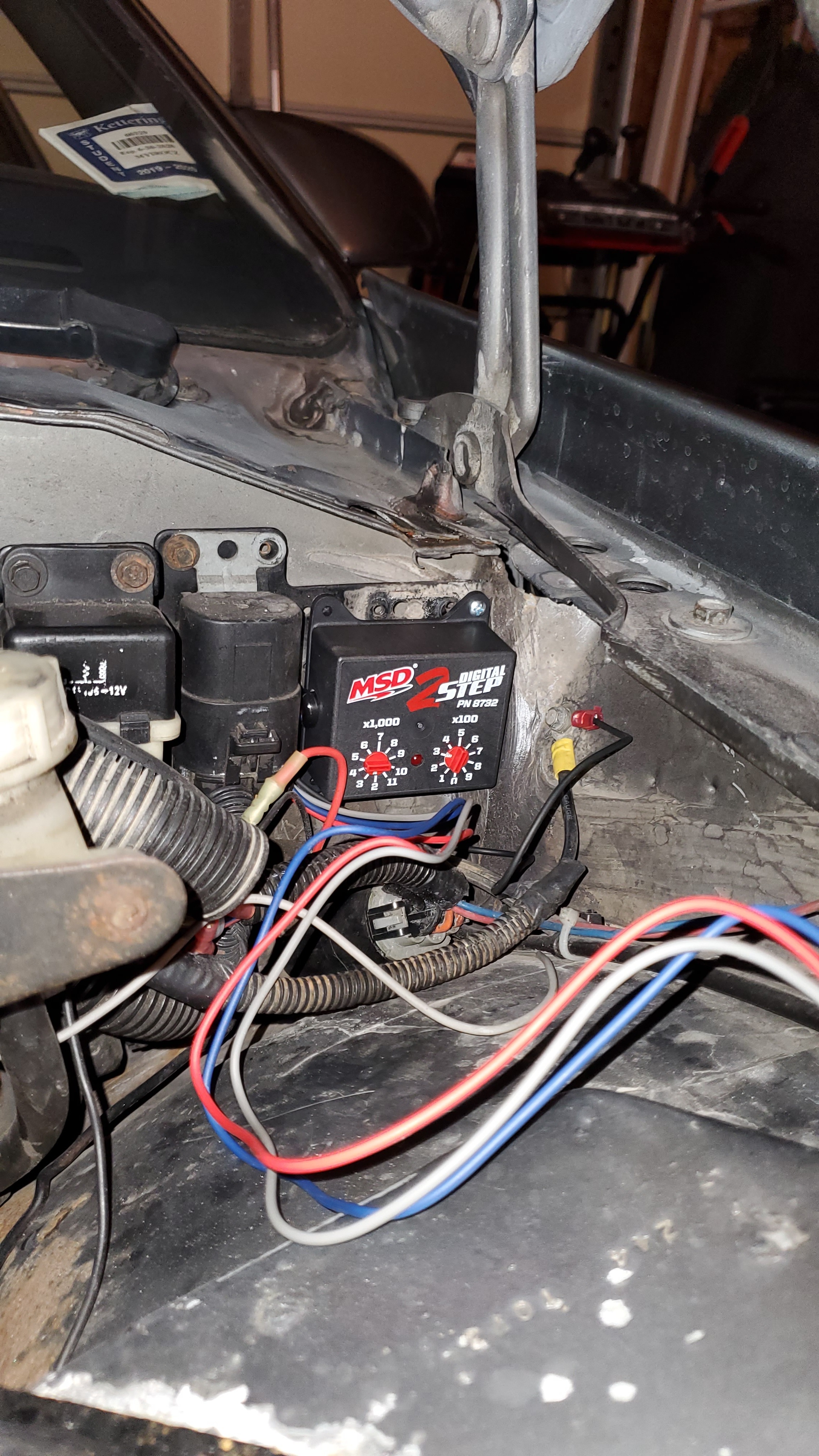
Find a suitable spot in the engine bay to mount the two-step module. It needs to be away from open heat sources like the exhaust manifold. An ideal placement for the box would be somewhere on the firewall, where the wires can easily reach where you plan to mount the switch. Using the included mounting screws, I mounted mine in the drivers' side corner of the firewall, next to the brake booster.
Locate the Tachometer Wire
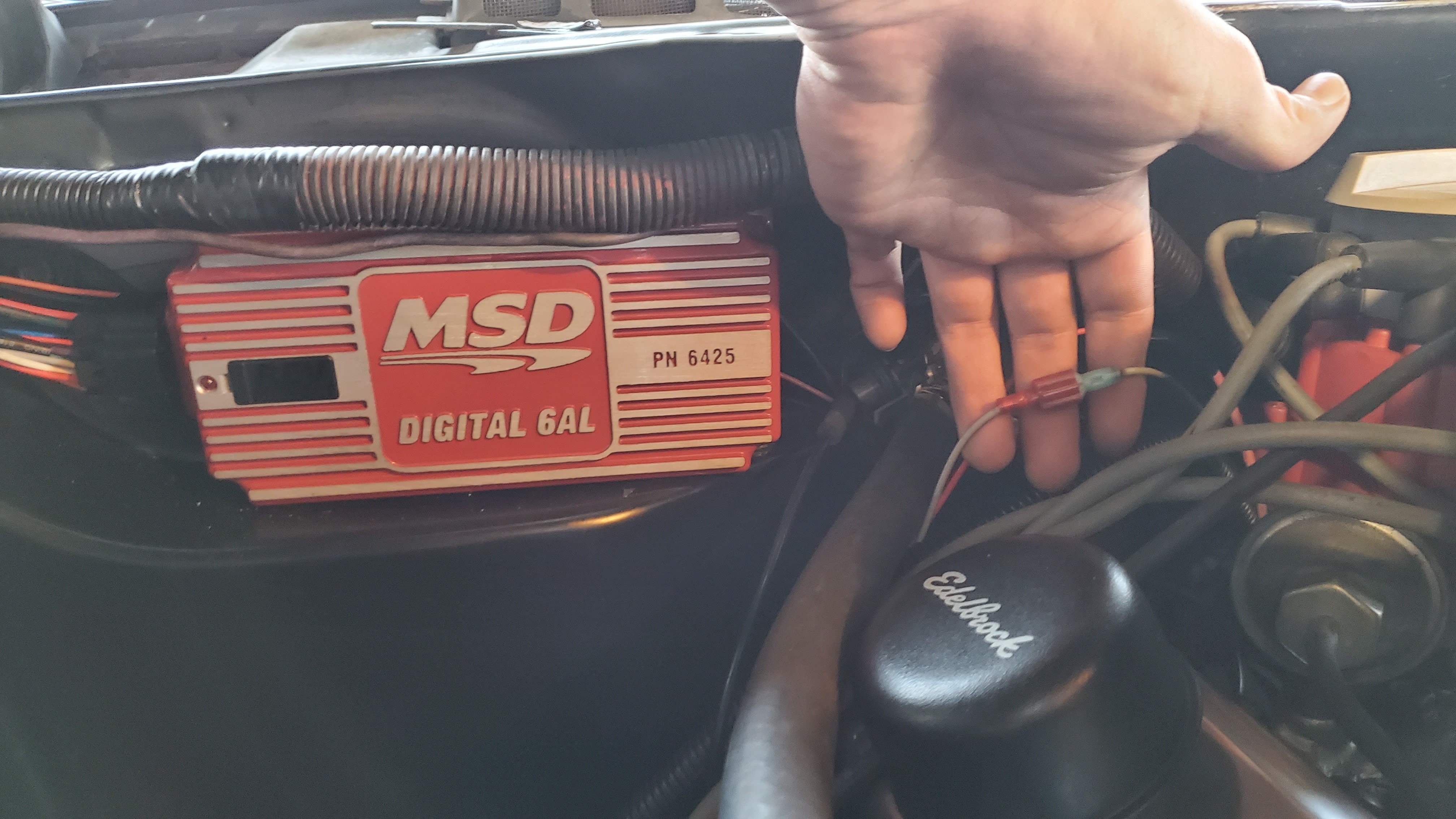
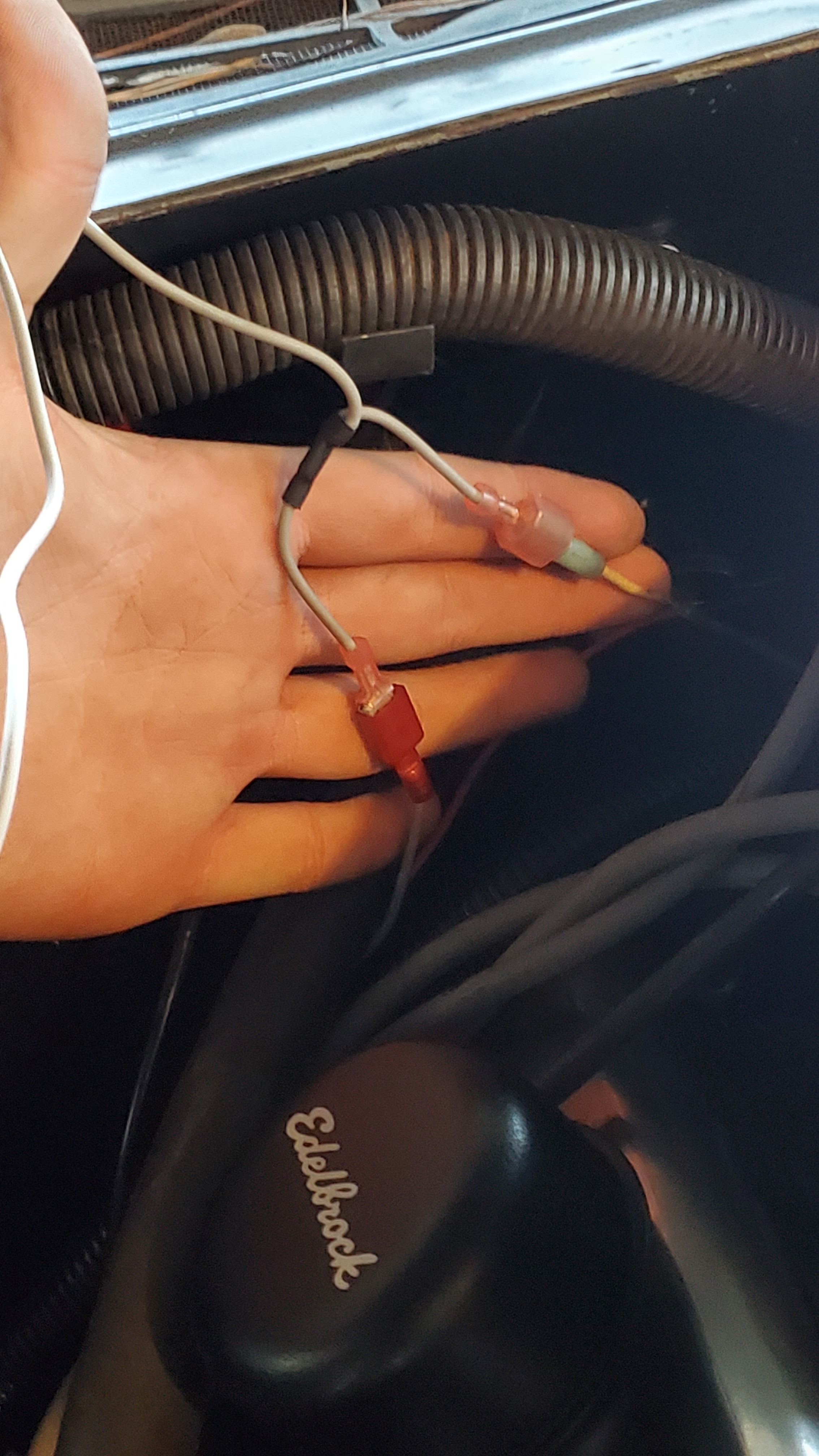
Locate the gray tachometer wire going from the 6AL to the gauge cluster. The gray wire from the two-step module will connect in the middle of this wire using the wire splitter that is included in the package.
Connect to Ground
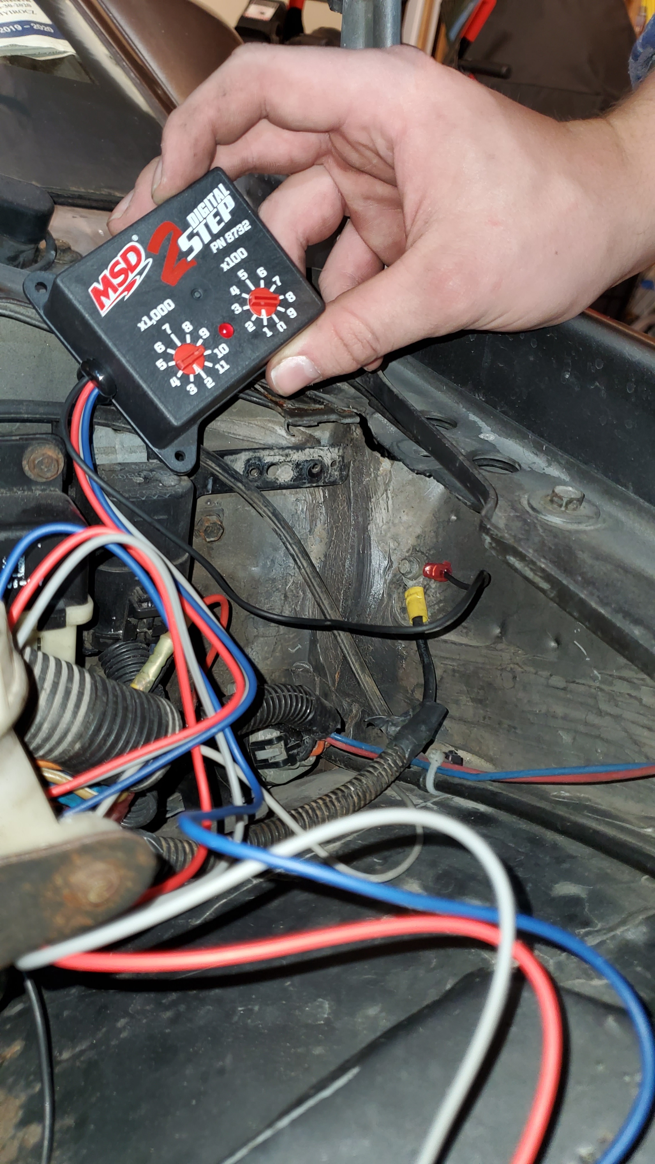
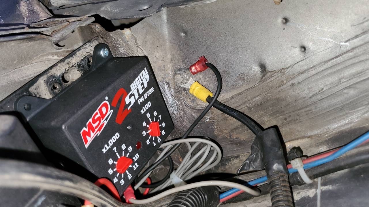
The black wire from the two-step needs to be connected to a nearby ground. If there are no existing ground locations within the reach of the wire, you can use a self-tapping screw to connect it to the frame. Using a pair of wire crimpers, crimp a ring terminal onto the black wire. Then you will be able to connect the wire to the grounding location. Make sure the wire is firmly secured to the frame to make a good connection.
Placement of Wires
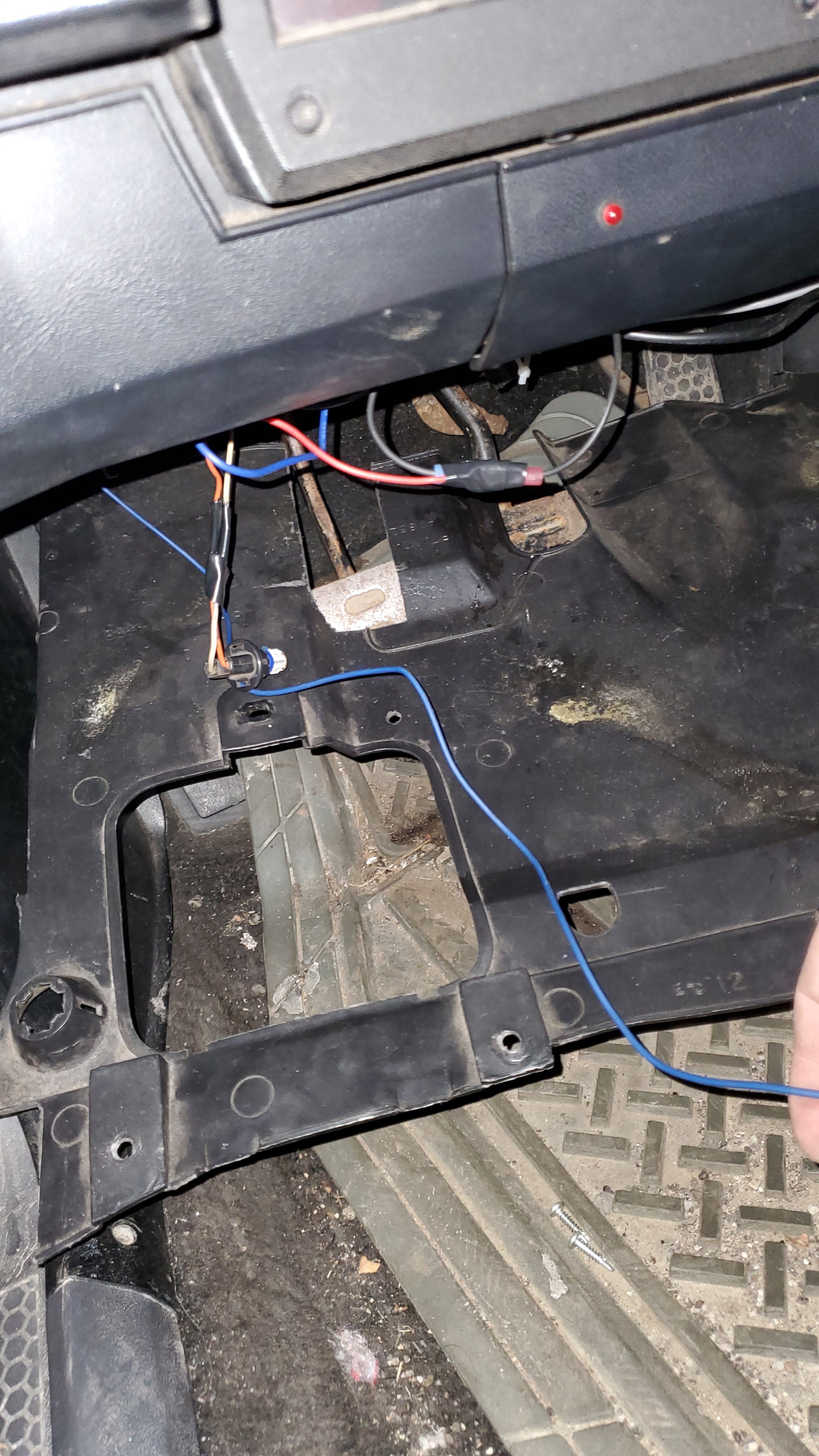
Feed the blue and red wires from the two-step through the firewall and under the dash.
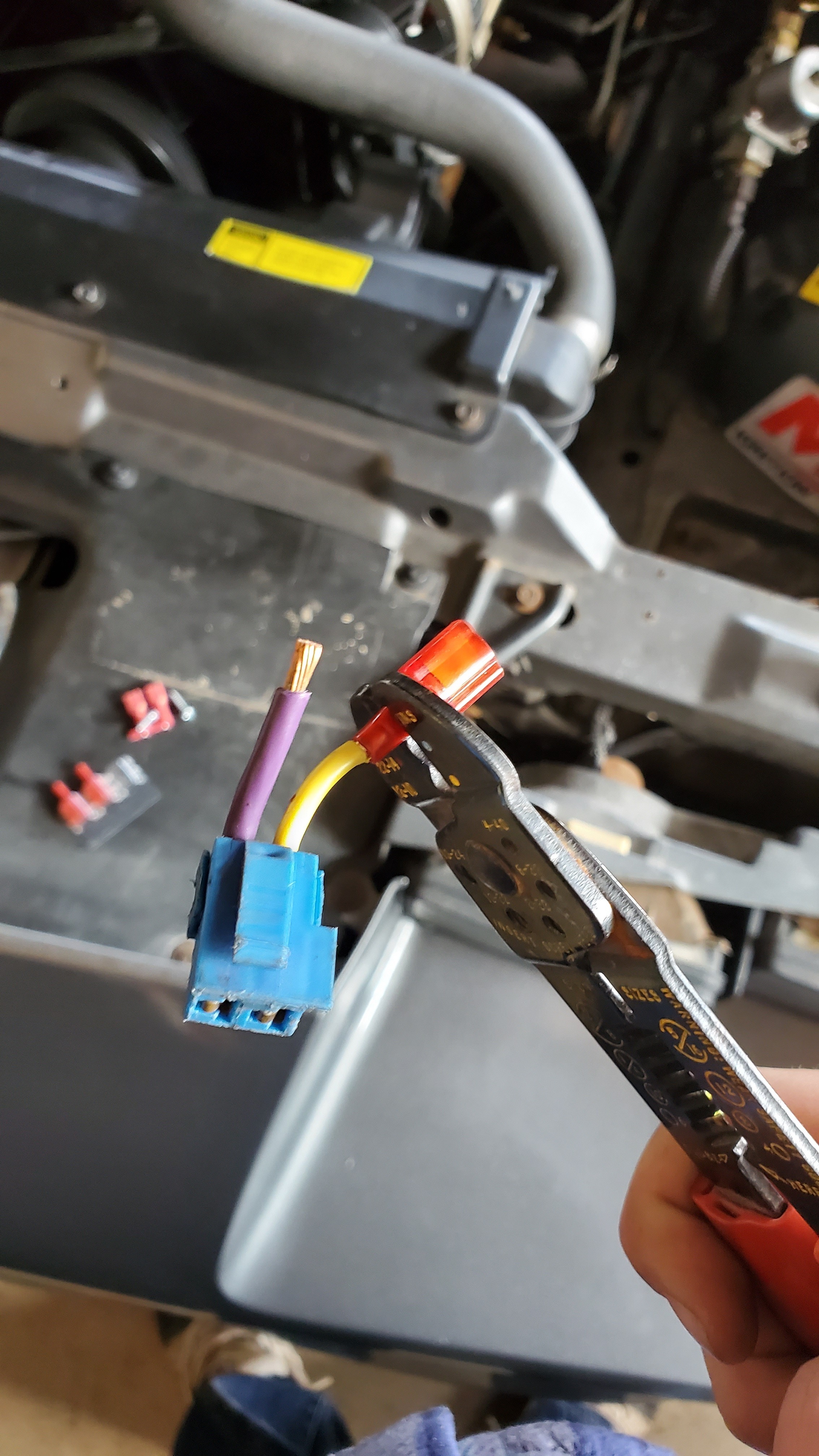
Connect male spade connectors on each wire of the clutch safety switch plug.
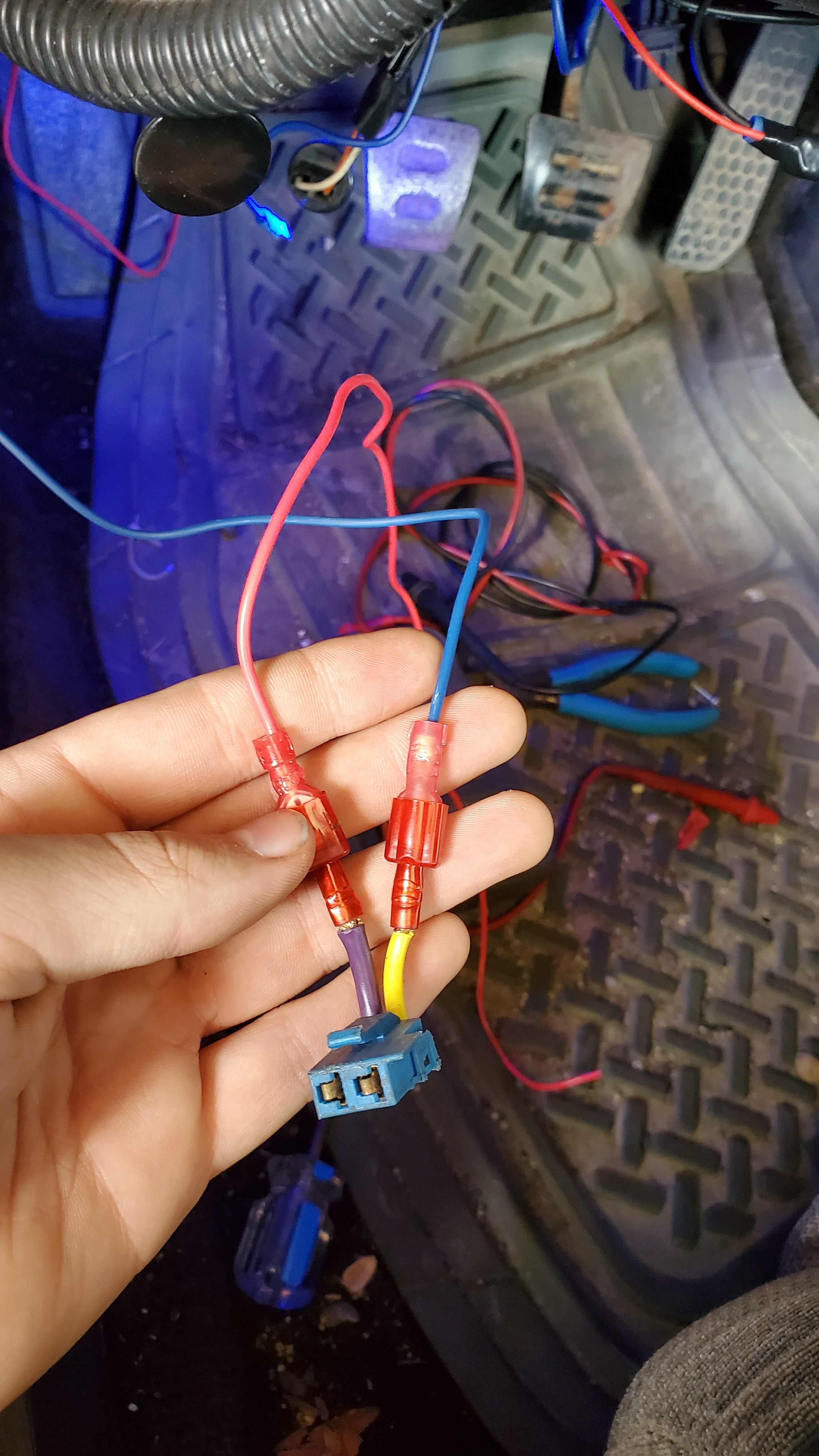
Using female spade connectors, connect the blue wire to one side of the clutch safety switch plug, and a new wire to the other side. After connecting these two wires, you can plug it back in to the clutch safety switch behind the clutch pedal.
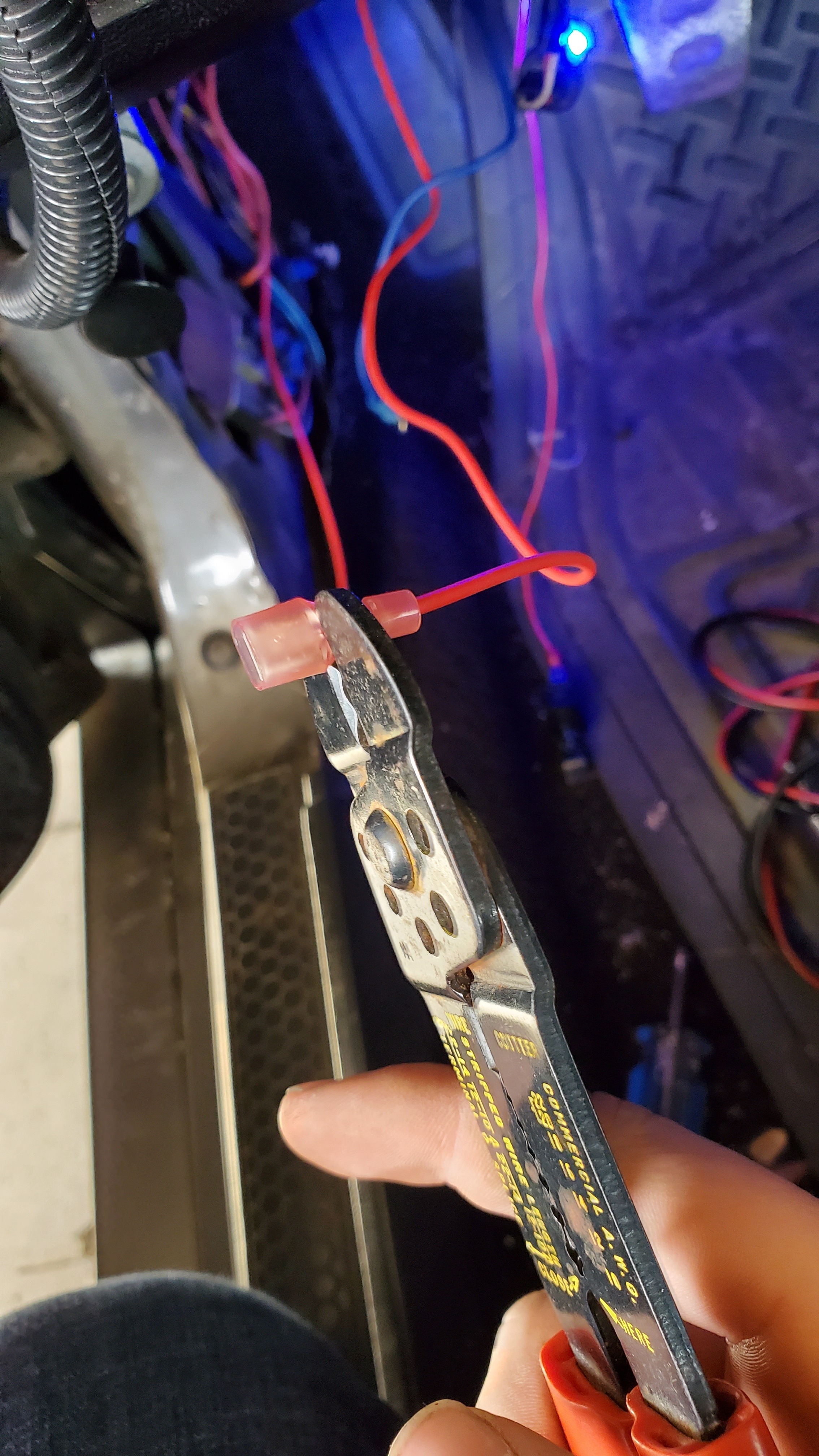
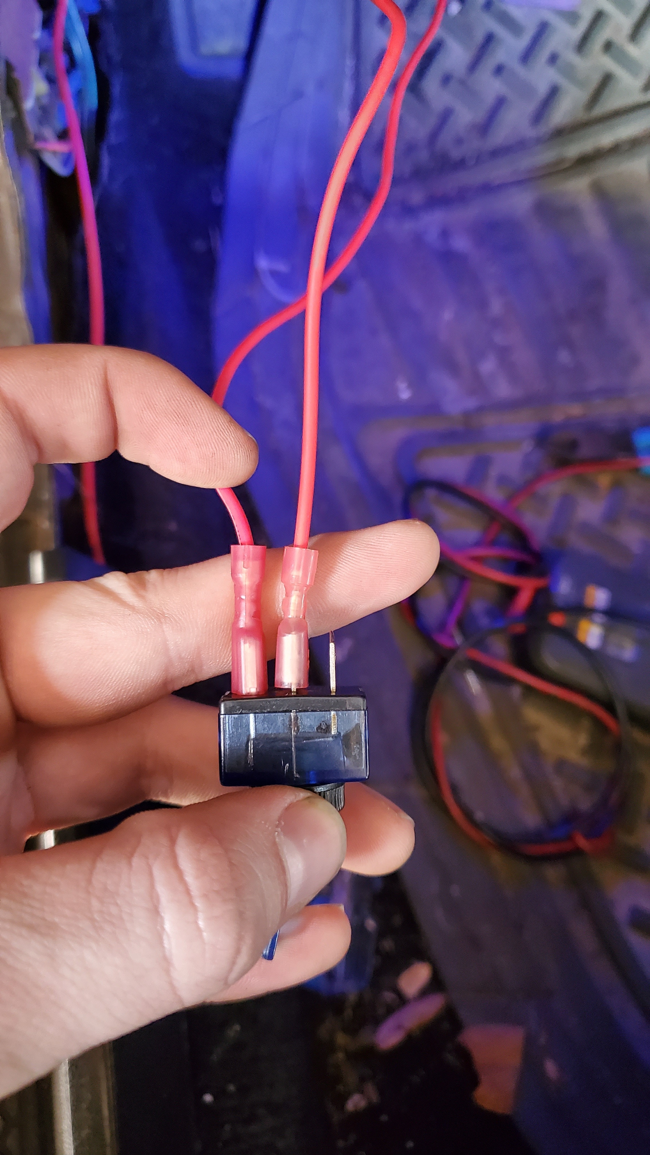
Next, crimp a female spade connector onto the other end of the wire from the clutch switch and on the end of the red wire from the two-step box. The wire from the clutch switch is plugged into the leftmost pin of the toggle switch, and the red wire from the two step box is plugged into the middle pin.
Find a Power Source
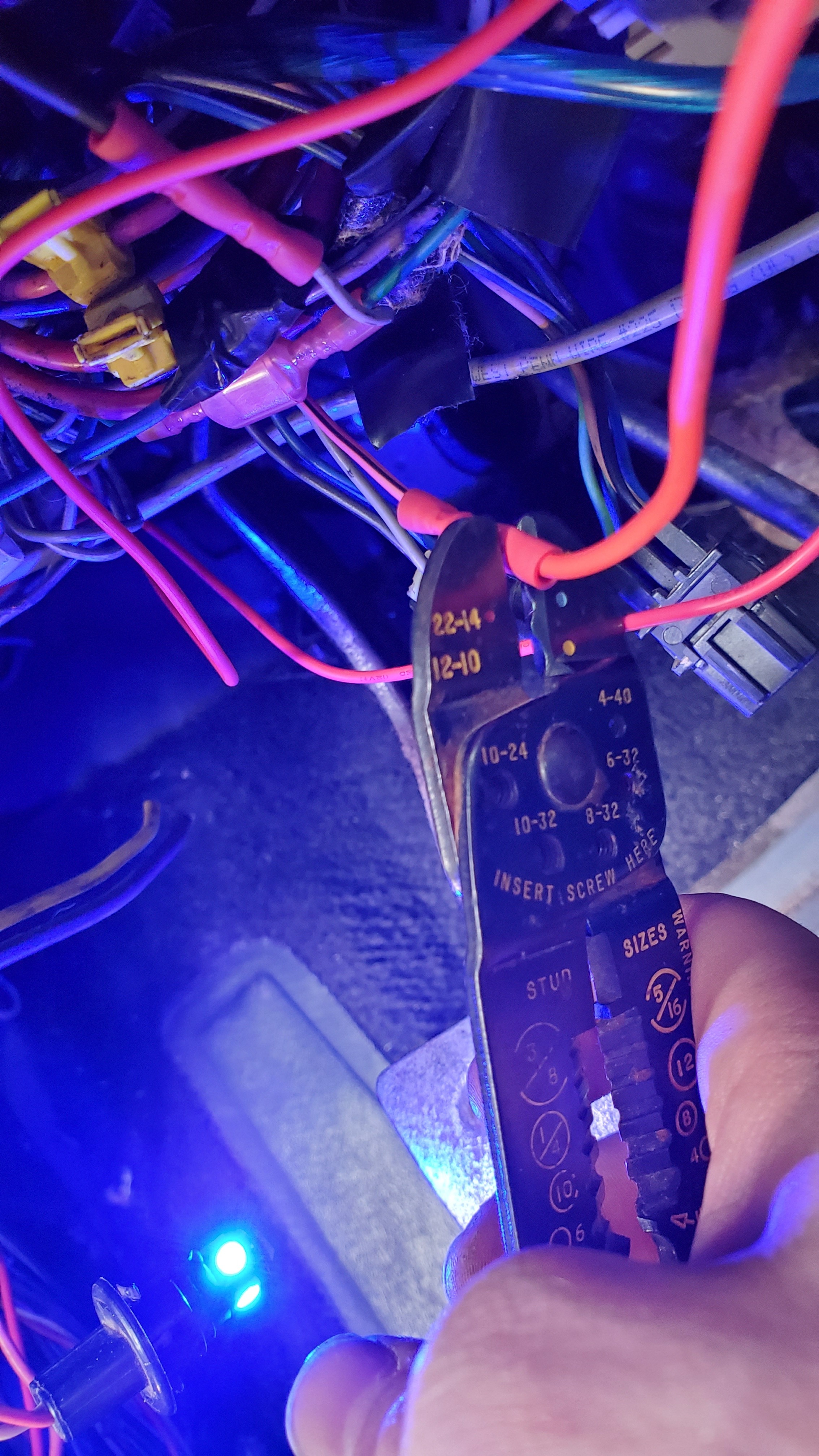
The last wire for the switch needs to be ignition power. This wire will receive 12V when the car is on, but no power while the ignition is off. I used the power wire from my old cruise control unit, but you can use any wire that is controlled by the ignition. Using a butt splice, connect an extra wire to the ignition power wire.
Connecting Power to the Switch
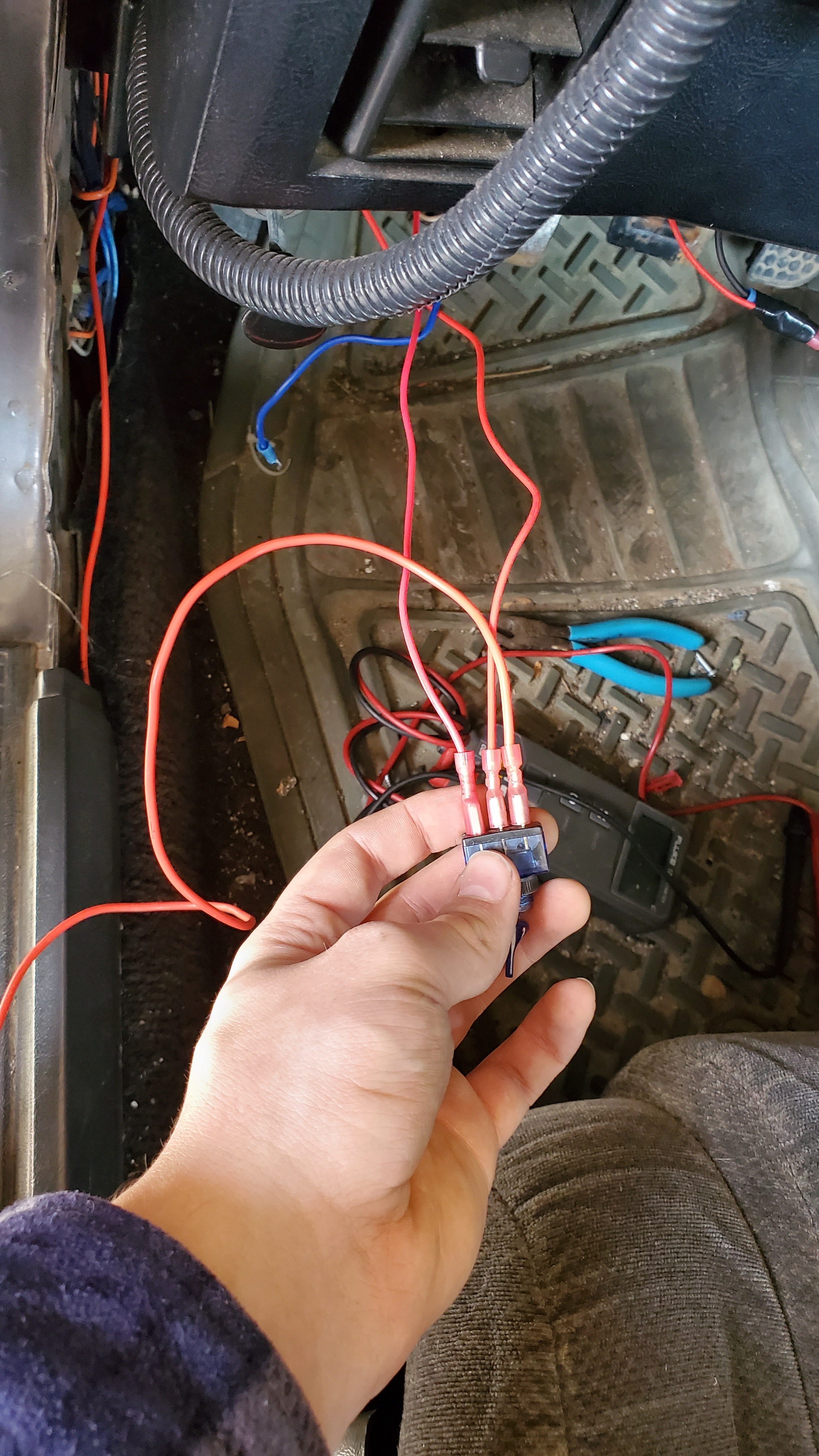
Crimp a female spade connector onto the end of the wire you just added, and plug it into the rightmost pin on the toggle switch. This will introduce power into the circuit and power the two-step module.
Mount the Switch
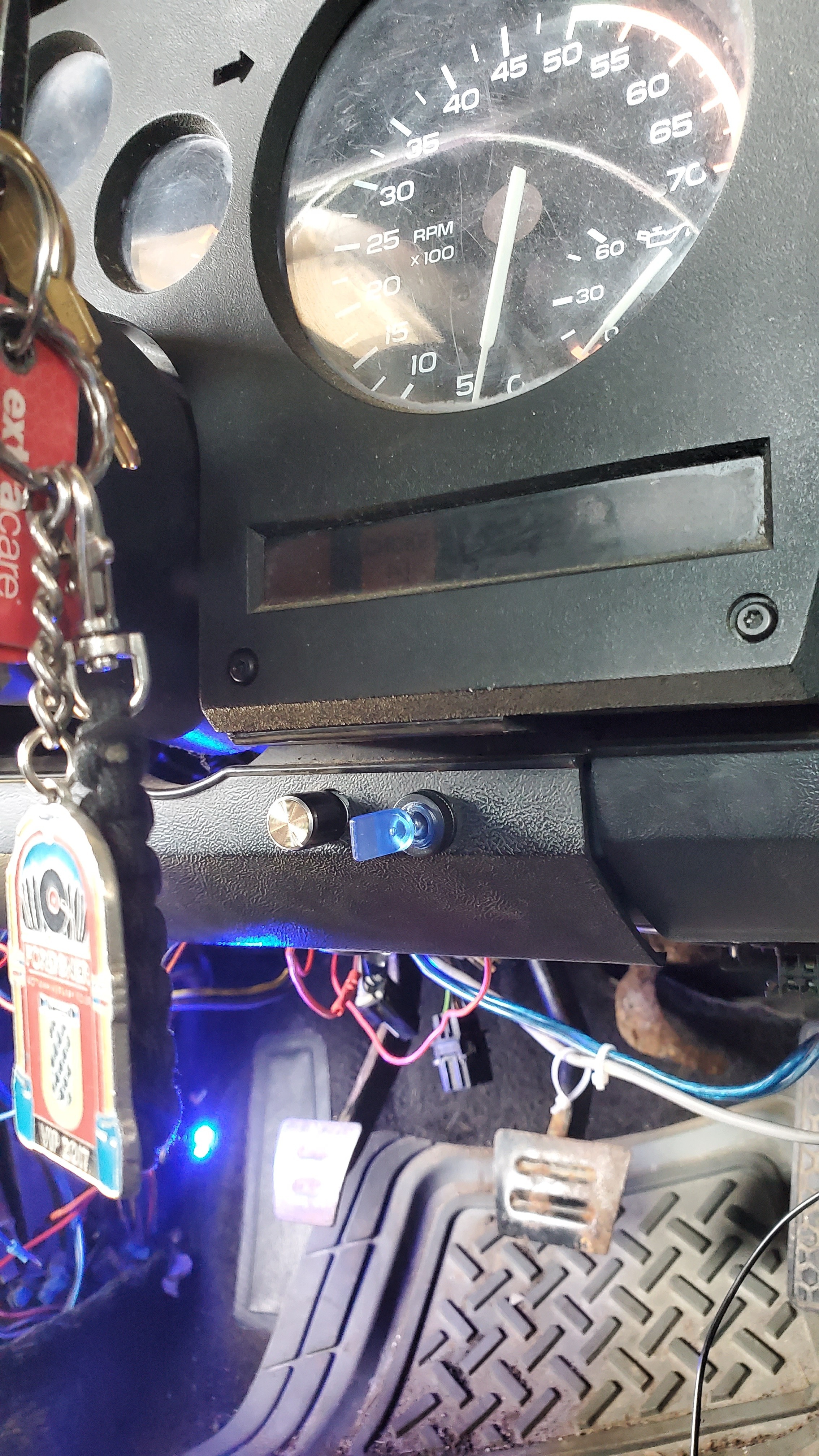
Now that you have all of the wires connected to the switch, you can mount it wherever you choose. I mounted mine on the bottom side of the gauge cluster. This switch will allow you to enable and disable the two-step from activating.
Testing the Two-Step
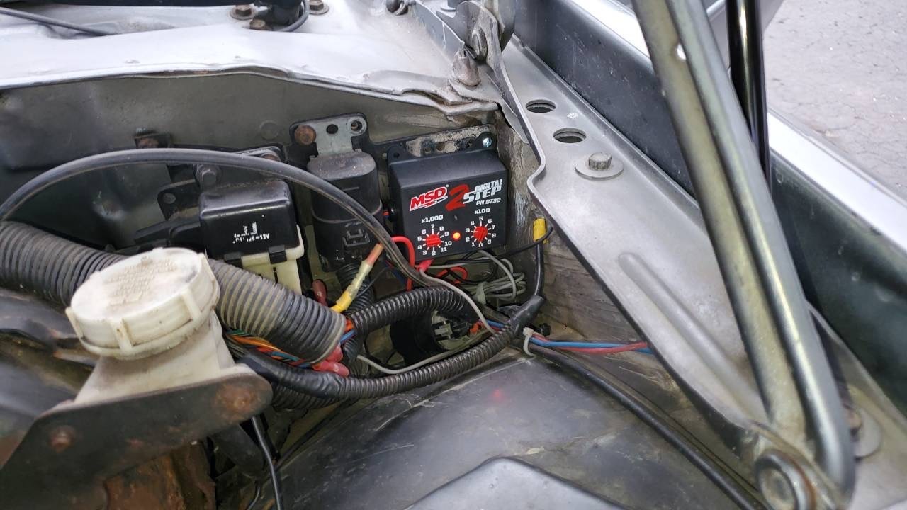
Next, reconnect the battery. Now, whenever the toggle switch is ON and the clutch is depressed, the LED on the two-step box will illuminate. If there is no light when those conditions are met, check and make sure that your wires are connected properly and it is getting 12V of power.
Adjusting the Rev Limit
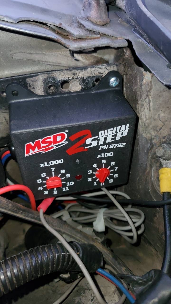
Using the two dials on the front of the two-step box, you can choose what RPM you want to limit the engine at. Turn the dials to select your desired limit, turn the toggle switch on, and depress the clutch pedal. If it is functioning properly, the engine will stay at the desired RPM when the gas pedal is pushed down.
Outcome
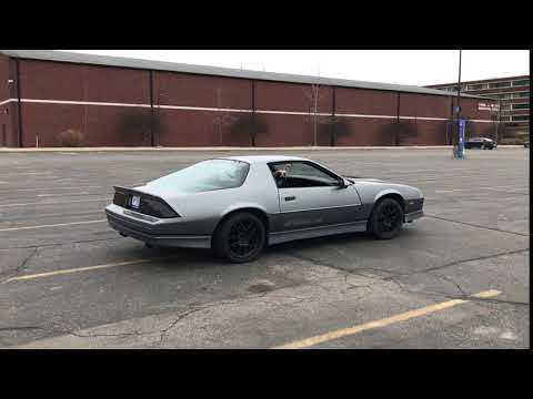
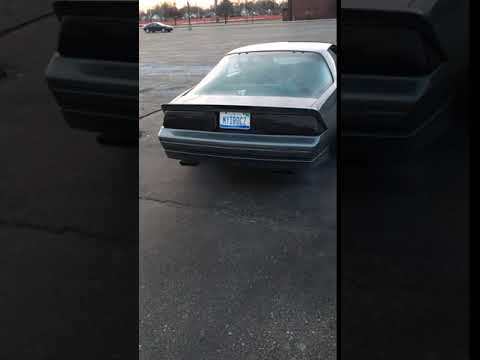
Attached to this step is a video of me launching without the two-step vs. with the two-step engaged. Hopefully after this installation, your launch times will improve and leave your opponents in the dust! :D
The other attached video is of the backfire. It backfired here because the two step was doing its job. The two step is designed to stop spark going to the engine to hold it at a certain RPM, but it does not control fuel. Because of this, it is possible for the engine to dump excess fuel into the exhaust pipes, which can be ignited while in the pipes, creating a big bang sound and flames from the tailpipes. While this looks cool, its probably not the best for your exhaust system.