MQTT Manager, Lora and Lora 'Poor Man' Gateway - Super Cheap
by Fab64 in Circuits > Arduino
5673 Views, 7 Favorites, 0 Comments
MQTT Manager, Lora and Lora 'Poor Man' Gateway - Super Cheap
This project idea first came into my head when I got my very first electric car, which is usually parked in my condo's garage, 5 floors below my apartment, one floor underground.
Anytime I get home, I have to recharge the car which takes up to 10 hours to get to a full battery. I don't use it every day, hence when charged, I can either leave it connected to the power line (wasting some power and getting the charger warm) or I have to go down to the garage and disconnect it (wasting some time). For sake of completeness, I have to add, that I know that the car is fully charged because I receive a push notification to my phone via the application provided by the car manufacturer.
Since I am lazy and I don't want to waste energy, I needed something to switch off the power to the car charger without getting to the garage.
At first, I had thought about building a simple device to control the mains line via a relay and controlling that device remotely using my Arduino Manager iOS/macOS application (Arduino Manager). Unfortunately, my Wi-Fi router's signal does not reach down in my garage.
Then, I came up with a solution: using two LoRa modules which can easily transmit data from my apartment to the garage. I should have designed and built two devices: one with a relay to control mains and the other with a switch, each one connected to a LoRa module. But I would have lost the possibility to control the mains when not at home.
LoRaWAN would had been the solution, together with The Things Network for remote access, but this would have meant buying and installing a LoRaWAN gateway and learning how to set it up.
Therefore, I came up with a way cheaper solution which uses another one of my apps: MQTT Manager (MQTT Manager for iOS / MQTT Manager for macOS)
Supplies
- 2 x ESP32 devices. You can find them on Amazon for a few dollars. The basic model (ESP 32 Dev Module) without bells and whistles is enough for this project
- 2 x LoRa Modules SX127x (see article for details)
- A couple of bread boards to mount the prototypes
- 330 ohm resistor 5% 1/4W
- 470 ohm resistor 5% 1/4W
- Tactile Button
- Some male-male jumpers
- Some male-female jumpers
The Architecture
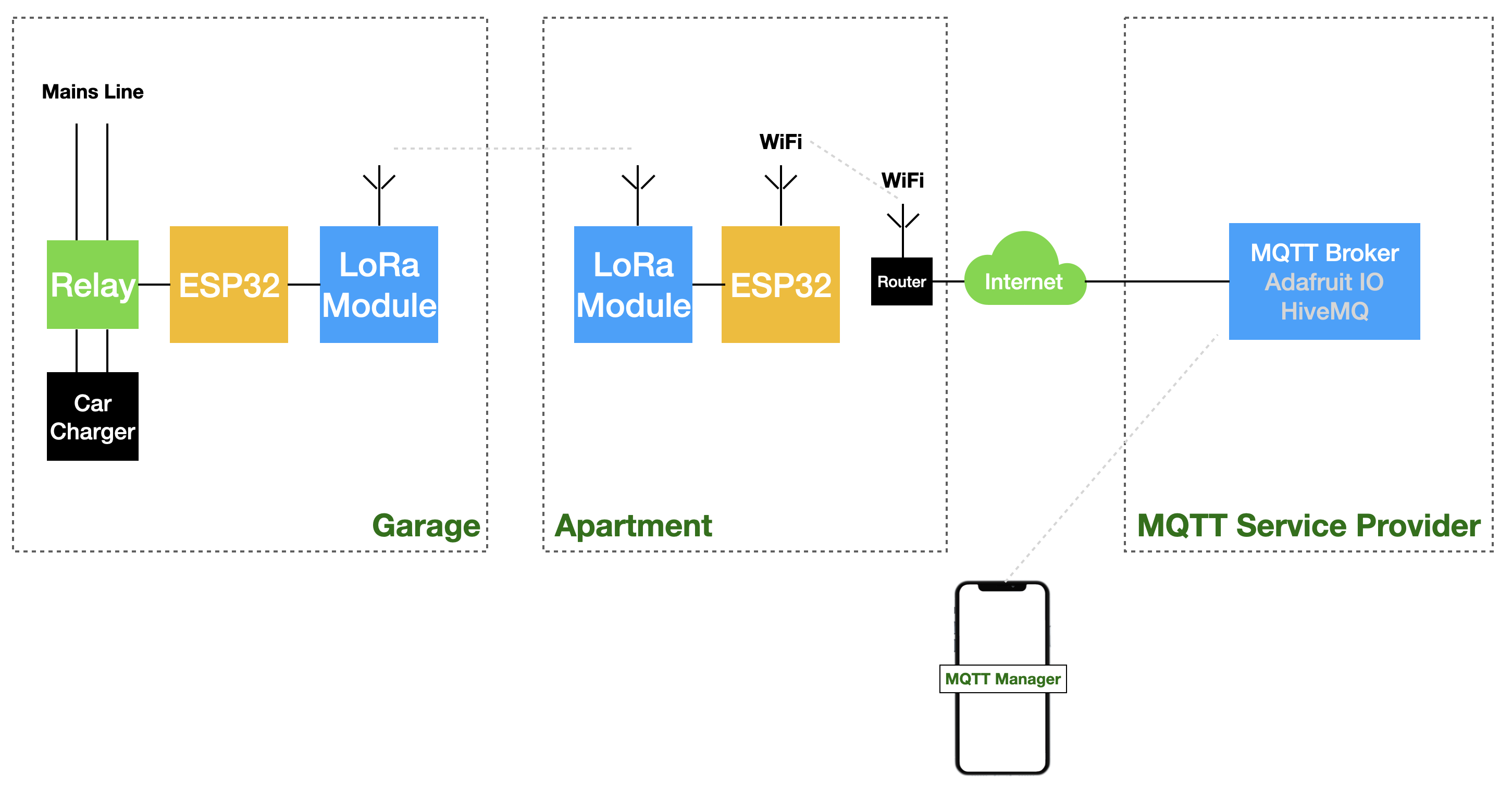
Garage
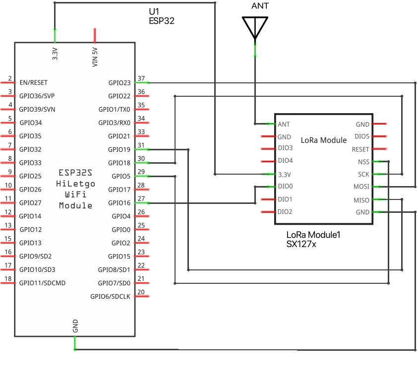
Here we have a simple device based on the ESP32 microprocessor wired to a SX127X LoRa module. There are various types of LoRa modules. I chose a module based on the Semtech SX127x chip, which you can easily buy on Amazon. There are various types of modules which differ in transmission frequency. You have to choose the module which suits the frequency allowed in your own country (see Frequencies by country).
Apartment
Here we have an ESP32 microprocessor wired to another SX127X LoRa module. The only purpose of this device is to route data. Data are received (via Wi-Fi) as MQTT messages and later transformed to LoRa messages to be transferred to the Garage device. Similarly, data received from the Garage device are transformed in MQTT messages and transferred to the MQTT broker.
The actual device in my garage doesn't need to transfer data to the gateway, it only has to receive an on/off command, but for the purpose of this tutorial I added a simple tactile button to show you how to send data.
To be clear, this 'Poor Man' Gateway doesn't compare at all with a LoRaWAN gateway in terms of standards, speed and reliability. But, since it is very cheap and the code is designed to easily handle other devices with different configurations - I think it's worth a try.
MQTT Broker
This is a service which essentially transfers messages with the connected devices and stores them (more info here: MQTT). Since this service is accessible through the Internet, I can use my MQTT Manager application on my iPhone to switch the mains line off when the car is fully charged no matter where I am.
Preparing the Arduino IDE
In order to compile the provided code, you have to use the Arduino IDE which is available for free (Download). Once you install it, you have to follow these steps:
- If you haven't already, you have to install the additional software for ESP32 (see here)
- Install these two additional libraries:
- Open the Arduino IDE
- Sketch -> Include Library -> Manage Libraries ...
- In the search field type MQTT Client
- Select the library provided by Joël Gähwiler
- Click Install
- When the installation completes, enter LoRa in the search field
- Select the library provided by Sandeep Mistry
- Click Install
Now you are ready to upload my code, but before that you have to configure the MQTT Broker Service.
HiveMQ Service Configuration
For the broker you can use one of the free available services (with some limitations which have little or no impact on this project) like Adafruit IO or HiveMQ. You can even use a local broker running on your own server or Raspberry PI.
The MQTT Manager documentation shows you how to configure a local Mosquitto broker on various platforms (see here).
For this project I have used HiveMQ broker. To configure it, follow these steps:
- Go to HiveMQ MQTT Cloud Broker
- Click Sign up now to create a new user
- When asked, verify the account via the e-mail you received. You will be redirect to the login page
- Log in
- You will be redirect to the Getting Started tab where you can create the credentials for the Garage Device.
- Enter the following information (you can choose whatever you like, this tutorial is easier to follow using the same values. Keep in mind that you can change them later on)
- Username: goofy
- Password: Goofy01@
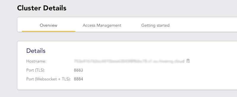
- Switch to the Overview tab. The information in the page will be used later in the tutorial.
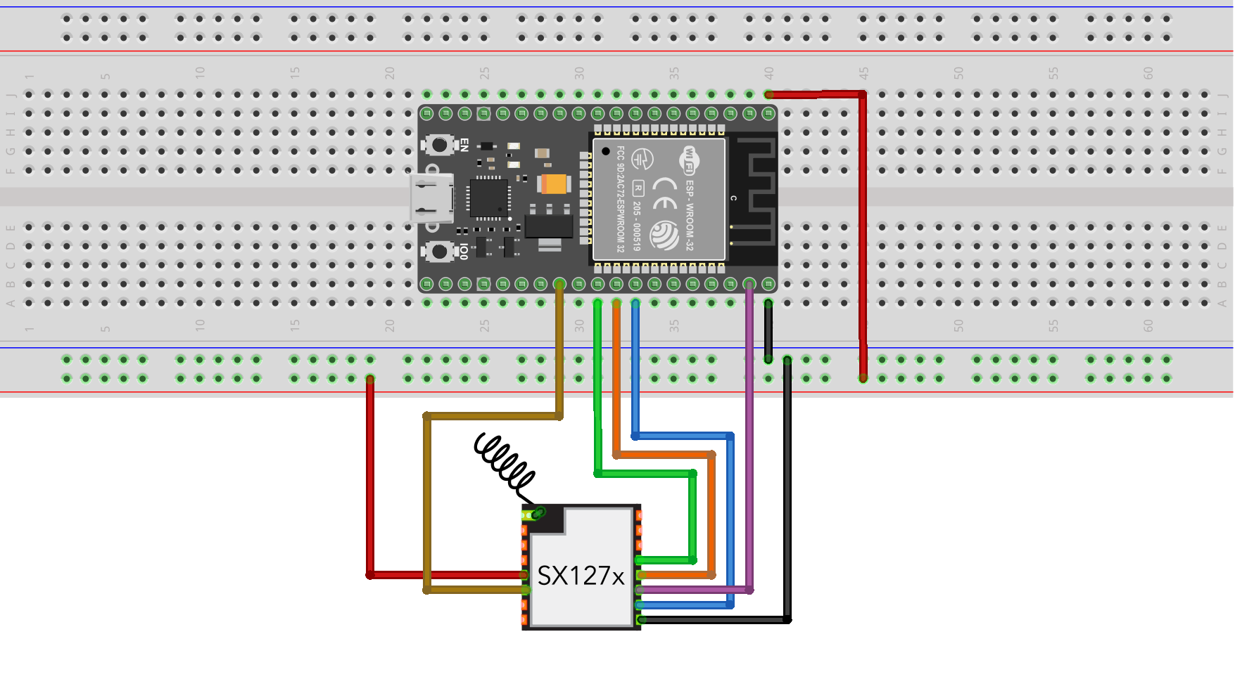
Building the Garage LoRa Device
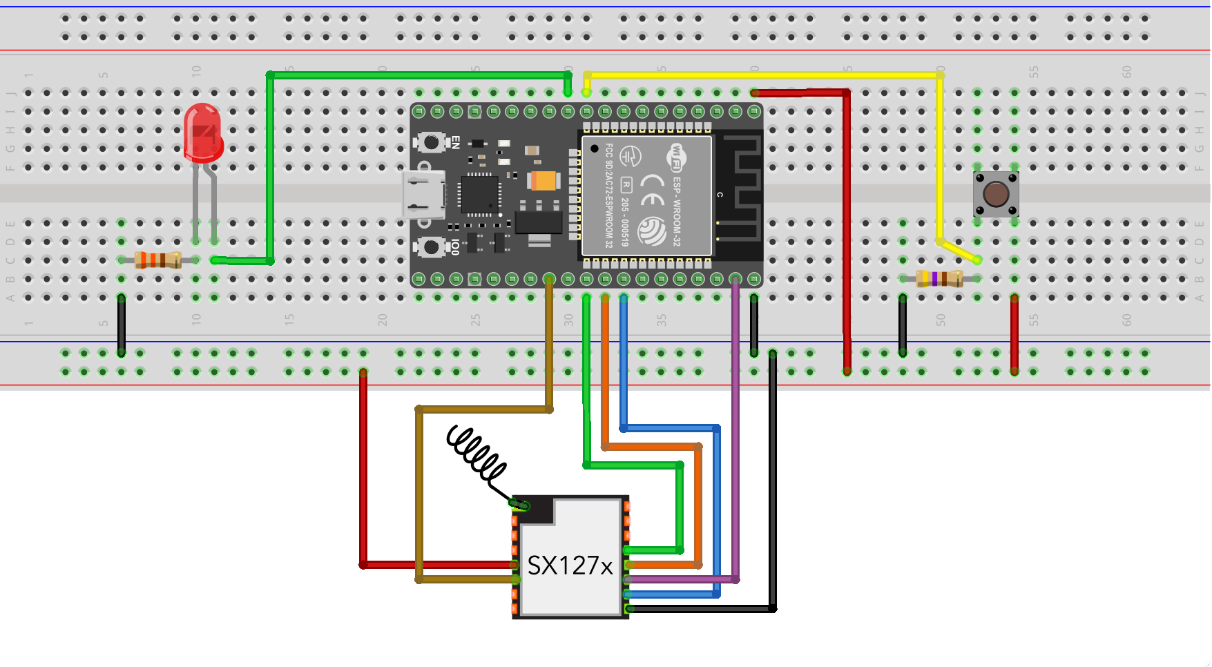
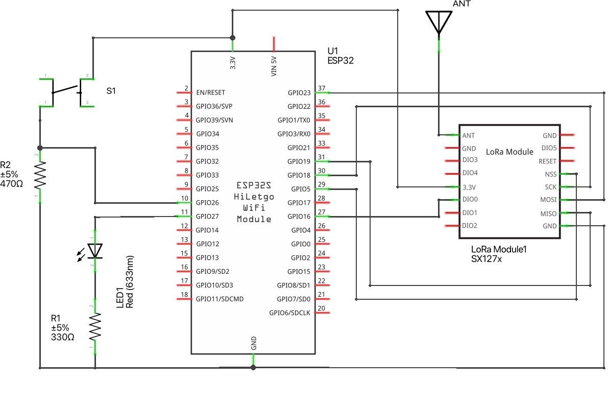
As I have already mentioned, the device is very simple. The previous pictures show the schematic of the device and how to mount it on a breadboard.
To keep this tutorial simple (and not dangerous!), I have replaced the circuitry to control the relay with a simple LED and for learning purposes, I have also added the tactile button to show how to transfer data from this device to the MQTT broker and eventually to your mobile phone.
Powering the device
Usually IoT devices are powered with small (rechargeable) batteries and the hardware and software design have to be very accurate. This is to minimize the power consumption in order to make the battery last as long as possible.
In this case, I have the mains line available and the device is powered using a wall adapter with an output of 3.3V, 1A.
Uploading the Device Code
- Download the attached file: ESP32_LoRa_Device.ino
- Open it with Arduino IDE
- You have to adapt the code to your own LoRa Module frequency. Locate these lines:
// initialize radio at 868 MHz
if (!LoRa.begin(868E6)) {
   Serial.println("LoRa init failed. Check your connections.");
   while (true)
      ;
}- Replace 868 with the frequency of your device (169 MHz, 315 MHz, 433 MHz, 868 MHz, 915 MHz)
- Connect the device to your computer and upload the code
- Open the serial monitor
- If you read 'Device Ready', the device is up and running
Roughly speaking, when the device receives a payload
- S=1, it turns on the LED
- S=0, it turns off the LED
and it transmits a payload:
- B=1, when the button is pressed
- B=0, when the button is released
Downloads
Building the 'Poor Man' Gateway
Building the Gateway is very simple and you can refer to the schematic for all the details.
Side Note
If you need to actually use the Garage Device and the Gateway, the breadboard is not an option. You have to build them using a Perforated Board or design your own PCB.
Uploading the 'Poor Man' Gateway Code
Uploading the Gateway code is a little bit more complicated, because you have to configure some parameters specific to your environment.
- Download the attached file: ESP32_LoRa_Gateway.ino
- Open it with Arduino IDE
- First, you have to configure the connection to your Wi-Fi network. Locate these lines:
const char ssid[] = "[Your WiFi network SSID]";
const char pass[] = "[Your Password]";
and replace with the values of your Wi-Fi network
- Then, you have to configure the connection to the HiveMQ service. Locate these lines:
#define BROKER_ADDRESS "[MQTT Cluster Hostname]"
#define BROKER_PORT 8883
#define BROKER_USER "goofy"
#define BROKER_PASSWORD "Goofy01@"
and replace the [MQTT Cluster Hostname] with the hostname that you find in the HiveMQ overview tab. (See picture).
You can leave other values unchanged or adapt to what you have entered in step #3.
- Lastly, you have to adapt the code to your own LoRa Module frequency. Locate these lines:
// initialize radio at 868 MHz
if (!LoRa.begin(868E6)) {
   Serial.println("LoRa init failed. Check your connections.");
   while (true)
      ;
}
Replace 868 with the frequency of your device (169 MHz, 315 MHz, 433 MHz, 868 MHz, 915 MHz)
- Connect the device to your computer and upload the code
- Open the serial monitor, if you read the following messages the gateway is up and running, otherwise double check the parameters you entered.
Connecting to WiFi ........ connected!
Connecting to MQTT Broker ... connected!
Gateway Functioning
When the gateway receives a payload (e.g. B=1) from the device with address 0xAB, it writes to the topic:
LoRa/[Device Address]/[Device Output Property]
the received value. Hence, it writes 1 to the topic:
LoRa/ab/B
For each Input Property of each device, the gateway subscribes to the topics in the form:
LoRa/[Device Address]/[Device Input Property]
in order to receive commands from the broker and route them to the device to which they are intended to.
In this case the topic is:
LoRa/ab/S
Hence, when the topic changes to 1, it sends a LoRa message to the device with address 0xAB with this payload:
S=1
Downloads
MQTT Manager Configuration
Now we are ready for the last step: configuring MQTT Manager to connect it to HiveMQ.
- If you have not already installed MQTT Manager, you have to do that:
- Open the App Store
- In the search field enter MQTT Manager
- Select the app and install it as usual
- Download the file LoRa Garage Device.txt
- Rename it LoRa Garage Device.mmwl
- Send it by e-mail to your own address
- Open the received e-mail, click the file and open it with MQTT Manager
- Open the side menu (iPhone/iPad only)
- Select Scenes
- Select LoRa Garage Device
- Open the side menu (iPhone/iPad only)
- Select Connections
- Select and edit HiveMQTT for LoRa Gateway
- Replace Hostname with the hostname that you find in the HiveMQ overview tab and click Ok
- Open the side menu (iPhone/iPad only)
- Select Widgets
- Connect to the broker clicking on the plug icon at the bottom side of the screen
- If the blue LED turns on, you are good to go
Side Notes
You can create the Scene and the Connection yourself. See the MQTT Manager documentation on how to do that
Downloads
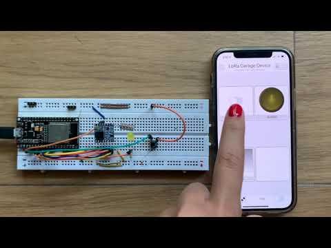
Final Test
We are eventually ready to test everything.
- Double check that both the LoRa Device and the Gateway are powered on
- Double check that both the LoRa Device and the Gateway are properly connected as shown in the previous steps
- Double check that MQTT Manager is connected to the broker. The blue LED at the bottom side of the screen should be on. Otherwise click on the plug icon to connect it
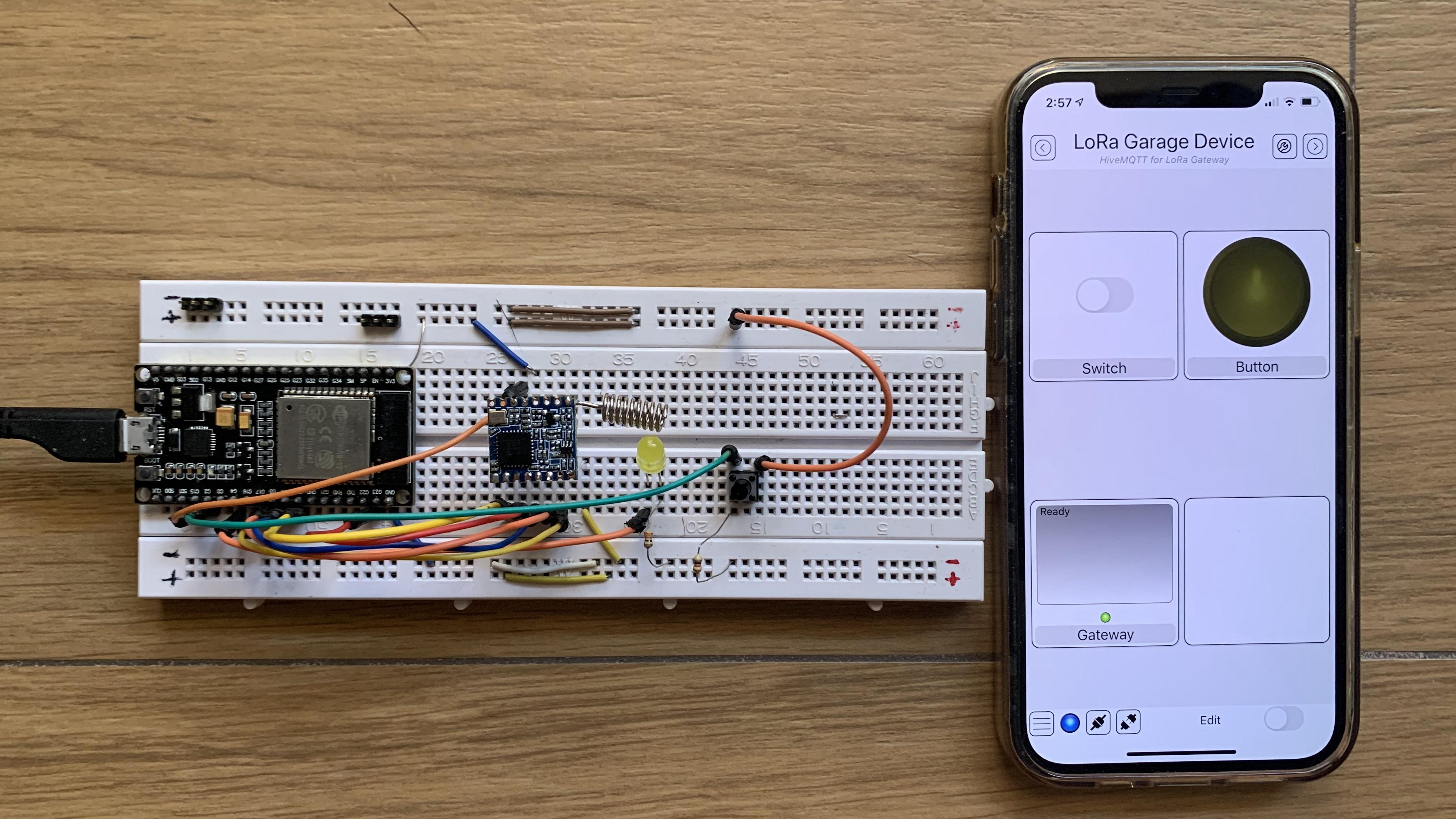
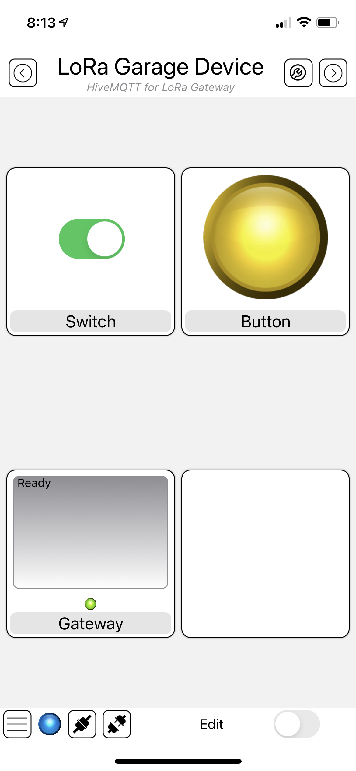
- Click on the Switch Widget named Switch
- After a few seconds the LED on the LoRa Devices should turn on
- Click again on the Switch Widget and the LED on the LoRa Devices should turn off
- Press the button on the LoRa Device and keep it pressed
- The yellow LED on MQTT Manager should turn on
- Release the button and the yellow LED on MQTT Manager should turn off
Congratulations! You have set up a LoRa Device and a simple LoRa Gateway. Starting from this base setup you can create more complex devices with more input and output properties and even add more devices.
Conclusions
With this simple and cheap setup I am able to turn off the car's charger just opening MQTT Manager on my iOS device.
Demo
Security Considerations
Just a quick word about security. LoRa radio transmits data unencrypted and they can be received by any device. That being said, anyone can also send commands to your Garage Device to turn on and off the LED.
This is not a problem for my own project. At most, I will find my car not charged in the morning.
This issue can be overcome using encryption (e.g. AES128) like LoRaWAN protocol. That is not complex to implement (Let me know if someone is interested in it...).