MPU6050 Unleashed: How to Harness Motion and Orientation Data

by Dhrish Jain in Circuits > Arduino

108 Views, 3 Favorites, 0 Comments

MPU6050 Unleashed: How to Harness Motion and Orientation Data

MPU6050 Module.jpg

This guide will help you to know mpu6050 sensor works, how to use it and what challenges you will face while using it

WHAT IS MPU6050?

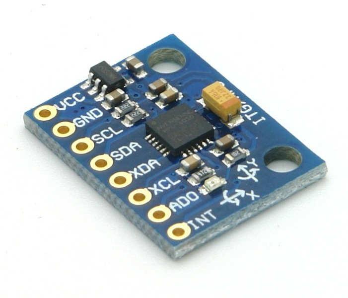
The MPU-6050 an IMU (Inertial Measurement Unit) sensor that helps us to measure motion and orientation of the object in which it is mounted. This 2cmx1.6cm board contains 3 axis accelerometer and 3 axis gyroscope. This also have DMP (Digital motion processor) which help us to perform complex calculation onboard rather than relying on microcontroller.

HOW IT WORKS?

MEMS-Accelerometer-Working.gif
Accelerometer-Animation-Labels.png

Let’s go one by one.

Accelerometer: -

You must have heard that accelerometer working is simply explained ball inside the piezoelectric walled box.

  1. Ball Inside piezoelectric box: -

Let me repeat it once again, when this box is accelerated the ball inside the ball hits walls and this create electricity which are nothing but analog signals and hence deduce in which direction the box is accelerated.

NOTE: -Readings or range of accelerometers are mentioned in g (G-force 1g is equivalent to gravitational acceleration 9.8 m/s2).    

Now let’s see how modern accelerometer works. They are based on MEMS (Micro-Electro-Mechanical System) this accelerometer is micro machined structure built on top of silicon wafer.
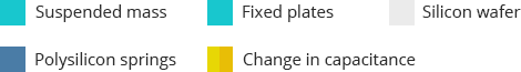
  1. MEMS Accelerometer: -

Credits for gifs and images: - https://lastminuteengineers.com/mpu6050-accel-gyro-arduino-tutorial/

In this structure when the force (here it is G-force is produced due to acceleration) is applied on the suspended mass the centre wiggling portion the capacitance between the fixed plate and moving plate of suspended mass changes accordingly as you can see in the picture. Then sensor processes this change and convert it to analog output voltage. Now simply placing these structures on 3 axis we can read acceleration in their respective axis


Gyroscope: -

Corioliskraftanimation.gif
MPU6050-Accel-Gyro-Working-Drive-Mode-Output.gif

Credits for gifs and images: - https://en.wikipedia.org/wiki/File:Corioliskraftanimation.gif

To measure angular rotation, we use gyroscope. They work on Coriolis Effect that says that when a rotating force is applied on a linear moving object a force is generated on object perpendicular to the velocity and to the direction of rotation.When the device rotates, a vibrating mass inside the gyroscope experiences a force perpendicular to the direction of vibration and rotation. This force causes a change in the vibration pattern, which is detected and converted into an electrical signal. As shown

Credits: - https://lastminuteengineers.com/mpu6050-accel-gyro-arduino-tutorial/

LIBRARY TO DOWNLOAD

To interface MPU6050 we need 2 libraries.

  1. Adafruit_MPU6050
  2. Adafruit_Sensor

You can also use Arduino-MPU6050 which is also a good library and have some unique examples.

BASIC CODE TO GET READING

MPU6050 Interfacing with ESP32.png

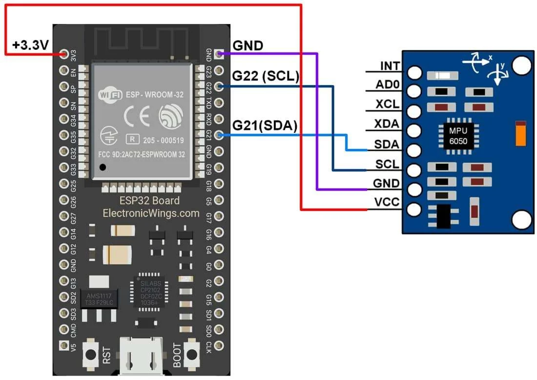
Credits: - https://i0.wp.com/randomnerdtutorials.com/wp-content/uploads/2021/01/MPU6050-ESP8266-NodeMCU-Wiring-Schematic-Diagram-Circuit.png?quality=100&strip=all&ssl=1

Let’s take an example from the Adafruit_MPU6050 library to understand how to setup events for sensor and print reading to serial monitor

// Basic demo for accelerometer readings from Adafruit MPU6050
#include <Adafruit_MPU6050.h>
#include <Adafruit_Sensor.h>
#include <Wire.h>
Adafruit_MPU6050 mpu;
void setup(void) {
Serial.begin(115200);
while (!Serial)
delay(10); // will pause Zero, Leonardo, etc until serial console opens
Serial.println("Adafruit MPU6050 test!");
// Try to initialize!
if (!mpu.begin()) {
Serial.println("Failed to find MPU6050 chip");
while (1) {
delay(10);
}
}
Serial.println("MPU6050 Found!");
mpu.setAccelerometerRange(MPU6050_RANGE_8_G);
Serial.print("Accelerometer range set to: ");
switch (mpu.getAccelerometerRange()) {
case MPU6050_RANGE_2_G:
Serial.println("+-2G");
break;
case MPU6050_RANGE_4_G:
Serial.println("+-4G");
break;
case MPU6050_RANGE_8_G:
Serial.println("+-8G");
break;
case MPU6050_RANGE_16_G:
Serial.println("+-16G");
break;
}
mpu.setGyroRange(MPU6050_RANGE_500_DEG);
Serial.print("Gyro range set to: ");
switch (mpu.getGyroRange()) {
case MPU6050_RANGE_250_DEG:
Serial.println("+- 250 deg/s");
break;
case MPU6050_RANGE_500_DEG:
Serial.println("+- 500 deg/s");
break;
case MPU6050_RANGE_1000_DEG:
Serial.println("+- 1000 deg/s");
break;
case MPU6050_RANGE_2000_DEG:
Serial.println("+- 2000 deg/s");
break;
}
mpu.setFilterBandwidth(MPU6050_BAND_21_HZ);
Serial.print("Filter bandwidth set to: ");
switch (mpu.getFilterBandwidth()) {
case MPU6050_BAND_260_HZ:
Serial.println("260 Hz");
break;
case MPU6050_BAND_184_HZ:
Serial.println("184 Hz");
break;
case MPU6050_BAND_94_HZ:
Serial.println("94 Hz");
break;
case MPU6050_BAND_44_HZ:
Serial.println("44 Hz");
break;
case MPU6050_BAND_21_HZ:
Serial.println("21 Hz");
break;
case MPU6050_BAND_10_HZ:
Serial.println("10 Hz");
break;
case MPU6050_BAND_5_HZ:
Serial.println("5 Hz");
break;
}
Serial.println("");
delay(100);
}
void loop() {
/* Get new sensor events with the readings */
sensors_event_t a, g, temp;
mpu.getEvent(&a, &g, &temp);
/* Print out the values */
Serial.print("Acceleration X: ");
Serial.print(a.acceleration.x);
Serial.print(", Y: ");
Serial.print(a.acceleration.y);
Serial.print(", Z: ");
Serial.print(a.acceleration.z);
Serial.println(" m/s^2");
Serial.print("Rotation X: ");
Serial.print(g.gyro.x);
Serial.print(", Y: ");
Serial.print(g.gyro.y);
Serial.print(", Z: ");
Serial.print(g.gyro.z);
Serial.println(" rad/s");
Serial.print("Temperature: ");
Serial.print(temp.temperature);
Serial.println(" degC");
Serial.println("");
delay(500);
}

CODE EXPLANATION

In this code we start with including necessary library i.e

#include <Adafruit_MPU6050.h>
#include <Adafruit_Sensor.h>
#include <Wire.h>

Now let’s create instance for mpu6050 sensor

Adafruit_MPU6050 mpu;

In setup we begin serial communication and check if it fail then to wait until it successfully begin.

Serial.begin(115200);
while (!Serial)
delay(10); // will pause Zero, Leonardo, etc until serial console opens

After that we print Adafruit MPU6050 test and then check if the sensor is connected/wired properly or not. If not, the code runs into infinite loop. If found print MPU6050 Found!

 Serial.println("Adafruit MPU6050 test!");
 // Try to initialize!
 if (!mpu.begin()) {
Serial.println("Failed to find MPU6050 chip");
while (1) {
delay(10);
  }
 }
 Serial.println("MPU6050 Found!");

The function mpu.AccelerometerRange(MPU6050 RANGE _8_G) and mpu.setGyroRange(MPU6050_RANGE_500_DEG) sets the range of acceleration and gyroscope that to be measure. Here acceleration is set to MPU6050 RANGE _8_G which means it can detect acceleration from -8g to +8g whereas MPU6050_RANGE_500_DEG sets the range from -500deg/s to +500deg/s. To know which range is currently set we use mpu.getAccelerometerRange() and mpu.getGyroRange() and print it.

mpu.setAccelerometerRange(MPU6050_RANGE_8_G);
Serial.print("Accelerometer range set to: ");
switch (mpu.getAccelerometerRange()) {
case MPU6050_RANGE_2_G:
Serial.println("+-2G");
break;
case MPU6050_RANGE_4_G:
Serial.println("+-4G");
break;
case MPU6050_RANGE_8_G:
Serial.println("+-8G");
break;
case MPU6050_RANGE_16_G:
Serial.println("+-16G");
break;
}
mpu.setGyroRange(MPU6050_RANGE_500_DEG);
Serial.print("Gyro range set to: ");
 switch (mpu.getGyroRange()) {
case MPU6050_RANGE_250_DEG:
Serial.println("+- 250 deg/s");
break;
case MPU6050_RANGE_500_DEG:
Serial.println("+- 500 deg/s");
break;
case MPU6050_RANGE_1000_DEG:
Serial.println("+- 1000 deg/s");
break;
case MPU6050_RANGE_2000_DEG:
Serial.println("+- 2000 deg/s");
break;
}

Senor is ready to read the values and to get the reading we create sensor event sensors_event_t a, g, temp; and store reading in them using mpu.getEvent(&a, &g, &temp). start printing stored values using a.acceleration.x/y/z for acceleration , g.gyro.x/y/z for gyroscope and temp.temperature respectively. Also adding delay of 500ms between consecutive reading.

void loop() {
 /* Get new sensor events with the readings */
 sensors_event_t a, g, temp;
 mpu.getEvent(&a, &g, &temp);
 /* Print out the values */
 Serial.print("Acceleration X: ");
 Serial.print(a.acceleration.x);
 Serial.print(", Y: ");
 Serial.print(a.acceleration.y);
 Serial.print(", Z: ");
 Serial.print(a.acceleration.z);
 Serial.println(" m/s^2");
 Serial.print("Rotation X: ");
 Serial.print(g.gyro.x);
 Serial.print(", Y: ");
 Serial.print(g.gyro.y);
 Serial.print(", Z: ");
 Serial.print(g.gyro.z);
 Serial.println(" rad/s");
 Serial.print("Temperature: ");
 Serial.print(temp.temperature);
 Serial.println(" degC");
 Serial.println("");
 delay(500);
}

EXAMPLE

CIRCUIT DIAGRAM REMAINS SAME.

This code will make decision when gyro values exceed certain limit. Here we are taking a scenario where mpu6050 is mounted on a glove and we want to know the orientation of hand. so let’s see the code.

#include <Adafruit_MPU6050.h>
#include <Adafruit_Sensor.h>
#include <Wire.h>
Adafruit_MPU6050 mpu;
float rawxaxis = 0;
float rawyaxis = 0;
float rawzaxis = 0;
float pitch = 0;
float roll = 0;
float yaw = 0;
String prevpitch="MID";
String prevroll="MID";
String prevyaw="MID";
float caligyrox = 0, caligyroy = 0, caligyroz = 0;
void setup(void) {
 Serial.begin(115200);
 if (!mpu.begin()) {
Serial.println("Failed to find MPU6050 chip");
 } else {
Serial.println("MPU6050 Found!");
 }
 //Calibration logic
 float tempgx;
 float tempgy;
 float tempgz;
 for (int i = 0; i < 2000; i++) {
sensors_event_t a, g, temp;
mpu.getEvent(&a, &g, &temp);
tempgx = g.gyro.x;
tempgy = g.gyro.y;
tempgz = g.gyro.z;
caligyrox += tempgx;
caligyroy += tempgy;
caligyroz += tempgz;
 }
 caligyrox /= 2000;
 caligyroy /= 2000;
 caligyroz /= 2000;
}
void loop() {
sensors_event_t a, g, temp;
mpu.getEvent(&a, &g, &temp);
rawxaxis = g.gyro.x - abs(caligyrox);
rawyaxis = g.gyro.y - abs(caligyroy);
rawzaxis = g.gyro.z - abs(caligyroz);
for (int i = 0; i < 20; i++) {
if (abs(rawxaxis) > caligyrox && abs(roll + rawxaxis) <= 1000) {
   roll = roll + rawxaxis;
 }
if (abs(rawyaxis) > caligyroy && abs(pitch + rawyaxis) <= 1000) {
   pitch = pitch + rawyaxis;
 }
if (abs(rawzaxis) > caligyroz && abs(yaw + rawzaxis) <= 1000) {
   yaw = yaw + rawzaxis;
 }
 }
 if (yaw <= -950) {
  prevyaw="finger pointing right";
 } else if (yaw > 950) {
  prevyaw="finger pointing left";
 } else if (abs(yaw) > 0 && abs(yaw) < 900) {
  prevyaw="MID";
 }
 if (pitch <= -950) {
  prevpitch="down1";
 } else if (pitch > 950) {
  prevpitch="UP";
 } else if (abs(pitch) > 0 && abs(pitch) < 900) {
  prevpitch="MID";
 }
 if (roll <= -950) {
  prevroll="rigth";
 } else if (roll > 950) {
  prevroll="left";
 } else if (abs(roll) > 0 && abs(roll) < 900) {
  prevroll="MID";
 }
 Serial.print("pitch = ");
 Serial.print(prevpitch);
 Serial.print("\t");
 Serial.print("roll = ");
 Serial.print(prevroll);
 Serial.print("\t");
 Serial.print("yaw = ");
 Serial.println(prevyaw);
 delay(10);
}

CODE EXPLANATION

Let’s see the main logic and rest is all same.

float rawxaxis = 0;
float rawyaxis = 0;
float rawzaxis = 0;
float pitch = 0;
float roll = 0;
float yaw = 0;
String prevpitch="MID";
String prevroll="MID";
String prevyaw="MID";
float caligyrox = 0, caligyroy = 0, caligyroz = 0;

Declaring the variables that to be used.

  1. raw_axis = values that come from g.axis._ function.
  2. caligyro_ = values after calibrating the sensor
  3. pitch = gyro value of y
  4. roll = gyro value x
  5. yaw = gyro value z
  6. prev___=decision taken after evaluating their respective values

FOLLOWING PART OF THE CODE IS JUST FOR EXTRA INFO

 //Calibration logic
 for (int i = 0; i < 2000; i++) {
sensors_event_t a, g, temp;
  mpu.getEvent(&a, &g, &temp);
  caligyrox += g.gyro.x;
  caligyroy += g.gyro.y;
  caligyroz += g.gyro.z;
  delay(1);
 }
 caligyrox /= 2000;
 caligyroy /= 2000;
 caligyroz /= 2000;

When the senor is kept on flat surface the ideally the reading should be zero but gives non-zero values. This is part of the code handles those values. Here we take gyro values of all 3 axis in the interval of 1ms and repeatedly add them and store them in caligyro_. After that we take mean for the values. These values can be used as error correction value i.e. we subtract current readings with their respective caligyro_ value so when current reading is equal to this value it makes it to zero indicating back to original position. 

Let’s see loop() code

 sensors_event_t a, g, temp;
 mpu.getEvent(&a, &g, &temp);
 rawxaxis = g.gyro.x - abs(caligyrox);
 rawyaxis = g.gyro.y - abs(caligyroy);
 rawzaxis = g.gyro.z - abs(caligyroz);

Taking current readings and correcting it by subtracting caligyro_ value.

 for (int i = 0; i < 20; i++) {
if (abs(rawxaxis) > caligyrox && abs(roll + rawxaxis) <= 1000) {
   roll = roll + rawxaxis;
  }
if (abs(rawyaxis) > caligyroy && abs(pitch + rawyaxis) <= 1000) {
   pitch = pitch + rawyaxis;
  }
if (abs(rawzaxis) > caligyroz && abs(yaw + rawzaxis) <= 1000) {
   yaw = yaw + rawzaxis;
  }
 }

To increase the accuracy of the decision we make decision based on the 20 readings and not one. We use caligyro_ value as a threshold (i.e. only considering reading that are greater than caligyro_ to negelect change due to small vibration of hand) and make sure that the reading does not exceed 1000. The reason for setting limit is that when orientation of hand changes the readings spikes up but when the orientation is maintained the values decreases gradually. To solve this, we add current reading to previous reading so that the spike is maintained.

  if (yaw <= -950) {
  prevyaw="finger pointing right";
 } else if (yaw > 950) {
  prevyaw="finger pointing left";
 } else if (abs(yaw) > 0 && abs(yaw) < 900) {
  prevyaw="MID";
 }
 if (pitch <= -950) {
  prevpitch="down1";
 } else if (pitch > 950) {
  prevpitch="UP";
 } else if (abs(pitch) > 0 && abs(pitch) < 900) {
  prevpitch="MID";
 }
 if (roll <= -950) {
  prevroll="rigth";
 } else if (roll > 950) {
  prevroll="left";
 } else if (abs(roll) > 0 && abs(roll) < 900) {
  prevroll="MID";
 }

Making decision. Setting threshold for each axis to tell the orientation of hand.You can check rotating in which direction about the axis will give + or - value . The reason for setting threshold is that rotating at high speed about axis add or subtract previous pitch/roll/yaw value by small value. This leads to giving out + or - even when the orientation is back to original. Therefore, we do not make decision based on sign of value.