MKR1000 - Arduino IoT Cloud - IFTT Phone Call
by rems7581 in Circuits > Arduino
3770 Views, 25 Favorites, 0 Comments
MKR1000 - Arduino IoT Cloud - IFTT Phone Call

Arduino IoT Cloud is a great platform! Associated with connected boards like the MKR1000, it is now possible to create a connected object very easily, and to use the "Dashboard" integrated into the platform to interact via the Internet.
All this is done for free, the code and the implementation are very simple, because the "Networking" layer is assisted in a very intuitive way. Reading the evolution curve of an analog sensor remotely, or command the switching of a relay with your phone takes only a few minutes of installation and code, without any real difficulty.
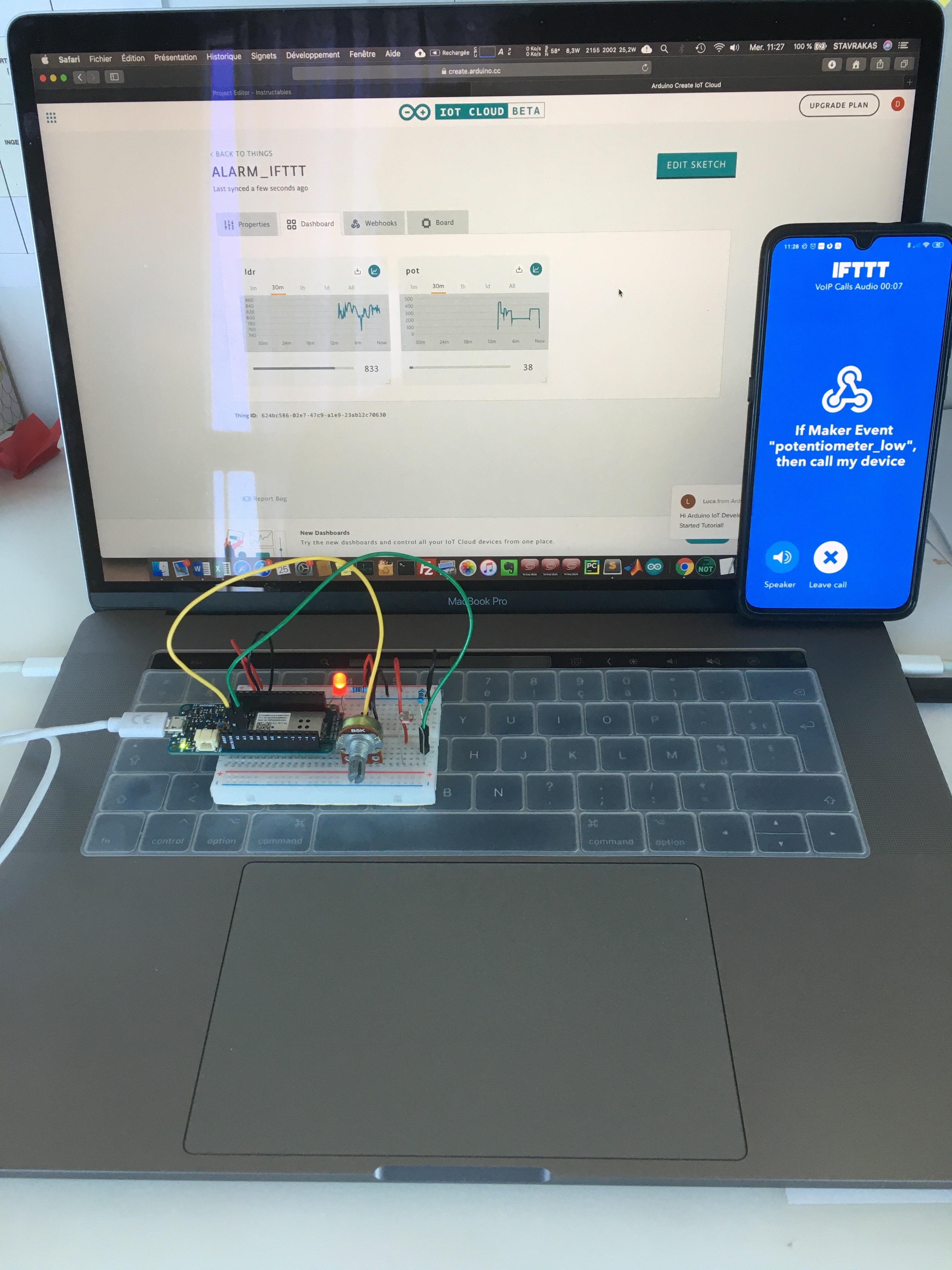
For this project, we want to display the data of 2 sensors on the Arduino IoT Cloud dashboard, and trigger an alert on a phone if the value of sensor 1 is below a threshold.
Supplies
Note : Amazon supplier is indicative ...
1. Arduino MKR1000 x 1
2. Potentiometer x 1
3. LDR x 1
4. Red LED 5mm x 1
5. 220Ω Resistor x 1
6. 10kΩ Resistor x 1
7. Breadboard x 1
8. Jumpers x 1
Arduino IoT Cloud and Webhooks: the Problem...


Arduino IoT Cloud offers a "Webhooks" service that allows you to send sensor data to third-party applications (Google Spreadsheets, IFTTT, Zapier, etc.).
In the absence of any setting, it seems that the Webhook is triggered each time a data is sent to the Arduino Cloud. Unless there is third-party service processing, if there is more than one sensor to monitor, the alert will be triggered each time the data changes. This is not what we want for this project.
The purpose of this tutorial is therefore to trigger the alert and send it to the webhook from the Arduino code, without going through the webhooks service of the platform, whose apparent limitations we mentioned earlier. We also keep the ease of displaying data on the Arduino IoT Cloud dashboard.
Wiring

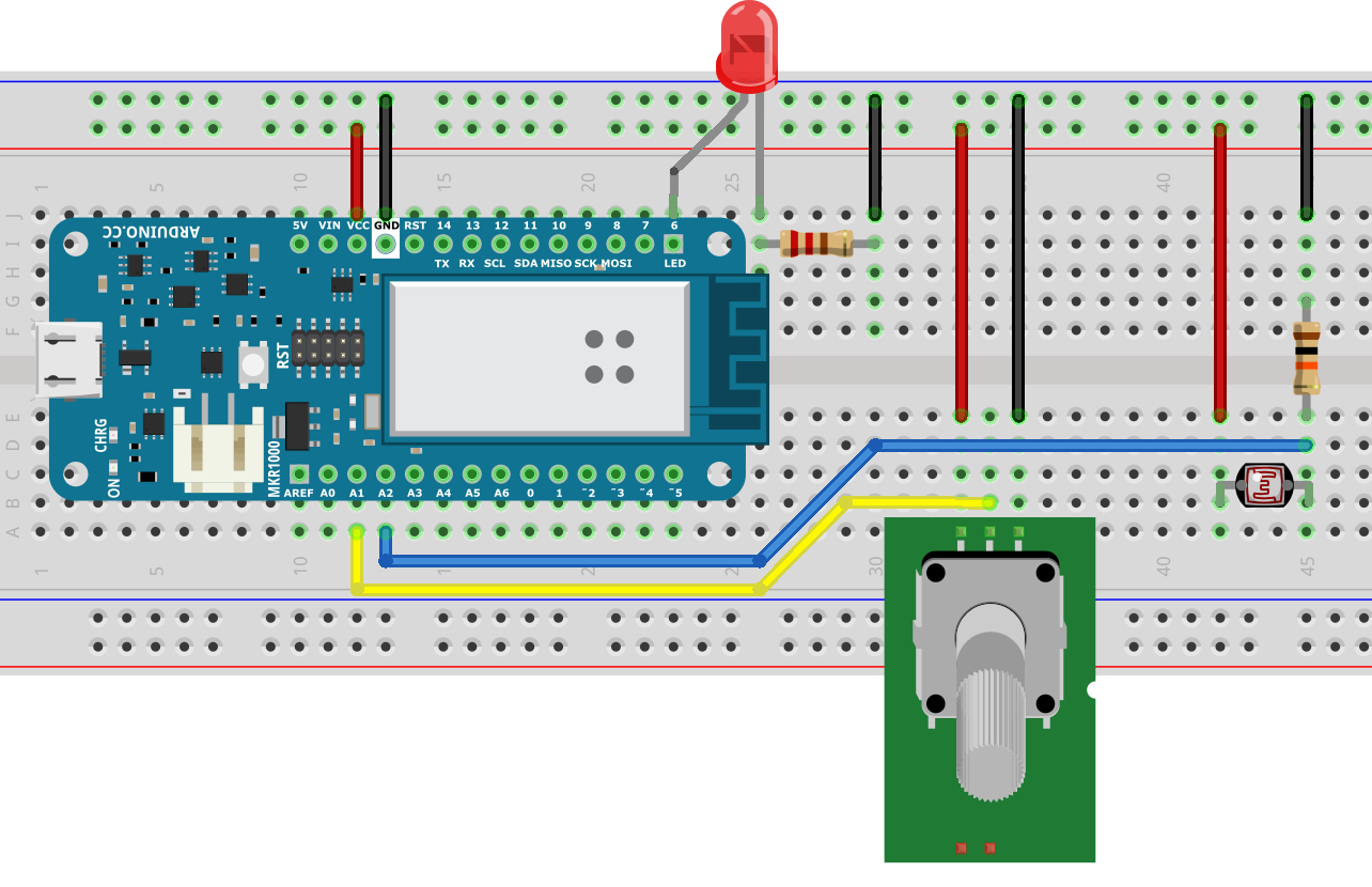
The wiring for this project is very simple, just keep in mind that the MKR1000 does not support voltages higher than 3.3V on the I/O. This is why the power supply line of the breadboard is connected to the VCC pin of the MKR1000.
Connection to Arduino Iot Cloud

Go to https://create.arduino.cc/iot/things and create a new account.
Click on the 9 points at the top left and choose "Arduino IoT Cloud".
Board Setup...


ATTENTION! Do not yet connect the card to the USB port of your computer!
1. Add a new "Thing". This represents a connected object associated with a board.
2. Choose the “MKR1000” board.
3. Follow the procedure (you will need to install the “Arduino Create Plugin” software in particular).
4. Connect the MKR1000 to the computer.
5. Give a name to the board.
6. Follow the procedure (this step allows you to configure the card's security chip).
7. Return to the main screen of the Cloud interface.
Creation of a Connected Object ("Thing")

Give a name to the new object ("Thing") that we are going to create for this project, and choose the board that we just installed.
Add a New Property


Note: each function of the project (sensor, actuator, etc.) must be associated with an single property.
1. Add a New Property. In our case, it is one of the 2 sensors of the project.
2. Configure the property as shown in picture #2 (this is the property associated with the potentiometer).
Note: Permissions are particularly important:
• Read & Write: it is possible to control an object from the cloud
• Read Only: only data is displayed in the cloud. In our case, we simply want to display the value of a sensor, so we will choose "Read Only".
3. Perform the 2 previous sub-steps to create a property associated with the LDR, then click on “Edit Sketch” to start coding.
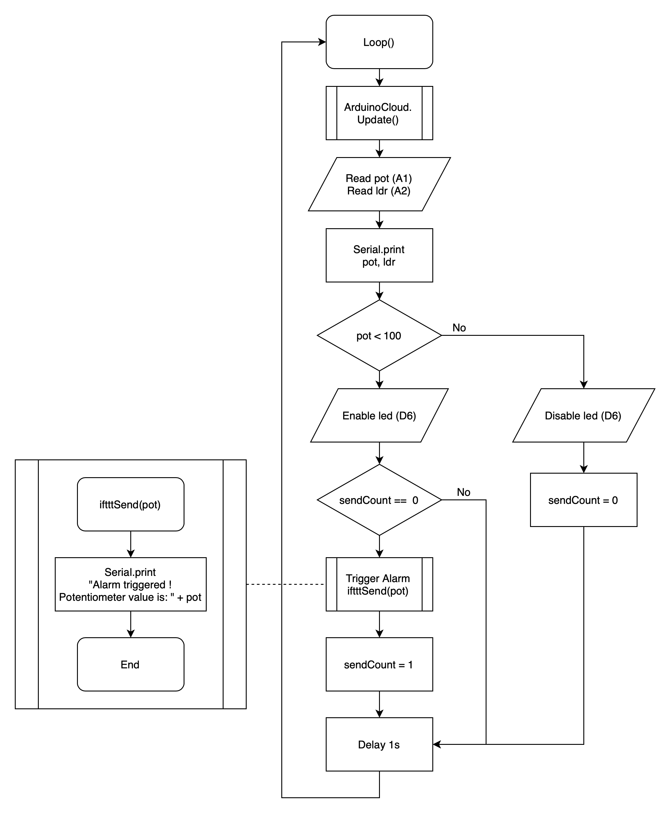
Code Overview (Algorigram)

First, we will create the code for:
• Read the analog values of the sensors
• Send data to the Cloud
• Trigger an alert when the potentiometer value is too low (for the moment send a message to the serial monitor + switch on a LED). We will deal with IFTTT later in this tutorial
Coding on the "WEB EDITOR"


1. In the web editor, copy / paste the provided code (replace the default code).
Note: the default code includes most of the commands and functions specific to using the cloud. The copied code enriched it with elements specific to the project.
/* <br>  The following variables are automatically generated and updated when changes are made to the Thing properties
  int ldr;
  int pot;
  Properties which are marked as READ/WRITE in the Cloud Thing will also have functions
  which are called when their values are changed from the Dashboard.
  These functions are generated with the Thing and added at the end of this sketch.
*/
int sendCount = 0;
#define potPin 1
#define ldrPin 2
#define ledPin 6
#include "thingProperties.h"
void setup() {
  Serial.begin(9600);
  delay(1500);
  pinMode(6, OUTPUT);
  // Defined in thingProperties.h
  initProperties();
  // Connect to Arduino IoT Cloud
  ArduinoCloud.begin(ArduinoIoTPreferredConnection);
  /*
     The following function allows you to obtain more information
     related to the state of network and IoT Cloud connection and errors
     the higher number the more granular information you’ll get.
     The default is 0 (only errors).
     Maximum is 4
 */
  setDebugMessageLevel(2);
  ArduinoCloud.printDebugInfo();
}
void loop() {
  ArduinoCloud.update();
  pot = analogRead(1);
  ldr = analogRead(2);
  Serial.println("pot = " + String(pot) + " ldr = " + String(ldr));
  if (pot < 100) {
    digitalWrite(ledPin, HIGH);
    if (sendCount == 0) {
      iftttSend(pot);
      sendCount = 1;
    }
  }
  else {
    digitalWrite(ledPin, LOW);
    sendCount = 0;
  }
  delay(1000);
}
void iftttSend(int val) {
  String str_val = String(val);
  Serial.println("Alarm triggered ! Potentiometer value is: " + str_val);
}
2. Go to the "Secret" tab and complete the connection information for your WIFI connection point.
Downloads
Upload Code to the Board and View Data on the Cloud Dashboard


1. Click on the "UPLOAD" button, then wait for the program to be compiled and uploaded to the board.
2. Once the program has been uploaded (green strip), click on "Monitor" to access the messages sent on the serial port.
3. Manipulate the potentiometer, below 100, a message should indicate that the alarm has been triggered.
4. Click "GO TO IOT CLOUD" to access the data sent online.
5. Go to the "Dashboard" tab, watch the values evolve ... Success!
6. To carry out the alarm on the phone, return to the sketch editor.
Connection to IFTTT and Creation of an Applet


IFTTT (if this then that) is a free web service allowing its users to create simple instruction strings called applets. An applet is triggered by changes that occur within services. Wikipedia
1. Go to https://ifttt.com and create an account.
2. Then click on "Explore".
3. To create a new "Applet", click on "+".
Creation of a Trigger Event (Webhooks)


1. Click on "+ This" to create a new trigger event.
2. Enter "Webhooks" in the search engine, and click on the "Webhooks" icon.
Note: a webhook is a user-defined HTTP callback function, which retrieves and stores data from an event, generally external to your application. Wikipedia
3. Continue by clicking on the "Receive a web request" icon.
4. Enter the name of the event that will give trigger to the alert: "potentiometer_low", then click on "Create trigger".
Create an Action Associated With the Event Defined Above


1. Click on "+ That" to create an action associated with the event.
2. Enter "voip" in the search engine, and click on the "VoIP Calls" icon.
Note: Voice over Internet Protocol (VoIP), also called IP telephony, is a method and group of technologies for the delivery of voice communications and multimedia sessions over Internet Protocol (IP) networks, such as the Internet. Wikipedia
3. Click on "Call my device".
4. If necessary, modify the text of the message to be sent, then add the sentence "The potentiometer value is".
Then click on "Add ingredient" and select "Value1".
5. If all goes well, the text should take the variables "EventName" and "Value1" in gray. Then click on "Create action".
Note: “Value1”, “Value2”,… correspond to the values transmitted by the Webkook. These are JSON objects, we will use "Value1" to transmit the value of the potentiometer.
IFTTT Phone App

At this point, download the IFTTT smartphone app (Google Play or Apple Store). Install it and connect to your IFTTT account.
Webhooks URL and Testing the Alarm


1. Return to the IFTTT home page by clicking on the icon at the top left, then click on "Webhooks".
Note: We can observe that the Webhook created previously is present.
2. Click on "Documentation".
3. This page contains the URL of the HTTP request used to trigger the alert. To test it, copy it to an Internet browser, then:
• Replace “{event}” with “potentiometer_low”
• Add at the end "?Value1=255"
Exemple: https://maker.ifttt.com/trigger/potentiometer_low/with/key/<YOUR-KEY>?value1=255
If all goes well, you should receive a call on your phone…
4. Copy the key to a text file for use in the Arduino code.
Import the Modified "WIFI101" Library Into the Web Editor


We must now make the HTTP request from the MKR1000 card.
The libraries imported in the previous code use the library installed by default "WIFI101", which allows in particular to send HTTP requests.
But unfortunately, something is wrong between WiFi101 and IFTTT. This library must be modified.
1. Check that Arduino IDE software is installed on your computer.
2. Find in the file explorer the folder "WIFI101": Mac & PC: Documents / Arduino / libraries
3. Copy this folder to the desktop, and open the "WiFi.cpp" file with a text editor.
4. Replace line 317 with:
m2m_ssl_set_active_ciphersuites(SSL_CIPHER_RSA_WITH_AES_128_CBC_SHA | SSL_CIPHER_RSA_WITH_AES_128_CBC_SHA256 | SSL_CIPHER_RSA_WITH_AES_128_GCM_SHA256 | SSL_CIPHER_RSA_WITH_AES_256_CBC_SHA | SSL_CIPHER_RSA_WITH_AES_256_CBC_SHA256);
5. Then save the file "WiFi.cpp"
6. Compress the WIFI101 folder to create a WIFI101.zip file.
7. Return to the web editor, click on "Libraries" then tab "Custom" and import "WIFI101.zip" previously created.
Final Code and Alarm Test on the Phone


1. In the web editor, copy / paste the provided code (replace the previous code). Download the code on the card.
/*
  The following variables are automatically generated and updated when changes are made to the Thing properties
  int ldr;
  int pot;
  Properties which are marked as READ/WRITE in the Cloud Thing will also have functions
  which are called when their values are changed from the Dashboard.
  These functions are generated with the Thing and added at the end of this sketch.
*/
int sendCount = 0;
#define potPin 1
#define ldrPin 2
#define ledPin 6
#include "thingProperties.h"
WiFiSSLClient client;
char server[] = "maker.ifttt.com";
void setup() {
  Serial.begin(9600);
  delay(1500);
  pinMode(6, OUTPUT);
  // Defined in thingProperties.h
  initProperties();
  // Connect to Arduino IoT Cloud
  ArduinoCloud.begin(ArduinoIoTPreferredConnection);
  /*
     The following function allows you to obtain more information
     related to the state of network and IoT Cloud connection and errors
     the higher number the more granular information you’ll get.
     The default is 0 (only errors).
     Maximum is 4
 */
  setDebugMessageLevel(2);
  ArduinoCloud.printDebugInfo();
}
void loop() {
  ArduinoCloud.update();
  pot = analogRead(1);
  ldr = analogRead(2);
  Serial.println("pot = " + String(pot) + " ldr = " + String(ldr));
  if (pot < 100) {
    digitalWrite(ledPin, HIGH);
    if (sendCount == 0) {
      iftttSend(pot);
      sendCount = 1;
    }
  }
  else {
    digitalWrite(ledPin, LOW);
    sendCount = 0;
  }
  delay(1000);
}
void iftttSend(int val) {
  String str_val = String(val);
  Serial.println("Alarm triggered ! Potentiometer value is: " + str_val);
  String data = "{\"value1\":\"" + str_val + "\"}";
  // Connexion au serveur IFTTT
  Serial.println("Starting connection to server...");
  if (client.connectSSL(server, 443)) {
    Serial.println("Connected to server IFTTT, ready to trigger alarm...");
    // Make a HTTP request:
    client.println("POST /trigger/potentiometer_low/with/key/ HTTP/1.1"); // Replace "" by your own IFTTT key
    client.println("Host: maker.ifttt.com");
    client.println("Content-Type: application/json");
    client.print("Content-Length: ");
    client.println(data.length());
    client.println();
    client.print(data);
    Serial.println("IFTTT alarm triggered !");
  }
  else {
    Serial.println("Connection at IFTTT failed");
  }
}
2. Edit line 90 with your own IFTTT key.
3. Once the program has been sent (green strip), click on "Monitor" to access the messages sent on the serial port. Activate the potentiometer, below 100, a message should indicate that the alarm has been triggered ... and that the alert is gone on IFTTT ... you should receive a call on the phone !!
How about that?