MIDI Controller
.gif)
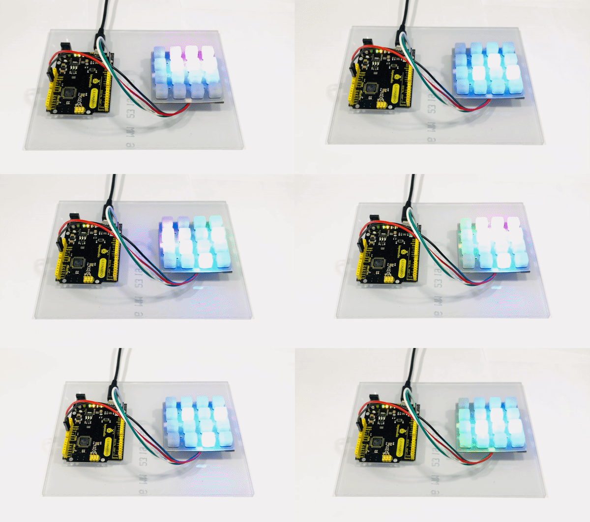
A MIDI (Musical Instrument Digital Interface) controller is a device that interacts with the MIDI interface and sends out musical commands to digital instruments such as a computer or a synthesizer. This project will give you a brief introduction on how MIDI works and how to set it up by building your own MIDI controller.
Supplies
Wiring the Controller
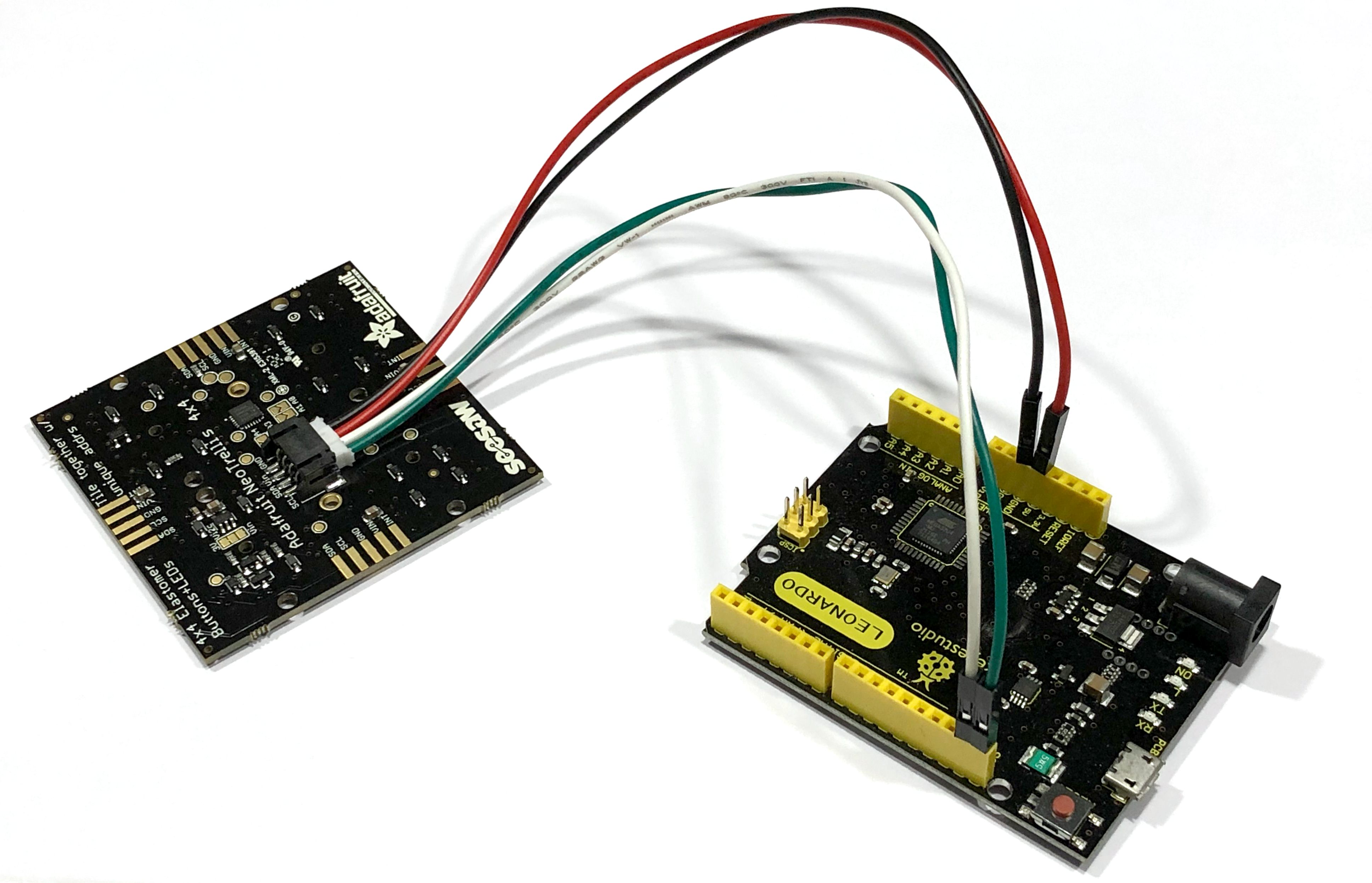
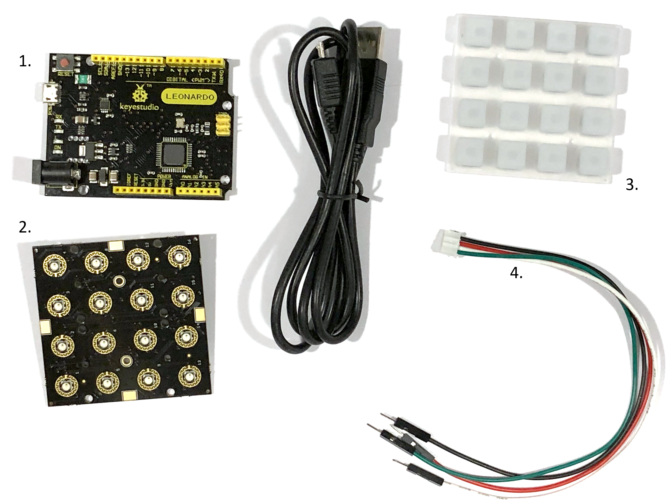
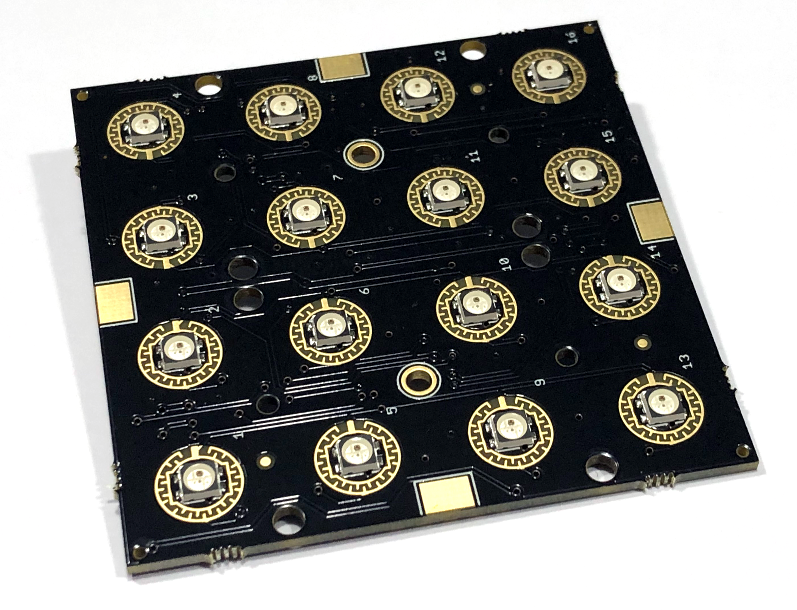
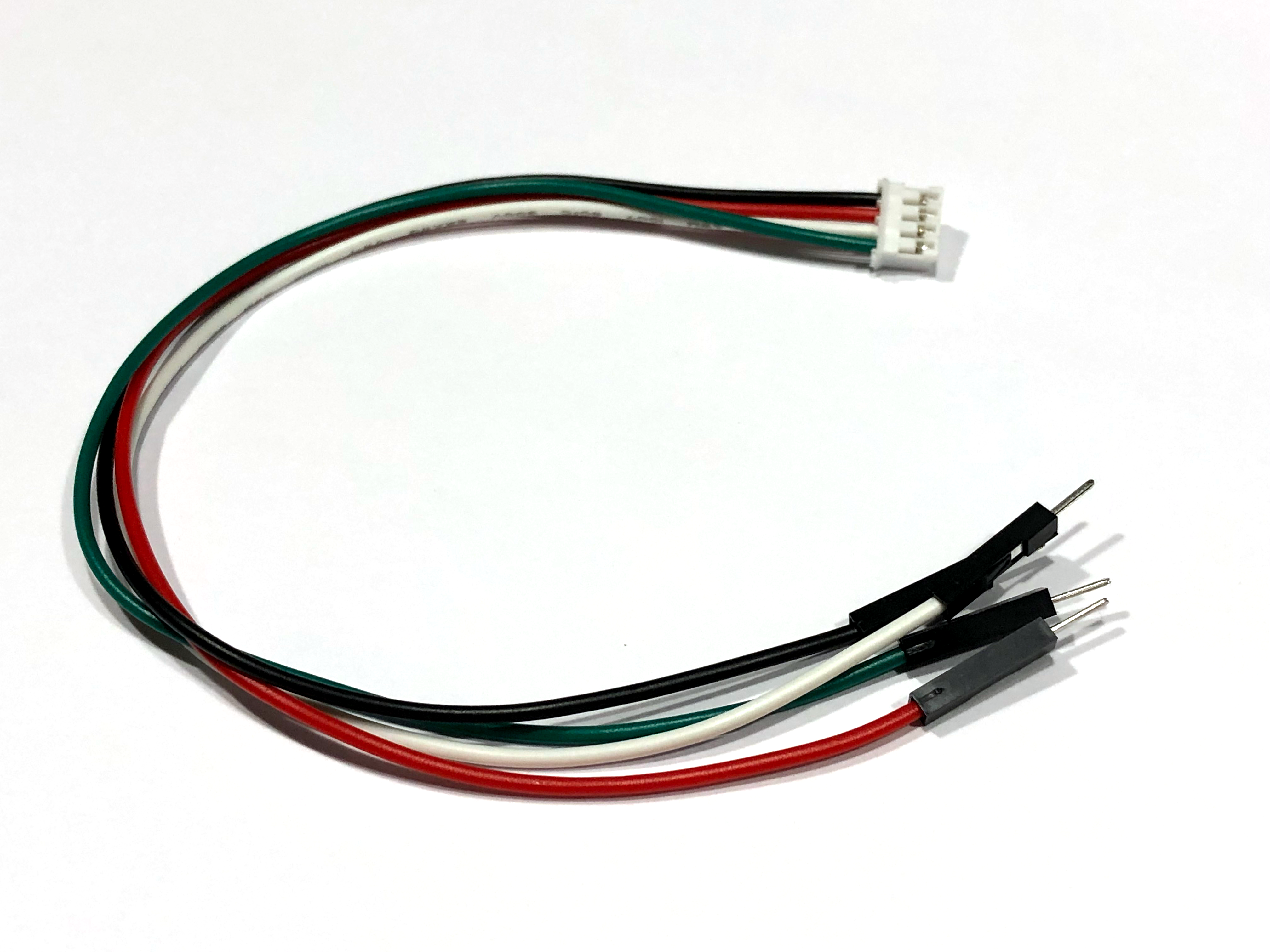
First you need to connect the JST cable to the Adafruit circuit board using the connector on the back. It goes in only in one direction, if it doesn't seem to fit, try flipping it.
The cable has 4 wires:
- Green
- White
- Red
- Black
The green and the white wires are data wires used to communicate with the Arduino Leonardo and the Adafruit circuit board. The red and black wires are power wires to power the Adafruit board.
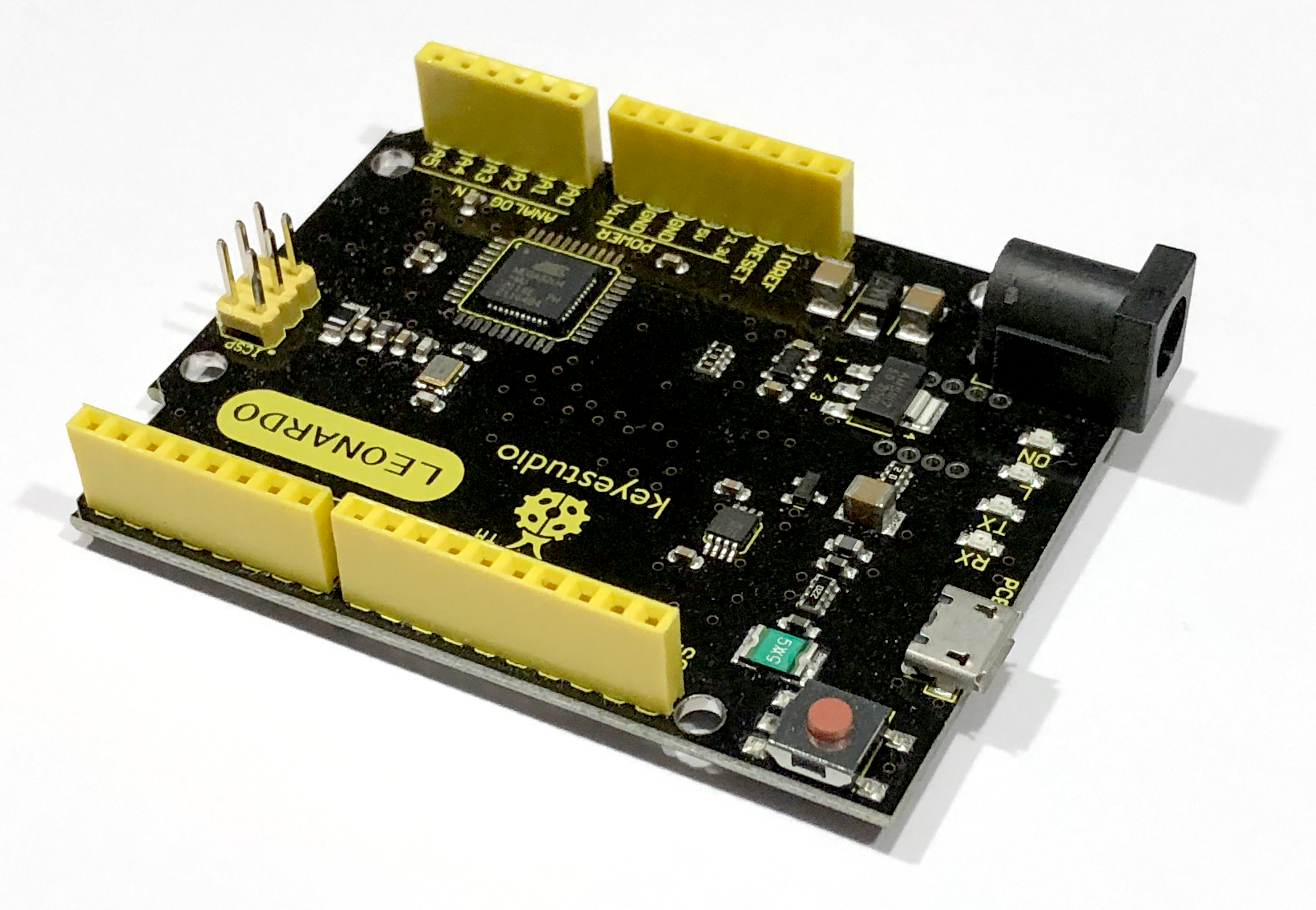
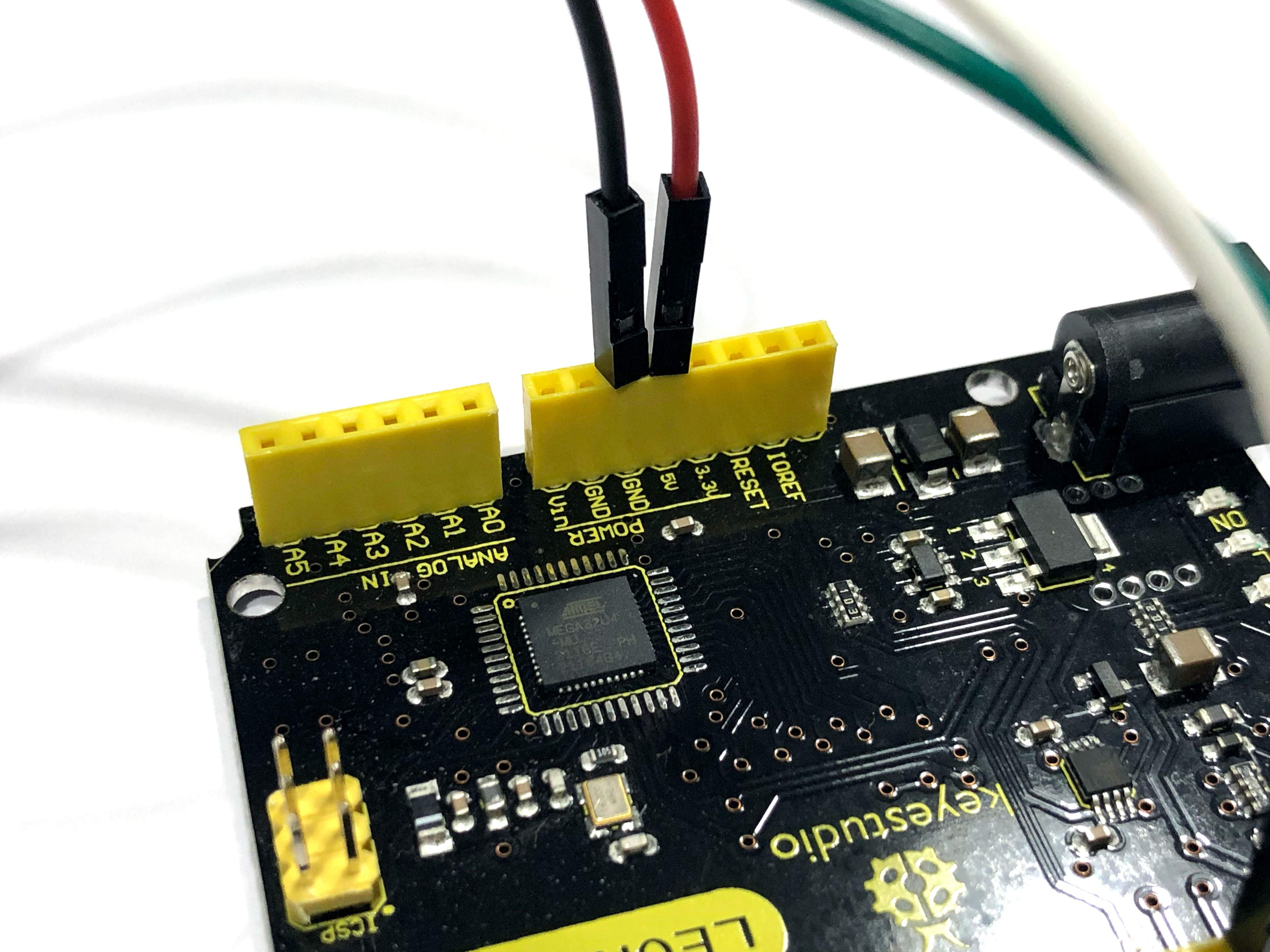
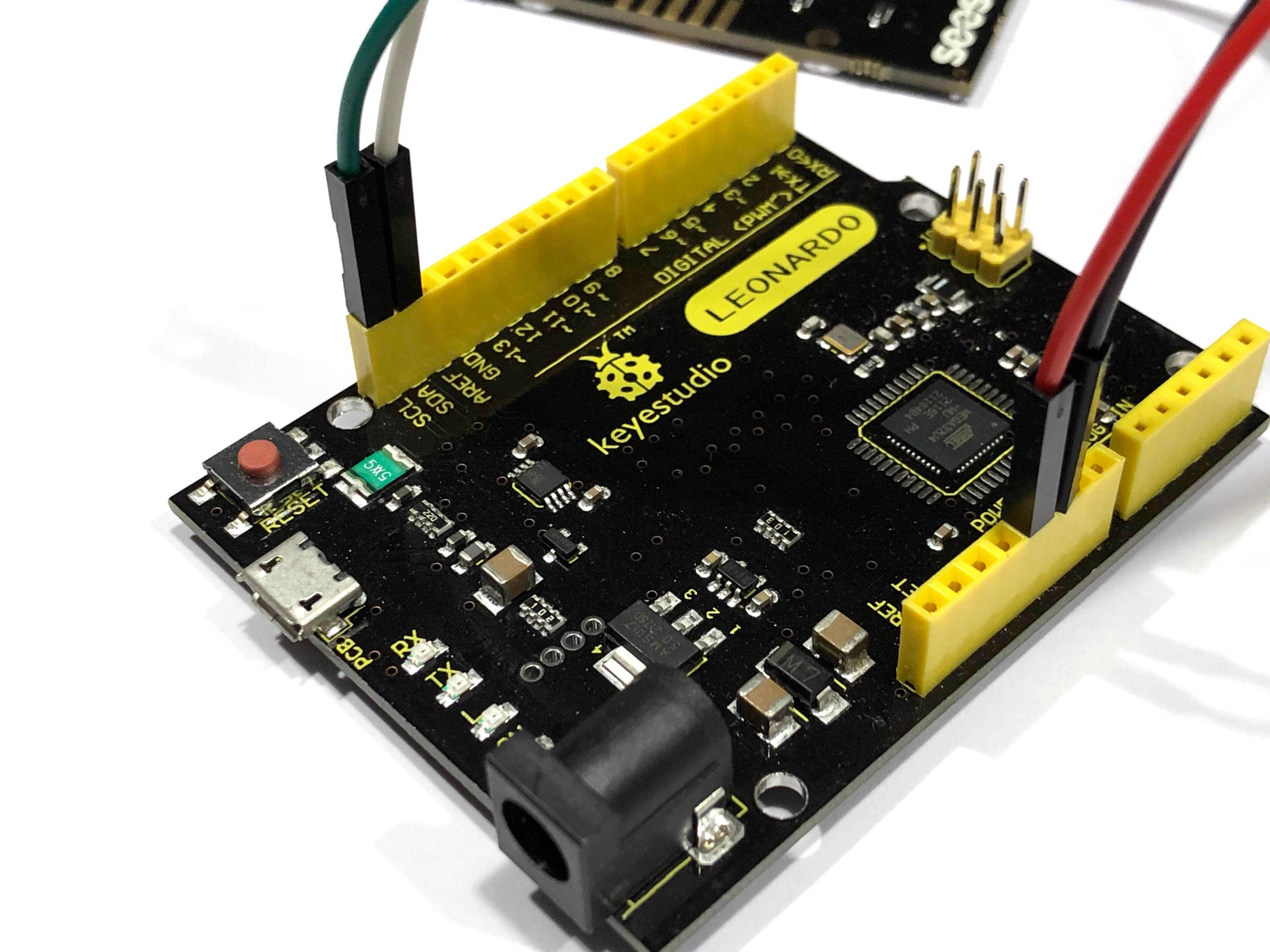
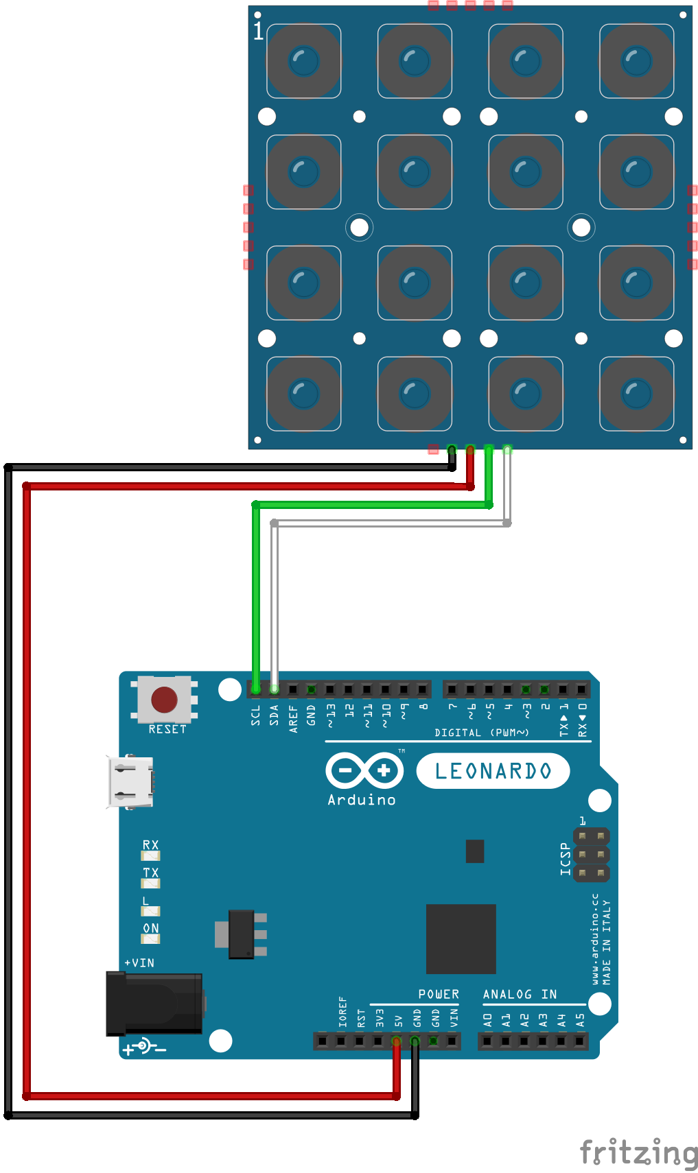
On the Arduino Leonardo board, locate the SDA and SCL ports, refer to the images if you are having trouble finding them. The green wire goes to the SCL port and the white wire goes to the SDA port.
Next, locate the 5V and GND ports. Connect the red wire to the 5V port and the black wire to the GND port.
Here is a quick wiring diagram:
- Green --> SCL
- White --> SDA
- Red --> 5V
- Black --> GND
Mounting the Electronics
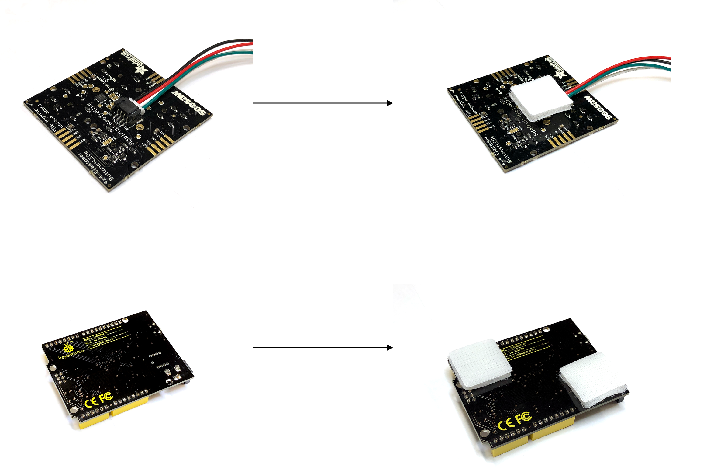
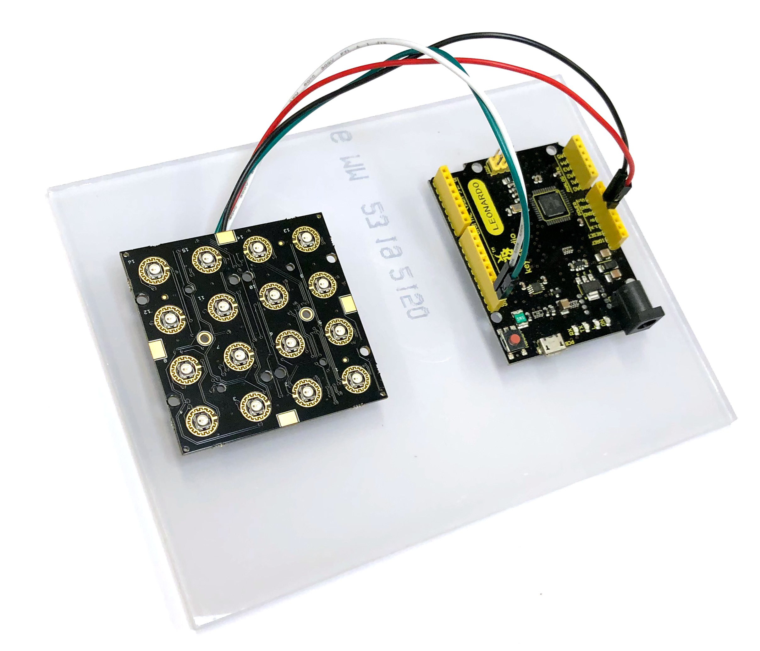
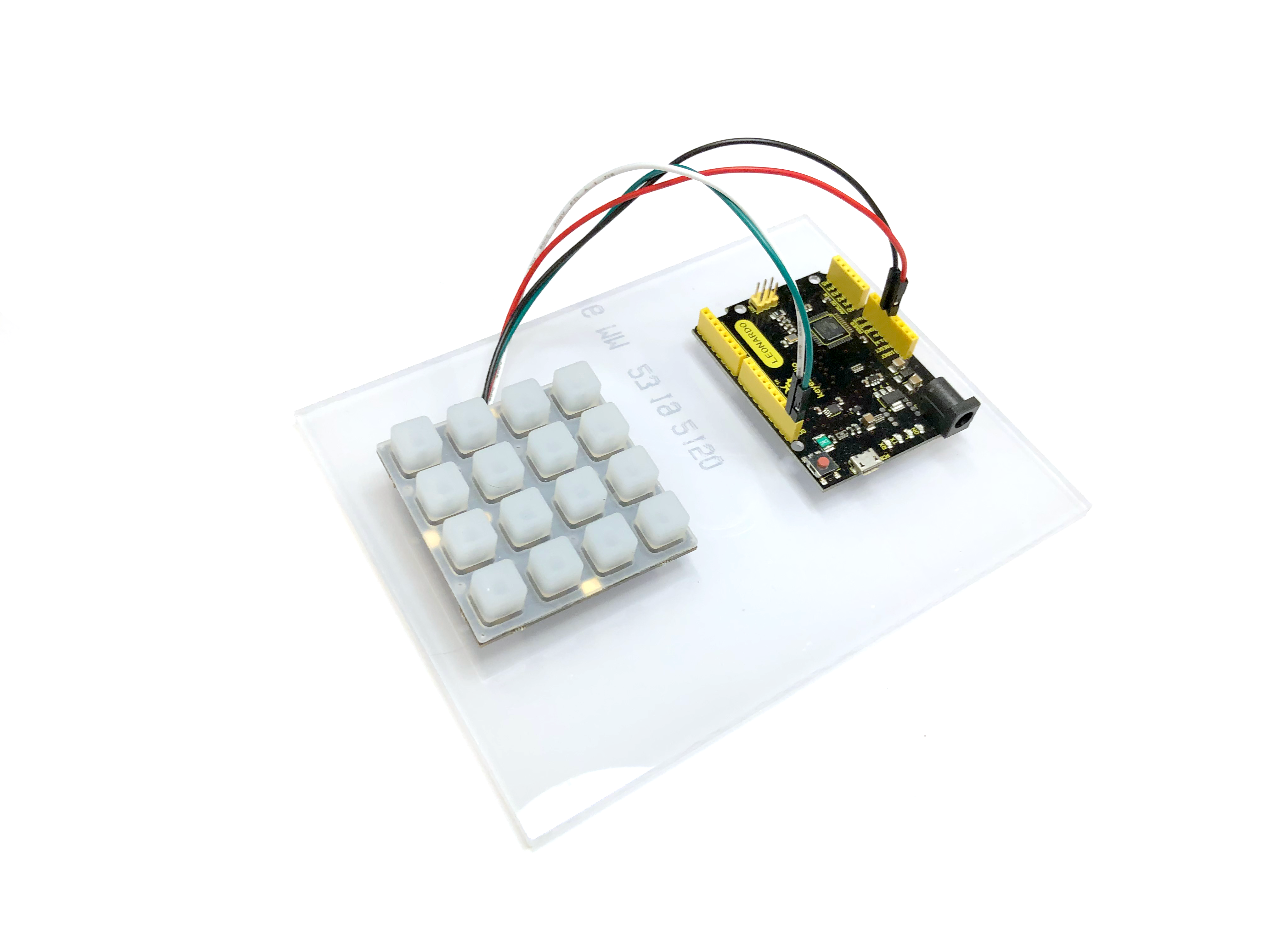
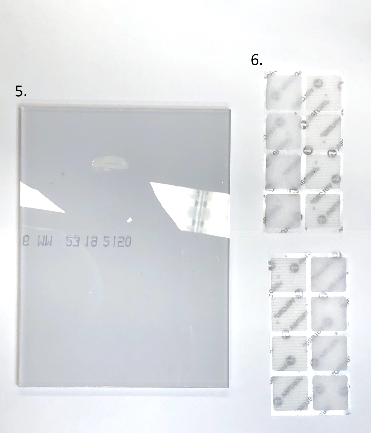
First, place two Velco squares on the back of the Arduino Leonardo board. Then place one Velcro square on the back of the Adafruit board (make sure it is placed on the JST connector because of the height difference).
After that, place the two circuit boards onto the polycarbonate sheet just like in the photo.
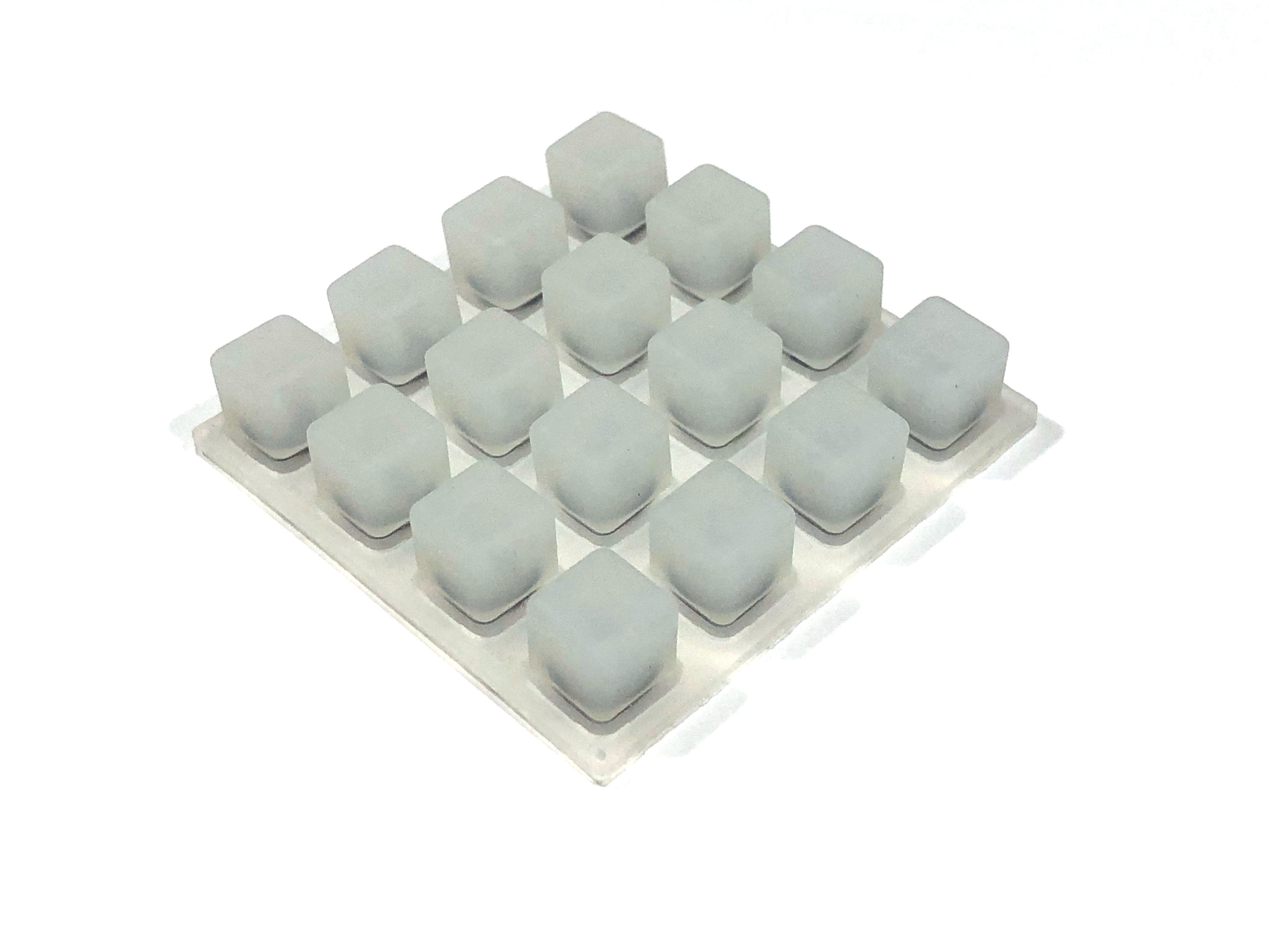
Lastly, place the Silicone keypad on top of the Adafruit Seesaw board.
Setting Up Programming Environment
Now you are almost ready to code!
The first step is to set up the programming environment. To do this, you must first install the IDE. This project will use the Visual Studio Code IDE.
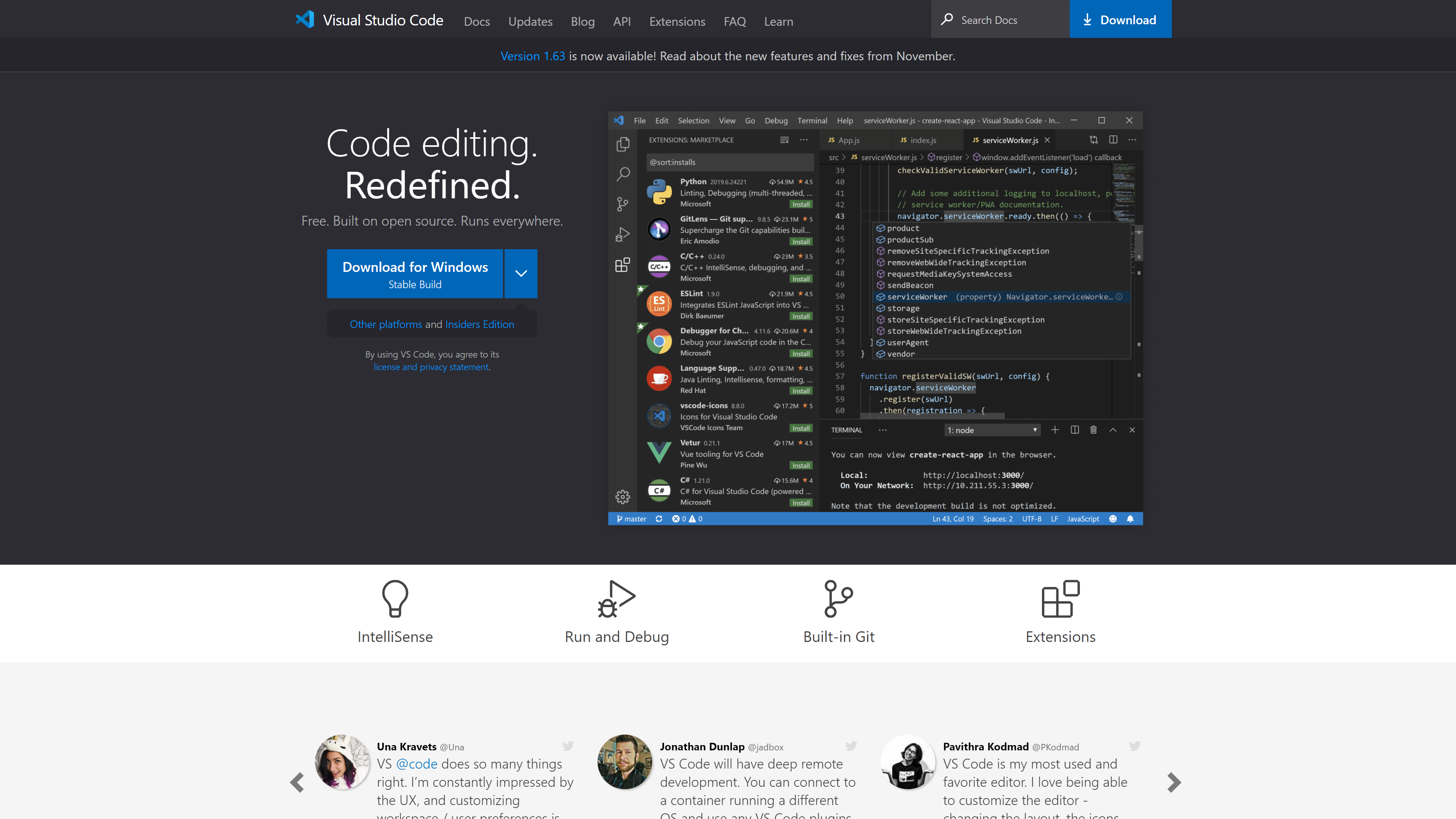
To install VS Code, first head over to their page at https://code.visualstudio.com and click on Download for Windows (Mac users will have a button called "Download Mac Universal").
After downloading it, follow the installation instructions to install the software onto your computer (default options works for this project).
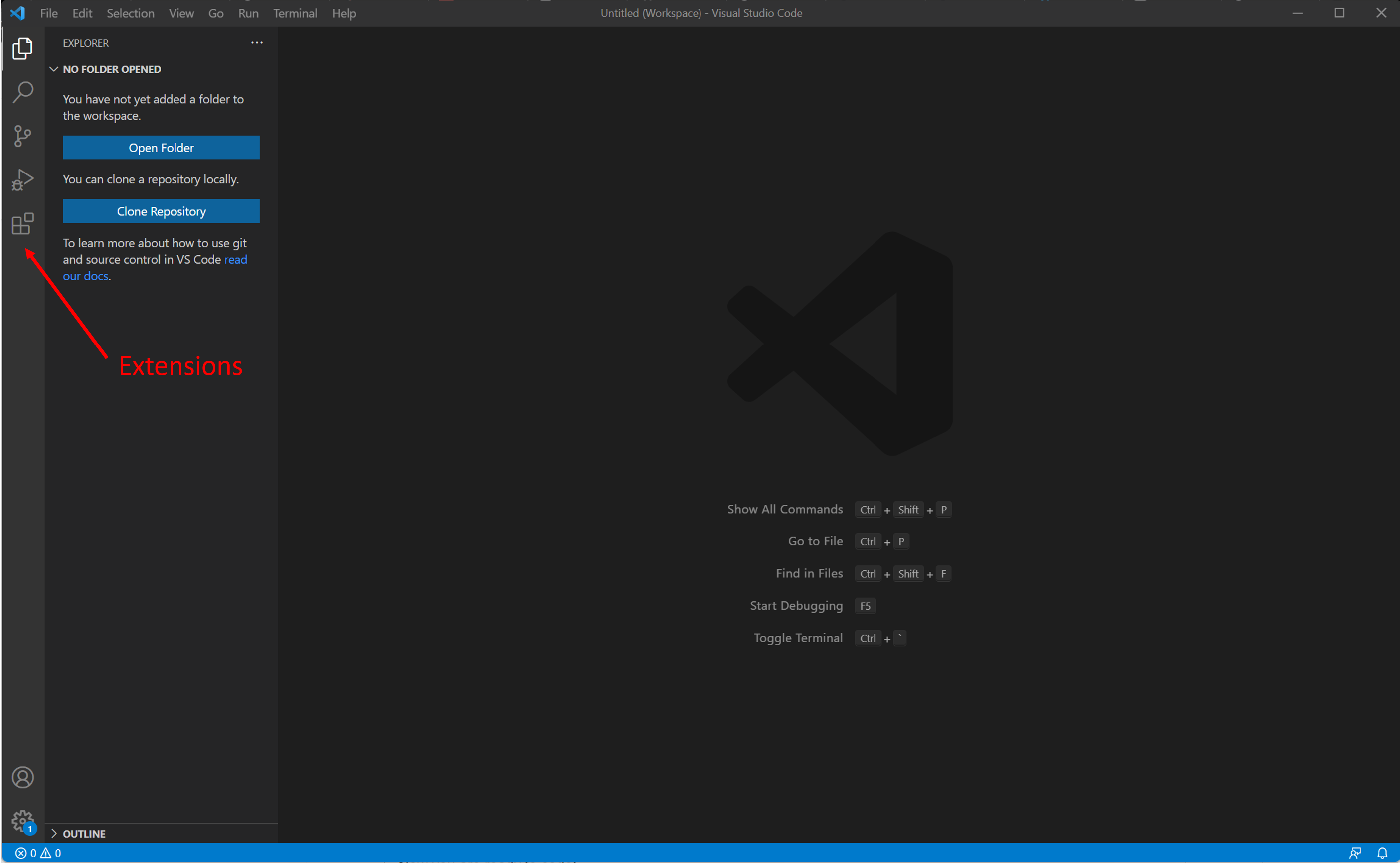
Once you have the software installed, open it and head over to Extensions
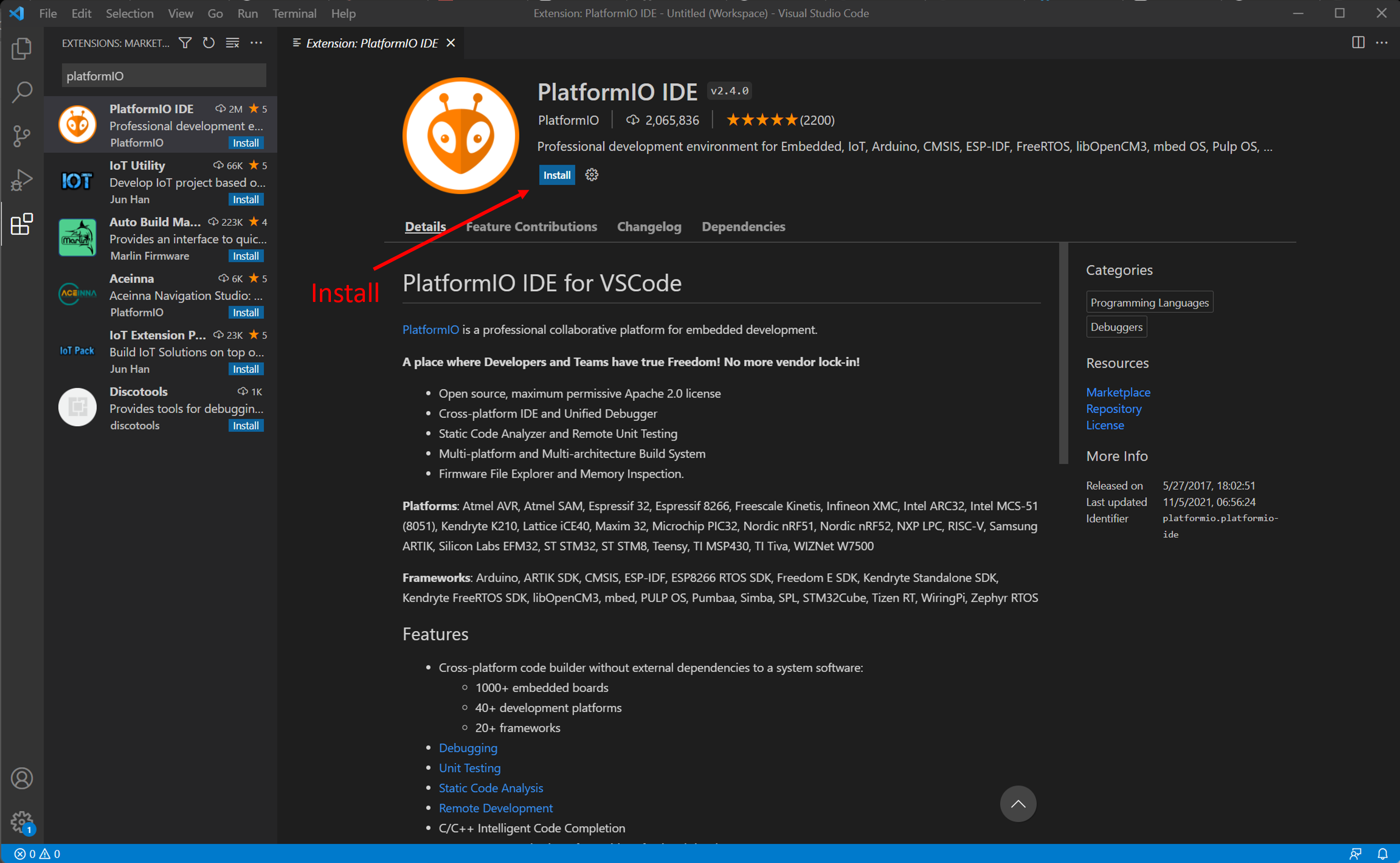
Then search search for PlatformIO and install it.
This will take a couple of minutes to install all the standard libraries.
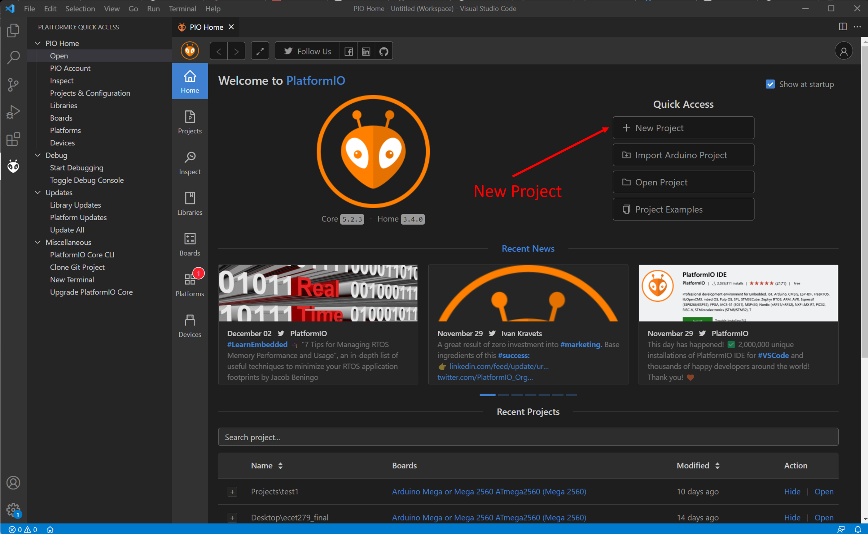
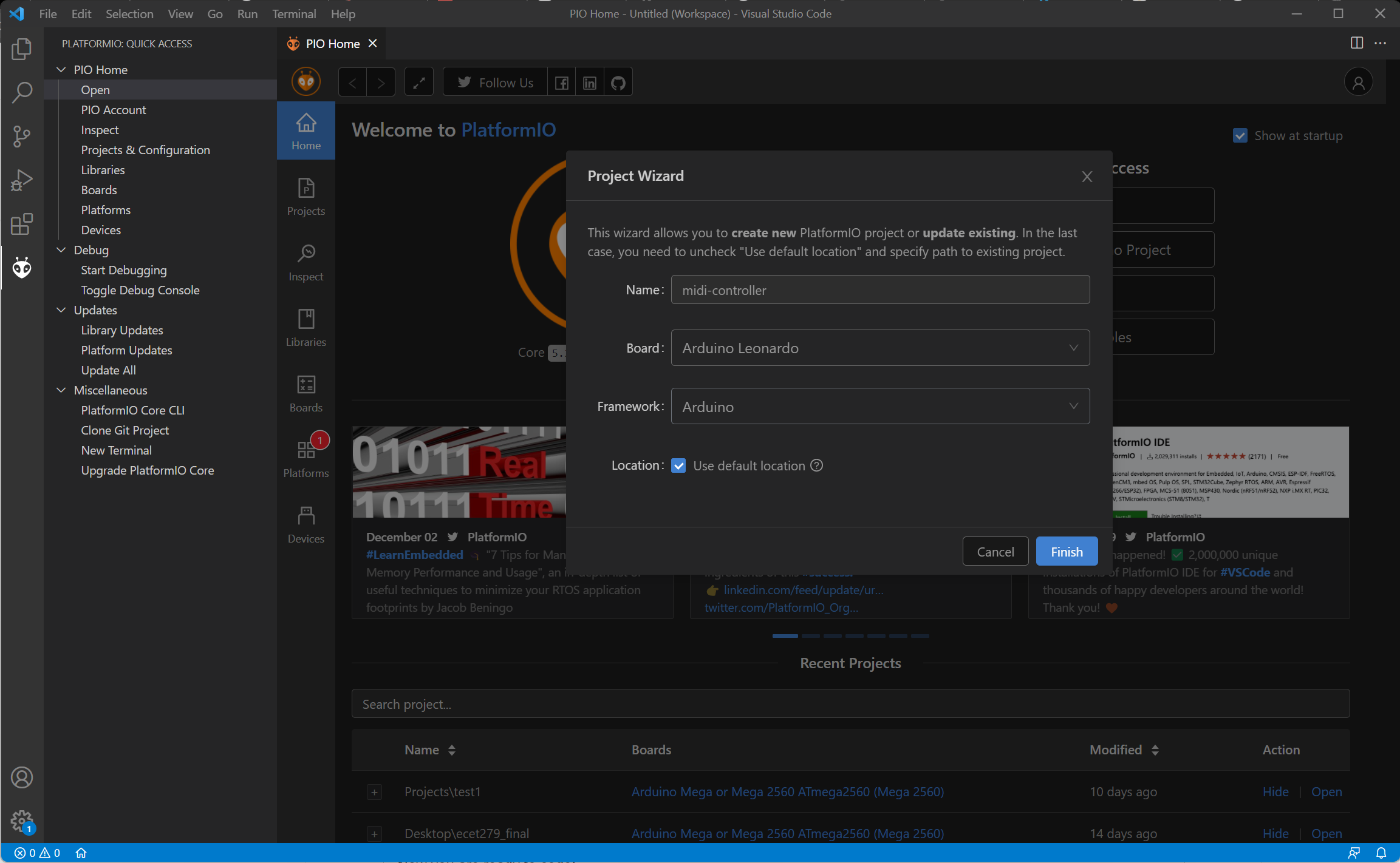
After the extension has successfully installed, you can start coding now, first, start out by creating a new project on PlatformIO. Next, give a name for your project, in this case I will use the name "midi-controller". Then select the "Arduino Leonardo" board from the boards list. Leave the other options to default.
Then click finish. This will take a few minutes as it is setting up a new project for you.
Programming
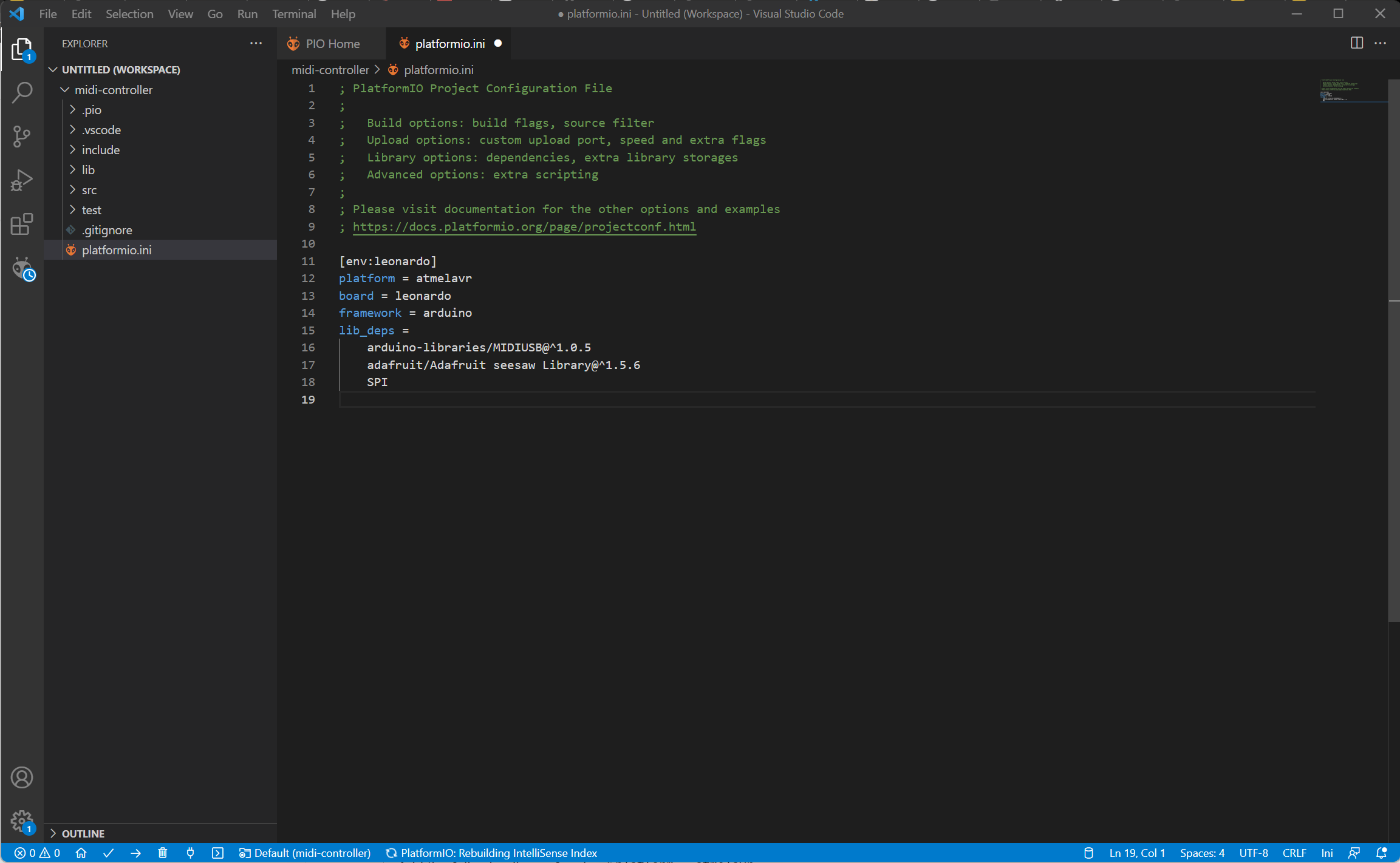
First step in coding is that we need all the custom libraries that this project will use. For us, it is just a matter of adding a few lines of code inside the platformio.ini file.
Add the following lines of code at the end of the platformio.ini file:
lib_deps = arduino-libraries/MIDIUSB@^1.0.5 adafruit/Adafruit seesaw Library@^1.5.6 SPI
Once you have that added, you are ready to write the program.
The code is split up into three modules:
- main
- midi
- controller
The main module handles the overall flow of the program. It is the module that controls everything.
The midi module handles all the communication between the computer and the Arduino
The controller module handles the communication between the Arduino and the Adafruit Seesaw board.
Each module has 2 files, a source file and a header file. The header file tells the computer what is inside the source file (think of it as a table of contents). The source file is where the actual code is.
When you created a new project, Visual Studio Code already created a main.cpp file. This is the source file for the main module.
The next step is to create the other two modules.
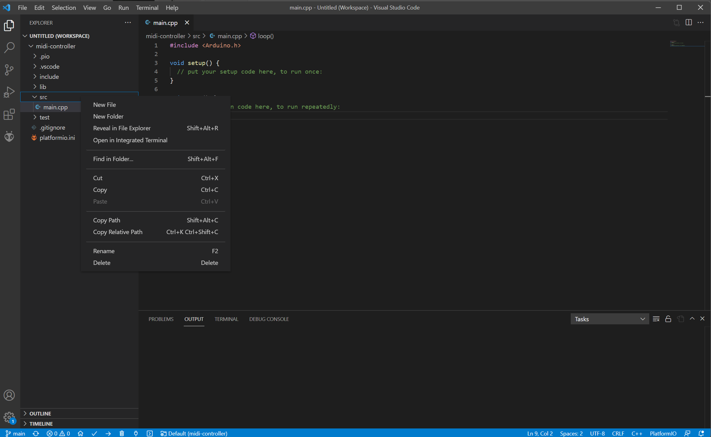
First make two new files in the src folder. You do this by right clicking on the src folder on your left side of Visual Studio Code (refer to the image). Call that new file "midi.cpp".
Then inside that file we need to place the following code:
#include "main.h"void note_on_tx(byte channel, byte pitch, byte velocity){ midiEventPacket_t noteOn = {0x09, 0x90 | channel, pitch, velocity}; MidiUSB.sendMIDI(noteOn);}void note_off_tx(byte channel, byte pitch, byte velocity){ midiEventPacket_t noteOff = {0x08, 0x80 | channel, pitch, velocity}; MidiUSB.sendMIDI(noteOff);}void note_on_rx(byte channel, byte pitch, byte velocity){ trellis.pixels.setPixelColor(map(pitch, 36, 51, 1, 16), Wheel(map(velocity, 0, 127, 0, 255))); trellis.pixels.show();}void note_off_rx(byte channel, byte pitch, byte velocity){ trellis.pixels.setPixelColor(map(pitch, 36, 51, 1, 16), 0); trellis.pixels.show();}void midi_header(midiEventPacket_t rx){ switch (rx.header) { case 0: break; // No pending events case 0x9: note_on_rx( rx.byte1 & 0xF, // channel rx.byte2, // pitch rx.byte3 // velocity ); break; case 0x8: note_off_rx( rx.byte1 & 0xF, // channel rx.byte2, // pitch rx.byte3 // velocity ); break; default: Serial.print("Unhandled MIDI message: "); Serial.print(rx.header, HEX); Serial.print("-"); Serial.print(rx.byte1, HEX); Serial.print("-"); Serial.print(rx.byte2, HEX); Serial.print("-"); Serial.println(rx.byte3, HEX); }}This code may seem overwhelming but basically, it waits for a MIDI packet to be sent from the computer and then translates it into commands. It also sends MIDI packets back to the computer when you press the buttons.
Next you will need to create the header file for it. Create a new file in the src folder (like how you did previously) and call it "midi.h"). Then place this code inside it:
#ifndef MIDI_H#define MIDI_H#include <MIDIUSB.h>void note_on_tx(byte channel, byte pitch, byte velocity);void note_off_tx(byte channel, byte pitch, byte velocity);void note_on_rx(byte channel, byte pitch, byte velocity);void note_off_rx(byte channel, byte pitch, byte velocity);void midi_header(midiEventPacket_t rx);#endif /* MIDI_H */
This tells the computer that these are the functions that this modules has.
Next we will do the same thing for the controller module. Create a new file called "controller.cpp" and paste the following code inside it:
#include "main.h"// define a callback for key pressesTrellisCallback blink(keyEvent evt){ // Check is the pad pressed? if (evt.bit.EDGE == SEESAW_KEYPAD_EDGE_RISING) { trellis.pixels.setPixelColor(evt.bit.NUM, Wheel(map(evt.bit.NUM, 0, trellis.pixels.numPixels(), 0, 255))); // on rising note_on_tx(1, map(evt.bit.NUM, 1, 16, 36, 51), 127); // Channel 0, middle C, normal velocity MidiUSB.flush(); } else if (evt.bit.EDGE == SEESAW_KEYPAD_EDGE_FALLING) { // or is the pad released? trellis.pixels.setPixelColor(evt.bit.NUM, 0); // off falling note_off_tx(1, map(evt.bit.NUM, 1, 16, 36, 51), 0); // Channel 0, middle C, normal velocity MidiUSB.flush(); } Serial.println(evt.bit.NUM); // Turn on/off the neopixels! trellis.pixels.show(); return 0;}int Wheel(byte WheelPos){ if (WheelPos < 85) { return trellis.pixels.Color(WheelPos * 3, 255 - WheelPos * 3, 0); } else if (WheelPos < 170) { WheelPos -= 85; return trellis.pixels.Color(255 - WheelPos * 3, 0, WheelPos * 3); } else { WheelPos -= 170; return trellis.pixels.Color(0, WheelPos * 3, 255 - WheelPos * 3); } return 0;}void activate_buttons(){ for (int i = 0; i < NEO_TRELLIS_NUM_KEYS; i++) { trellis.activateKey(i, SEESAW_KEYPAD_EDGE_RISING); trellis.activateKey(i, SEESAW_KEYPAD_EDGE_FALLING); trellis.registerCallback(i, blink); }}void activate_controller(){ if (!trellis.begin()) { Serial.println("Could not start trellis, check wiring?"); while (1) ; } else { Serial.println("NeoPixel Trellis started"); }}This code basically takes in the commands that has been decoded and outputs it to the LEDs. It also listens to the buttons and sends the command back to the midi module if a button is pressed.
After that we need to create a new file called "controller.h" with this code inside:
#ifndef CONTROLLER_H#define CONTROLLER_H#include "Adafruit_NeoTrellis.h"static Adafruit_NeoTrellis trellis;TrellisCallback blink(keyEvent evt);int Wheel(byte WheelPos);void activate_buttons();void activate_controller();#endif /* CONTROLLER_H */
Finally, after completing the two modules, we only need to create one more file. Create a new file called "main.h" and add this code to it:
#ifndef MAIN_H#define MAIN_H#include "midi.h"#include "controller.h"#endif /* MAIN_H */
Now its time to connect all the modules together. We do this by changing the main.cpp file. Erase the default code and paste the following:
#include "main.h"void setup(){ Serial.begin(115200); activate_controller(); activate_buttons();}void loop(){ midiEventPacket_t rx = MidiUSB.read(); midi_header(rx); trellis.read(); // interrupt management does all the work! delay(20); // the trellis has a resolution of around 60hz}This concludes the programming aspect of the project. If you encounter any errors or the files aren't being recognized, I have attached all the files to this step.
Testing Out Your Project
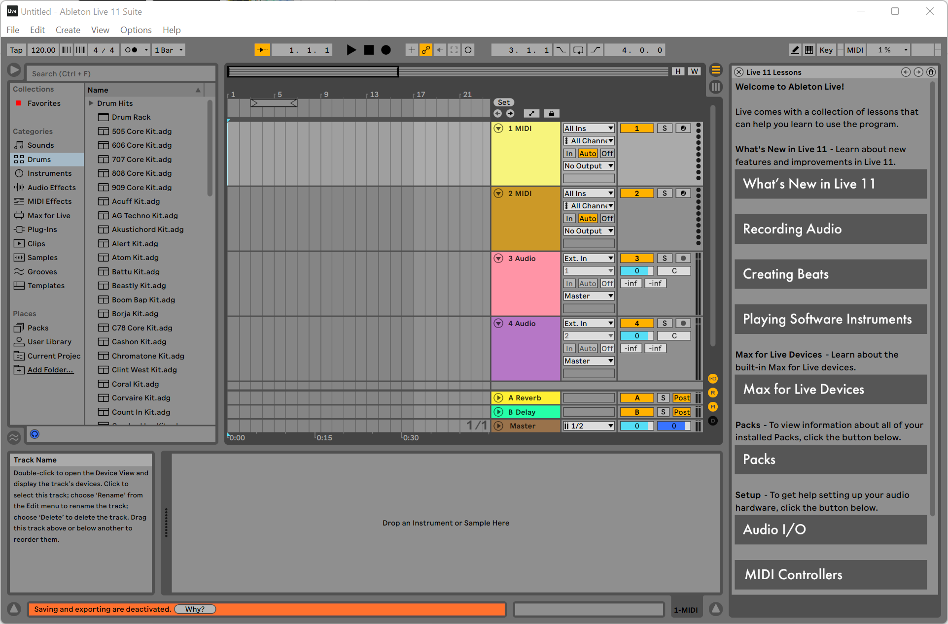
This is the final step of the project. It is time to test your MIDI controller out!
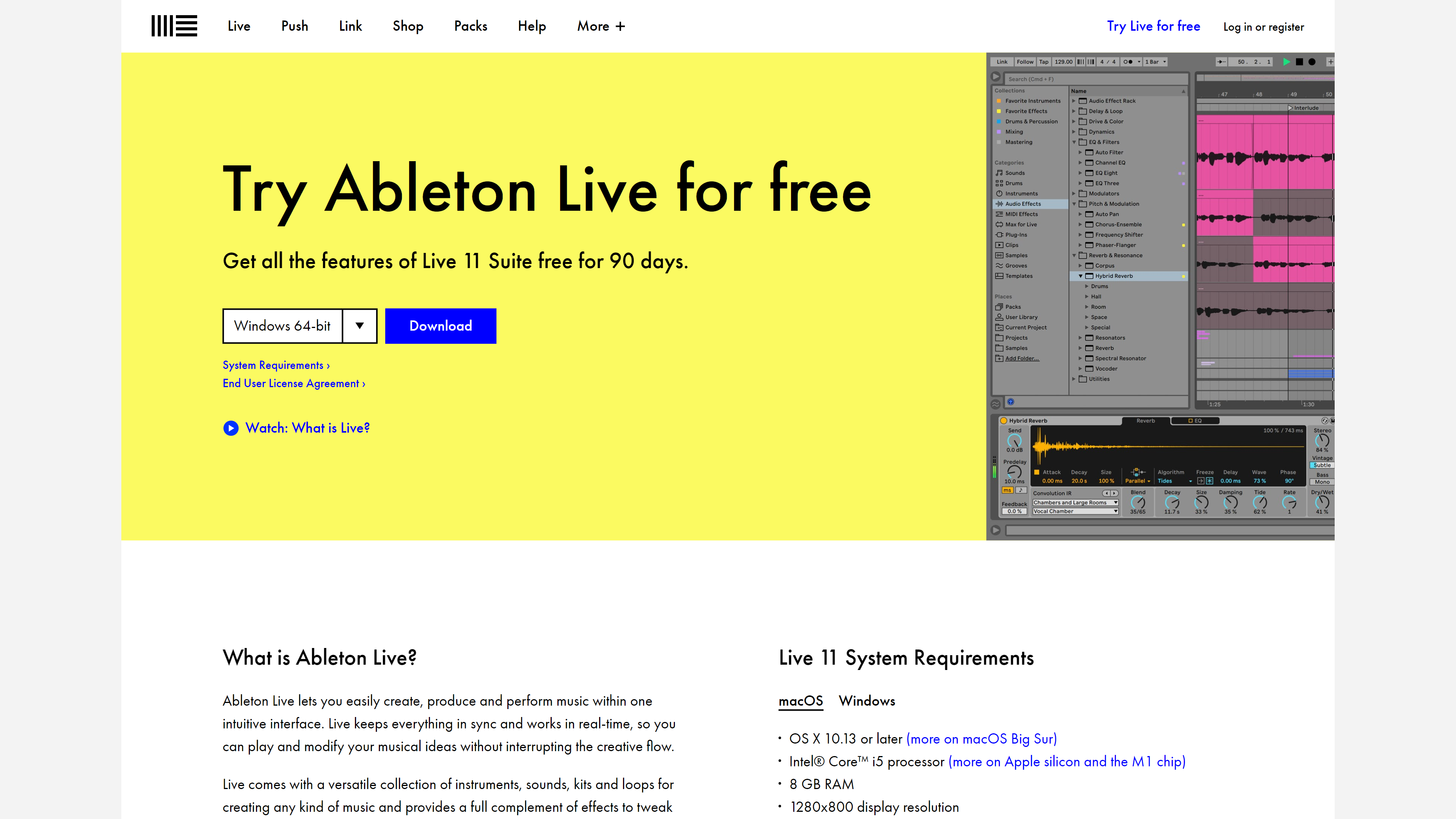
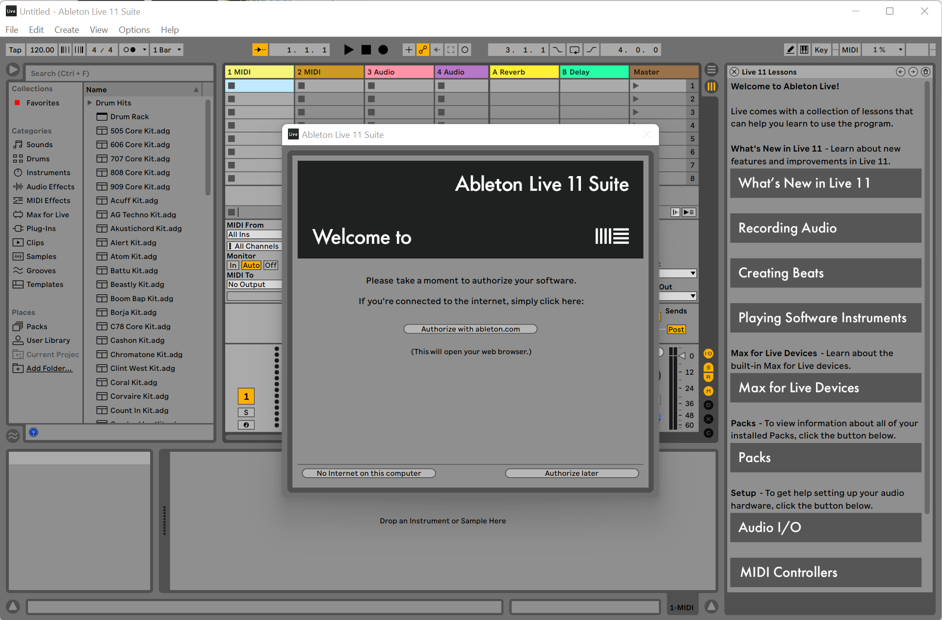
First lets download a program called Ableton Live. This program is Digital Audio Workstation (DAW). It is used to work with audio and sound effects. In our case, we will be using Ableton's midi interface. Head over to https://www.ableton.com/en/trial/ and click on download. Then follow the installation steps with all the default options selected. Once the program is installed, open it. You will see a pop up saying that you need to Authorize the program, click on Authorize later. Keep in mind that this is a free/trial software with limitations. You get all the features of Ableton Live however, you do not have the option to save your work.
Next switch to the Arrangement view (refer to the image).
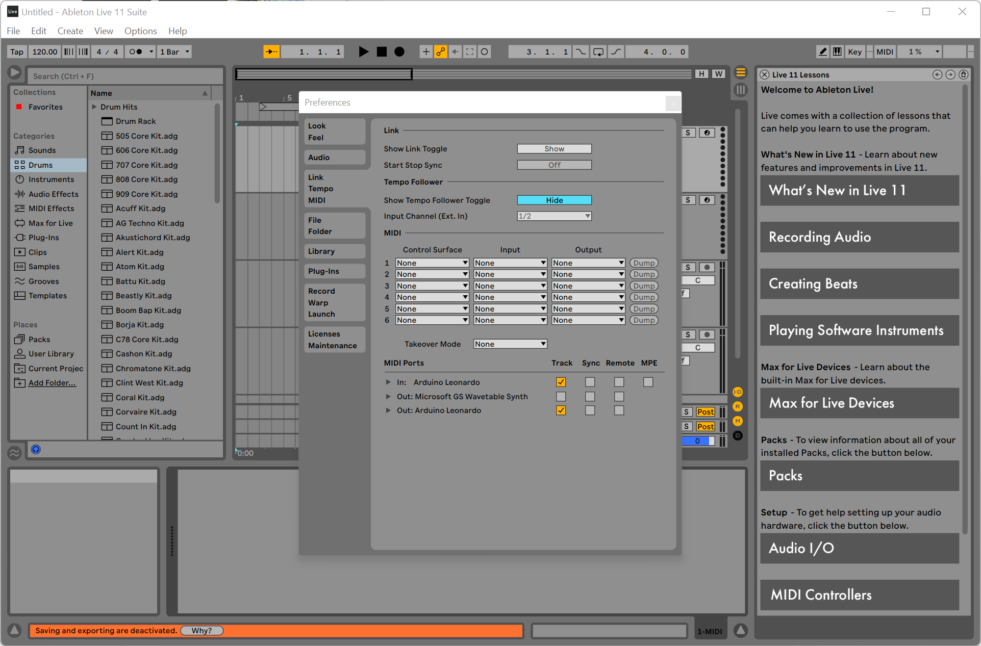
After that we need to make sure that Ableton can see the Arduino Leonardo. Use the shortcut "CTRL+," (that's control and comma at the same time) to open up Ableton Live Preferences. Make sure that you have the Arduino Leonardo Track option enabled for the input and the output to use the buttons and the LEDs (refer to the image).
Now its time to have some fun!
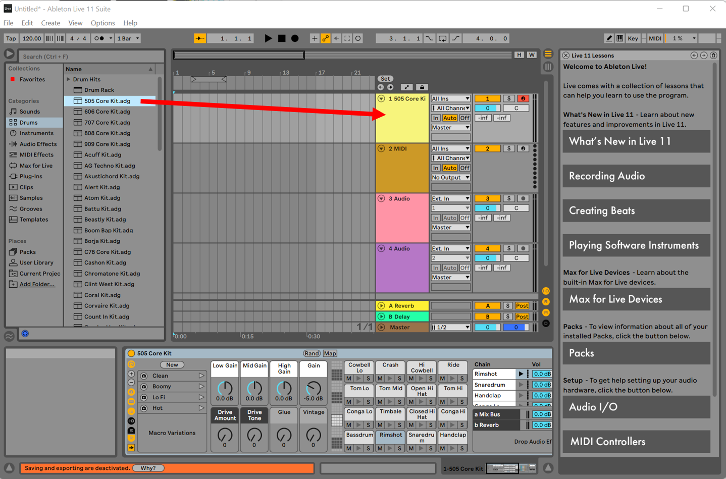
On the left side of Ableton you can see drums, drag any drum kit and drop it to any midi track (refer to the image).
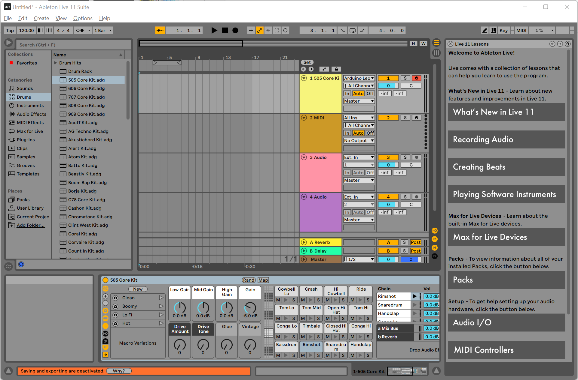
Finally, select the Arduino Leonardo as the instrument for that track (refer to the image).
Now have fun playing with the buttons! Both the buttons and the lights should work and output sound from your computer.
References
“Arduino Uno REV3,” Arduino. https://store-usa.arduino.cc/products/arduino-uno-rev3. (accessed October 8, 2021).
“Arduino Mega 2560 REV3,” Arduino. https://store-usa.arduino.cc/products/arduino-mega-2560-rev3 (accessed October 8, 2021).
“Details about MIDI 2.0™, Midi-Ci, profiles and Property Exchange,” The MIDI Association, 2021. https://www.midi.org/midi-articles/details-about-midi-2-0-midi-ci-profiles-and-property-exchange. (accessed October 8, 2021).
M. Hahn , “What is Midi? how to use the most powerful tool in music,” LANDR. https://blog.landr.com/what-is-midi/. (accessed October 8, 2021).
“Arduino Leonardo with Headers,” Arduino. https://store-usa.arduino.cc/products/arduino-leonardo-with-headers. (accessed November 3, 2021).
Shawn, “Arduino Leonardo Guide - Overview, and uno comparison,” Latest Open Tech From Seeed, 20-Nov-2019. [Online]. Available: https://www.seeedstudio.com/blog/2019/11/15/arduino-leonardo-guide-overview-and-uno-comparison/. (Accessed: 06-Nov-2021).
L. Ada, “Adafruit Neotrellis,” Adafruit Learning System, 30-May-2021. [Online]. Available: https://learn.adafruit.com/adafruit-neotrellis. (Accessed: 06-Nov-2021).