METAL FORMING With a 3D Printer
by JABA 3D in Workshop > Metalworking
14051 Views, 112 Favorites, 0 Comments
METAL FORMING With a 3D Printer
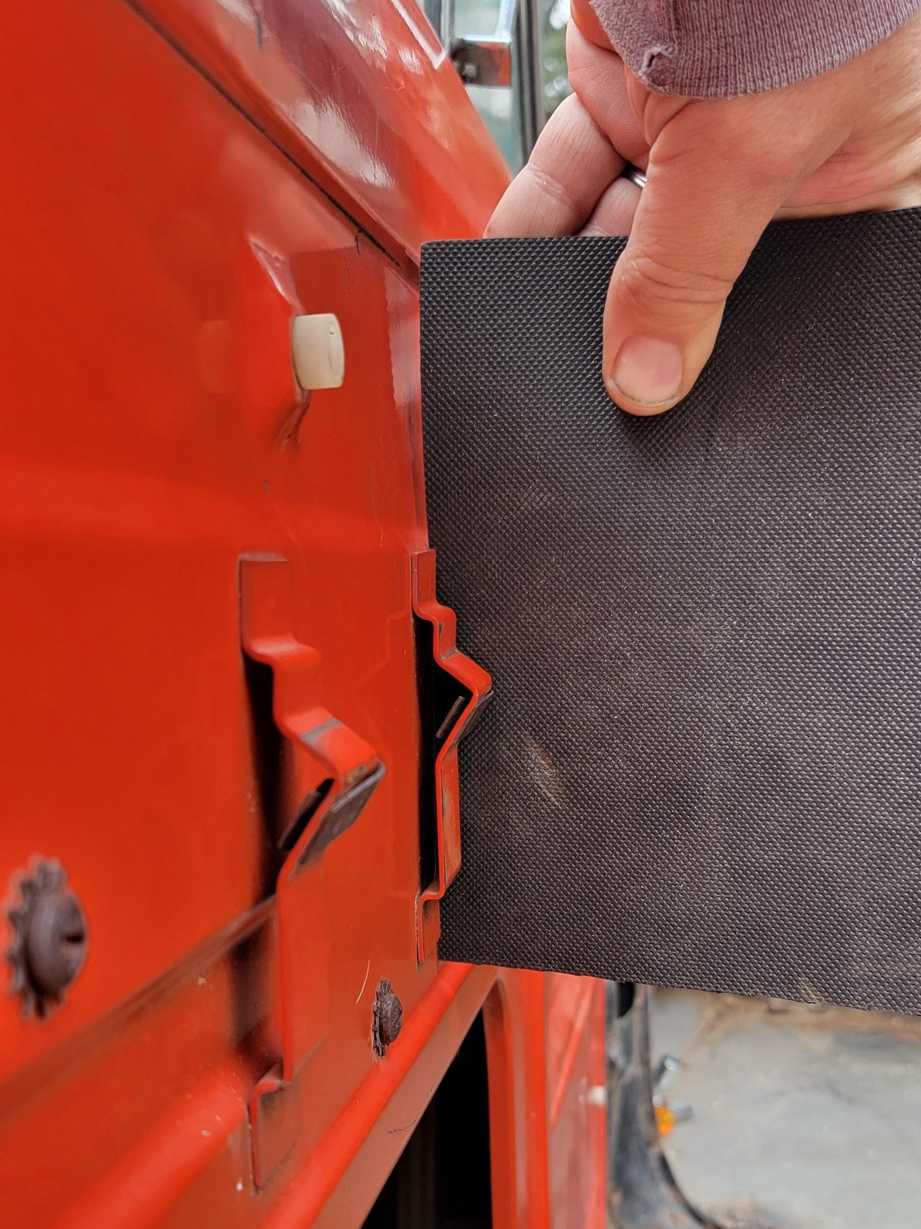
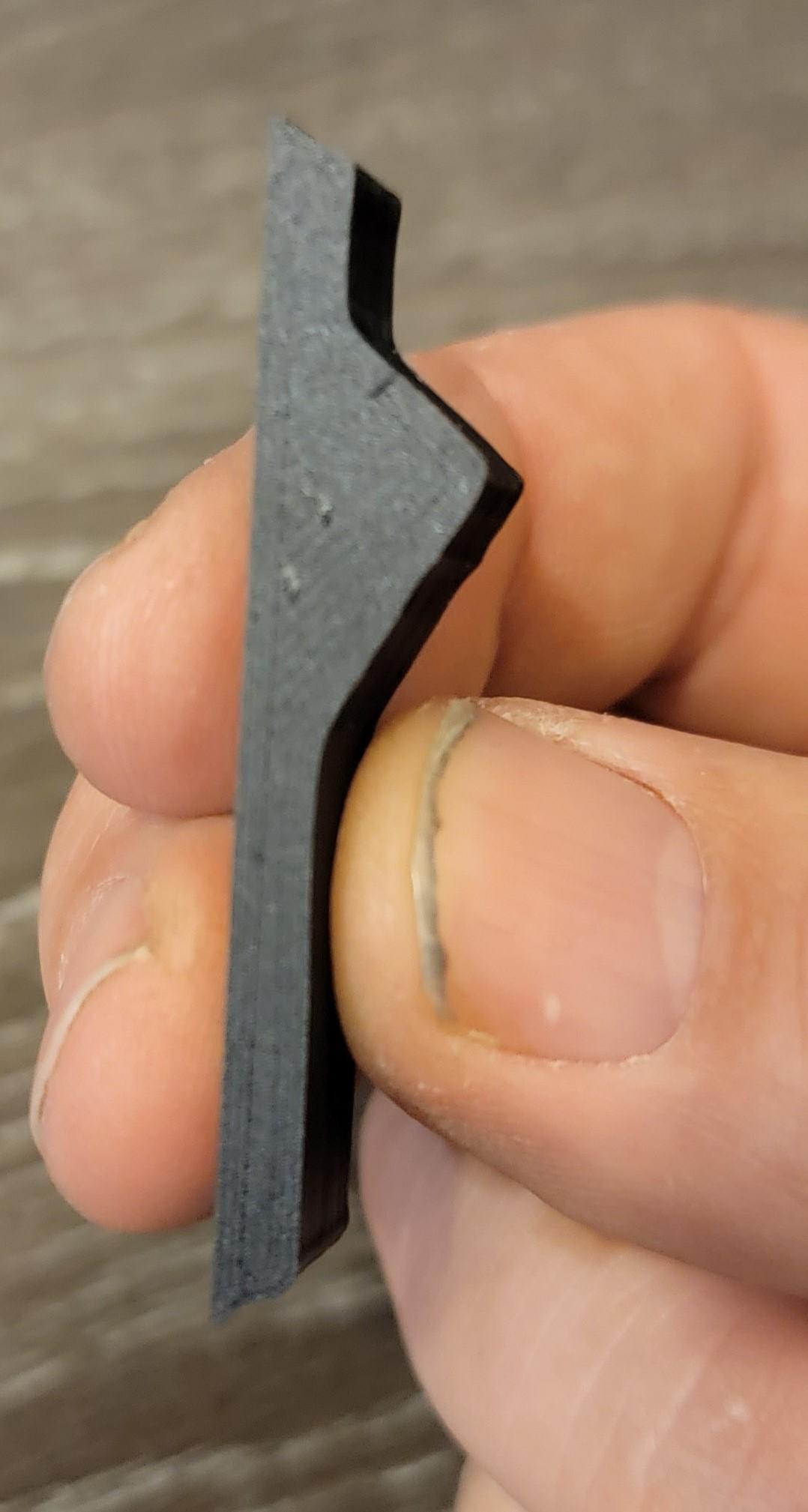
For this project, we are replicating automotive armrest brackets. To do so, we are using our 3D printers to make the dies. We will then use a 6-ton press to form the shapes.
Supplies
Supplies:
- Camera
- Image editing software (Windows Paint)
- 3D Design software (TinkerCAD)
- 3D Printer & Filament (PLA)
- Sheetmetal, 16 gauge
- 6-ton press (Harbor Freight)
- a large bench vise may work as well
Image Editing
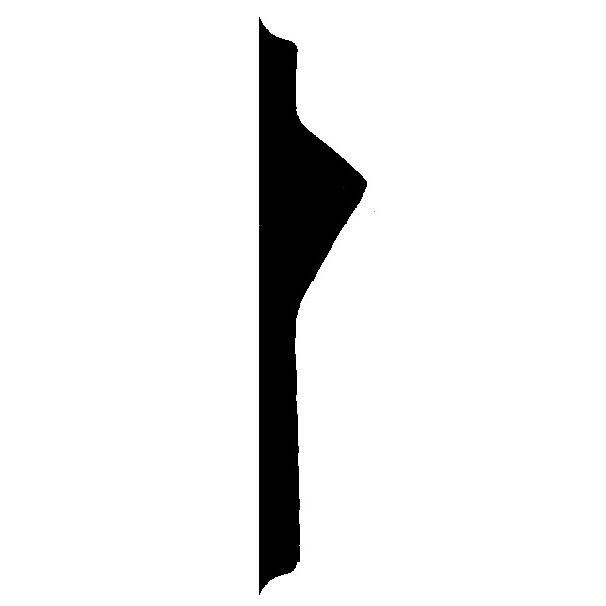
Our first step was to get a good image that we can work with for replicating the bracket. To get the image, we used a black background and took the photo as close to centered and straight on as possible. The shape that we are trying to capture here is only the dark empty space under the bracket.
Next, we edit the image to get the shape that we are after. To do this, open the image in Windows Paint and Save As 16-color Bitmap. Doing so makes it easier to remove the colors that aren’t needed, since there are only 16 colors to work with. The part that we want to keep is kept in BLACK, so we changed everything else to a WHITE background.
The process of removing the unwanted colors is relatively simple. Using the Fill Tool, change the Orange to White. Then, repeat with the Fill Tool to change any other background colors to white. If there is unwanted black touching the desired black, use the eraser and separate the blobs first, then use the fill tool to change the unwanted to white.
Zoom in and touch up the edges as needed. Save the image for the next step.
Design It
Once we have the Black and White image, we need to convert it to an SVG file. To do so, we used an Online Image to SVG Converter to convert the image to an SVG file. (https://image.online-convert.com/convert-to-svg) We left all settings as default and converted it.
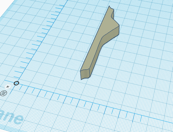
The SVG file is necessary for importing into our 3D Design software. Thankfully, TinkerCAD has the ability to convert an SVG image to a 3D object in its design environment. During importing, we shrunk the object to match the actual size of the object that we are trying to create.
Before continuing with designing the dies, we printed the object that we just imported. This was just a quick print to verify the size and shape, so we just used rough print settings for this. We then held this object up to the existing bracket to make sure that it fit behind the bracket. All fit as expected.
Now that we verified the shape, we used this as the starting point to create the die. We started with the imported shape as it has the exact dimensions that we need to fit the metal around. We first made the imported shape wider to make sure that it was wider than the metal we would be bending. We then added a base block to this shape. The base block had the the purpose of giving extra strength to the die to keep it from breaking under pressure. So, we made it extra long and extra deep. This became our base die.
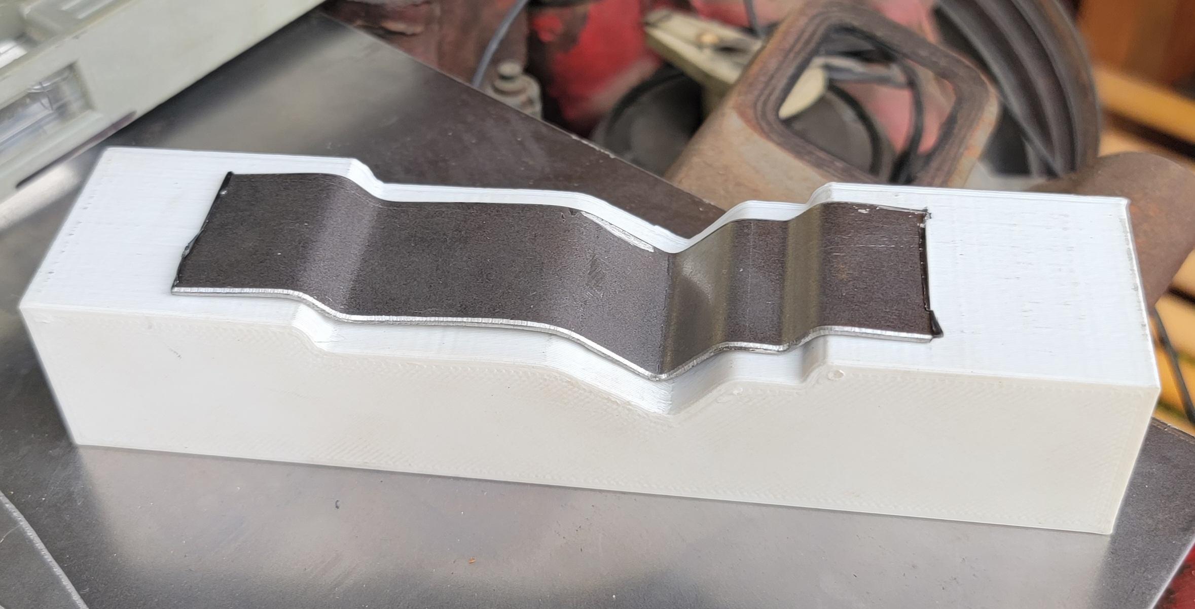
We then created the Negative side. Since the metal will need to take up space while it gets pressed, we increased the imported shape to allow for the metal to fit in. We basically increased it 1.3mm vertically, and 2.6 horizontally. This accounts for (2) thickness of metal overall on the ends. We then used this image, turned it into a "HOLE", and combined it with a block the same size as the base die. This created the Negative Die that we needed.
Print the Dies
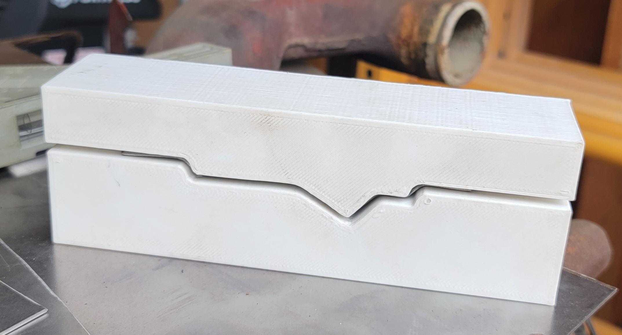
After we completed the design, it was time to print the dies. We printed this in PLA. Since we were after strength, we printed it with 10 layers on top and bottom and used 80% infill with triangle infill shape.
Print time is for the two sides required just over 8.5 hours of printing. It was printed at .34mm layer height.
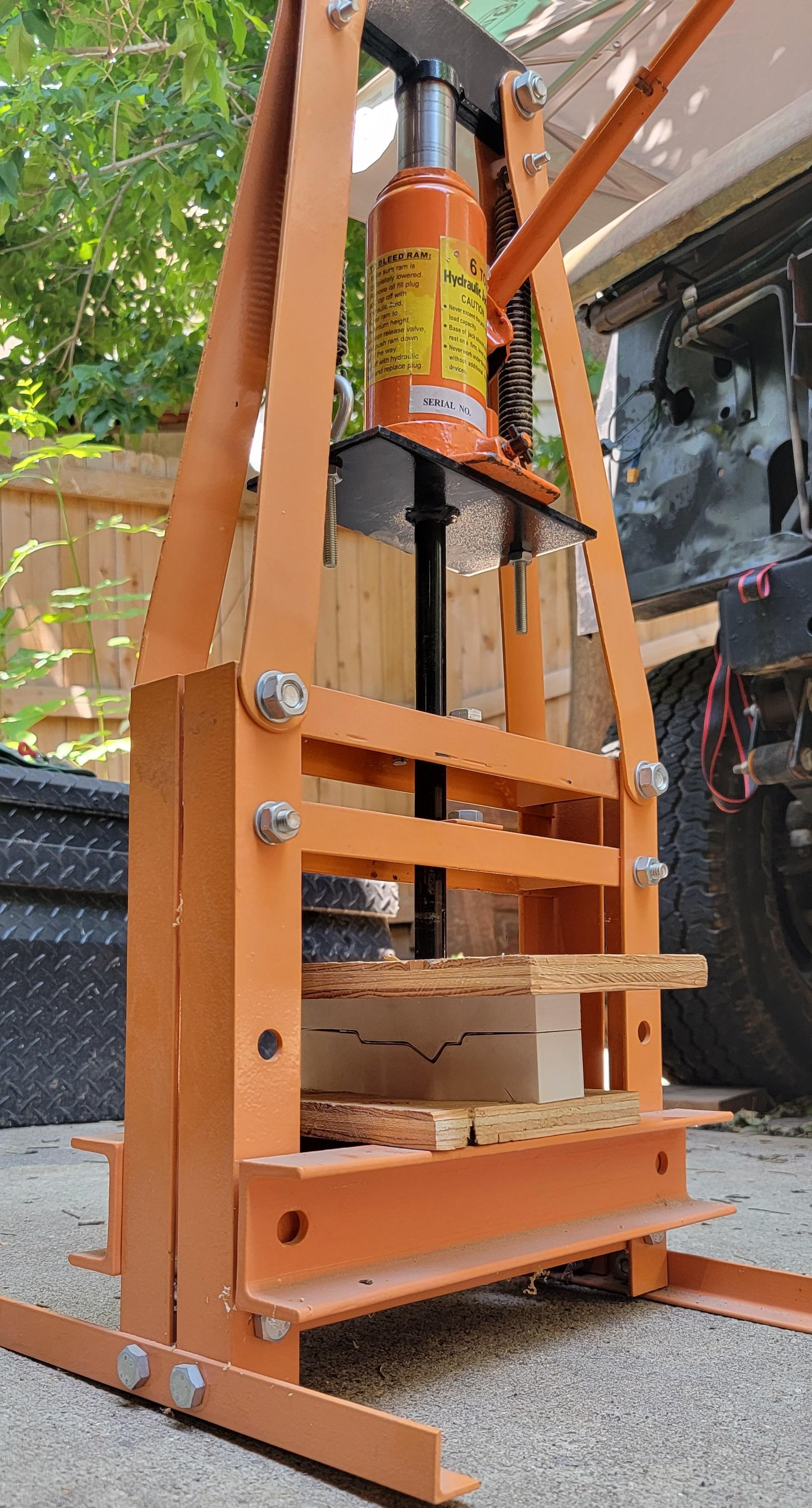
Press It
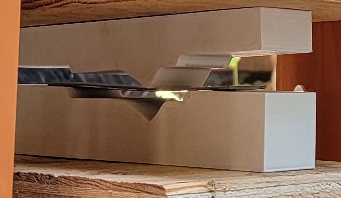
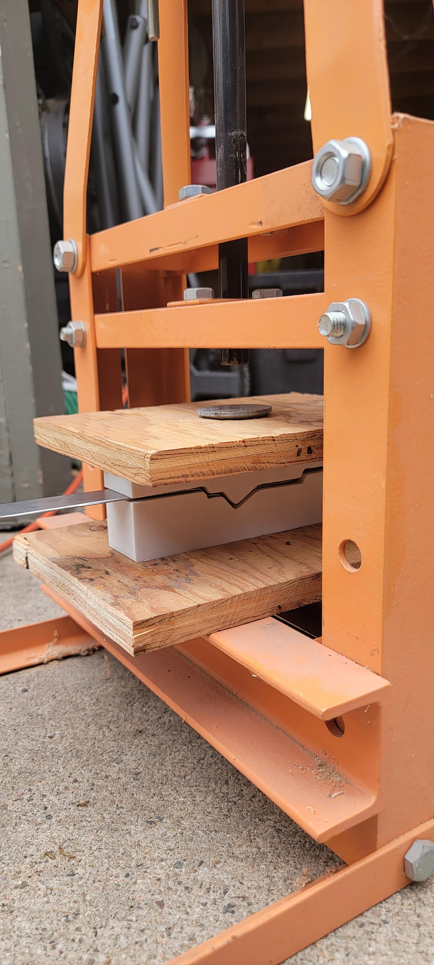
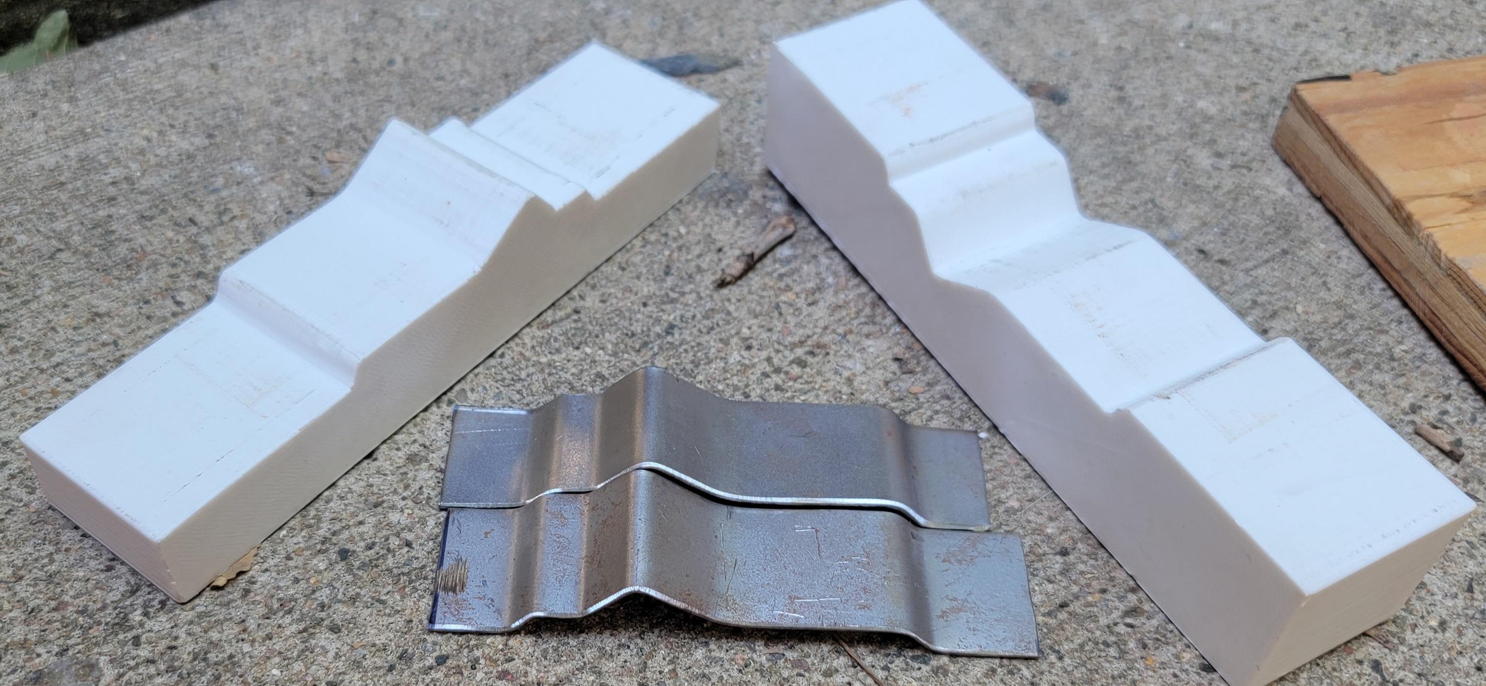
We cut the sheet metal to the same width as the original piece, but cut it extra long to make up for the loss of length from the bends. We then placed the metal in the dies and then placed it in the press. We used a 6-ton press from Harbor Freight and slowly pressed down, focusing on the center point first. As we were missing the proper plates for the press, we used plywood. This meant that we weren't applying equal pressure, so we did move the assembly around a few times in the press to allow for applying additional pressure on the ends.
Finished
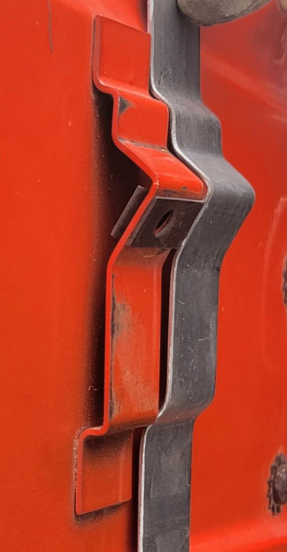
As you can see, the shape isn’t exact. But, we didn’t need it to be exact for this project. We only needed the angle of the mount to be the same and the overall heights to be the same.
If we wanted it to be exact, we would consider bending it in stages. First with a die that just bends the center and then with a die the bends all of the remaining angles. That way, the outside bends wouldn't be affected by the high point trying to pull the metal in as it is getting bent.
Conclusion: We are very pleased with the results and plan to use this process again in the future.
It should be noted that the form held up well for the two small pieces that we needed to make for our project needs. But, there is definitely a limited useful life of the print before it would deform enough to require new dies to be printed.