ME 470 Freeform Landscape Contouring
by dvanflet in Design > Software
393 Views, 0 Favorites, 0 Comments
ME 470 Freeform Landscape Contouring
.png)
The following is a tutorial video by Daniel VanFleteren that visually walks through the process of using Solidworks' free form to create difficult contouring through the example of mapping the topographical contours of a given landscape.
Downloads
Import Image to Solidworks
.png)
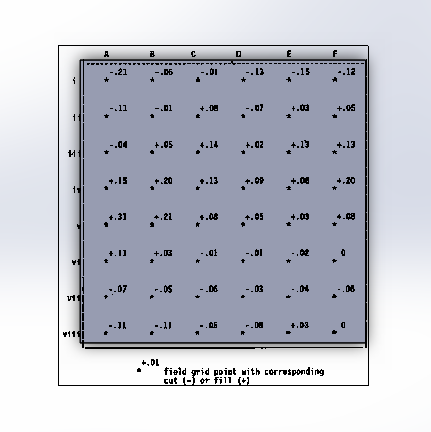
The first step in creating an accurate landscape using free form is to import an image and fit it into your Solidworks sketch or part's boundary.
Select Free Form for the Part to Be Edited
.png)
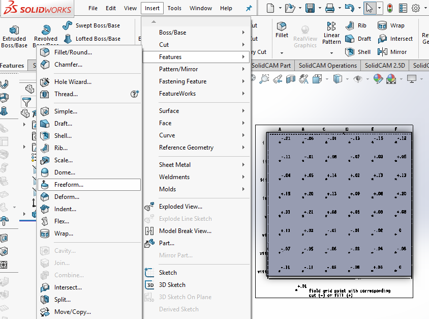
Once a Solid part is created, click insert, features, and select free form in order to prepare to create contours on the part.
Select Face to Be Edited
.png)
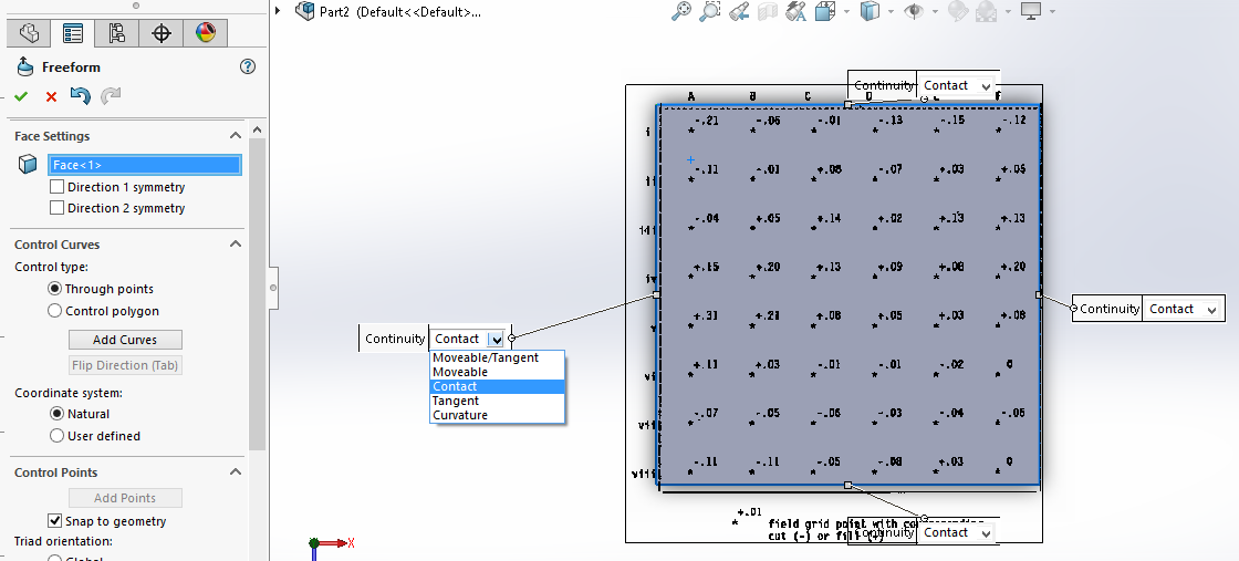
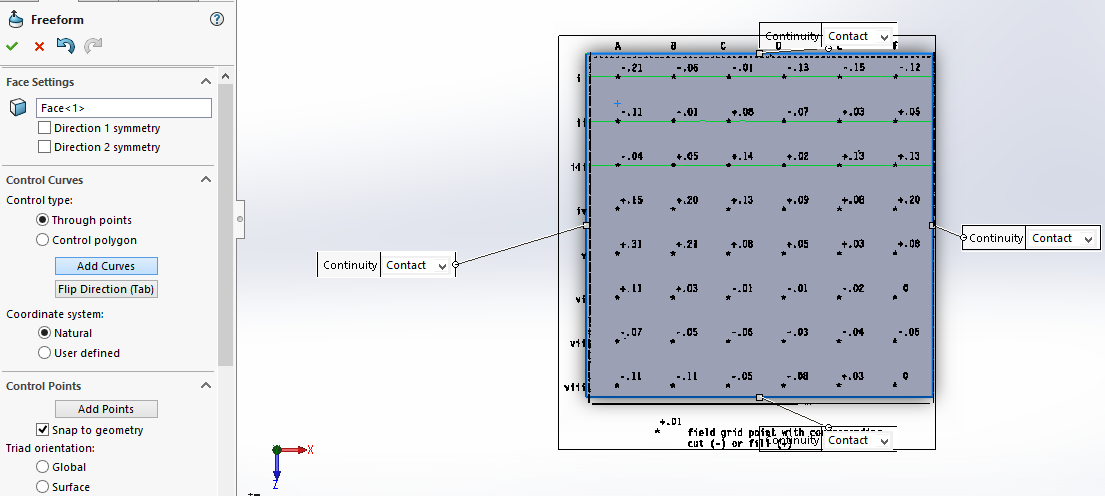
Next, the free form feature will have you select the face to be edited. When this is done four boundary labels with drop down menus will appear. Select contact for all four boundaries.
Add Horizontal Guide Curves
.png)
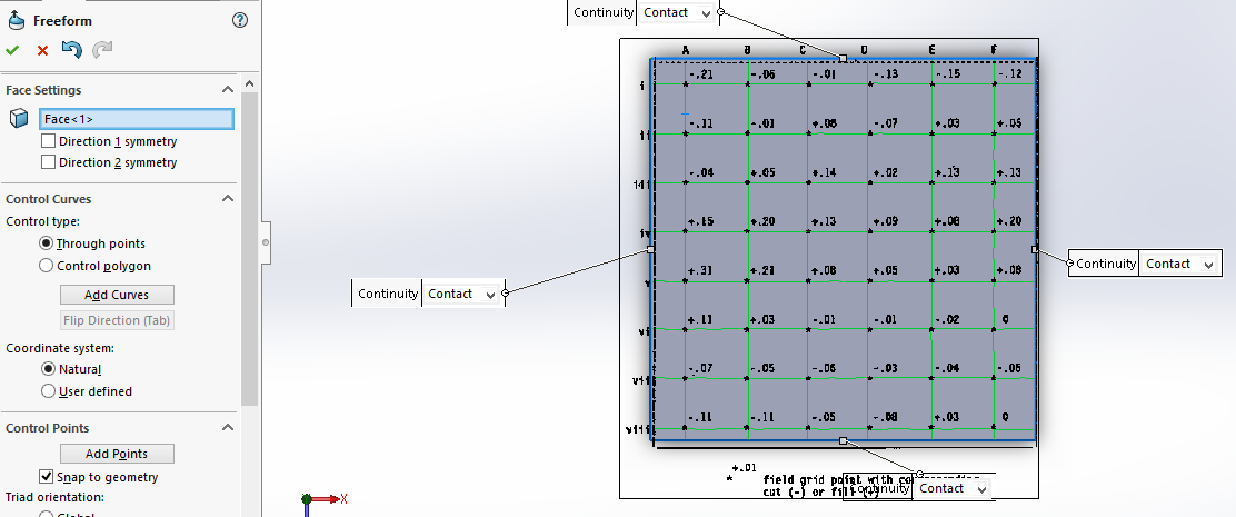
Next, select add curves, ensuring that through points is selected. Then place horizontal lines through the grid points on the inserted images.
Add Vertical Guide Curves
.png)
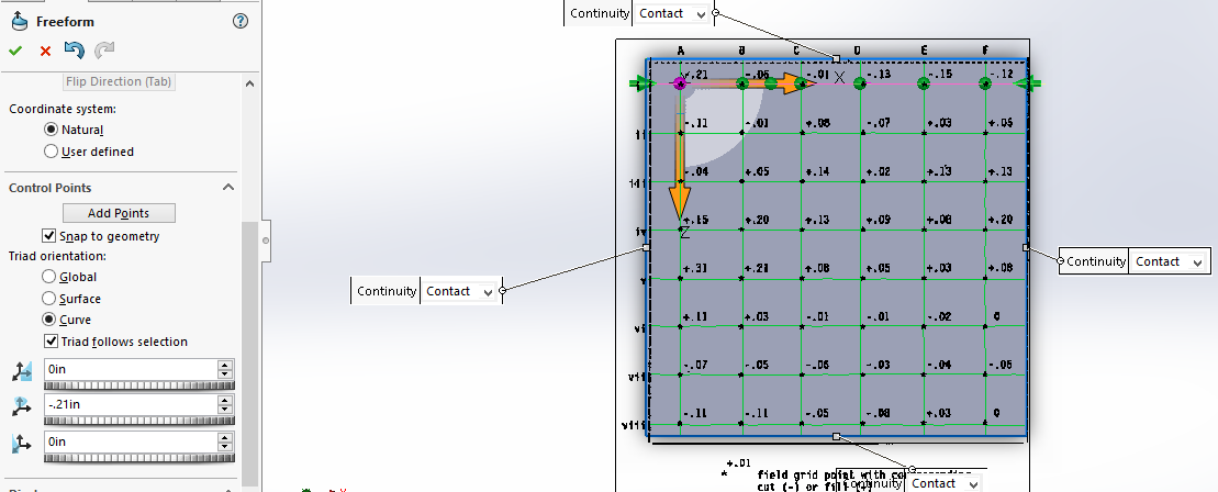
Then, click either the tab key or select Flip Direction and complete the grid through the image points using the vertical guide curve lines.
Add Points and Deform
.png)
Click the add points box and click on the horizontal or vertical curve lines. This will snap points to all grid intersections. Deselect the box add points. Then go down the line, click each point to be deformed, and enter the value listed in the grid for how much vertical displacement is needed. If sketching in the top plane this will be the deformation in the y-axis.
Improve the Visual (Optional)
.png)
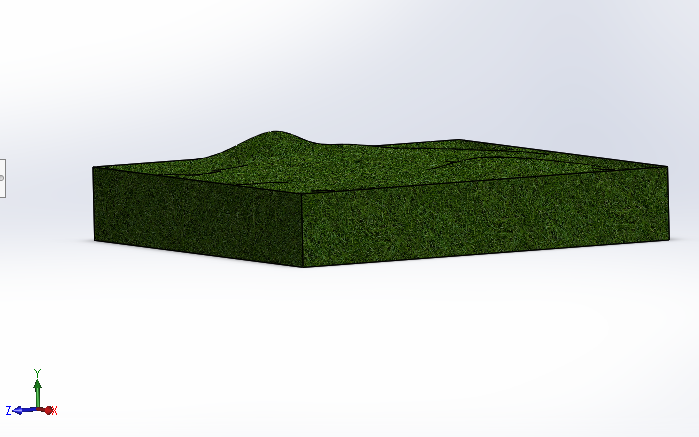
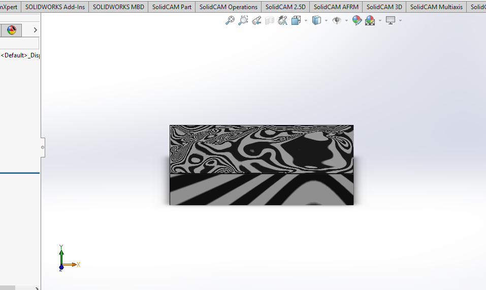
Once all the points are deformed to the amount specified in the image, click the check in the free form feature and delete the original image. To better see the contour, click view and select zebra stripes to better see the curves of the part.