MDF and Acrylic Reverse Clock
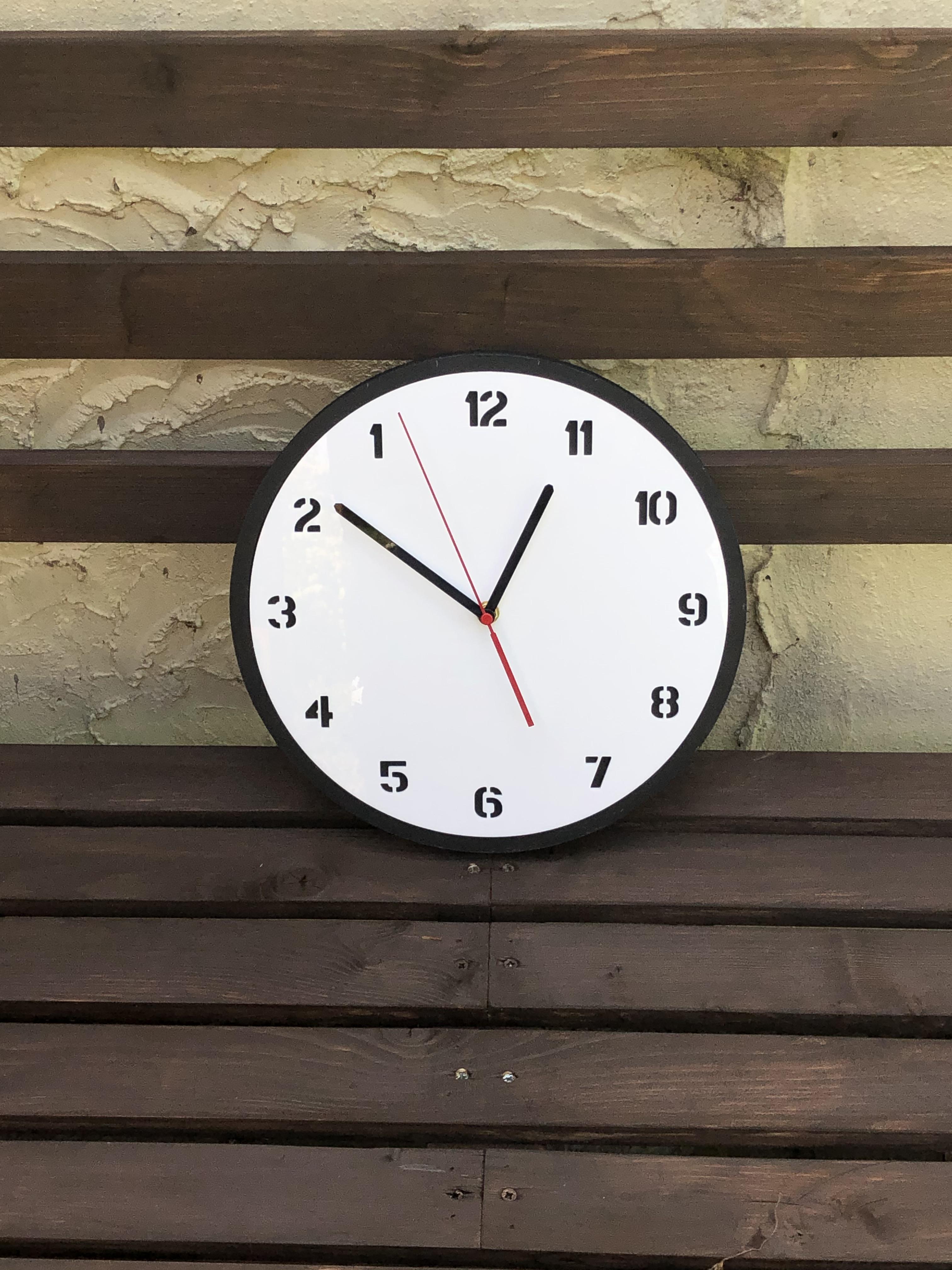

In this Instructable I will show you how I make a reverse clock using MDF and White Acrylic.
The design is carried out using Vetric cut 2D
And of course you will need to have a CNC machine.
Before starting out ensure you have all the necessary Health and Safety equipment needed to carry out the Tasks. CNC Machines can be noisy and dangerous and create a lot of dust.
As a minimum during cutting operations you will need. Safety Glasses. Ear Defenders. Dust Mask(Rated for the work you are carrying out)
Its a clock with a difference so lets get started.
Supplies
Reverse clock quartz Mechanism
MDF 19mm depth
White Acrylic 4mm
Blackboard paint
6mm and 2mm Router bits
Making a Template for the Clock Using Vetric Cut2D and First Cutting Operations
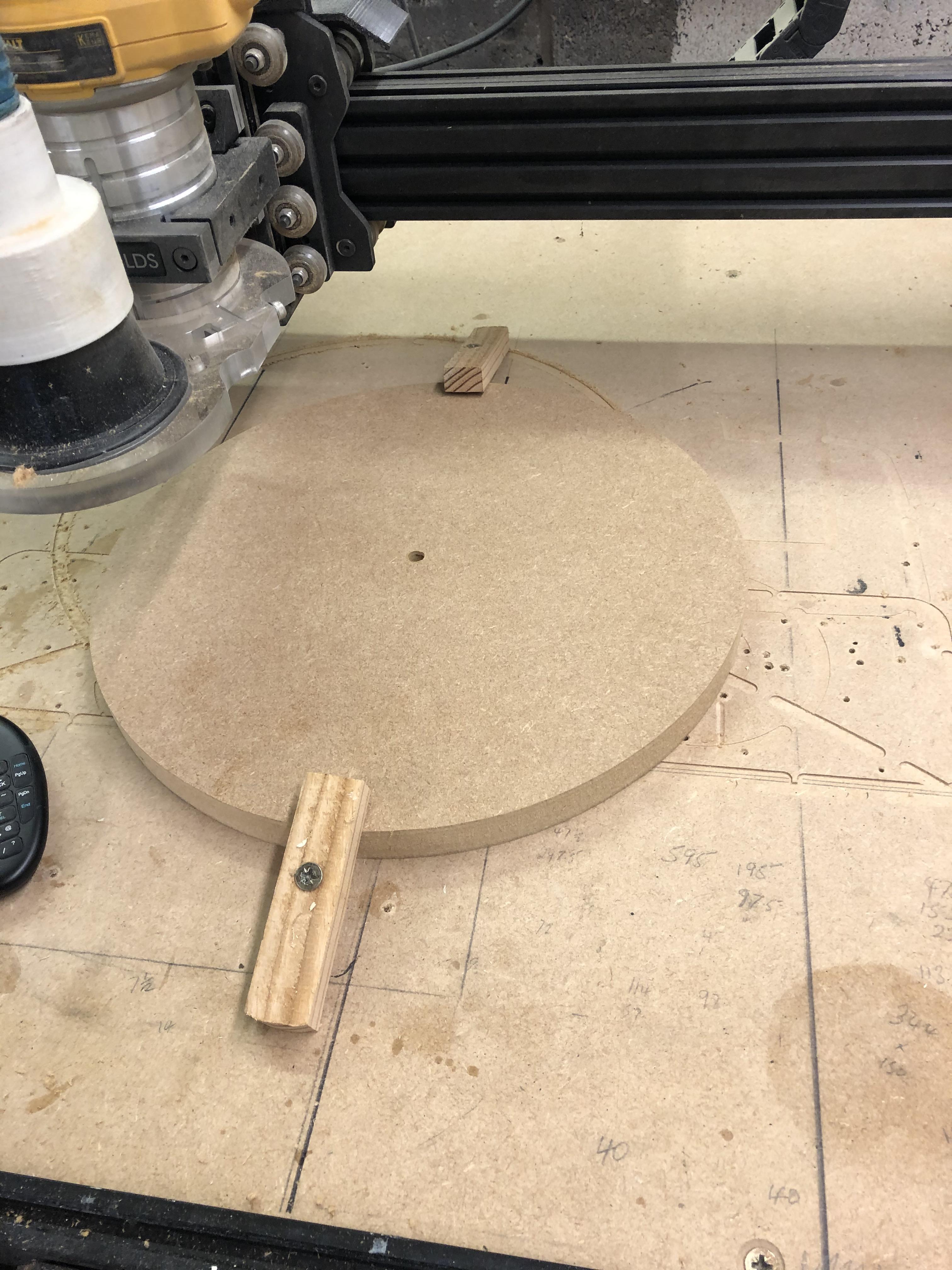
The first operation is cutting out the MDF
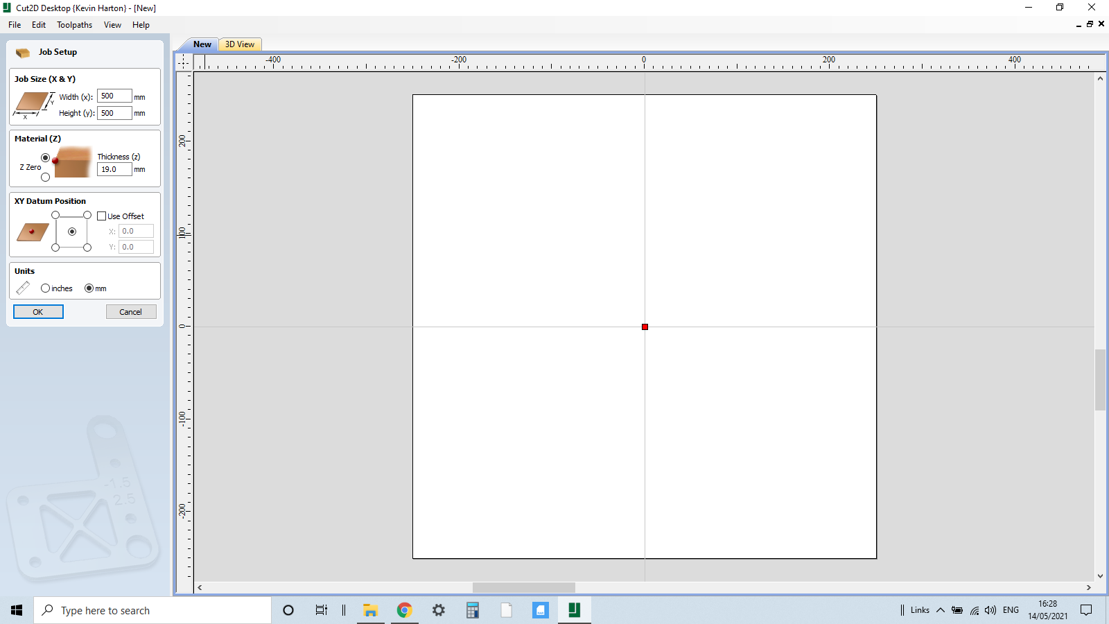
We now need to input some dimensions in Cut2D
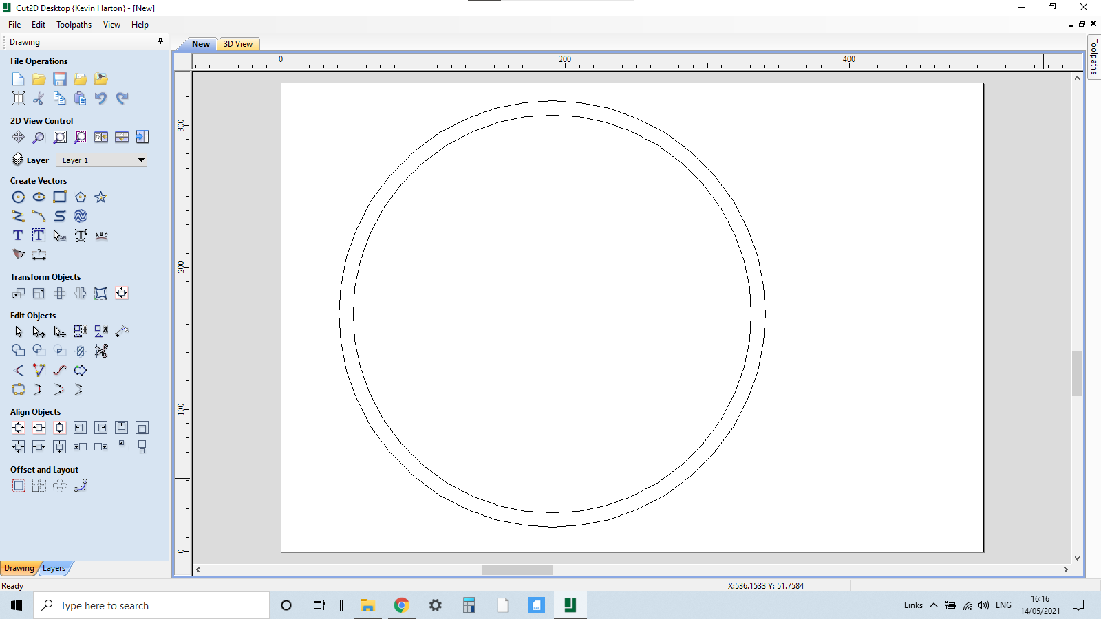
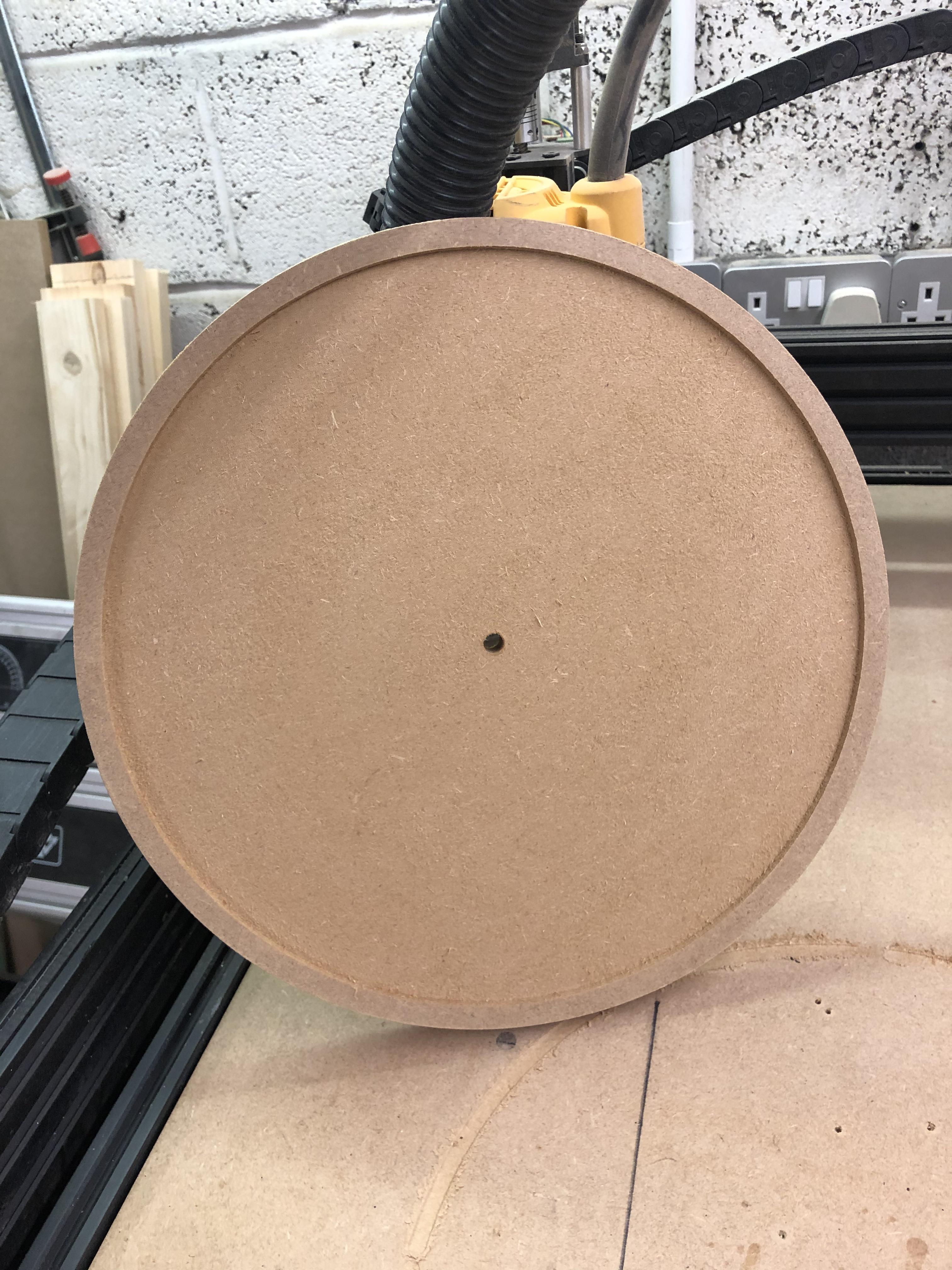
I went for an oversize piece of MDF but the clock I am making is 300mm in diameter with a 10mm offset to make a black ring around the circumference of the clock, the MDF is 18mm depth, my starting point for this operation will be the bottom left corner of the work piece.
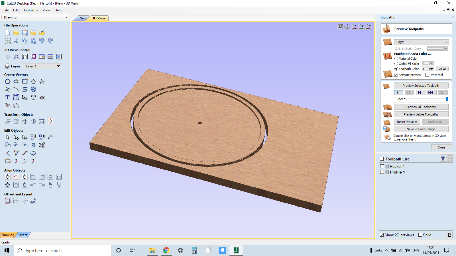
Create a circle 300mm then create a 10mm internal offset this will give us a border for the clock, also we need to create a hole for the shaft of the clock mechanism, we can click circle again and place central within the offset circle the shaft is 7.5mm so make the circle 8mm.
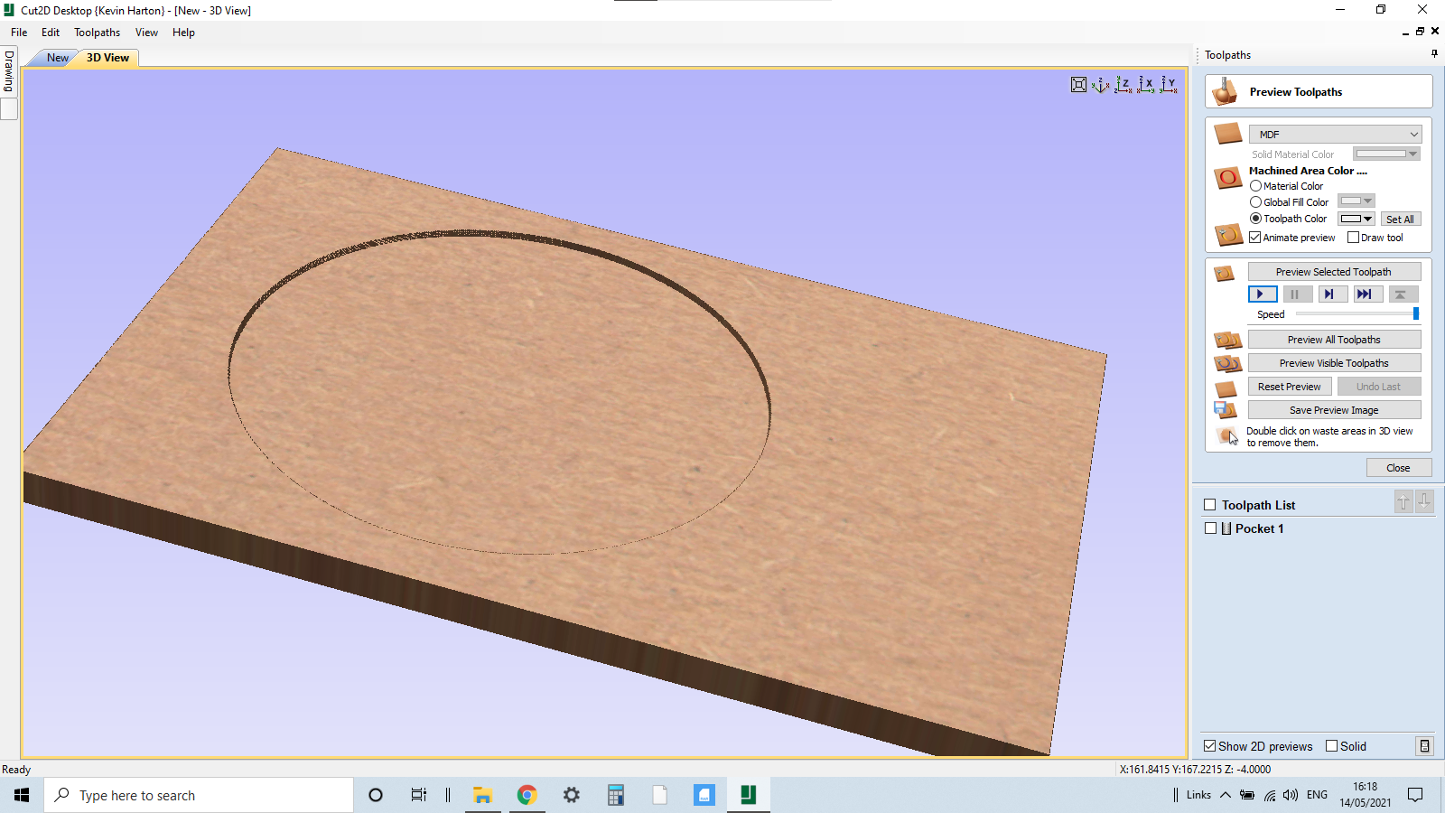
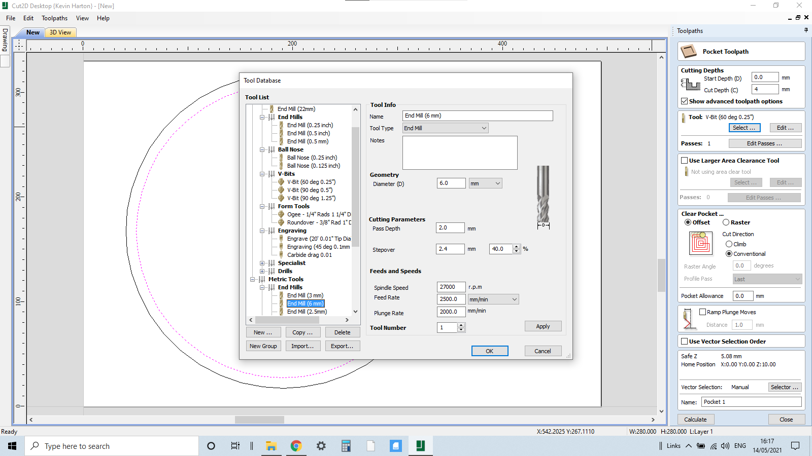
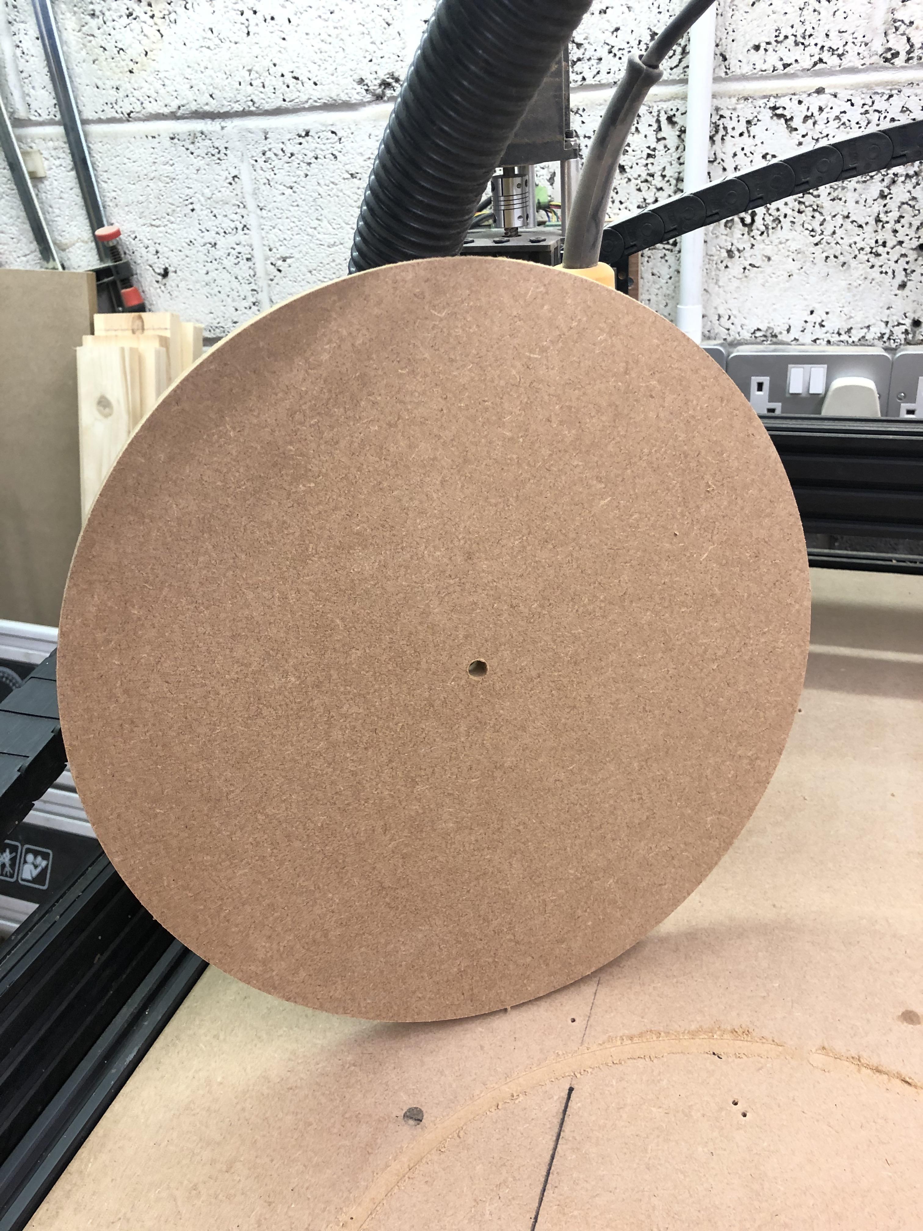
Cutting operation 1 is cutting the inner circle to a depth of 4mm, this will create a pocket for the Acrylic face of the clock.
Click on the pocket tab and highlight the inner circle, depth of cut is 4mm
We select a 6mm flat bottomed router bit
Calculate and preview the cut.
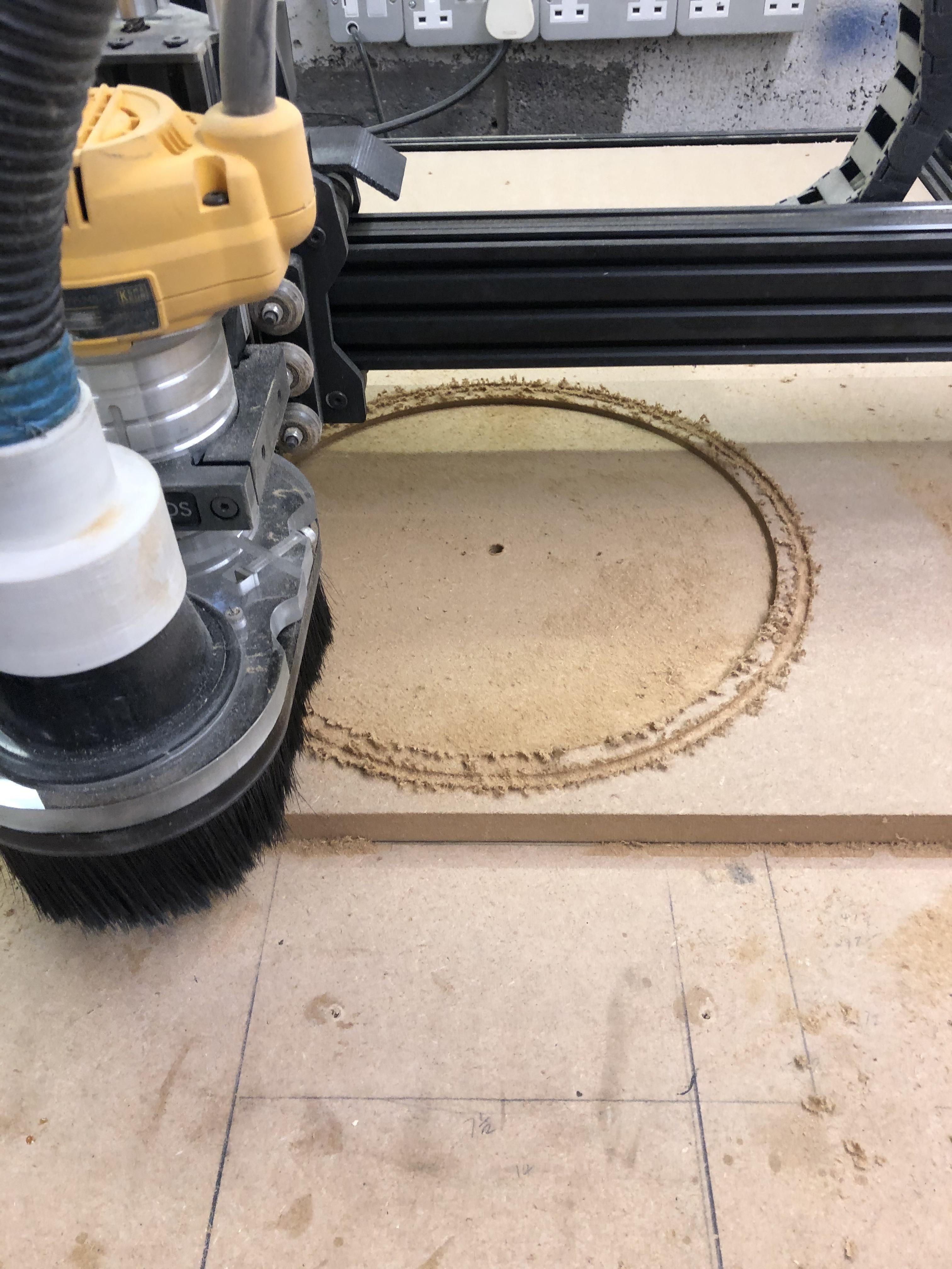
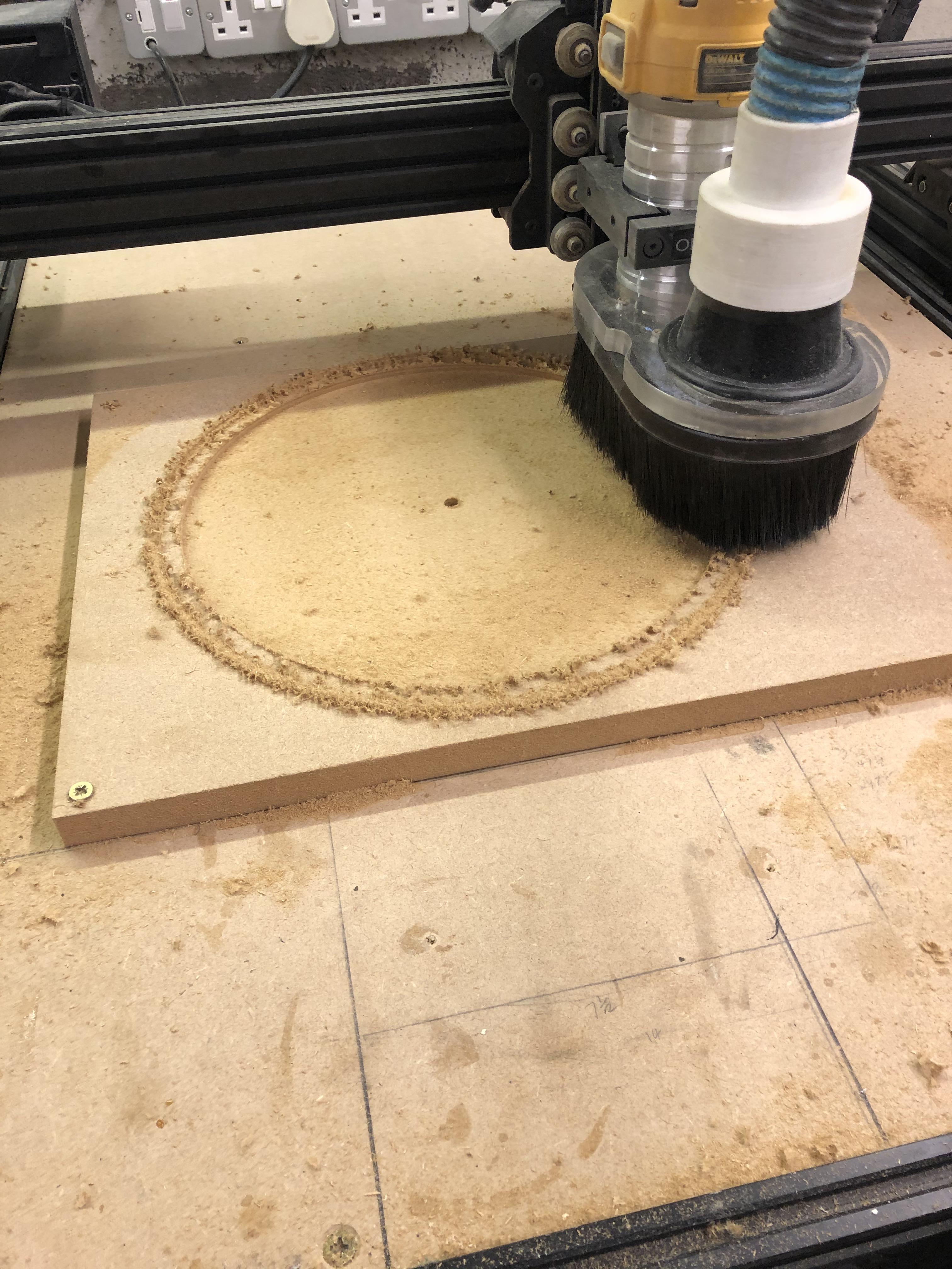
Set up the CNC machine, use the correct PPE and do the cuts.
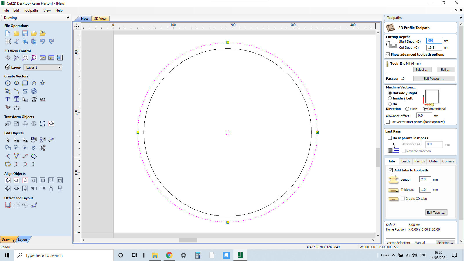
Cutting operation 2 is a profile cut for the 8mm hole in the centre of the circle, the depth will be 14.2 mm as we have already taken out 4mm.
Also at this stage we cut out the perimeter of the clock, depth is 18.3 as we need to go right through the MDF we create tabs within the profile tab to hold in place.
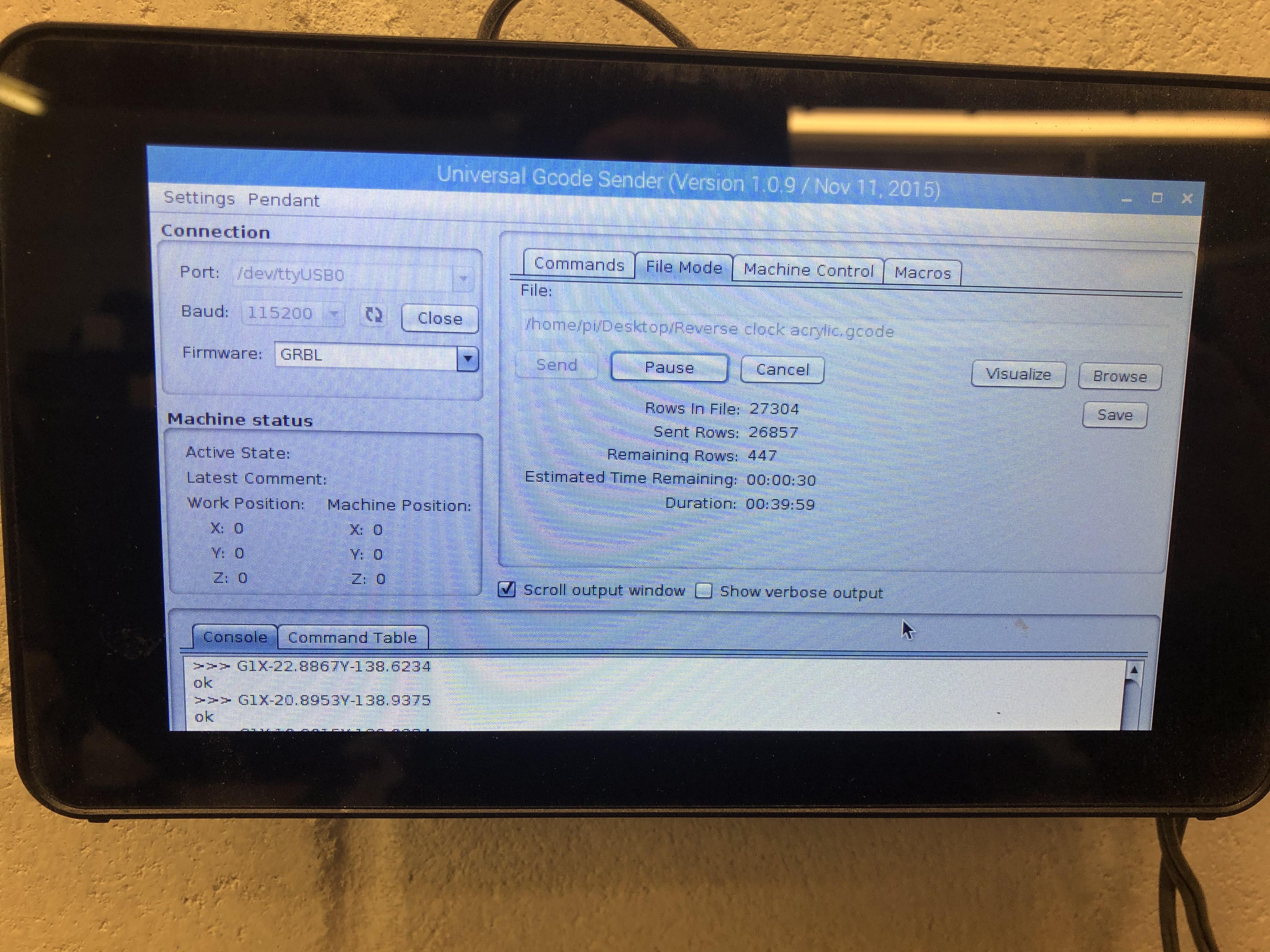
Save the cutting operations and send to the CNC Machine.
Set up the CNC machine, use the correct PPE and do the cuts.
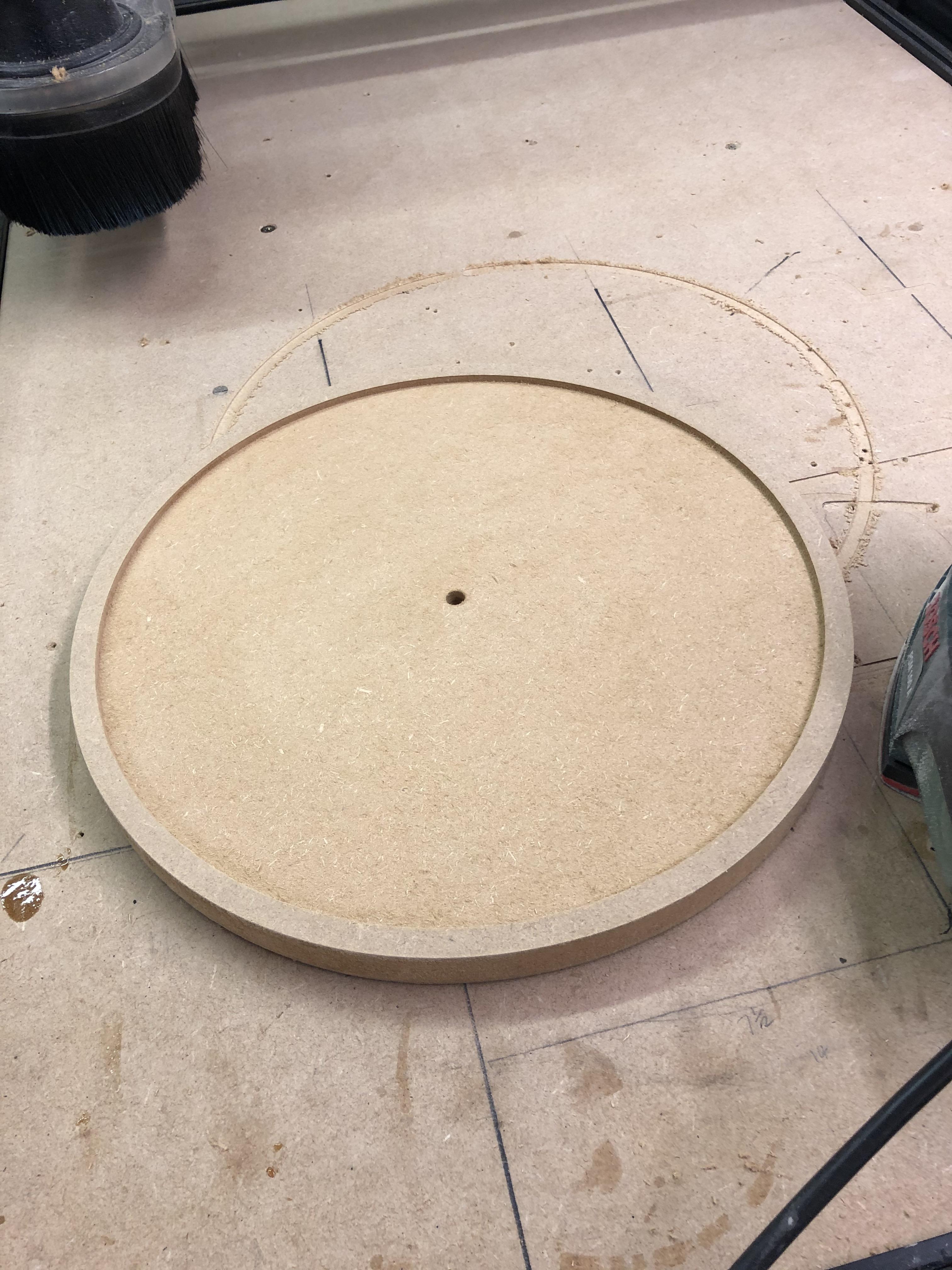
We can now remove the circle and lightly sand.
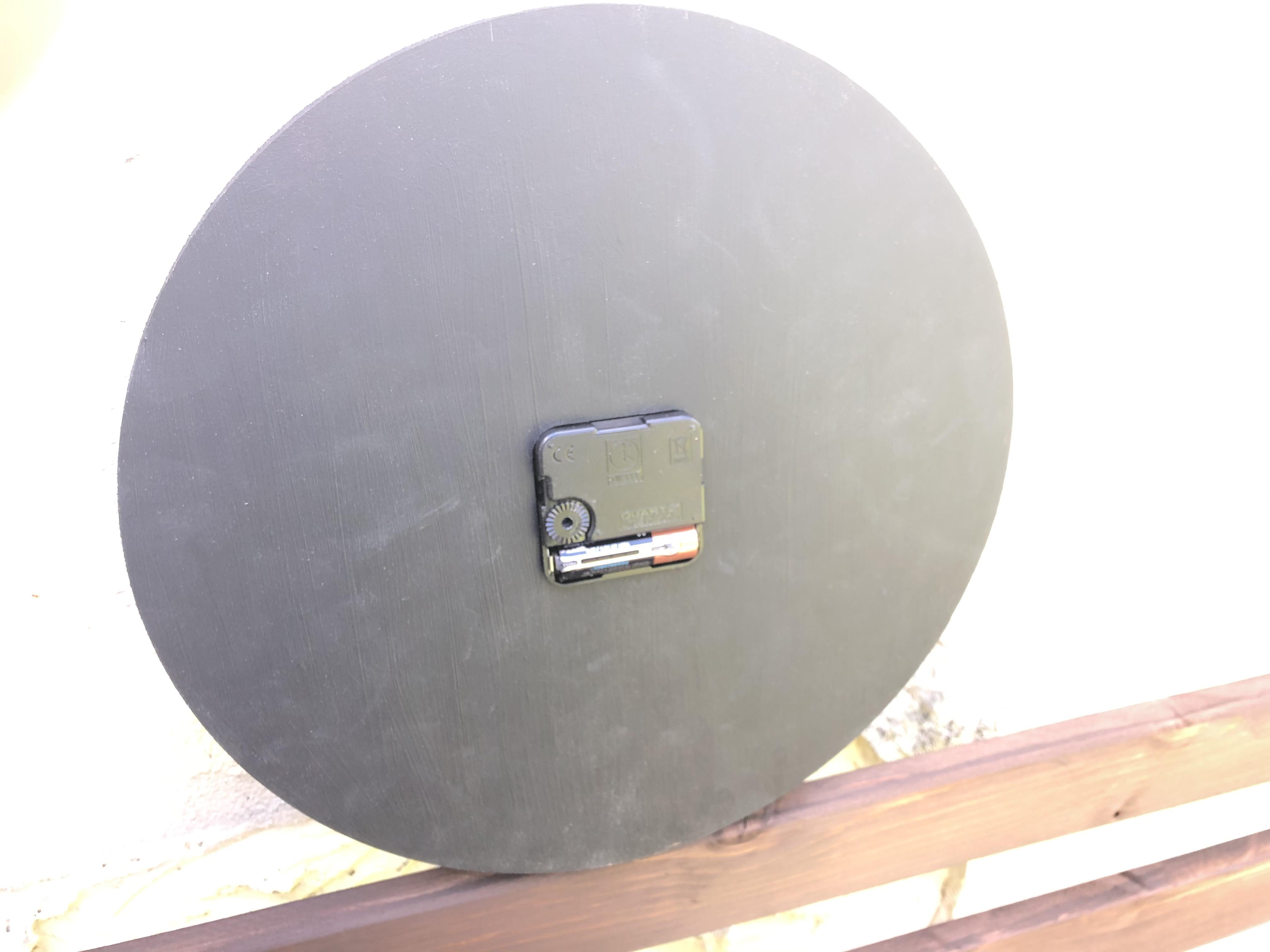
Back of the MDF Pocket for the Clock Mechanism
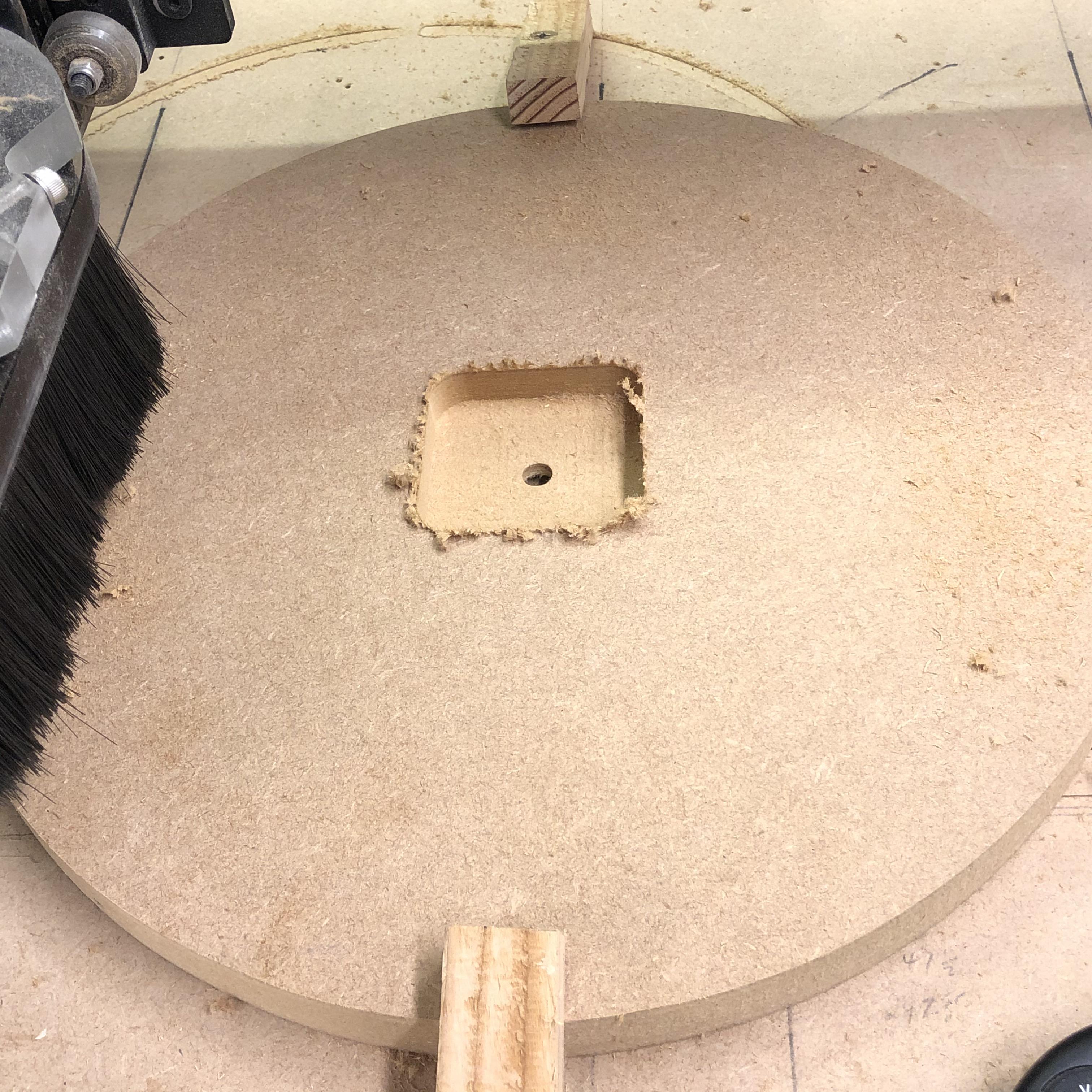
Due to the thickness of the MDF we now need to create a pocket on the back of the circle to sink the clock mechanism into so the shaft will protrude through the acrylic.
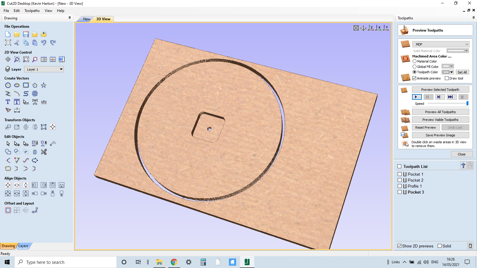
The clock mechanism is about 56mm square with rounded edges so we need to make the pocket approx 58mm square and a 10mm fillet in each corner for a snug fit.
In the set up we now need to make out starting point for CNC operations the centre of the piece
Select the square option in Cut2D create a 58mm square in the centre of the circle and use the fillet tab and create 10mm fillets.
Cutting operation 3 will be a pocket cut, depth will be 11mm and we can use the same 6mm flat bottomed router bit.
Review and save the file, send it to the CNC machine.
Clamp the already cut circle upside down on the spoilboard and centralise the bit, we already have the shaft hole cut out making this alignment easy.
Set up the CNC machine, use the correct PPE and do the cuts.
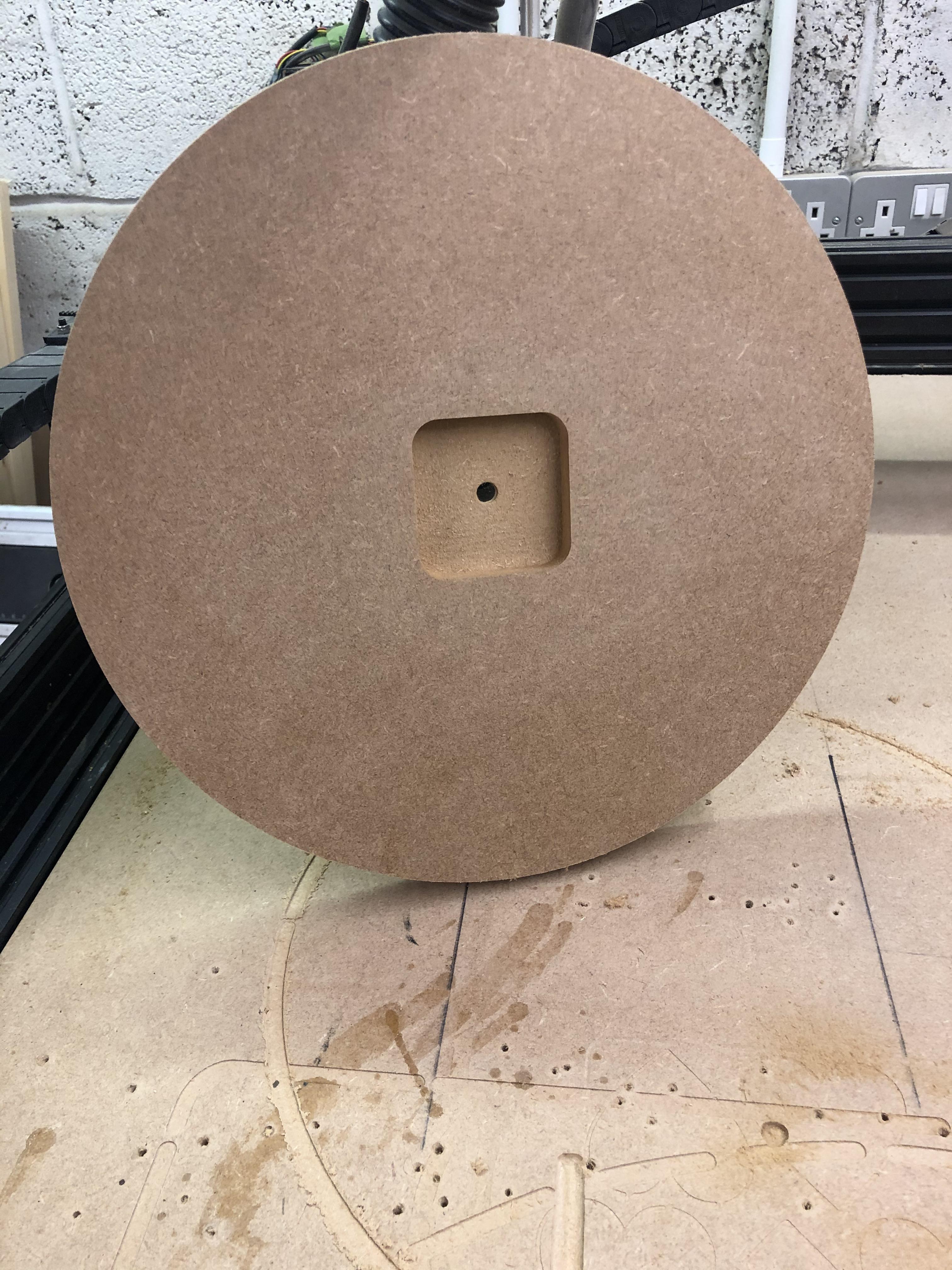
Cut out the pocket, lightly sand the area.
Finishing the Clock Base.
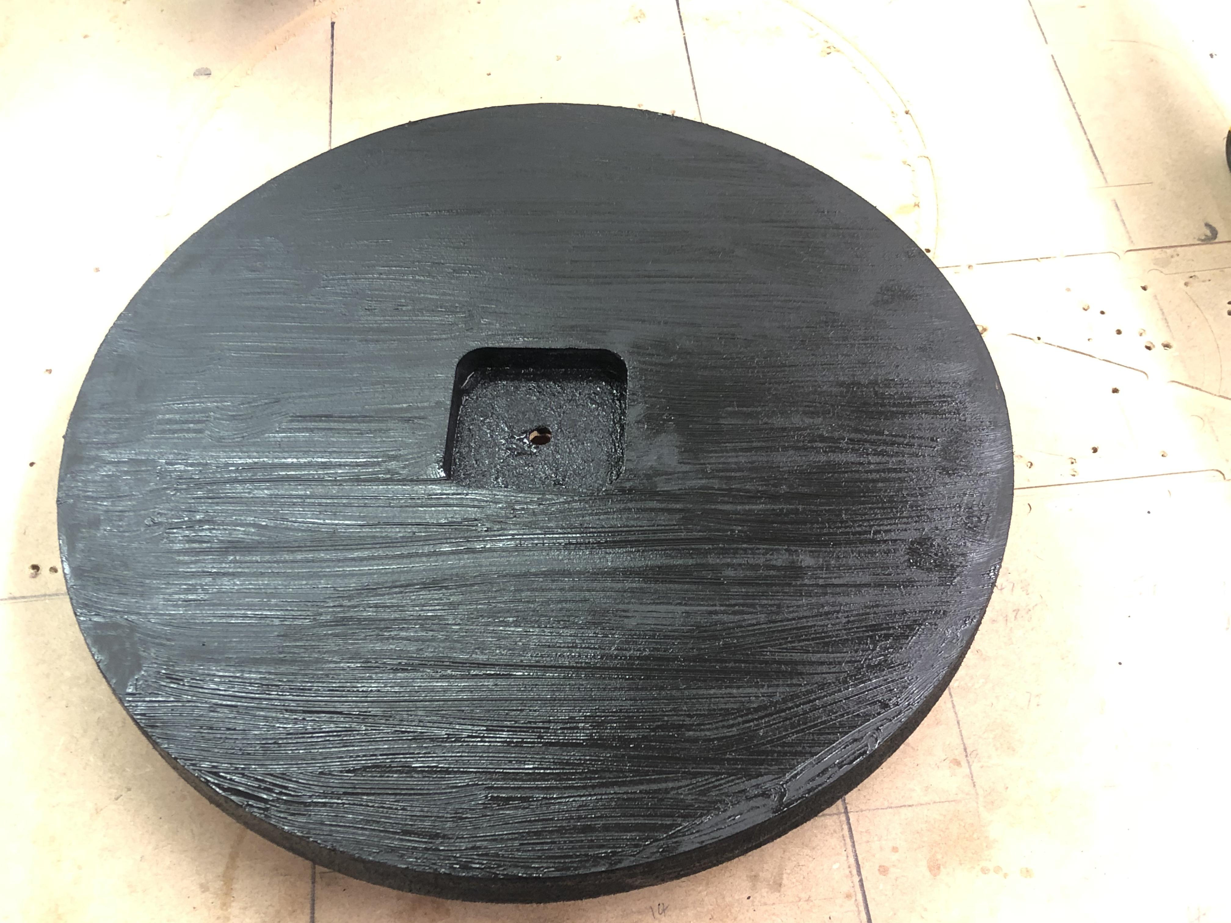
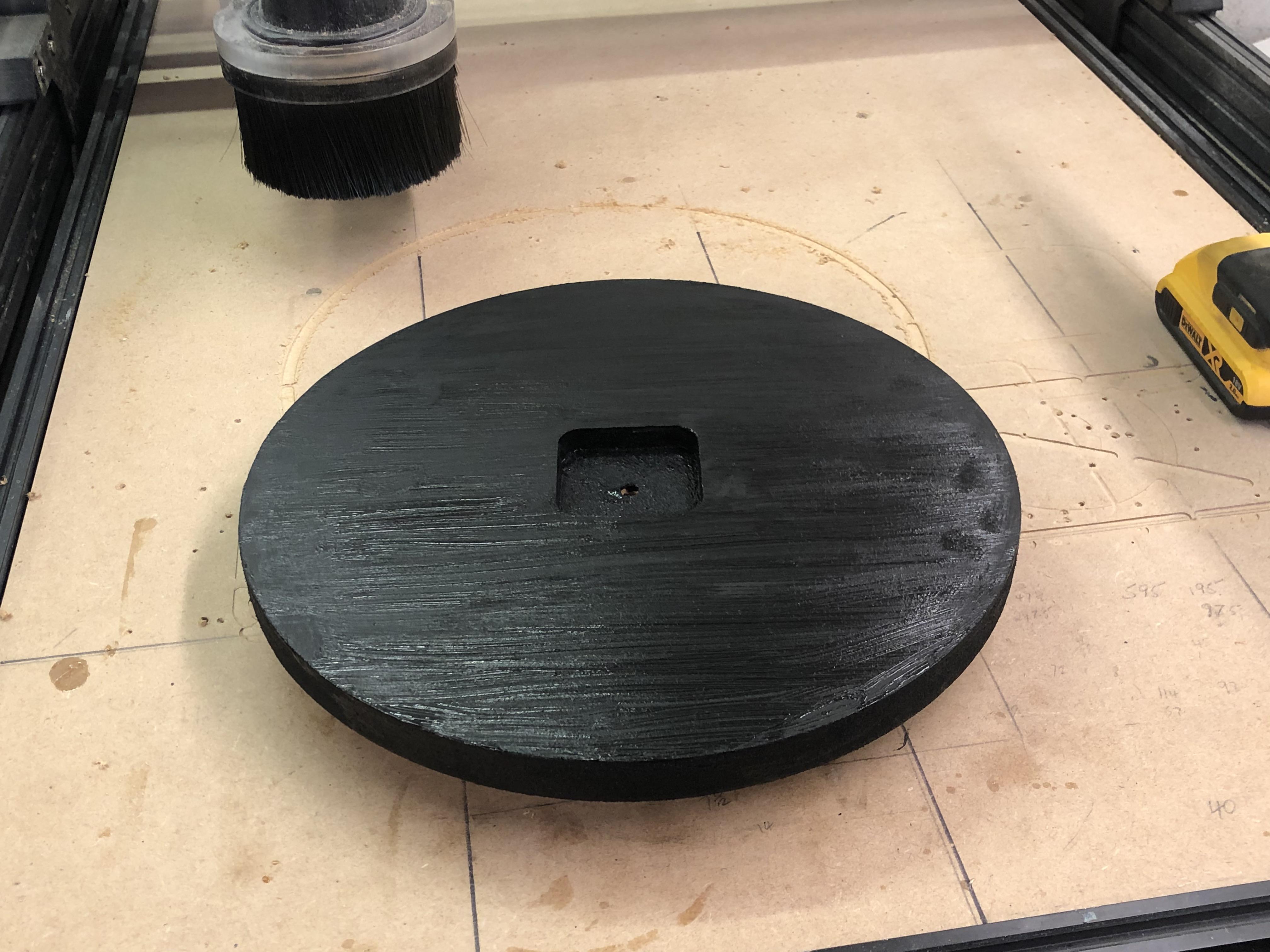
After we have sanded the clock base, we can now paint it.
What I use is blackboard paint, you can brush it on and it dries leaving a semi brushless finish, I do the back first let it dry. Its dry in a couple of hours too.
Paint the face side, , I like the finish to be Matt, let it dry and put to one side (you can now varnish the base if you prefer that finish)
We can now move onto the Face plate.
Acrylic Face Plate Design and Cut Out

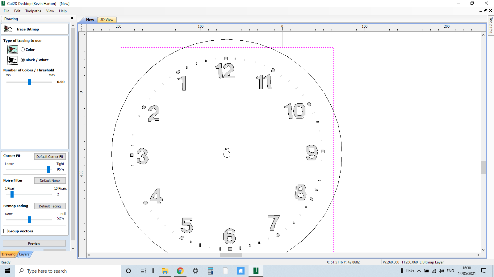
In this operation we import a reverse clock image.
The first process with the reverse clock is to find a template we can use, the idea is just to give us a template to work with so the clock numbers align with the pointers.
I looked online and found 2 or 3 which were suitable.
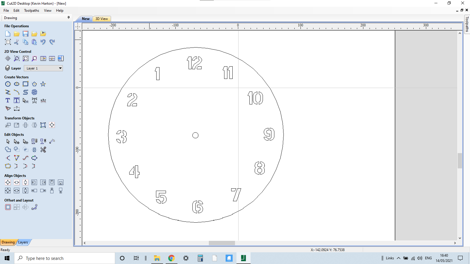
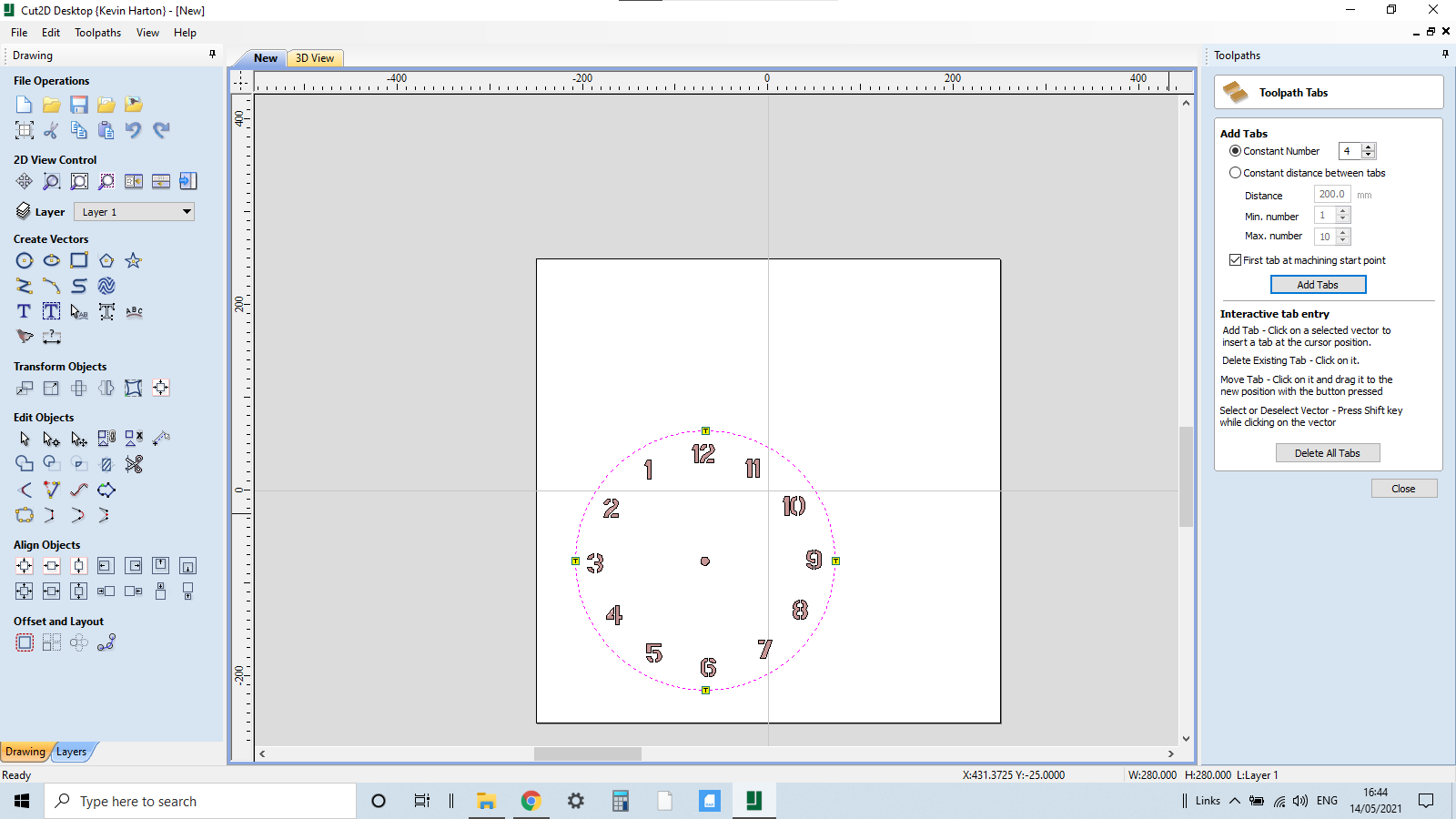
Import Bitmap, select file and import. Trace bitmap and size it to the perimeter of the inner circle and centralise. We can now go to text and start adding the clock numbers, I'm using a stencil font for the numbers this keeps the numbers whole on numbers 6,8,9,10
Delete the bitmap leaving just our clock numbers.
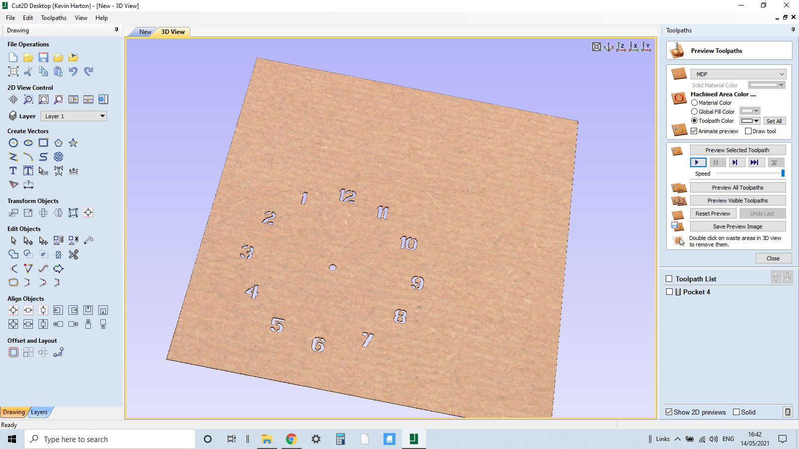
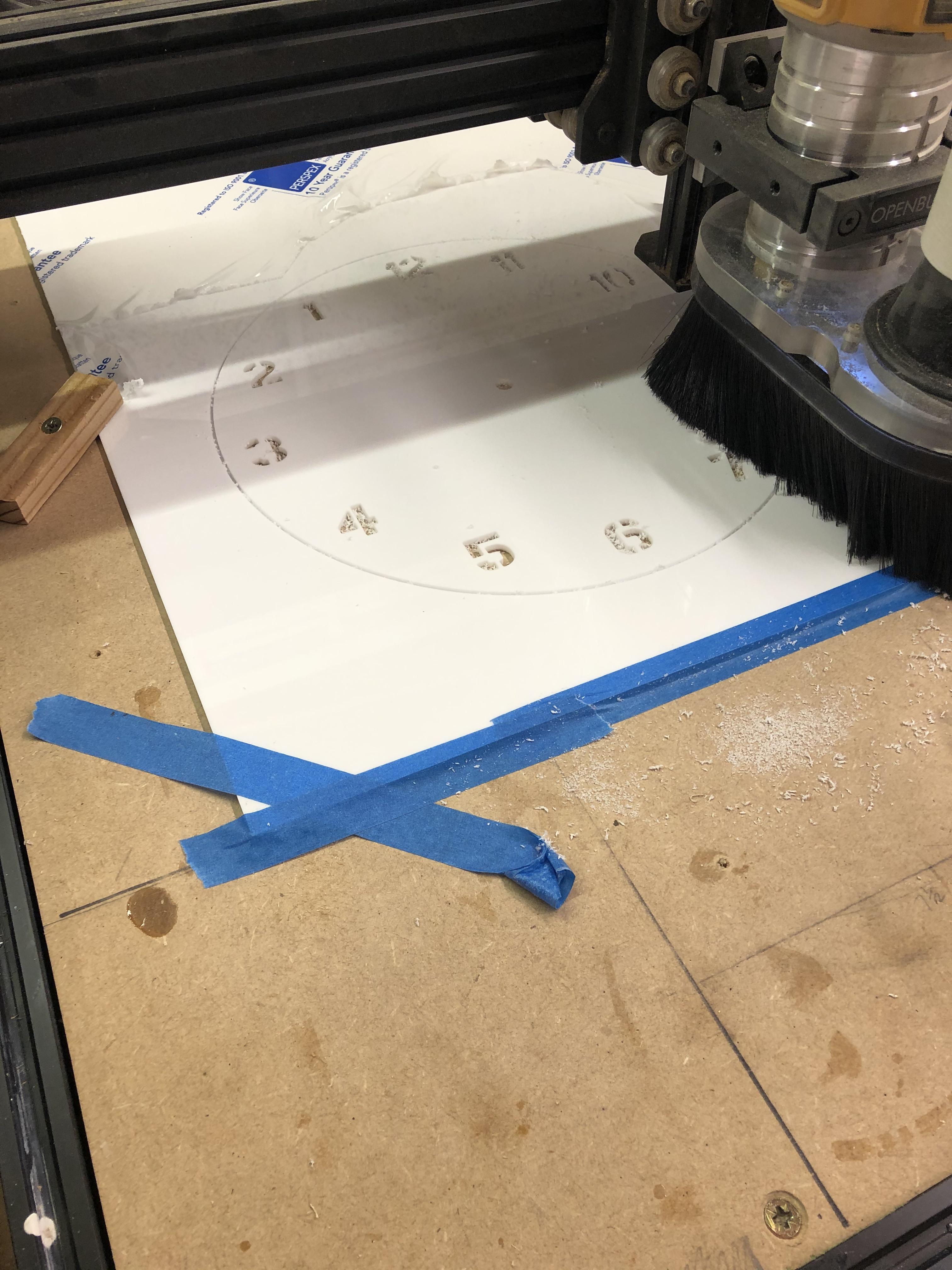
Cutting operation 4 will be cutting out the clock numbers.
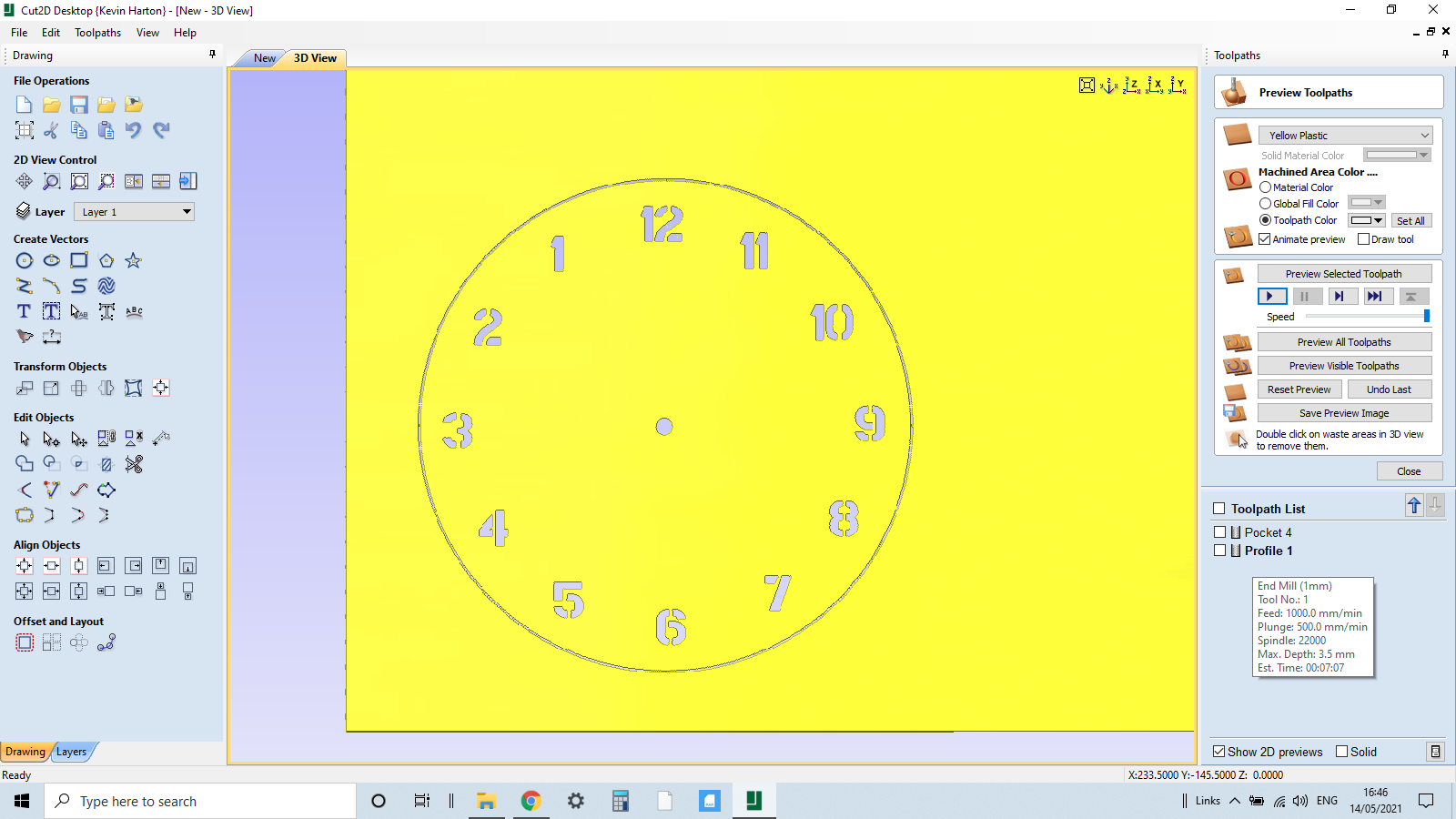
Set up : depth of material will be 3.2 for the Acrylic i am using and working from the centre of the circle as the starting point.
I will be using a 2mm bit for the acrylic, for both the numbers and cutting out the circle.
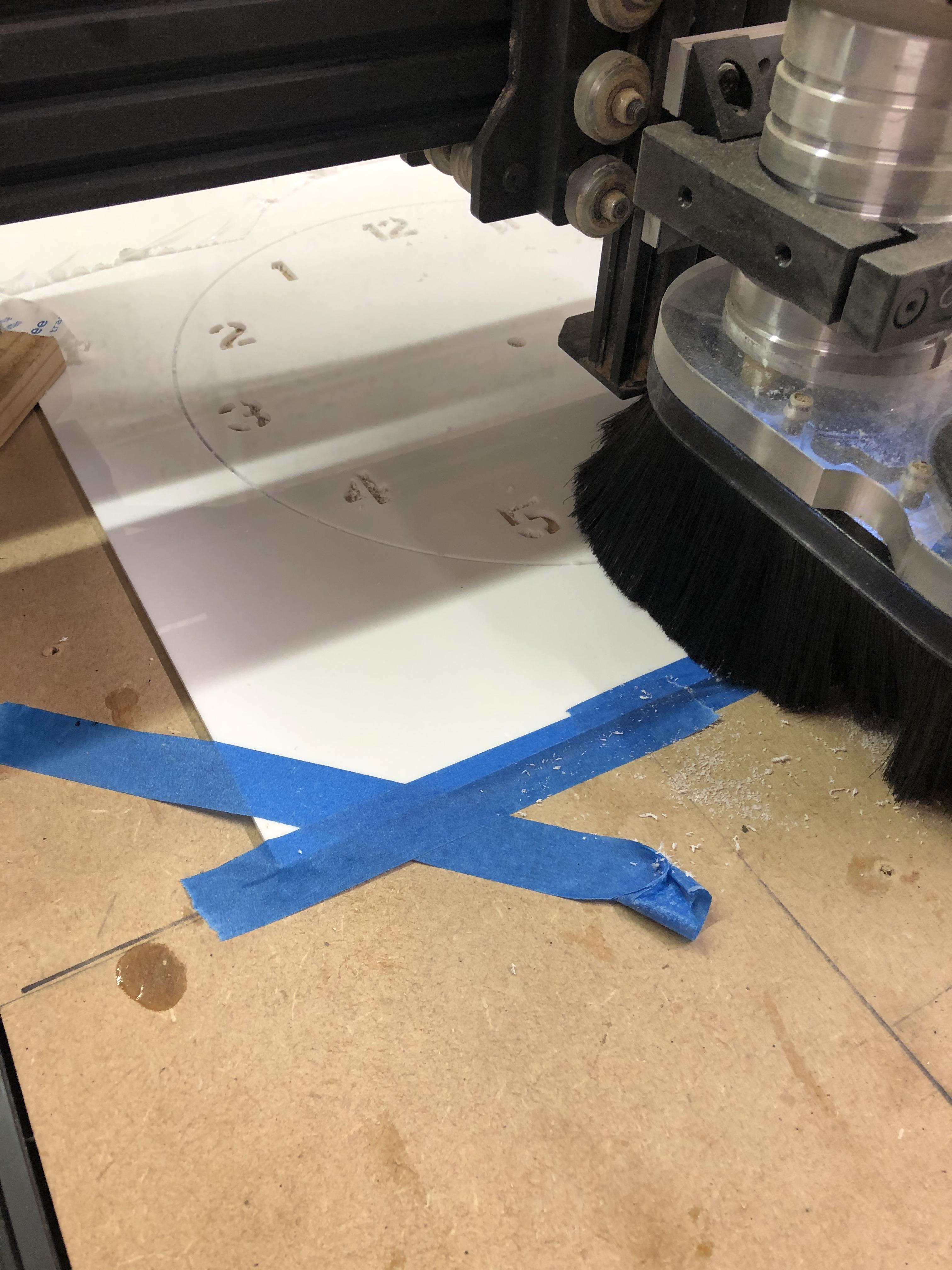
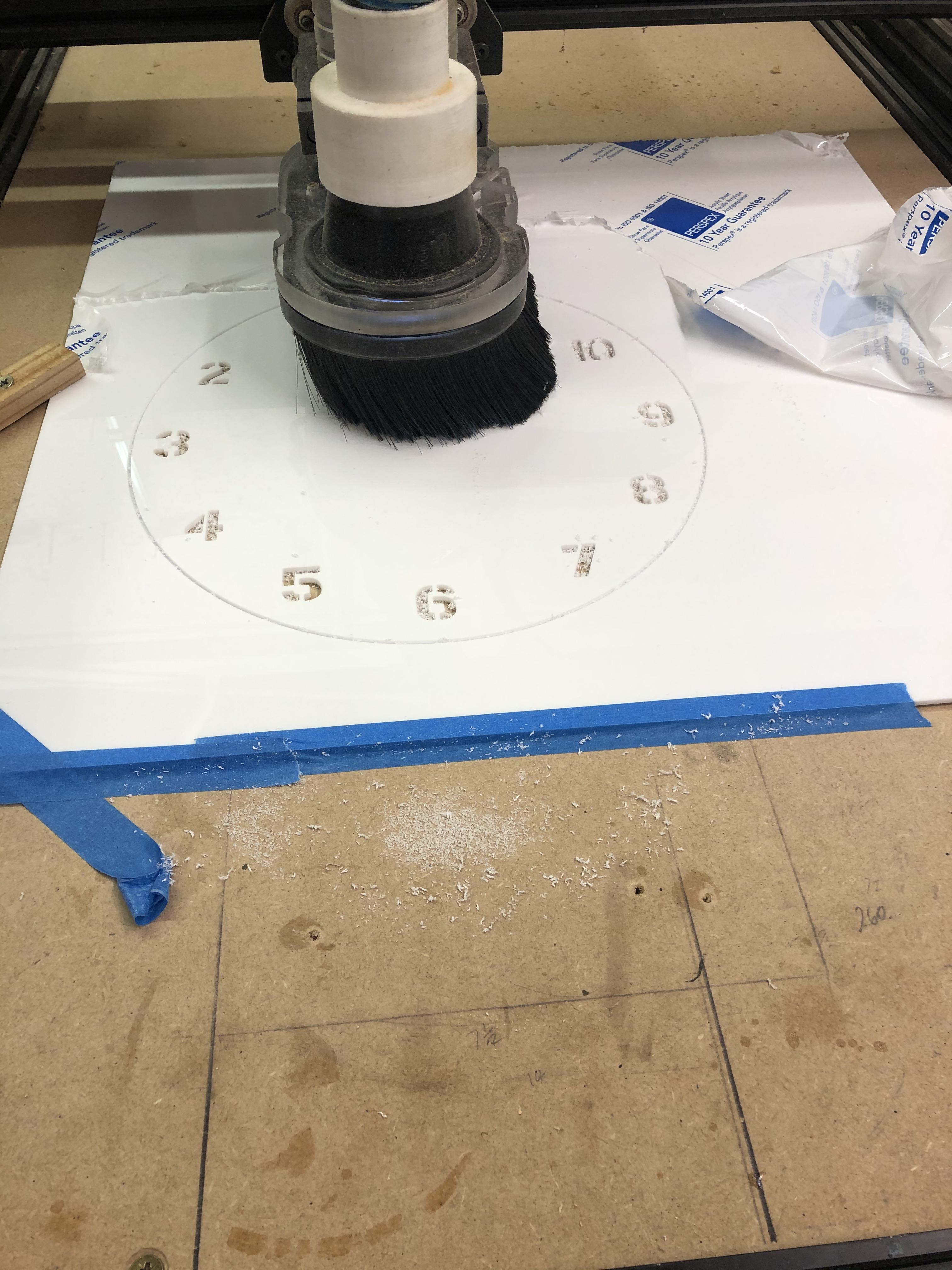
The numbers are a pocket cut and will be the first of our Acrylic cuts. Cutting out the perimeter of the circle will be a profile cut using tabs, in both cases depth of cut will be 3.5 mm as we need to cut right through the Acrylic.
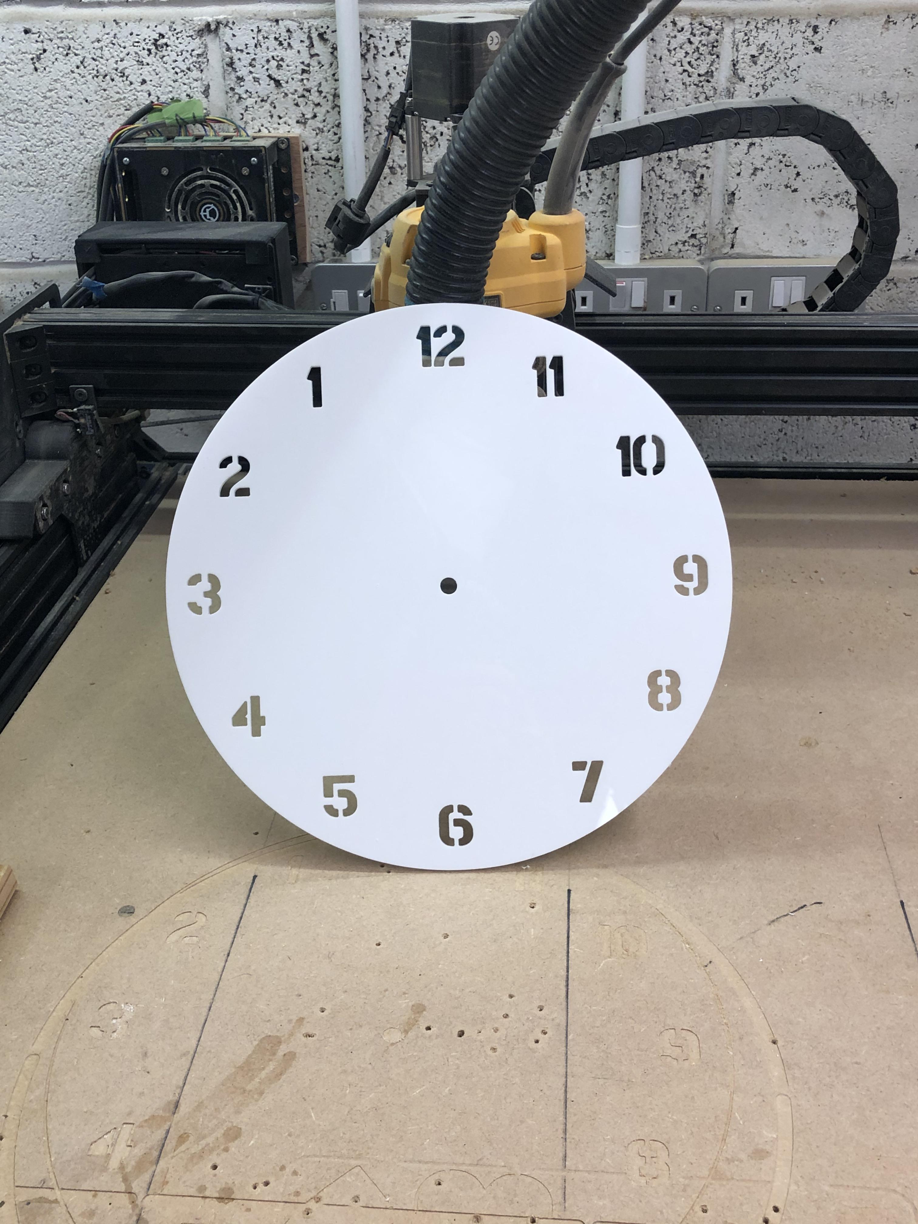
Once everything is cut we can remove from the spoil board, cut the tabs and lightly sand the edges.
Assembling the Reverse Clock
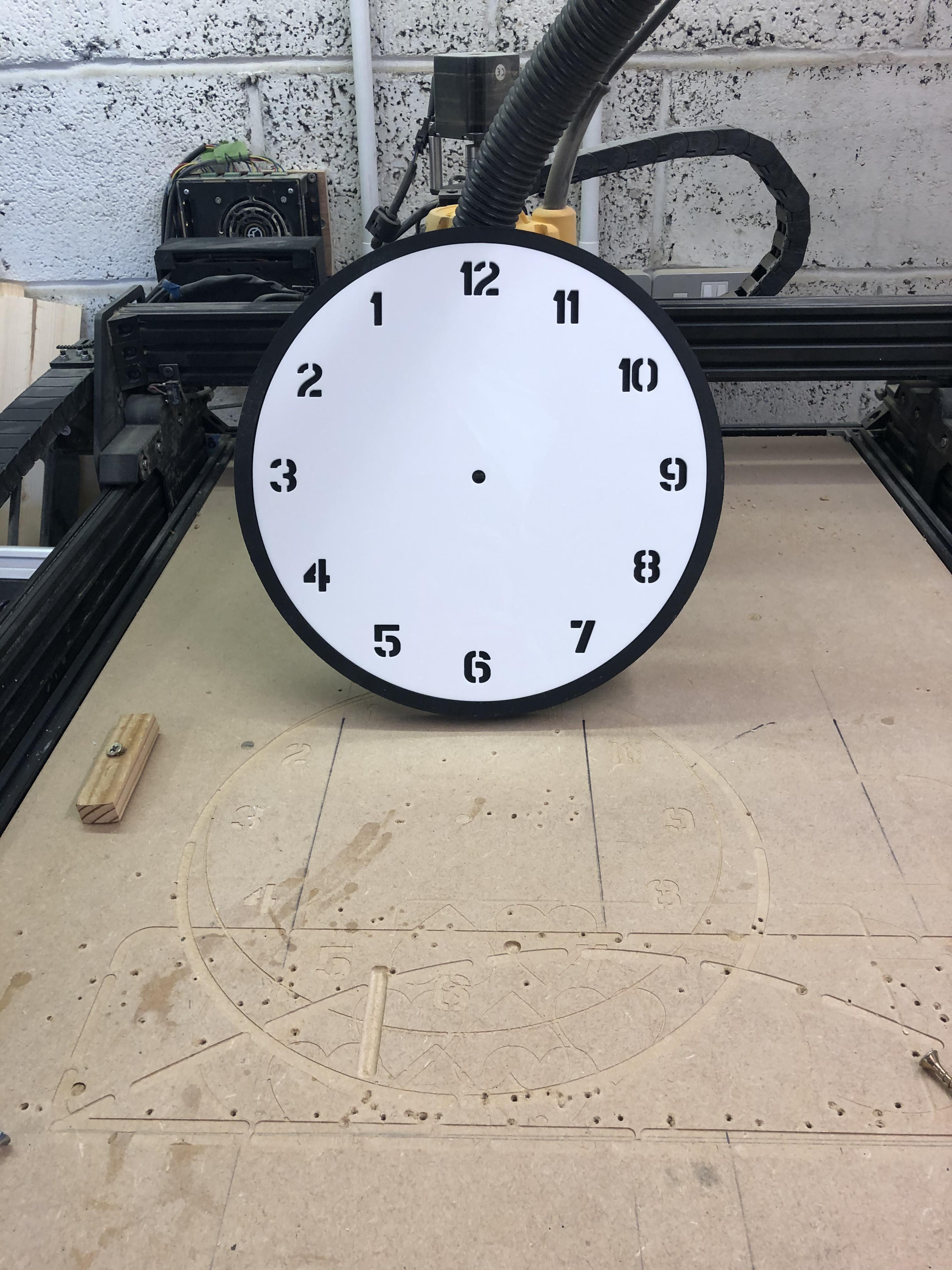
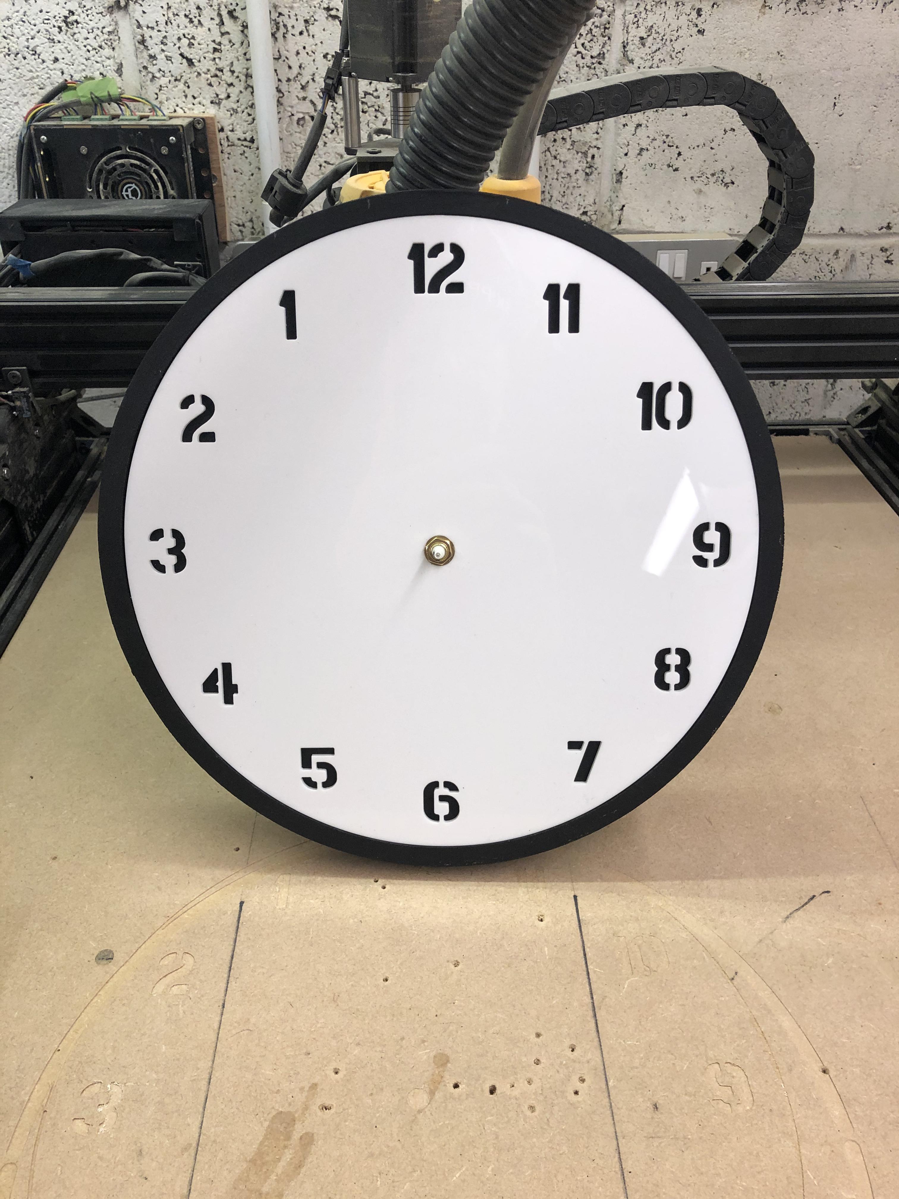
To assemble the clock, we need to align the clock face with the pocket we have cut out for the mechanism i:e 12 will need to centralised to one of the horizontal edges of the pocket, this will be the top edge of the mechanism. The battery slot will be at 6 o clock.
If the acrylic is a snug fit within the pocket happy days, no need to use any adhesive or double sided tape as the securing nut on the mechanism will hold it in place as well, otherwise I would use thin double sided tape.
At this stage we need to think about how we are going to suspend the clock, the choice is yours there are lots of options out there.
On the mechanism we fit the rubber washer before inserting into the pocket, secure the shaft with the the nut and washer.
Attach the pointers as it says in the instructions aligning to 12 o clock, insert an AA battery and set to the correct time with the dial on the mechanism, hey presto our clock is complete.
Enjoy the clock!
The End
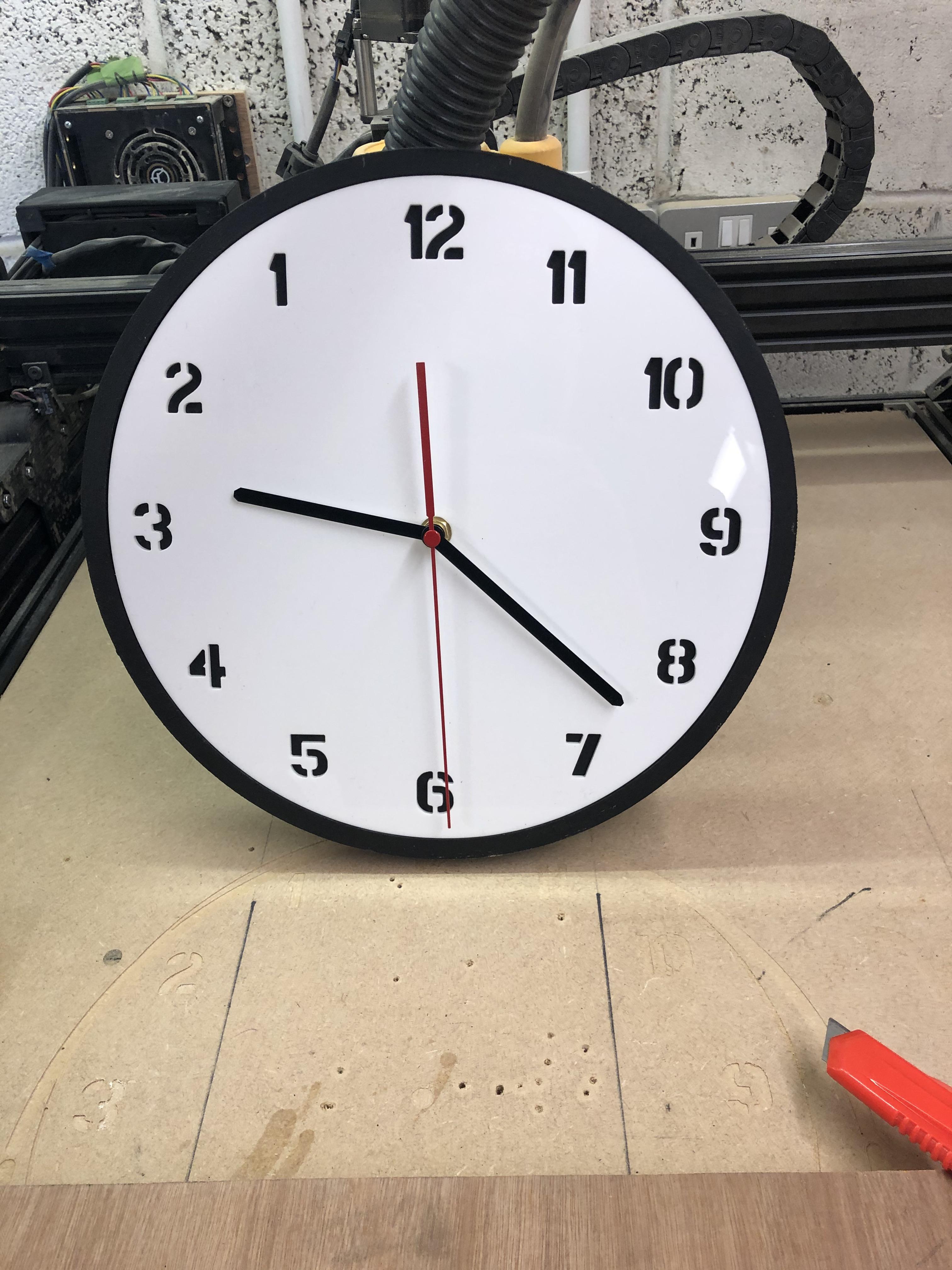
I hope you enjoyed this Instructable, and its given you some pointers in making a clock, a reverse clock is a bit different but the process would be the same for a normal clock as well and you could use different colour Acrylic and a different colour base, different coloured pointers and you could make it bigger or smaller.
The possibilities are endless.
Thanks for looking.